WO2013110554A1 - Aufnahmemagazin - Google Patents
Aufnahmemagazin Download PDFInfo
- Publication number
- WO2013110554A1 WO2013110554A1 PCT/EP2013/050933 EP2013050933W WO2013110554A1 WO 2013110554 A1 WO2013110554 A1 WO 2013110554A1 EP 2013050933 W EP2013050933 W EP 2013050933W WO 2013110554 A1 WO2013110554 A1 WO 2013110554A1
- Authority
- WO
- WIPO (PCT)
- Prior art keywords
- sample
- magazine
- magazine tray
- carriers
- displacement
- Prior art date
- Legal status (The legal status is an assumption and is not a legal conclusion. Google has not performed a legal analysis and makes no representation as to the accuracy of the status listed.)
- Ceased
Links
Images


Classifications
-
- G—PHYSICS
- G01—MEASURING; TESTING
- G01N—INVESTIGATING OR ANALYSING MATERIALS BY DETERMINING THEIR CHEMICAL OR PHYSICAL PROPERTIES
- G01N35/00—Automatic analysis not limited to methods or materials provided for in any single one of groups G01N1/00 - G01N33/00; Handling materials therefor
- G01N35/02—Automatic analysis not limited to methods or materials provided for in any single one of groups G01N1/00 - G01N33/00; Handling materials therefor using a plurality of sample containers moved by a conveyor system past one or more treatment or analysis stations
- G01N35/026—Automatic analysis not limited to methods or materials provided for in any single one of groups G01N1/00 - G01N33/00; Handling materials therefor using a plurality of sample containers moved by a conveyor system past one or more treatment or analysis stations having blocks or racks of reaction cells or cuvettes
-
- G—PHYSICS
- G01—MEASURING; TESTING
- G01N—INVESTIGATING OR ANALYSING MATERIALS BY DETERMINING THEIR CHEMICAL OR PHYSICAL PROPERTIES
- G01N1/00—Sampling; Preparing specimens for investigation
- G01N1/28—Preparing specimens for investigation including physical details of (bio-)chemical methods covered elsewhere, e.g. G01N33/50, C12Q
-
- G—PHYSICS
- G01—MEASURING; TESTING
- G01N—INVESTIGATING OR ANALYSING MATERIALS BY DETERMINING THEIR CHEMICAL OR PHYSICAL PROPERTIES
- G01N35/00—Automatic analysis not limited to methods or materials provided for in any single one of groups G01N1/00 - G01N33/00; Handling materials therefor
- G01N35/02—Automatic analysis not limited to methods or materials provided for in any single one of groups G01N1/00 - G01N33/00; Handling materials therefor using a plurality of sample containers moved by a conveyor system past one or more treatment or analysis stations
- G01N35/04—Details of the conveyor system
- G01N2035/0474—Details of actuating means for conveyors or pipettes
- G01N2035/0491—Position sensing, encoding; closed-loop control
- G01N2035/0493—Locating samples; identifying different tube sizes
-
- G—PHYSICS
- G01—MEASURING; TESTING
- G01N—INVESTIGATING OR ANALYSING MATERIALS BY DETERMINING THEIR CHEMICAL OR PHYSICAL PROPERTIES
- G01N35/00—Automatic analysis not limited to methods or materials provided for in any single one of groups G01N1/00 - G01N33/00; Handling materials therefor
- G01N35/02—Automatic analysis not limited to methods or materials provided for in any single one of groups G01N1/00 - G01N33/00; Handling materials therefor using a plurality of sample containers moved by a conveyor system past one or more treatment or analysis stations
- G01N35/04—Details of the conveyor system
- G01N2035/0496—Other details
- G01N2035/0498—Drawers used as storage or dispensing means for vessels or cuvettes
Definitions
- the invention relates to a receiving magazine for receiving a multiplicity of sample carriers elongated along a longitudinal axis, in particular substantially cylindrical sample carriers. It further relates to a method for monitoring the presence of sample carriers and / or sample holders on a magazine tray according to claim 8.
- sample sorter e.g. a sample sorter known and described in DE 199 12 211 A1
- sample sorter with the samples contained in tubular sample carriers, e.g. Samples of body fluids from patients can be sorted automatically.
- the sample sorter disclosed therein comprises an entrance area and an exit area, wherein in both areas tableau-like extension tables are present, which can be equipped with sample holders, there also called racks, which sample holders are designed to receive the sample carriers.
- the extension table can be pulled out into a loading position, in which a manual loading is possible. Subsequently, the extension table is moved to a standby position, in which the individual sample carriers can be detected and sorted with a robot gripper.
- Such automated sorting not only reduces labor costs in an appropriate laboratory, it also reduces the susceptibility to errors and can speed up operations.
- corresponding automations are not limited to sample sorters manifested in a single device, as disclosed in DE 199 12 211 A1, it is also conceivable to position similar receiving magazines in automated analysis systems, from where, for example, an automatic analysis section with individual samples or where, at the end of an automated analysis run, samples that have passed through them are collected and temporarily stored prior to manual collection.
- such receiving magazines as the known sample sorter according to DE 199 12 211 A1 has in its input area or its output area, manually loaded or emptied, including an operator in DE 199 12 211 A1 referred to as Auszugwaitchen sliding magazine shelves from the standby position spends into the loading position (either mechanically raises or motor driven), then set accordingly sample holder or remove or remove from the sample holders remaining on the magazine tray sample holder or set in this appropriate sample carrier.
- this manual assembly constitutes a source of error.
- an operator can miss the removal of one or more sample holders or sample carriers or sample carriers arranged thereon and the magazine tray can be moved back into the ready position prematurely in the event of a magazine tray to be emptied.
- false information is given, certain locations for sample carriers or sample holders are indicated as unoccupied, on which sample carriers or sample holders are located; vice versa.
- sample holders to be manipulated can not be taken by an automated system if the corresponding positions are designated as "unoccupied” or by acting as a supposedly unoccupied position in a storage area guided positions in which accidentally sample carrier have remained, another sample carrier is turned off, resulting in a collision, in the worst case to a destruction of the sample carrier and thus eg in the case of an automated medical diagnostic system, contamination of this system with, for example, a blood sample, a urine sample or the like, and thus a system standstill for a decontamination to be performed.
- a sample carrier should be placed in a sample holder supposedly present there without the sample holder actually being located there. In this case, the sample carrier would not be taken safely, it could also lead to an accident and at worst a contamination of the system.
- the essential approach of the invention is now to install at least one stationary on the receiving magazine (in particular with respect to the sliding magazine tray) arranged non-contact detector for detecting the presence of objects for monitoring the presence of sample holder (s) or sample carrier (s) , which covers with a sensor area the area that is swept over when moving the magazine tray of sample holder (s) or sample carrier (s).
- a displacement sensor is provided which detects a displacement or a current position of the magazine tray when moving the same between the loading position and the standby position.
- the data acquired by this sensor combination that is to say the detector and the displacement sensor, are correlated in an evaluation unit.
- the correlation of the data can be done either directly by merging the data acquired by the detector with the values simultaneously sensed by the displacement sensor into a value tuple, but this can also be done with the interposition of further parameters, e.g. a time value which is clocked predetermined by the evaluation unit or a control assigned to the respective data of the detector or displacement sensor, wherein over equal time values then in the evaluation unit, a correlation between the values or data outputs of the detector and the displacement sensor is produced.
- further parameters e.g. a time value which is clocked predetermined by the evaluation unit or a control assigned to the respective data of the detector or displacement sensor, wherein over equal time values then in the evaluation unit, a correlation between the values or data outputs of the detector and the displacement sensor is produced.
- the non-contact detector may in particular be a light barrier, with advantage a transmittive light barrier (although basically a reflective light barrier is also possible).
- a light barrier represents a particularly simple, inexpensive and space-saving to manufacture and integrable in the system of the recording magazine possibility of such a detector.
- the displacement sensor may be an incremental sensor which detects in particular optically or magnetically. This type of embodiment of the displacement sensor also represents a realization which can be implemented cost-effectively and can be easily integrated into the receiving magazine. However, other forms of displacement sensors may also be used, such as electrical sensors (for example potentiometers or absolute encoders). It is also generally possible to integrate the displacement sensor in a drive when the drawer-like magazine tray moves motor driven.
- sample holders can be identified on the basis of geometric dimensions if different sample holders which can be inserted on the magazine tray have different geometric dimensions in the direction of the displacement path of the magazine tray or in the vertical direction. It is also fundamentally possible to detect differently sized sample carriers and possibly to draw conclusions about certain samples, if these are typically located in sample carriers of specific dimensions.
- Typical sample carriers such as those used in particular in medical analysis and diagnostic laboratories, are cylindrical receiving rings, in particular made of plastic. These extend with their longitudinal axis in corresponding sample holders in the vertical direction, so that with a preferably provided as described in the described advantageous embodiment grid of a plurality of vertically stacked detectors, e.g. their length, as well as possibly at different widths whose width can be detected. It is also possible to arrange several rows of vertically stacked detectors next to each other to obtain an even denser sensor image.
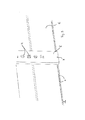
- Figure 1 is a perspective view of essential components of an embodiment of an inventive recording magazine.
- FIG. 2 shows a measurement profile obtained by evaluating the measurement results of the non-contact detector for detecting the presence of objects in its sensor area and the displacement sensor in the evaluation unit;
- Fig. 3 is an enlarged detail of the illustration of Fig. 1 in a designated there III area.
- Fig. 1 are as essential components of a receiving magazine according to the invention in a possible embodiment, a drawer-like substantially horizontally displaceable magazine tray 1 and a stationary arranged on a corresponding base of the receiving magazine pair of each other in substantially to the longitudinal extension and movement direction of the magazine tray 1 perpendicular Direction opposite, extending substantially vertically extending sensor strips 2 and 3.
- sensor strips 2, 3 are, as already stated, rigidly and fixedly connected to a base of the receiving magazine, which is not shown here in detail; relative to this base, the magazine tray 1 is drawer-like and substantially horizontally displaceable.
- the magazine tray 1 has a multiplicity of equidistantly arranged markings 6, which can consist, for example, of highly reflective elements, recesses or the like introduced thereinto into the material of the magazine tray.
- markings 6 can consist, for example, of highly reflective elements, recesses or the like introduced thereinto into the material of the magazine tray.
- an opening 7 can be seen in the sensor strip 2, in which a corresponding sensor is arranged, which has a detection section in the direction of the markings 6 and can detect them.
- a displacement sensor is realized, which detects at a relative displacement of the magazine tray 1 relative to the sensor bar 2, the passing deleting markings and thus detects a progressive displacement of the magazine tray 1.
- sample carriers 8, 9, 10 are shown in FIG. These are freely attachable to the magazine tray 1, provided with holding openings 11 receiving blocks for tube-shaped sample holder.
- the sample carriers 8, 9 and 10 are equipped in the illustration shown in different ways with sample holders.
- a plurality of sample holders 12 of a first type is arranged on the sample carrier 8, wherein in a left-hand row shown in the figure on the left only a single sample holder is arranged, two subsequent rows of holding openings free of sample carriers, that is bare, four subsequent rows are completely equipped with sample holders 12 and subsequently three further rows with holding openings are unpopulated.
- a sample holder 13 is arranged only in a rear position of the second row with holding openings 11.
- the sample holder 13 is shorter compared to the sample holders 12 of different dimensions, in particular in its longitudinal extension, thus projects less high out of the holding opening 11.
- the sample carrier 10 is completely empty.
- the sensor Ledge 2 arranged sensor with the attached on the magazine tray markers 6 determines a distance covered the magazine tray. Because of the arrangement of a plurality of sensor elements in the vertical direction arranged one above the other on the sensor strips 2, 3, different numbers of the sensors emit a signal at different heights of the detected objects. For flatter items, the higher sensors will not output a signal.
- the respectively detected signals of the sensors arranged in the openings 4, 5 and of the displacement sensor are correlated with each other supplied to an evaluation unit not shown here, combined there to a mounting profile, as shown for the situation shown in FIG. 1 in Fig. 2 , Schematically, the individual signals 14, which the sensor arranged in the opening 7 perceives upon detection of a marking 6 passing in each case in its detection field, are shown here in the lower section, wherein this representation here does not correspond to the actual scale but is only schematic. In fact, considerably more markers 6 are arranged than individual signals 14 are illustrated here.
- the detector evaluation or the profile in FIG. 2 is shown in the same orientation as given for the evaluated component pattern of the magazine tray 1 in FIG. 1. That the left-side beginning of the profile profile in FIG. 2 corresponds to the edge region of the magazine tray 1 shown on the left in FIG. 1 and the assembly with sample holders and sample carriers arranged thereon.
- the profile for the front edge of the magazine tray 1 is shown in FIG. 2 on the left-hand side and designated 15.
- the light barrier arrangement detects the front edge of the first sample holder 8 as a detector for the presence of objects, as shown in the profile section 16.
- the vertically higher-order light barrier sensors on the sensor strips 2 and 3 then also detect the presence of an object, this signal section 17 corresponds to the leftmost sample holder 12.
- the profile profile again detects the contour of the sample carrier 8 and moves in the region 18 up again, ie the arranged in vertical height light barrier elements in the sensor strips 2 and 3 detect there the four successive rows of sample carriers 12 on the sample holder 8 with a vertical profile drop in the respective spaces.
- the profile profile drops further vertically, i. further vertically higher arranged light barrier sensors, which have previously struck due to the sample carrier 8, give no signal, since there is space between the end faces of the sample carrier 8 and the sample carrier 9.
- the subsequent vertical rise of the profile indicates the presence of the sample holder 9, wherein in section 20, a further vertical increase indicates the presence of the sample carrier 13, wherein in Fig. 2 here a profile profile is shown for a slightly different arrangement of the sample carrier 13 relative to the FIG. 1, namely instead of a sample carrier 13 arranged in the second row with openings 11 in the first leftmost row of this sample holder 9.
- this profile profile or this detected profile image can be further evaluated and, for corresponding instructions for automatic loading and unloading of the sample holder, e.g. in an input or output area of an automated sample handling device, which may in particular comprise a robot for detecting and displacing individual sample carriers.
- an automated sample handling device which may in particular comprise a robot for detecting and displacing individual sample carriers.
- the controller first recognizes that on the magazine tray 1 a total of three sample holders are arranged with sample carriers on the first sample holder 8 and the second sample holder 9 and a sample holder 10 not equipped with samples.
- the system can in any case be transversely determine the position of loaded and unequipped rows with holding openings to the direction of displacement of the magazine tray 1 and differ due to the different profile heights different types of sample holders 12 and 13, which in the profile height shown in Fig. 2 profile profile 17 and in the area 18 on the one hand and in On the other hand.
- This information can now be used to release correspondingly unpopulated rows of holding openings on sample carriers, to output a disturbance, for example, if no sample holder is arranged in a section intended for loading, and the like.
- the sensor device in the sensor strips 2 and 3 not only takes a profile as shown in FIG. 2, but at the same time determines by a distance measurement to the respective detected sample carriers, in which position seen in the transverse direction to the direction of displacement of the magazine tray 1, a sample carrier 12, 13 is arranged, which in the embodiment shown in particular from both lateral edges is possible, if the light barrier elements are each mutually arranged in the openings 4 and 5, ie in each case a transmitter or transceiver below and vertically above the same a receiver or reflector and vice versa.
- the light barrier elements are each mutually arranged in the openings 4 and 5, ie in each case a transmitter or transceiver below and vertically above the same a receiver or reflector and vice versa.
Landscapes
- Chemical & Material Sciences (AREA)
- Physics & Mathematics (AREA)
- Health & Medical Sciences (AREA)
- Life Sciences & Earth Sciences (AREA)
- Analytical Chemistry (AREA)
- Biochemistry (AREA)
- General Health & Medical Sciences (AREA)
- General Physics & Mathematics (AREA)
- Immunology (AREA)
- Pathology (AREA)
- Chemical Kinetics & Catalysis (AREA)
- Automatic Analysis And Handling Materials Therefor (AREA)
Priority Applications (2)
| Application Number | Priority Date | Filing Date | Title |
|---|---|---|---|
| JP2014553673A JP6129875B2 (ja) | 2012-01-27 | 2013-01-18 | 収容マガジンおよび監視方法 |
| US14/374,587 US9541566B2 (en) | 2012-01-27 | 2013-01-18 | Accommodating magazine |
Applications Claiming Priority (2)
| Application Number | Priority Date | Filing Date | Title |
|---|---|---|---|
| EP12152830.1A EP2620775B1 (de) | 2012-01-27 | 2012-01-27 | Aufnahmemagazin |
| EP12152830.1 | 2012-01-27 |
Publications (1)
| Publication Number | Publication Date |
|---|---|
| WO2013110554A1 true WO2013110554A1 (de) | 2013-08-01 |
Family
ID=47563521
Family Applications (1)
| Application Number | Title | Priority Date | Filing Date |
|---|---|---|---|
| PCT/EP2013/050933 Ceased WO2013110554A1 (de) | 2012-01-27 | 2013-01-18 | Aufnahmemagazin |
Country Status (5)
| Country | Link |
|---|---|
| US (1) | US9541566B2 (enExample) |
| EP (1) | EP2620775B1 (enExample) |
| JP (1) | JP6129875B2 (enExample) |
| ES (1) | ES2545626T3 (enExample) |
| WO (1) | WO2013110554A1 (enExample) |
Families Citing this family (7)
| Publication number | Priority date | Publication date | Assignee | Title |
|---|---|---|---|---|
| DE102016112114A1 (de) | 2016-07-01 | 2018-01-04 | Hamilton Storage Gmbh | Verfahren zum Beschicken einer Probenspeichereinrichtung für eine Mehrzahl von mit Probengefäßen bestückten Probenträgern, und Probenbeschickungssystem |
| US10613020B2 (en) * | 2017-08-10 | 2020-04-07 | The Boeing Company | Burr detection systems and methods |
| CN114441260B (zh) | 2017-11-27 | 2025-01-28 | 徕卡生物系统成像股份有限公司 | 载片架确定系统 |
| EP3520897B1 (en) * | 2018-02-01 | 2023-10-04 | Beckman Coulter, Inc. | Configurable placement indication for sample tube rack receptacles |
| EP3789772B1 (en) * | 2019-09-05 | 2025-03-26 | Roche Diagnostics GmbH | Method for determining a position of a rack on a rack placement unit of a laboratory handling system and laboratory handling system |
| EP4306965A4 (en) * | 2021-03-08 | 2025-01-15 | Hitachi High-Tech Corporation | AUTOMATIC ANALYSIS DEVICE |
| EP4329937A4 (en) * | 2021-04-27 | 2025-02-26 | Quest Diagnostics Investments LLC | WARNING SYSTEM FOR DECAPSULING/CAPSULING SYSTEM |
Citations (4)
| Publication number | Priority date | Publication date | Assignee | Title |
|---|---|---|---|---|
| US5923428A (en) * | 1995-07-26 | 1999-07-13 | Psc Inc. | Method and apparatus for measuring dimensions of objects on a conveyor |
| US6255614B1 (en) * | 1999-05-14 | 2001-07-03 | Sysmex Corporation | Specimen-container transfer apparatus |
| DE19912211A1 (de) * | 1999-03-18 | 2001-12-13 | Robert Hecht | Probensortierer |
| US20110115610A1 (en) * | 2008-07-09 | 2011-05-19 | Thomas Fergus Hughes | Laboratory sample archiving apparatus and method |
Family Cites Families (22)
| Publication number | Priority date | Publication date | Assignee | Title |
|---|---|---|---|---|
| US3955179A (en) * | 1971-12-14 | 1976-05-04 | Tore Planke | Apparatus for automatic pattern recognition and registration of empty bottles |
| US4553217A (en) * | 1981-07-08 | 1985-11-12 | Ball Corporation | Glassware gauging system |
| JP2657296B2 (ja) * | 1987-10-09 | 1997-09-24 | セイコー電子工業株式会社 | 微量液体反応装置 |
| US5038023A (en) * | 1989-06-28 | 1991-08-06 | C. Itoh Information Systems Development, Inc. | System for storing and monitoring bar coded articles such as keys in a drawer |
| DE4023149A1 (de) * | 1990-07-20 | 1992-01-23 | Kodak Ag | Vorrichtung zum abtasten von behaeltern mit einer fluessigkeit |
| US5266810A (en) * | 1992-04-14 | 1993-11-30 | Imtec, Inc. | Package height detector having a first group of light sensors selectively enabled by the detector outputs of a second group of light sensors |
| JPH06208637A (ja) * | 1993-01-11 | 1994-07-26 | Sumitomo Electric Ind Ltd | 光学式走査装置 |
| JPH07287018A (ja) * | 1994-04-19 | 1995-10-31 | Hitachi Ltd | 試料管ラック識別装置 |
| DE10033077A1 (de) * | 2000-07-07 | 2002-01-17 | Sick Ag | Lichtgitter |
| CN1754081A (zh) * | 2003-02-24 | 2006-03-29 | 塞德斯股份公司 | 用于无接触式测量物体的方法 |
| JP2007147558A (ja) * | 2005-11-30 | 2007-06-14 | Juki Corp | 分注装置 |
| JP4804949B2 (ja) * | 2006-02-15 | 2011-11-02 | グローリー株式会社 | 棒金収納庫 |
| JP2008084087A (ja) * | 2006-09-28 | 2008-04-10 | Glory Ltd | 棒金収納庫 |
| US7684034B2 (en) * | 2007-05-24 | 2010-03-23 | Applied Vision Company, Llc | Apparatus and methods for container inspection |
| US8842183B2 (en) * | 2008-08-08 | 2014-09-23 | Snap-On Incorporated | Image-based inventory control system with automatic calibration and image correction |
| US9671357B2 (en) * | 2009-12-10 | 2017-06-06 | Emhardt Glass S.A. | System and method for monitoring hot glass containers to enhance their quality and control the forming process |
| US20130076898A1 (en) * | 2011-08-01 | 2013-03-28 | Richard Philippe | Apparatus, systems, and methods for tracking medical products using an imaging unit |
| US8700210B2 (en) * | 2011-09-29 | 2014-04-15 | Aesynt Incorporated | Systems, methods and computer program products for visually emphasizing portions of a medication storage device |
| DE102011083757A1 (de) * | 2011-09-29 | 2013-04-04 | Krones Aktiengesellschaft | Triggerlichtgitter und Verfahren zur Positionsbestimmung von Behältern |
| US9004084B2 (en) * | 2011-10-13 | 2015-04-14 | Northwestern Systems Corp. | Method and apparatus for removing waste from a soiled container |
| DE102012102221A1 (de) * | 2012-03-16 | 2013-09-19 | Krones Ag | Vorrichtung zur verwendung bei einer inspektion eines behälters, inspektionssystem und inspektionsverfahren |
| US8972051B2 (en) * | 2012-05-29 | 2015-03-03 | Carefusion 303, Inc. | Multi-compartment step-drawer |
-
2012
- 2012-01-27 ES ES12152830.1T patent/ES2545626T3/es active Active
- 2012-01-27 EP EP12152830.1A patent/EP2620775B1/de active Active
-
2013
- 2013-01-18 US US14/374,587 patent/US9541566B2/en active Active
- 2013-01-18 WO PCT/EP2013/050933 patent/WO2013110554A1/de not_active Ceased
- 2013-01-18 JP JP2014553673A patent/JP6129875B2/ja active Active
Patent Citations (4)
| Publication number | Priority date | Publication date | Assignee | Title |
|---|---|---|---|---|
| US5923428A (en) * | 1995-07-26 | 1999-07-13 | Psc Inc. | Method and apparatus for measuring dimensions of objects on a conveyor |
| DE19912211A1 (de) * | 1999-03-18 | 2001-12-13 | Robert Hecht | Probensortierer |
| US6255614B1 (en) * | 1999-05-14 | 2001-07-03 | Sysmex Corporation | Specimen-container transfer apparatus |
| US20110115610A1 (en) * | 2008-07-09 | 2011-05-19 | Thomas Fergus Hughes | Laboratory sample archiving apparatus and method |
Also Published As
| Publication number | Publication date |
|---|---|
| JP6129875B2 (ja) | 2017-05-17 |
| EP2620775B1 (de) | 2015-05-27 |
| US9541566B2 (en) | 2017-01-10 |
| EP2620775A1 (de) | 2013-07-31 |
| ES2545626T3 (es) | 2015-09-14 |
| JP2015505056A (ja) | 2015-02-16 |
| US20150075298A1 (en) | 2015-03-19 |
Similar Documents
| Publication | Publication Date | Title |
|---|---|---|
| EP2620775B1 (de) | Aufnahmemagazin | |
| DE3046611C2 (enExample) | ||
| DE102004002831B4 (de) | Kommissionierplatz und Verfahren zum Kommissionieren mit einem Lichtgitter | |
| EP1494048B1 (de) | Lichtgitter | |
| DE2349901B2 (enExample) | ||
| WO2015019285A1 (de) | Biegepresse | |
| EP0863482A2 (de) | Anlage zur Bearbeitung von Chip- und/oder Magnetstreifenkarten | |
| EP3325211B1 (de) | Werkstückträger mit einem codeelement für eine fertigungsanlage | |
| DE3305277A1 (de) | Verfahren und vorrichtung zum selbsttaetigen ein- und auslagern von stueckgut | |
| DE69408023T2 (de) | Verfahren und Anordnung zum Eichen der Dickenmessanordnung des Querprofils eines flächigen Gutes | |
| DE102010053657A1 (de) | Verschiebe- und Positioniervorrichtung | |
| DE19752510B4 (de) | Einrichtung und Verfahren zur Erkennung und Unterscheidung geometrisch verschiedener Arten von fächerbildenden Auflagen in Kassetten und darauf abgelegten scheibenförmigen Objekten | |
| EP2474956B1 (de) | Transporteinheit und Verfahren zum Betrieb derselben | |
| EP2607867A1 (de) | Lagereinrichtung und Verfahren zur Bestandsüberwachung für eine Lagereinrichtung | |
| DE4421778C2 (de) | Vorrichtung zum selbsttätigen Zu- oder Abführen voller Spulen oder leerer Hülsen für eine Textilmaschine | |
| EP2296016A2 (de) | Verfahren zur Erfassung einer Kontamination an einem bewegten Objekt sowie Messvorrichtung hierzu | |
| DE102008037552A1 (de) | Verfahren und Vorrichtung zur Positionsbestimmung von Werkstücken | |
| DD285846A5 (de) | Roentgeneinrichtung | |
| DE202015100795U1 (de) | Detektionsvorrichtung einer Spritzenpumpe und Spritzenpumpe | |
| EP1895758B1 (de) | Verfahren und Vorrichtung zum Bearbeiten von Informationsträgern, insbesondere zum Auslesen von Speicherleuchtstoffplatten | |
| DE102010056593A1 (de) | Verfahren zur Ermittlung einer Ortsposition einer Seitenkante eines Materialstapels | |
| EP0833166A2 (de) | Einrichtung zum Überprüfen der Funktion einzelner Magnete einer Elektromagnetanordnung | |
| EP0143990A1 (de) | Vorrichtung zum Prüfen und Sortieren von elektronischen Bauteilen, insbesondere von integrierten Chips | |
| DE102018210342B4 (de) | System und Verfahren zum Erkennen einer für einen Andockvorgang eines Fahrzeugs an eine Wechselbrücke geeigneten Messstelle an der Wechselbrücke | |
| WO2024216321A1 (de) | Lagersystem zum lagern und verfahren zur positionskorrektur von stückgut |
Legal Events
| Date | Code | Title | Description |
|---|---|---|---|
| 121 | Ep: the epo has been informed by wipo that ep was designated in this application |
Ref document number: 13700580 Country of ref document: EP Kind code of ref document: A1 |
|
| ENP | Entry into the national phase |
Ref document number: 2014553673 Country of ref document: JP Kind code of ref document: A |
|
| WWE | Wipo information: entry into national phase |
Ref document number: 14374587 Country of ref document: US |
|
| NENP | Non-entry into the national phase |
Ref country code: DE |
|
| 122 | Ep: pct application non-entry in european phase |
Ref document number: 13700580 Country of ref document: EP Kind code of ref document: A1 |