WO2013108309A1 - 二次電池 - Google Patents
二次電池 Download PDFInfo
- Publication number
- WO2013108309A1 WO2013108309A1 PCT/JP2012/006031 JP2012006031W WO2013108309A1 WO 2013108309 A1 WO2013108309 A1 WO 2013108309A1 JP 2012006031 W JP2012006031 W JP 2012006031W WO 2013108309 A1 WO2013108309 A1 WO 2013108309A1
- Authority
- WO
- WIPO (PCT)
- Prior art keywords
- negative electrode
- secondary battery
- electrolyte
- battery according
- positive electrode
- Prior art date
- Legal status (The legal status is an assumption and is not a legal conclusion. Google has not performed a legal analysis and makes no representation as to the accuracy of the status listed.)
- Ceased
Links
Images




Classifications
-
- H—ELECTRICITY
- H01—ELECTRIC ELEMENTS
- H01M—PROCESSES OR MEANS, e.g. BATTERIES, FOR THE DIRECT CONVERSION OF CHEMICAL ENERGY INTO ELECTRICAL ENERGY
- H01M4/00—Electrodes
- H01M4/02—Electrodes composed of, or comprising, active material
- H01M4/36—Selection of substances as active materials, active masses, active liquids
- H01M4/38—Selection of substances as active materials, active masses, active liquids of elements or alloys
-
- H—ELECTRICITY
- H01—ELECTRIC ELEMENTS
- H01M—PROCESSES OR MEANS, e.g. BATTERIES, FOR THE DIRECT CONVERSION OF CHEMICAL ENERGY INTO ELECTRICAL ENERGY
- H01M4/00—Electrodes
- H01M4/02—Electrodes composed of, or comprising, active material
-
- H—ELECTRICITY
- H01—ELECTRIC ELEMENTS
- H01M—PROCESSES OR MEANS, e.g. BATTERIES, FOR THE DIRECT CONVERSION OF CHEMICAL ENERGY INTO ELECTRICAL ENERGY
- H01M10/00—Secondary cells; Manufacture thereof
- H01M10/36—Accumulators not provided for in groups H01M10/05-H01M10/34
-
- H—ELECTRICITY
- H01—ELECTRIC ELEMENTS
- H01M—PROCESSES OR MEANS, e.g. BATTERIES, FOR THE DIRECT CONVERSION OF CHEMICAL ENERGY INTO ELECTRICAL ENERGY
- H01M10/00—Secondary cells; Manufacture thereof
- H01M10/36—Accumulators not provided for in groups H01M10/05-H01M10/34
- H01M10/38—Construction or manufacture
-
- H—ELECTRICITY
- H01—ELECTRIC ELEMENTS
- H01M—PROCESSES OR MEANS, e.g. BATTERIES, FOR THE DIRECT CONVERSION OF CHEMICAL ENERGY INTO ELECTRICAL ENERGY
- H01M4/00—Electrodes
- H01M4/02—Electrodes composed of, or comprising, active material
- H01M4/36—Selection of substances as active materials, active masses, active liquids
- H01M4/38—Selection of substances as active materials, active masses, active liquids of elements or alloys
- H01M4/46—Alloys based on magnesium or aluminium
- H01M4/463—Aluminium based
-
- H—ELECTRICITY
- H01—ELECTRIC ELEMENTS
- H01M—PROCESSES OR MEANS, e.g. BATTERIES, FOR THE DIRECT CONVERSION OF CHEMICAL ENERGY INTO ELECTRICAL ENERGY
- H01M4/00—Electrodes
- H01M4/02—Electrodes composed of, or comprising, active material
- H01M4/36—Selection of substances as active materials, active masses, active liquids
- H01M4/38—Selection of substances as active materials, active masses, active liquids of elements or alloys
- H01M4/46—Alloys based on magnesium or aluminium
- H01M4/466—Magnesium based
-
- Y—GENERAL TAGGING OF NEW TECHNOLOGICAL DEVELOPMENTS; GENERAL TAGGING OF CROSS-SECTIONAL TECHNOLOGIES SPANNING OVER SEVERAL SECTIONS OF THE IPC; TECHNICAL SUBJECTS COVERED BY FORMER USPC CROSS-REFERENCE ART COLLECTIONS [XRACs] AND DIGESTS
- Y02—TECHNOLOGIES OR APPLICATIONS FOR MITIGATION OR ADAPTATION AGAINST CLIMATE CHANGE
- Y02E—REDUCTION OF GREENHOUSE GAS [GHG] EMISSIONS, RELATED TO ENERGY GENERATION, TRANSMISSION OR DISTRIBUTION
- Y02E60/00—Enabling technologies; Technologies with a potential or indirect contribution to GHG emissions mitigation
- Y02E60/10—Energy storage using batteries
-
- Y—GENERAL TAGGING OF NEW TECHNOLOGICAL DEVELOPMENTS; GENERAL TAGGING OF CROSS-SECTIONAL TECHNOLOGIES SPANNING OVER SEVERAL SECTIONS OF THE IPC; TECHNICAL SUBJECTS COVERED BY FORMER USPC CROSS-REFERENCE ART COLLECTIONS [XRACs] AND DIGESTS
- Y02—TECHNOLOGIES OR APPLICATIONS FOR MITIGATION OR ADAPTATION AGAINST CLIMATE CHANGE
- Y02P—CLIMATE CHANGE MITIGATION TECHNOLOGIES IN THE PRODUCTION OR PROCESSING OF GOODS
- Y02P70/00—Climate change mitigation technologies in the production process for final industrial or consumer products
- Y02P70/50—Manufacturing or production processes characterised by the final manufactured product
Definitions
- the present invention relates to a secondary battery.
- lithium ion secondary batteries have been used in a wide range of fields such as mobile phones and notebook computers because of their large battery capacity.
- the use of lithium ion secondary batteries as a drive source for vehicles has also been studied.
- the positive electrode of a lithium ion secondary battery is made of a ceramic such as a lithium composite oxide, and lithium ions enter and exit between the ceramic layers during charge and discharge.
- the negative electrode is made of carbon, and lithium ions enter and exit between carbon layers during charge and discharge. In this way, electric energy is created by repeatedly inserting and extracting lithium ions between the positive electrode and the negative electrode.
- Patent Document 1 lithium batteries using lithium metal for the negative electrode and metallic copper for the positive electrode have been developed.
- copper is dissolved at the positive electrode during charging, while lithium metal is plated on the negative electrode surface, and lithium is dissolved at the negative electrode during discharging, while metallic copper is plated on the positive electrode surface.
- the battery reaction due to the deposition / dissolution of the plating is simpler than that of a general lithium ion secondary battery. Therefore, an improvement in battery output can be expected.
- the electrode is a metal, the conductivity of the electrode itself is good. For this reason, it is not necessary to use a collector, and it can be used for an electrode as it is.
- the metal material used for the negative electrode is limited to lithium metal.
- the oxidation-reduction potential of hydrogen is 0 (zero)
- the oxidation-reduction potential of lithium metal is ⁇ 3 V, which is lower than other metals. For this reason, it is possible to increase the electromotive force of the battery by using lithium metal for the negative electrode.
- the battery capacity per unit mass of lithium metal is 3860 mAh / g, which is relatively large.
- the volume density of lithium metal is 0.5 g / cm 3, which is considerably low. For this reason, volume energy density will become low.
- the present invention has been made in view of such circumstances, and an object thereof is to provide a secondary battery having a high volumetric energy density.
- the secondary battery of the present invention is a secondary battery in which a negative electrode, an electrolyte for a negative electrode, a diaphragm, an electrolyte for a positive electrode, and a positive electrode are provided in that order. It is made of a negative electrode material having an element having an oxidation-reduction potential of 1.5 V or more and having a volume density higher than that of lithium metal, and the diaphragm is made of a solid electrolyte that allows only ions of the element to pass through.
- the negative electrode material has an element that is 1.5 V or higher with respect to the redox potential of hydrogen. For this reason, the secondary battery of high volume energy density can be provided.
- FIG. 6 is a cross-sectional explanatory view of a secondary battery of Example 2.
- FIG. 6 is an explanatory cross-sectional view of a secondary battery of Example 3.
- FIG. 6 is a cross-sectional explanatory view of a secondary battery of Example 4.
- the secondary battery is provided with a negative electrode, a negative electrode electrolyte, a diaphragm, a positive electrode electrolyte, and a positive electrode in that order.
- an element having a base potential that is, a negative potential is generally used when the oxidation-reduction potential of hydrogen is 0 (zero).
- the negative electrode is made of a negative electrode material having an element that is at least 1.5 V with respect to the redox potential of hydrogen.
- the redox potential of the element contained in the negative electrode material is base on the basis of the redox potential of hydrogen and is ⁇ 1.5 V or more.
- the negative electrode material preferably has a base redox potential of 1.5 V or more with respect to the redox potential of hydrogen.
- the negative electrode material itself functions as an active material responsible for the battery reaction.
- the redox potential of lithium metal is ⁇ 3 V with respect to the redox potential of hydrogen, and the redox potential of the elements constituting the negative electrode material is relatively close to the redox potential of lithium metal. For this reason, the electromotive force of a battery can be enlarged.
- the negative electrode material has a volume density larger than that of lithium metal. For this reason, the battery capacity per unit volume is increased, and the volume energy density of the battery can be increased.
- the element contained in the negative electrode material preferably has a noble potential within 1.5V (within + 1.5V) with respect to a lithium potential of ⁇ 3.045V. It can have a potential relatively close to that of lithium and can exert a large electromotive force. Since lithium has a small volume density, the volume energy density is small. For this reason, the element contained in the negative electrode material is preferably an element other than lithium.
- the valence of the ion body of the element may be monovalent, but is preferably divalent, trivalent, or higher.
- the battery reaction of the secondary battery of the present invention will be described.
- a case where the positive electrode is metallic copper and the negative electrode is aluminum is taken as an example.
- a reaction of Cu ⁇ Cu 2+ + 2e ⁇ occurs at the positive electrode.
- Cu 2+ is released to the electrolyte solution on the positive electrode side.
- Al 3+ present in the electrolyte solution on the positive electrode side passes through the diaphragm and moves to the electrolyte solution on the negative electrode side.
- Electrons e ⁇ generated at the positive electrode move to the negative electrode through the wiring circuit connecting the positive and negative electrodes.
- the reaction of Al 3+ + 3e ⁇ ⁇ Al occurs at the negative electrode.
- the diaphragm is made of a solid electrolyte that allows only ions of elements constituting the negative electrode to pass therethrough.
- the electrolyte solution on the negative electrode side and the electrolyte solution on the positive electrode side are separated with a diaphragm.
- the electrolyte solution on the negative electrode side and the electrolyte solution on the positive electrode side can have different components. Therefore, the electrolyte solution on the negative electrode side and the electrolyte solution on the positive electrode side can be components suitable for the respective charge / discharge reactions on the negative electrode side and the positive electrode side. For this reason, the output of a battery can be improved.
- the freedom degree of the combination of the element which comprises a positive electrode, and the element which comprises a negative electrode increases, and various secondary batteries can be produced.
- the negative electrode material is preferably made of a metal having a metal element that is 1.5 V or higher with respect to the oxidation-reduction potential of hydrogen or an alloy containing the metal element.
- the element is a metal element
- the negative electrode material is preferably made of a metal made of the metal element or an alloy containing the metal element.
- a metal or an alloy precipitates and dissolves on the surface of each of the negative electrode and the positive electrode with charge / discharge. For this reason, deterioration of the cycle due to destruction of the active material can be prevented.
- a metal element can function as a current collector because of its high conductivity.
- the negative electrode material is made of a metal element, it is not necessary to separately provide a current collector, and the negative electrode can be composed of the negative electrode material itself.
- the negative electrode material may be a metal material made of a metal element.
- a negative electrode can also be comprised only with a negative electrode material.
- the negative electrode material can be separately provided on the surface of the current collector using the negative electrode material as an active material.
- sodium (Na), magnesium (Mg), calcium (Ca), aluminum (Al), potassium (K), strontium (Sr), barium (Ba), or the like can be used.
- These redox potentials are: Na: -2.714V, Mg: -2.363V, Ca: -2.87V, Al: -1.68V, K: -2.925V, Sr: -2.89V, Ba: -2.92V2 (hydrogen Standard).
- the electrical properties of sodium, magnesium, calcium, and aluminum are listed in Table 1 along with lithium.
- FIG. 1 shows the battery capacity per unit mass of sodium, magnesium, aluminum, and copper, and the redox potential when the redox potential of hydrogen is zero.
- FIG. 2 shows the battery capacity per unit volume of sodium, magnesium, aluminum, and copper, and the redox potential when the redox potential of hydrogen is zero.
- sodium, magnesium, calcium, and aluminum all have a volume density higher than that of lithium.
- the potential of these metals is not as basic as that of lithium, but is as low as 1.5 V or more with respect to the oxidation-reduction potential of hydrogen. For this reason, a battery using these metals for the negative electrode has a large volumetric energy density and can exhibit a large electromotive force.
- the negative electrode material is made of sodium, magnesium, calcium, or aluminum
- these can be used as current collectors if they are metals that do not alloy with negative electrode ions, such as nickel, and form the negative electrode material on the surface of the substrate. Can do.
- the nickel substrate functions as a current collector.
- the volume density of the negative electrode material is preferably larger than the volume density of lithium metal. In this case, the volume energy density of the battery can be further increased.
- the volume density refers to the mass per unit volume.
- the electrolyte for the negative electrode any of organic electrolytes, water-soluble electrolytes, and ionic liquid electrolytes can be used. Which electrolyte is used depends on the type of the negative electrode material.
- the negative electrode material is made of, for example, a metal or alloy made of magnesium, calcium, or aluminum
- the negative electrode electrolyte may be an organic electrolyte or an ionic liquid.
- the organic electrolytic solution refers to an electrolytic solution composed of an electrolyte and an organic solvent.
- An ionic liquid means a liquid having an ionic substance.
- a positive electrode material made of an element having a potential more noble than the element used for the negative electrode material is used.
- a metal or alloy having a metal element is preferably used.
- the positive electrode material may be a metal material made of a metal or an alloy.
- a positive electrode can also be comprised only with a positive electrode material.
- the positive electrode material can be separately disposed on the surface of the current collector using the positive electrode material as an active material.
- the metal element used for the positive electrode material include copper, iron, nickel, silver, and gold.
- the standard oxidation-reduction potentials of copper (Cu), iron (Fe), nickel (Ni), silver (Ag), and gold (Au) are based on hydrogen, Cu / Cu 2+ : 0.337 V, Fe / Fe 2+ : ⁇ 0.44 V, Ni / Ni 2+ : ⁇ 0.257 V, Ag / Ag + : 0.799 V, Au / Au + : 1.83 V.
- the positive electrode material may be made of one kind selected from the group consisting of metal oxides, metal hydroxides, and metal perhydroxides.
- a positive electrode for nickel hydride such as Ni (OH) 2 can be used.
- Redox reaction Ni (OH) 2 is, Ni (OH) 2 + OH - a ⁇ NiOOH + H 2 O, standard oxidation-reduction potential is a hydrogen reference, is 0.48 V.
- the positive electrode is preferably made of a positive electrode material having an element having a noble redox potential of 1 V or more with respect to the redox potential of the negative electrode material.
- the positive electrode material may have a noble redox potential of 1 V or more with respect to the redox potential of the negative electrode material. That is, the positive electrode material is preferably a material having a potential difference of 1 V or more (+1 V or more) from the oxidation-reduction potential of the negative electrode material. In this case, a high-capacity secondary battery can be obtained.
- the positive electrode material made of Cu, Fe, Ni, Ag, Au, or Ni (OH) 2 is any against the redox potential of the negative electrode material made of Na, Mg, Ca, Al, K, Sr, or Ba.
- the positive electrode material when the negative electrode material is aluminum, the positive electrode material may include an element nobler than iron.
- the negative electrode material is magnesium, the positive electrode material may contain an element nobler than iron. Examples of elements that are more noble than iron include Cu, Ni, Ag, Au, and Ni (OH) 2 .
- the negative electrode material is calcium, the positive electrode material may contain an element nobler than magnesium.
- the positive electrode material may be a material having a noble potential difference of 1 V or more from the oxidation-reduction potential of the negative electrode material. Therefore, the positive electrode material can be arbitrarily selected depending on a relative potential difference with the negative electrode material. .
- an electrolyte that generates ions of the elements constituting the negative electrode material by ion exchange with the ions of the elements constituting the positive electrode material in the electrolytic solution is used.
- Examples of such an electrolyte include nitrates, chlorides, sulfates and the like containing ions of elements constituting the negative electrode material. These electrolytes may be used alone or in combination.
- the diaphragm is made of a solid electrolyte that allows only ions of elements constituting the negative electrode material to pass through.
- This solid electrolyte does not pass elements contained in the positive electrode material.
- NASICON, ⁇ -Fe 2 (SO 4 ) type ion conductor, polymer type ion conductor and the like can be mentioned.
- This solid electrolyte is selected according to the type of element constituting the negative electrode material.
- NASICON Na Super Ionic Conductor indicates a solid electrolyte represented by Na 3 Zr 2 Si 2 PO 12 .
- the negative electrode material may be made of an aluminum metal or an aluminum alloy.
- the diaphragm may be made of a solid electrolyte that allows only aluminum ions to pass through.
- the solid electrolyte is preferably made of at least one selected from NASICON type aluminum conductor, ⁇ -Fe 2 (SO 4 ) type aluminum ion conductor, and polymer type aluminum ion conductor.
- an ionic liquid typified by an ethylmethylimidazolium salt can be suitably used as the negative electrode electrolyte. In this case, it is not always necessary to use the ionic liquid after dissolving it in an organic solvent.
- the ethylmethylimidazolium salt a compound represented by “Chemical Formula 1” can be used as the ethylmethylimidazolium salt.
- the negative electrode material may be made of magnesium metal or a magnesium alloy.
- the diaphragm may be made of a solid electrolyte that allows only magnesium ions to pass through.
- the solid electrolyte may be made of at least one selected from a ⁇ -Fe 2 (SO 4 ) type magnesium ion conductor, a polymer type magnesium ion conductor, and a NASICON type magnesium conductor.
- the electrolyte solution for the negative electrode may contain a Grignard reagent RMgX (R is an alkyl group or an aryl group, and X is chlorine, bromine, or iodine). Furthermore, the electrolytic solution for the negative electrode preferably has a Grignard reagent and another metal ion dissolved in an organic solvent.
- the organic solvent contains at least one organic compound having an ether bond such as tetrahydrofuran (THF) or diglyme, or a sulfide bond such as tetrafluorothiophene (THT).
- THF tetrahydrofuran
- THT tetrafluorothiophene
- the Grignard reagent forms a binuclear complex consisting of a dimer of Grignard compounds.
- a binuclear complex loses R ⁇ upon reaction with another metal ion.
- two magnesium ions are connected via a halogen element, and each magnesium ion is modified into a binuclear complex in which an organic solvent molecule or a halogen atom is bonded. Since this binuclear complex has an electric charge, it can give high electroconductivity to electrolyte solution. Further, since R ⁇ is removed, it is difficult to be oxidized and the oxidation potential of the electrolytic solution can be kept high.
- the negative electrode material may be made of calcium metal or a calcium alloy.
- the diaphragm may be made of a solid electrolyte that allows only calcium ions to pass through.
- the solid electrolyte may be made of at least one selected from ⁇ -Fe 2 (SO 4 ) type calcium ion conductor, NASICON type calcium ion conductor (NASICON), and polymer type calcium ion conductor.
- the electrolytic solution may contain Ca (ClO 4 ) 2 as an electrolyte. A well-known thing can be used for the organic solvent contained in electrolyte solution.
- propylene carbonate tetrahydrofuran, dimethyl sulfoxide, ⁇ -butyrolactone, 1,3-dioxolane, 4-methyl-1,3-dioxolane, 1,2-dimethoxyethane, 2-methyltetrahydrofuran, sulfolane, diethyl carbonate, dimethylformamide
- Examples include acetonitrile, dimethyl carbonate, and ethylene carbonate. These organic solvents may be used alone or in combination.
- the negative electrode material When the metal element used for the negative electrode material is sodium, the negative electrode material may be made of sodium metal or a sodium alloy.
- the diaphragm may be a solid electrolyte that allows only sodium ions to pass through.
- the solid electrolyte may be made of at least one selected from NASICON, ⁇ -Fe 2 (SO 4 ) type sodium ion conductor, and polymer type sodium ion conductor.
- the electrolytic solution may contain NaClO 4 as an electrolyte.
- the organic solvent contained in the electrolytic solution a known one can be used, and the same organic solvent as that used when the metal element used in the negative electrode material is calcium can be used.
- a known organic solvent can be used in the electrolytic solution.
- a known organic solvent can be used in the electrolytic solution.
- Examples include acetonitrile, dimethyl carbonate, and ethylene carbonate.
- These organic solvents may be used alone or in combination. Of these, ethylene carbonate and diethyl carbonate are preferably used.
- a positive electrode, a positive electrode electrolyte, a diaphragm, a negative electrode electrolyte, and a negative electrode are arranged in this order, and these are accommodated in a case.
- the shape of the secondary battery is not particularly limited, and various shapes such as a cylindrical shape, a laminated shape, a coin shape, and a laminated shape can be adopted.
- the secondary battery may be mounted on the vehicle. By driving the driving motor with the secondary battery, it can be used with a large capacity and a large output.
- the vehicle may be a vehicle that uses electric energy from the secondary battery for all or part of its power source, and may be, for example, an electric vehicle, a hybrid vehicle, or the like.
- a secondary battery When a secondary battery is mounted on a vehicle, a plurality of secondary batteries may be connected in series to form an assembled battery. Secondary batteries include various home electric appliances, office equipment, and industrial equipment driven by batteries, such as personal computers and portable communication devices, in addition to vehicles.
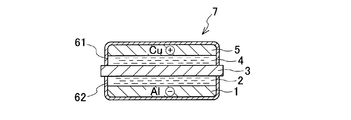
- the secondary battery 7 of this example includes a negative electrode 1, a negative electrode electrolyte 2, a diaphragm 3, a positive electrode electrolyte 4, and a positive electrode 5.
- the negative electrode 1 is made of plate-like metal aluminum.
- the electrolytic solution 2 for the negative electrode is an organic electrolytic solution, and is composed of the ethylmethylimidazolium salt shown in the above “chemical formula 1”.
- the diaphragm 3 has a film shape with a thickness of 0.15 mm.
- the diaphragm 3 is a solid electrolyte that allows only aluminum ions to pass through.
- a polymer type aluminum ion conductor is used.
- the specific structure of the polymer-type aluminum ion conductor is as follows. Polyethylene oxide is dissolved in ethanol in which Al 2 (WO 4 ) 3 powder is dispersed, and then dropped onto an aluminum disk having a diameter of 30 mm and a thickness of 5 mm. Then, a mixed thin film composed of polyethylene oxide and Al 2 (WO 4 ) 3 is formed on the surface of the aluminum disk.
- the electrolyte 4 on the positive electrode side is a water-soluble electrolyte and is composed of a 2 mol / L Al (NO 3 ) 3 aqueous solution.
- the positive electrode 5 is made of metallic copper.
- the secondary battery 7 is a coin-type battery.
- the secondary battery 7 includes cases 61 and 62.
- the negative electrode 1, the negative electrode electrolyte 2, the diaphragm 3, the positive electrode electrolyte 4, and the positive electrode 5 are provided.
- the cases 61 and 62 are made of glass and have a shape in which the coin shape is divided in half in the axial center.
- the case 62 contains a negative electrode 1 and an electrolyte solution 2 for the negative electrode.
- the electrolyte 2 for negative electrode is impregnated in the porous body.
- the porous body is a polypropylene / polyethylene nonwoven fabric having a thickness of 10 ⁇ m.
- the positive electrode 5 and the electrolyte solution 4 for positive electrode are accommodated inside the case 61.
- a diaphragm 3 is disposed between the cases 61 and 62.
- the periphery of the diaphragm 3 is airtightly clamped and fixed by a flange portion formed on the opening periphery of the cases 61 and 62.
- Each of the negative electrode 1 and the positive electrode 5 is connected to a wiring (not shown) so that electricity is led out to the outside.
- the copper on the surface of the positive electrode 5 made of metallic copper dissolves (Cu ⁇ Cu 2+ + 2e ⁇ ).
- Cu 2+ is released into the electrolyte solution 4 for the positive electrode and is ion-exchanged with Al (NO 3 ) 3 contained therein to generate Al 3+ (3Cu 2+ + 2Al (NO 3 ) 3 ⁇ 3Cu (NO 3). ) 2 + 2Al 3+ ).
- Al 3+ moves to the electrolyte solution 2 on the negative electrode side through the diaphragm 3 made of a solid electrolyte that allows only aluminum ions to pass through.
- Aluminum is deposited on the surface of the negative electrode 1 (Al 3+ + 3e ⁇ ⁇ Al).
- Al 3+ passes through the diaphragm 3 and moves to the electrolyte solution 4 on the positive electrode side.
- Al 3+ is ion-exchanged with Cu (NO 3 ) 2 present in the electrolyte 4 on the positive electrode side to generate Cu 2+ (2Al 3+ + 3Cu (NO 3 ) 2 ⁇ 3Cu 2+ + 2Al (NO 3 ) 3 ) .
- Copper is deposited on the surface of the positive electrode 5 (Cu 2+ + 2e ⁇ ⁇ Cu).
- the element constituting the negative electrode material is aluminum.
- the oxidation-reduction potential of hydrogen is 0, the oxidation-reduction potential of aluminum is ⁇ 1.68 V, which is relatively close to the oxidation-reduction potential of lithium metal, ⁇ 3.045 V. For this reason, the electromotive force of a battery can be enlarged.
- the volume density of the aluminum is the anode material is 2.7 g / cm 3, greater than the volume density of 0.534 g / cm 3 of the lithium metal. For this reason, the battery capacity per unit volume is increased, and the volume energy density of the battery can be increased.
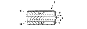
- the negative electrode material constituting the negative electrode 1 is magnesium metal.
- the electrolyte solution 2 for the negative electrode is formed by dissolving Grignard reagent C 4 H 9 MgCl in tetrahydrofuran (THF) as an organic solvent.
- the concentration of magnesium ions in the electrolytic solution 2 was adjusted to be 0.25 mol / L.
- the Grignard reagent is a dinuclear complex composed of a dimer having Mg as a nucleus. Since this binuclear complex has an electric charge, it can give high electroconductivity to electrolyte solution.
- the diaphragm 3 has a film shape with a thickness of 0.15 mm.
- the diaphragm 3 is a solid electrolyte that allows only magnesium ions to pass through.
- a polymer type magnesium ion conductor is used.
- magnesium perchlorate anhydrous Mg (C10 4 ) 2 was dissolved.
- the molar ratio (Mg / EO) of the magnesium salt (Mg) content to the content of alkylene oxide units (hereinafter abbreviated as EO) of the polyether compound was 1/32 to 1/128.
- 0.2% by weight of 2,2-dimethoxy-2-phenylacetophenone as a photopolymerization initiator was added to this composition to obtain a uniform solution.
- This solution was cast on an aluminum petri dish and irradiated with ultraviolet light for 15 minutes using a 6 W ultraviolet lamp to effect radical polymerization, thereby curing the composition.
- a colorless and transparent thin film (thickness 0.5 mm) having a uniform composition was obtained.
- This thin film is a polymer type magnesium ion conductor.
- the electrolyte 4 on the positive electrode side is a water-soluble electrolyte and is composed of a 2 mol / L Mg (NO 3 ) 2 aqueous solution.
- the positive electrode 5 is made of metallic copper.
- the copper on the surface of the positive electrode 5 made of metallic copper dissolves (Cu ⁇ Cu 2+ + 2e ⁇ ).
- Cu 2+ is released into the electrolyte 4 for the positive electrode and ion-exchanged with Mg (NO 3 ) 2 contained therein to generate Mg 2+ (Cu 2+ + Mg (NO 3 ) 2 ⁇ Cu (NO 3). ) 2 + Mg 2+ ).
- Mg 2+ passes through the diaphragm 3 made of a solid electrolyte that passes only magnesium ions, moves to the electrolyte solution 2 on the negative electrode side, and magnesium is deposited on the surface of the negative electrode 1 (Mg 2+ + 2e ⁇ ⁇ Mg).
- magnesium on the surface of the negative electrode 1 made of metallic magnesium is dissolved in the electrolyte solution 2 on the negative electrode side (Mg ⁇ Mg 2+ + 2e ⁇ ). Accordingly, Mg 2+ passes through the diaphragm 3 and moves to the electrolyte solution 4 on the positive electrode side. Mg 2+ is ion-exchanged with Cu (NO 3 ) 2 present in the electrolyte 4 on the positive electrode side to generate Cu 2+ (Mg 2+ + Cu (NO 3 ) 2 ⁇ Cu 2+ + Mg (NO 3 ) 2 ). . Copper is deposited on the surface of the positive electrode 5 (Cu 2+ + 2e ⁇ ⁇ Cu).
- the element constituting the negative electrode material is magnesium.
- the oxidation-reduction potential of hydrogen is 0, the oxidation-reduction potential of magnesium is -2.363 V, which is relatively close to the oxidation-reduction potential of lithium metal -3.045 V. For this reason, the electromotive force of a battery can be enlarged.
- the volume density of magnesium which is a negative electrode material is 1.783 g / cm 3 , which is larger than the volume density of lithium metal, 0.534 g / cm 3 . For this reason, the battery capacity per unit volume is increased, and the volume energy density of the battery can be increased.
- Example 3 As shown in FIG. 5, in the secondary battery 7 of this example, metallic calcium is used as the negative electrode 1.
- the electrolytic solution 2 for the negative electrode is an organic electrolytic solution, and is obtained by dissolving 1 mol / L Ca (ClO 4 ) 2 in an organic solvent.
- the organic solvent is made of propylene carbonate.
- the diaphragm 3 has a film shape with a thickness of 0.15 mm.
- the diaphragm 3 is a solid electrolyte that allows only calcium ions to pass through.
- a polymer type calcium ion conductor is used.
- a specific configuration of the polymer calcium ion conductor is a polymer electrolyte in which 10 parts by weight of Ca (ClO 4 ) 2 is added to polyethylene oxide (PEO).
- the electrolyte solution 4 on the positive electrode side is a water-soluble electrolyte solution and is composed of a 2 mol / L Ca (NO 3 ) 2 aqueous solution.
- the positive electrode 5 is made of metallic copper.
- the copper on the surface of the positive electrode 5 made of metallic copper dissolves (Cu ⁇ Cu 2+ + 2e ⁇ ).
- Cu 2+ is released into the electrolyte solution 4 for the positive electrode and is ion-exchanged with Ca (NO 3 ) 2 contained therein to generate Ca 2+ (Cu 2+ + Ca (NO 3 ) 2 ⁇ Cu (NO 3). ) 2 + Ca 2+ ).
- Ca 2+ moves to the electrolyte solution 2 on the negative electrode side through the diaphragm 3 made of a solid electrolyte that allows only calcium ions to pass through. Calcium precipitates on the surface of the negative electrode 1 (Ca 2+ + 2e ⁇ ⁇ Ca).
- the element constituting the negative electrode material is calcium.
- the oxidation-reduction potential of hydrogen is 0, the oxidation-reduction potential of calcium is -2.87V, which is relatively close to the oxidation-reduction potential of lithium metal -3.045V. For this reason, the electromotive force of a battery can be enlarged.
- the volume density of the calcium is negative electrode material is 1.55 g / cm 3, greater than the volume density of 0.534 g / cm 3 of the lithium metal. For this reason, the battery capacity per unit volume is increased, and the volume energy density of the battery can be increased.
- Example 4 As shown in FIG. 6, in the secondary battery 7 of this example, metallic sodium is used as the negative electrode 1.
- the electrolytic solution 2 for the negative electrode is an organic electrolytic solution, and is formed by dissolving 1 mol / L NaClO 4 in an organic solvent.
- the organic solvent is a mixture of ethylene carbonate (EC) and diethyl carbonate (DEC) at a volume ratio of 1: 1.
- the diaphragm 3 has a film shape with a thickness of 0.15 mm.
- the diaphragm 3 is a solid electrolyte that passes only sodium ions, and NASICON is used in this example.
- the specific composition of NASICON is Na 4 Zr 2 Si 3 O 12 .
- the electrolyte solution 4 on the positive electrode side is a water-soluble electrolyte solution, and consists of a 2 mol / L NaNO 3 aqueous solution.
- the positive electrode 5 is made of metallic copper.
- the copper on the surface of the positive electrode 5 made of metallic copper dissolves (Cu ⁇ Cu 2+ + 2e ⁇ ).
- Cu 2+ is released into the electrolyte solution 4 for the positive electrode, and ion exchange is performed with NaNO 3 contained therein to generate Ca 2+ (Cu 2+ + 2NaNO 3 ⁇ Cu (NO 3 ) 2 + 2Na + ).
- Na + moves through the diaphragm 3 made of a solid electrolyte that allows only sodium ions to pass through to the electrolyte 2 on the negative electrode side.
- Sodium is deposited on the surface of the negative electrode 1 (Na + + e ⁇ ⁇ Na).
- Na + passes through the diaphragm 3 and moves to the electrolyte 4 on the positive electrode side.
- Na + is ion-exchanged with Cu (NO 3 ) 2 present in the electrolyte 4 on the positive electrode side to generate Cu 2+ (2Na + + Cu (NO 3 ) 2 ⁇ Cu 2+ + 2NaNO 3 ).
- Calcium is deposited on the surface of the positive electrode 5 (Cu 2+ + 2e ⁇ ⁇ Cu).
- the element constituting the negative electrode material is sodium.
- the redox potential of hydrogen is 0, the redox potential of sodium is -2.714V, which is relatively close to the redox potential of lithium metal -3.045V. For this reason, the electromotive force of a battery can be enlarged.
- the volume density of sodium which is a negative electrode material is 0.968 g / cm ⁇ 3 >, and is larger than the volume density of lithium metal 0.534 g / cm ⁇ 3 >. For this reason, the battery capacity per unit volume is increased, and the volume energy density of the battery can be increased.
Landscapes
- Chemical & Material Sciences (AREA)
- Chemical Kinetics & Catalysis (AREA)
- Electrochemistry (AREA)
- General Chemical & Material Sciences (AREA)
- Engineering & Computer Science (AREA)
- Manufacturing & Machinery (AREA)
- Battery Electrode And Active Subsutance (AREA)
- Secondary Cells (AREA)
- Cell Electrode Carriers And Collectors (AREA)
Description

負極材料に用いられる金属元素がアルミニウムである場合には、負極材料は、アルミニウム金属又はアルミニウム合金からなるとよい。隔膜は、アルミニウムイオンのみを通す固体電解質からなるとよい。固体電解質は、NASICON型アルミニウム伝導体、β―Fe2(SO4)型アルミニウムイオン伝導体、及び高分子型アルミニウムイオン伝導体から選ばれた少なくとも一種からなることが好ましい。また、負極用の電解液は、エチルメチルイミダゾリウム塩に代表されるイオン液体を好適に用いることが可能である。この場合は必ずしも、イオン液体は有機溶媒に溶解したうえで用いる必要はない。エチルメチルイミダゾリウム塩としては、「化1」に示す化合物を用いることができる。

負極に用いられる金属元素がマグネシウムである場合には、負極材料は、マグネシウム金属又はマグネシウム合金からなるとよい。隔膜は、マグネシウムイオンのみを通す固体電解質からなるとよい。この場合、固体電解質は、β―Fe2(SO4)型マグネシウムイオン伝導体、高分子型マグネシウムイオン伝導体、及びNASICON型マグネシウム伝導体から選ばれた少なくとも一種からなるとよい。
負極材料に用いられる金属元素がカルシウムである場合、負極材料は、カルシウム金属又はカルシウム合金からなるとよい。隔膜は、カルシウムイオンのみを通す固体電解質からなるとよい。固体電解質は、β―Fe2(SO4)型カルシウムイオン伝導体、NASICON型カルシウムイオン伝導体(NASICON)、高分子型カルシウムイオン伝導体から選ばれた少なくとも一種からなるとよい。電解液は、電解質としてCa(ClO4)2を含むとよい。電解液に含まれる有機溶媒は、公知のものを用いることができる。例えば、プロピレンカーボネート、テトラヒドロフラン、ジメチルスルホキシド、γ-ブチロラクトン、1,3-ジオキソラン、4-メチル-1,3-ジオキソラン、1,2-ジメトキシエタン、2-メチルテトラヒドロフラン、スルホラン、ジエチルカーボネート、ジメチルホルムアミド、アセトニトリル、ジメチルカーボネート、エチレンカーボネート等が挙げられる。これら有機溶媒は、単独でもよいが、組み合わせて使用してもよい。
負極材料に用いられる金属元素がナトリウムである場合、負極材料は、ナトリウム金属又はナトリウム合金からなるとよい。隔膜は、ナトリウムイオンのみを通す固体電解質であるとよい。固体電解質は、NASICON、β―Fe2(SO4)型ナトリウムイオン伝導体、高分子型ナトリウムイオン伝導体から選ばれた少なくとも一種からなるとよい。電解液は、電解質としてNaClO4を含むとよい。電解液に含まれる有機溶媒は、公知のものを用いることができ、また、上記の負極材料に用いられる金属元素がカルシウムである場合と同様のものを用いることが可能である。即ち、電解液に含まれる有機溶媒は、公知のものを用いることができる。例えば、プロピレンカーボネート、テトラヒドロフラン、ジメチルスルホキシド、γ-ブチロラクトン、1,3-ジオキソラン、4-メチル-1,3-ジオキソラン、1,2-ジメトキシエタン、2-メチルテトラヒドロフラン、スルホラン、ジエチルカーボネート、ジメチルホルムアミド、アセトニトリル、ジメチルカーボネート、エチレンカーボネート等が挙げられる。これら有機溶媒は、単独でもよいが、組み合わせて使用してもよい。
このうち、エチレンカーボネートとジエチルカーボネートを用いることが好ましい。
本例の二次電池7は、図3に示すように、負極1と、負極用の電解液2と、隔膜3と、正極用の電解液4と、正極5とを備えている。負極1は、板状の金属アルミニウムからなる。負極用の電解液2は、有機電解液であり、上記「化1」に示したエチルメチルイミダゾリウム塩からなる。
図4に示すように、本例の二次電池7においては、負極1を構成する負極材料が金属マグネシウムである。
図5に示すように、本例の二次電池7においては、負極1として、金属カルシウムを用いている。負極用の電解液2は、有機電解液であり、1mol/LのCa(ClO4)2を有機溶媒に溶解してなる。有機溶媒は、プロピレンカーボネートからなる。
図6に示すように、本例の二次電池7においては、負極1として、金属ナトリウムを用いている。負極用の電解液2は、有機電解液であり、1mol/LのNaClO4を有機溶媒に溶解してなる。有機溶媒は、エチレンカーボネート(EC)とジエチルカーボネート(DEC)とを体積比で1:1の割合で混合したものである。
Claims (15)
- 負極、負極用の電解液、隔膜、正極用の電解液および正極がその順に設けられた二次電池であって、
前記負極は、水素の酸化還元電位に対して1.5V以上卑の酸化還元電位を有する元素をもち且つリチウム金属よりも体積密度が大きい負極材料からなり、
前記隔膜は、前記元素のイオンのみを通す固体電解質からなることを特徴とする二次電池。 - 前記元素は金属元素であり、
前記負極材料は、前記金属元素からなる金属又は前記金属元素を含む合金からなる請求項1記載の二次電池。 - 前記負極材料の体積密度は、リチウム金属の体積密度に対して2倍以上高い請求項1に記載の二次電池。
- 前記金属元素は、アルミニウム、マグネシウム、カルシウム、及びナトリウムの群から選ばれた一種からなる請求項2に記載の二次電池。
- 前記負極用の電解液は、有機電解液またはイオン液体である請求項1に記載の二次電池。
- 前記正極は、前記負極の酸化還元電位に対して1V以上貴の酸化還元電位を有する元素をもつ正極材料からなる請求項1に記載の二次電池。
- 前記金属元素はアルミニウムであり、
前記隔膜は、アルミニウムイオンのみを通す固体電解質であって、
前記固体電解質は、NASICON型アルミニウム伝導体、β―Fe2(SO4)型アルミニウムイオン伝導体、及び高分子型アルミニウムイオン伝導体から選ばれた少なくとも一種からなる請求項1に記載の二次電池。 - 前記負極用の電解液は、エチルメチルイミダゾリウム塩を含む請求項7記載の二次電池。
- 前記金属元素はマグネシウムであり、
前記隔膜は、マグネシウムイオンのみを通す固体電解質であって、
前記固体電解質は、β―Fe2(SO4)型マグネシウムイオン伝導体、高分子型マグネシウムイオン伝導体、及びNASICON型マグネシウム伝導体から選ばれた少なくとも一種からなる請求項1に記載の二次電池。 - 前記電解液は、グリニャール試薬RMgX(Rはアルキル基又はアリール基であり、Xは塩素、臭素、又はヨウ素である。)を含む請求項9記載の二次電池。
- 前記金属元素はカルシウムであり、
前記隔膜は、カルシウムイオンのみを通す固体電解質であって、
前記固体電解質は、β―Fe2(SO4)型カルシウムイオン伝導体、NASICON型カルシウム伝導体、及び高分子型カルシウムイオン伝導体から選ばれた少なくとも一種からなる請求項1に記載の二次電池。 - 前記電解液は、Ca(ClO4)2を含む請求項11記載の二次電池。
- 前記金属元素はナトリウムであり、
前記隔膜は、ナトリウムイオンのみを通す固体電解質であって、
前記固体電解質は、NASICON、β―Fe2(SO4)型ナトリウムイオン伝導体、及び高分子型ナトリウムイオン伝導体から選ばれた少なくとも一種からなる請求項1に記載の二次電池。 - 前記電解液は、NaClO4を含む請求項13記載の二次電池。
- 前記正極用の電解液は、水溶性電解液である請求項1に記載の二次電池。
Priority Applications (4)
| Application Number | Priority Date | Filing Date | Title |
|---|---|---|---|
| US14/373,105 US9444100B2 (en) | 2012-01-20 | 2012-09-21 | Secondary battery |
| DE112012005715.5T DE112012005715T5 (de) | 2012-01-20 | 2012-09-21 | Sekundärbatterie |
| JP2013554083A JP6011547B2 (ja) | 2012-01-20 | 2012-09-21 | 二次電池 |
| CN201280067381.4A CN104054210B (zh) | 2012-01-20 | 2012-09-21 | 二次电池 |
Applications Claiming Priority (2)
| Application Number | Priority Date | Filing Date | Title |
|---|---|---|---|
| JP2012010137 | 2012-01-20 | ||
| JP2012-010137 | 2012-01-20 |
Publications (1)
| Publication Number | Publication Date |
|---|---|
| WO2013108309A1 true WO2013108309A1 (ja) | 2013-07-25 |
Family
ID=48798768
Family Applications (1)
| Application Number | Title | Priority Date | Filing Date |
|---|---|---|---|
| PCT/JP2012/006031 Ceased WO2013108309A1 (ja) | 2012-01-20 | 2012-09-21 | 二次電池 |
Country Status (5)
| Country | Link |
|---|---|
| US (1) | US9444100B2 (ja) |
| JP (1) | JP6011547B2 (ja) |
| CN (1) | CN104054210B (ja) |
| DE (1) | DE112012005715T5 (ja) |
| WO (1) | WO2013108309A1 (ja) |
Cited By (8)
| Publication number | Priority date | Publication date | Assignee | Title |
|---|---|---|---|---|
| JP2014222609A (ja) * | 2013-05-13 | 2014-11-27 | 学校法人 関西大学 | アルミニウム二次電池 |
| WO2015107423A3 (ja) * | 2014-01-14 | 2015-10-29 | 住友電気工業株式会社 | 水溶液電解質ナトリウムイオン二次電池、および、これを含む充放電システム |
| JP2015222722A (ja) * | 2014-05-21 | 2015-12-10 | ショット アクチエンゲゼルシャフトSchott AG | 多層構造を有する電解質及び電気貯蔵デバイス |
| JP2018502416A (ja) * | 2014-10-28 | 2018-01-25 | ユニバーシティー オブ メリーランド,カレッジ パーク | 固体電池の界面層及びその製造方法 |
| US10756392B2 (en) | 2017-09-20 | 2020-08-25 | Kabushiki Kaisha Toshiba | Secondary battery, battery pack, and vehicle |
| JP2022500828A (ja) * | 2018-09-17 | 2022-01-04 | ブロードビット バッテリーズ オーイー | 金属電極を含む放電状態で組み立てられた再充電可能な電気化学セル |
| JP7343116B1 (ja) | 2022-03-24 | 2023-09-12 | 恒 高橋 | 二次電池 |
| JP7578253B1 (ja) | 2023-12-19 | 2024-11-06 | 恒 高橋 | 二次電池 |
Families Citing this family (11)
| Publication number | Priority date | Publication date | Assignee | Title |
|---|---|---|---|---|
| JP6563856B2 (ja) * | 2016-05-30 | 2019-08-21 | トヨタ自動車株式会社 | 二次電池システム |
| JP6873767B2 (ja) | 2017-03-17 | 2021-05-19 | 株式会社東芝 | 二次電池、電池パック及び車両 |
| JP6383038B1 (ja) | 2017-03-22 | 2018-08-29 | 株式会社東芝 | 二次電池、電池パック及び車両 |
| CN109698388B (zh) * | 2018-12-28 | 2021-02-09 | 宁波石墨烯创新中心有限公司 | 一种多阴极片电池 |
| CN113892206B (zh) * | 2019-07-04 | 2024-12-13 | 松下知识产权经营株式会社 | 电池 |
| CN110931843B (zh) * | 2019-10-28 | 2021-11-19 | 浙江锋锂新能源科技有限公司 | 一种新型的锂金属负极高电压正极的固液电池 |
| CN111244560B (zh) * | 2020-01-21 | 2023-07-11 | 中国科学院上海硅酸盐研究所 | 双金属电极二次电池 |
| CN113193226B (zh) * | 2021-04-22 | 2022-10-25 | 西安交通大学 | 一种调控二氧化钛/碳复合材料固体电解质界面膜的方法 |
| US20250062329A1 (en) * | 2023-08-15 | 2025-02-20 | SBK Solution Co., Ltd. | Secondary battery |
| TWI894602B (zh) * | 2023-08-17 | 2025-08-21 | 高橋恒 | 二次電池 |
| CN117878429B (zh) * | 2024-03-11 | 2024-07-19 | 蜂巢能源科技股份有限公司 | 一种电池及电池设计方法 |
Citations (5)
| Publication number | Priority date | Publication date | Assignee | Title |
|---|---|---|---|---|
| JP2009064730A (ja) * | 2007-09-07 | 2009-03-26 | Sony Corp | マグネシウムイオン含有非水電解液及びその製造方法、並びに電気化学デバイス |
| JP2010015782A (ja) * | 2008-07-02 | 2010-01-21 | Kyushu Univ | 全固体電池 |
| WO2010073978A1 (ja) * | 2008-12-26 | 2010-07-01 | 独立行政法人産業技術総合研究所 | リチウム二次電池 |
| JP2011081971A (ja) * | 2009-10-05 | 2011-04-21 | National Institute Of Advanced Industrial Science & Technology | ニッケル−リチウム二次電池 |
| JP2011228219A (ja) * | 2010-04-22 | 2011-11-10 | Toyobo Co Ltd | マグネシウム二次電池用電解質 |
Family Cites Families (19)
| Publication number | Priority date | Publication date | Assignee | Title |
|---|---|---|---|---|
| JPS5217209B2 (ja) | 1973-12-20 | 1977-05-13 | ||
| US4063005A (en) * | 1976-10-22 | 1977-12-13 | The United States Of America As Represented By The United States Energy Research And Development Administration | Cathode for molten salt batteries |
| DE2923688A1 (de) * | 1978-06-13 | 1980-01-10 | Hitachi Maxell | Lecksicheres alkalisches element und verfahren zu seiner herstellung |
| US4427747A (en) * | 1982-01-28 | 1984-01-24 | Diamond Shamrock Corporation | Bronze suppression in an alkali metal/sulfur ammonia battery |
| US4968393A (en) | 1988-04-18 | 1990-11-06 | A. L. Sandpiper Corporation | Membrane divided aqueous-nonaqueous system for electrochemical cells |
| KR100429115B1 (ko) * | 2000-09-29 | 2004-04-29 | 가부시끼가이샤 도시바 | 알루미늄을 음극에 사용한 전지 |
| US20060088763A1 (en) * | 2004-05-17 | 2006-04-27 | Wen Li | Additives for increasing ion conductivity of molten salt type electrolyte in battery |
| JP2008060552A (ja) * | 2006-08-02 | 2008-03-13 | Osaka Univ | 電子回路装置とその製造方法 |
| US8012633B2 (en) | 2006-10-13 | 2011-09-06 | Ceramatec, Inc. | Advanced metal-air battery having a ceramic membrane electrolyte |
| JP2008293678A (ja) * | 2007-05-22 | 2008-12-04 | Doshisha | 半電池および該半電池を用いた空気二次電池 |
| EP2023434B1 (de) * | 2007-07-23 | 2016-09-07 | Litarion GmbH | Elektrolytzubereitungen für Energiespeicher auf Basis ionischer Flüssigkeiten |
| JP2009230899A (ja) | 2008-03-19 | 2009-10-08 | Sanyo Electric Co Ltd | 非水電解質二次電池及びその製造方法 |
| WO2010091075A2 (en) * | 2009-02-03 | 2010-08-12 | Ceramatec, Inc. | Electrochemical cell comprising ionically conductive ceramic membrane and porous multiphase electrode |
| US8221948B2 (en) * | 2009-02-06 | 2012-07-17 | Xerox Corporation | Toner compositions and processes |
| KR101908322B1 (ko) | 2009-11-05 | 2018-10-17 | 세라마테크, 인코오포레이티드 | 나트륨 이온 전도성 세라믹 분리판을 갖는 고체-상태 나트륨계 2차 전지 |
| CN103155257B (zh) * | 2010-08-18 | 2016-08-17 | 麻省理工学院 | 固定的流体氧化还原电极 |
| US20120082904A1 (en) * | 2010-09-30 | 2012-04-05 | Brown Gilbert M | High energy density aluminum battery |
| CN102082263B (zh) | 2011-01-02 | 2013-04-03 | 浙江大学 | 导电碳膜包覆钙或钙锡合金的锂电池负极材料的制备方法 |
| US8822071B2 (en) * | 2011-10-26 | 2014-09-02 | Toyota Motor Engineering & Manufacturing North America, Inc. | Active material for rechargeable battery |
-
2012
- 2012-09-21 WO PCT/JP2012/006031 patent/WO2013108309A1/ja not_active Ceased
- 2012-09-21 JP JP2013554083A patent/JP6011547B2/ja not_active Expired - Fee Related
- 2012-09-21 US US14/373,105 patent/US9444100B2/en not_active Expired - Fee Related
- 2012-09-21 DE DE112012005715.5T patent/DE112012005715T5/de not_active Withdrawn
- 2012-09-21 CN CN201280067381.4A patent/CN104054210B/zh not_active Expired - Fee Related
Patent Citations (5)
| Publication number | Priority date | Publication date | Assignee | Title |
|---|---|---|---|---|
| JP2009064730A (ja) * | 2007-09-07 | 2009-03-26 | Sony Corp | マグネシウムイオン含有非水電解液及びその製造方法、並びに電気化学デバイス |
| JP2010015782A (ja) * | 2008-07-02 | 2010-01-21 | Kyushu Univ | 全固体電池 |
| WO2010073978A1 (ja) * | 2008-12-26 | 2010-07-01 | 独立行政法人産業技術総合研究所 | リチウム二次電池 |
| JP2011081971A (ja) * | 2009-10-05 | 2011-04-21 | National Institute Of Advanced Industrial Science & Technology | ニッケル−リチウム二次電池 |
| JP2011228219A (ja) * | 2010-04-22 | 2011-11-10 | Toyobo Co Ltd | マグネシウム二次電池用電解質 |
Cited By (10)
| Publication number | Priority date | Publication date | Assignee | Title |
|---|---|---|---|---|
| JP2014222609A (ja) * | 2013-05-13 | 2014-11-27 | 学校法人 関西大学 | アルミニウム二次電池 |
| WO2015107423A3 (ja) * | 2014-01-14 | 2015-10-29 | 住友電気工業株式会社 | 水溶液電解質ナトリウムイオン二次電池、および、これを含む充放電システム |
| JP2015222722A (ja) * | 2014-05-21 | 2015-12-10 | ショット アクチエンゲゼルシャフトSchott AG | 多層構造を有する電解質及び電気貯蔵デバイス |
| JP2018502416A (ja) * | 2014-10-28 | 2018-01-25 | ユニバーシティー オブ メリーランド,カレッジ パーク | 固体電池の界面層及びその製造方法 |
| US10756392B2 (en) | 2017-09-20 | 2020-08-25 | Kabushiki Kaisha Toshiba | Secondary battery, battery pack, and vehicle |
| JP2022500828A (ja) * | 2018-09-17 | 2022-01-04 | ブロードビット バッテリーズ オーイー | 金属電極を含む放電状態で組み立てられた再充電可能な電気化学セル |
| JP7343116B1 (ja) | 2022-03-24 | 2023-09-12 | 恒 高橋 | 二次電池 |
| JP2023141529A (ja) * | 2022-03-24 | 2023-10-05 | 恒 高橋 | 二次電池 |
| JP7578253B1 (ja) | 2023-12-19 | 2024-11-06 | 恒 高橋 | 二次電池 |
| JP2025097873A (ja) * | 2023-12-19 | 2025-07-01 | 恒 高橋 | 二次電池 |
Also Published As
| Publication number | Publication date |
|---|---|
| CN104054210B (zh) | 2016-04-27 |
| CN104054210A (zh) | 2014-09-17 |
| JPWO2013108309A1 (ja) | 2015-05-11 |
| JP6011547B2 (ja) | 2016-10-19 |
| DE112012005715T5 (de) | 2014-11-06 |
| US9444100B2 (en) | 2016-09-13 |
| US20140356731A1 (en) | 2014-12-04 |
Similar Documents
| Publication | Publication Date | Title |
|---|---|---|
| JP6011547B2 (ja) | 二次電池 | |
| Blázquez et al. | A practical perspective on the potential of rechargeable Mg batteries | |
| Wang et al. | Stabilization perspective on metal anodes for aqueous batteries | |
| Leong et al. | Reversibility of a high-voltage, Cl–-regulated, aqueous mg metal battery enabled by a water-in-salt electrolyte | |
| KR101495938B1 (ko) | 마그네슘 이온 함유 비수 전해액 및 그 제조 방법, 및 전기 화학 디바이스 | |
| Selvakumaran et al. | A review on recent developments and challenges of cathode materials for rechargeable aqueous Zn-ion batteries | |
| Yang et al. | Rechargeable sodium‐based hybrid metal‐ion batteries toward advanced energy storage | |
| CN102047491B (zh) | 包含镁离子的非水电解液以及使用该非水电解液的电化学装置 | |
| JP5158150B2 (ja) | 金属空気電池用空気極、及び当該空気極を備える金属空気電池 | |
| US8691434B2 (en) | Magnesium ion-containing non-aqueous electrolyte and a production process thereof, as well as electrochemical device | |
| JP5909024B2 (ja) | マグネシウム電池用の電解液及びそれを含むマグネシウム電池 | |
| JP5076321B2 (ja) | 電池 | |
| JP5621416B2 (ja) | 金属空気電池用発電要素及びその製造方法、並びに金属空気電池 | |
| CN105594028A (zh) | 锂锰复合氧化物、二次电池、电子设备以及制造层的方法 | |
| CN103081217A (zh) | 空气极、金属空气电池和金属空气电池用空气极的制造方法 | |
| CN109314240A (zh) | 水系二次电池 | |
| JP2012084379A (ja) | 金属空気電池システム、及び金属空気電池の充電方法 | |
| Wang et al. | Progress on aqueous rechargeable aluminium metal batteries | |
| JP2017010865A (ja) | 二次電池 | |
| JP2007188694A (ja) | 電気化学デバイス | |
| CN105870442B (zh) | 电化学能存储装置 | |
| JP2016192279A (ja) | 水系擬似固体二次電池 | |
| WO2016044857A1 (en) | Metal air energy storage device | |
| Xue et al. | Emerging Battery Systems with Metal as Active Cathode Material | |
| Zhang et al. | Sacrificial Co-solvent Electrolyte to Construct a Stable Solid Electrolyte Interphase in Lithium–Oxygen Batteries |
Legal Events
| Date | Code | Title | Description |
|---|---|---|---|
| WWE | Wipo information: entry into national phase |
Ref document number: 201280067381.4 Country of ref document: CN |
|
| 121 | Ep: the epo has been informed by wipo that ep was designated in this application |
Ref document number: 12866044 Country of ref document: EP Kind code of ref document: A1 |
|
| ENP | Entry into the national phase |
Ref document number: 2013554083 Country of ref document: JP Kind code of ref document: A |
|
| WWE | Wipo information: entry into national phase |
Ref document number: 14373105 Country of ref document: US |
|
| WWE | Wipo information: entry into national phase |
Ref document number: 1120120057155 Country of ref document: DE Ref document number: 112012005715 Country of ref document: DE |
|
| 122 | Ep: pct application non-entry in european phase |
Ref document number: 12866044 Country of ref document: EP Kind code of ref document: A1 |