WO2013105239A1 - モータ回転方向検出方法、および、モータ駆動回路 - Google Patents
モータ回転方向検出方法、および、モータ駆動回路 Download PDFInfo
- Publication number
- WO2013105239A1 WO2013105239A1 PCT/JP2012/050408 JP2012050408W WO2013105239A1 WO 2013105239 A1 WO2013105239 A1 WO 2013105239A1 JP 2012050408 W JP2012050408 W JP 2012050408W WO 2013105239 A1 WO2013105239 A1 WO 2013105239A1
- Authority
- WO
- WIPO (PCT)
- Prior art keywords
- level
- motor
- rotor
- hall element
- rotation direction
- Prior art date
- Legal status (The legal status is an assumption and is not a legal conclusion. Google has not performed a legal analysis and makes no representation as to the accuracy of the status listed.)
- Ceased
Links
Images


Classifications
-
- H—ELECTRICITY
- H02—GENERATION; CONVERSION OR DISTRIBUTION OF ELECTRIC POWER
- H02P—CONTROL OR REGULATION OF ELECTRIC MOTORS, ELECTRIC GENERATORS OR DYNAMO-ELECTRIC CONVERTERS; CONTROLLING TRANSFORMERS, REACTORS OR CHOKE COILS
- H02P6/00—Arrangements for controlling synchronous motors or other dynamo-electric motors using electronic commutation dependent on the rotor position; Electronic commutators therefor
- H02P6/14—Electronic commutators
- H02P6/16—Circuit arrangements for detecting position
-
- H—ELECTRICITY
- H02—GENERATION; CONVERSION OR DISTRIBUTION OF ELECTRIC POWER
- H02P—CONTROL OR REGULATION OF ELECTRIC MOTORS, ELECTRIC GENERATORS OR DYNAMO-ELECTRIC CONVERTERS; CONTROLLING TRANSFORMERS, REACTORS OR CHOKE COILS
- H02P6/00—Arrangements for controlling synchronous motors or other dynamo-electric motors using electronic commutation dependent on the rotor position; Electronic commutators therefor
- H02P6/30—Arrangements for controlling the direction of rotation
Definitions
- the present invention relates to a motor rotation direction detection method and a motor drive circuit.
- a U-phase Hall element H2 that detects a U-phase magnetic pole of the rotor R
- a V-phase Hall element H3 that detects a V-phase magnetic pole of the rotor R
- the rotation direction of the brushless motor M is detected by using three hall elements of the W-phase hall element H1 for detecting the W-phase magnetic pole of the rotor R (FIG. 5).
- This conventional motor rotation direction detection method is based on the change of the rotational position of the rotor R based on the levels (“Hi” level or “Lo” level) of the three pulse signals output by the three Hall elements H1 to H3. That is, changes in the rotor states S1 to S6 are detected (FIG. 6).
- a motor rotation direction detection method includes: A motor rotation detection method for detecting the rotation direction of a brushless motor using only a first Hall element for detecting the magnetic pole of the first phase of the rotor and a second Hall element for detecting the magnetic pole of the second phase of the rotor. Because At the first edge of the first pulse signal output by the first Hall element in response to rotation of the rotor of the brushless motor, the second Hall element is output in response to rotation of the rotor of the brushless motor.
- the level of the second pulse signal is the first level, it is determined that the rotor is rotating in the first rotation direction; On the other hand, when the level of the second pulse signal is the second level at the first edge of the first pulse signal, the rotor rotates in the second rotation direction opposite to the first rotation direction. It is characterized in that it is rotating.
- the first edge of the first pulse signal is a rising edge
- the first level is a “Hi” level
- the second level is a “Lo” level. Good.
- the first edge of the first pulse signal is a falling edge
- the first level is a “Lo” level
- the second level is a “Hi” level. Also good.
- the brushless motor may be a three-phase braless motor.
- the control circuit includes: When the level of the second pulse signal output from the second Hall element is the first level at the first edge of the first pulse signal output from the first Hall element, the rotor is Judge that it is rotating in the first rotation direction, On the other hand, when the level of the second pulse signal is the second level at the first edge of the first pulse signal, the rotor rotates in the second rotation direction opposite to the first rotation direction. It is characterized in that it is rotating.
- the first Hall element and the second Hall element are arranged in the order of the first Hall element and the second Hall element in the first rotation direction of the rotor, in proximity to the rotor. You may do it.
- the first edge of the first pulse signal is a rising edge
- the first level is a “Hi” level
- the second level is a “Lo” level. Good.
- the first edge of the first pulse signal is a falling edge
- the first level is a “Lo” level
- the second level is a “Hi” level. Also good.
- the first rotation direction may be a normal rotation direction of the rotor, and the second rotation direction may be a reverse rotation direction of the rotor.
- the control circuit may output a signal corresponding to the detected rotation direction of the rotor to the outside.
- the first Hall element and the second Hall element may be disposed inside a stator of the brushless motor or an exterior of the brushless motor.
- the brushless motor may be a three-phase braless motor.
- the magnetic pole of the first phase is a W-phase magnetic pole
- the magnetic pole of the second phase is a U-phase magnetic pole
- the first Hall element is a W-phase Hall element
- the second hole The element may be a W-phase Hall element.
- the motor rotation direction detection method only the first Hall element that detects the magnetic pole of the first phase of the rotor and the second Hall element that detects the magnetic pole of the second phase of the rotor are used. To detect the direction of rotation of the brushless motor.
- the rotation of the brushless motor rotor is detected. Accordingly, when the level of the second pulse signal output from the second Hall element is the first level (for example, “Hi” level), the rotor rotates in the first rotation direction (forward rotation direction).
- the motor rotation direction detection method can detect the rotation direction of the rotor while reducing the number of Hall elements as compared with the conventional one.
- the yield of products can be improved by reducing the number of Hall elements.
- the manufacturing cost of the cell die system to which the motor rotation direction detection method and the motor drive circuit of the present invention are applied can be reduced.
- the motor rotation direction detection method can determine the rotation direction of the rotor by determining one state of the rotor. For this reason, it is easy to construct a system that executes this motor rotation direction detection method.
- FIG. 1 is a diagram illustrating an example of a configuration of a motor drive system according to a first embodiment which is an aspect of the present invention.
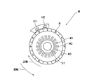
- FIG. 2 is a diagram illustrating an example of the configuration of the brushless motor illustrated in FIG. 1.
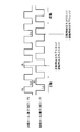
- FIG. 3 is a diagram showing the relationship between the waveforms of the first and second pulse signals shown in FIG. 1 and the rotation direction of the rotor R.
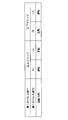
- FIG. 4 is a diagram showing the relationship between the edge of the first pulse signal and the level of the second pulse signal, and the rotation direction of the rotor R.
- FIG. 5 is a diagram showing an example of the configuration of a conventional brushless motor.
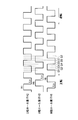
- FIG. 6 is a diagram showing the relationship between the waveform of the pulse signal output from the conventional Hall element and the rotation direction of the rotor R.
- FIG. 7 is a diagram showing the relationship between the level of the pulse signal output from the conventional Hall element and the rotation direction of the rotor R.
- the case where the brushless motor M is a three-phase braless motor will be described as an example.
- the first phase magnetic pole is a W phase magnetic pole
- the second phase magnetic pole is a U phase magnetic pole
- the first Hall element H1 is a W phase Hall element
- the second Hall element is A case where H2 is a W-phase Hall element will be described.
- the first-phase magnetic pole is a V-phase magnetic pole
- the second-phase magnetic pole is a W-phase magnetic pole
- the first Hall element H1 is a V-phase Hall element
- the second Hall element is H2 is described in the same manner even in other combinations, such as in the case of a W-phase Hall element.
- FIG. 1 is a diagram illustrating an example of a configuration of a motor drive system 100 according to a first embodiment which is an aspect of the present invention.
- FIG. 2 is a diagram showing an example of the configuration of the brushless motor M shown in FIG.
- a motor drive system 100 includes a brushless motor (three-phase braless motor) M, a motor drive circuit 1, and a first hall element (W-phase hall element) H1 provided in the brushless motor M. And a second Hall element (U-phase Hall element) H2 provided in the brushless motor M.
- the motor drive system 100 includes only two Hall elements for the three-phase brushless motor.
- the brushless motor M includes a first winding (W-phase winding) W1, a second winding (U-phase winding) W2, and a third winding (V-phase winding).
- W-phase winding W1
- U-phase winding W2
- V-phase winding V-phase winding
- Line It has the stator St provided with W3, and the rotor R.
- the first Hall element H1 and the second Hall element H2 are disposed inside the exterior of the brushless motor M. However, the first Hall element H1 and the second Hall element H2 may be disposed on the stator St.
- first Hall element H1 and the second Hall element H2 are, for example, close to the rotor R in the first rotation direction (forward rotation direction) of the rotor R.
- the Hall elements H2 are arranged in this order (FIG. 2).
- the motor drive circuit 1 detects the first Hall element H1 that detects the first phase (W phase) magnetic pole of the rotor R and the second phase that detects the second phase (U phase) magnetic pole of the rotor R.
- the rotation direction of the brushless motor M is detected using only the hall element H2.
- the motor drive circuit 1 includes a first pulse signal input terminal TP1 to which a first pulse signal P1 output from the first Hall element H1 is input according to the rotation of the rotor R of the brushless motor M, and the brushless motor M. And a second pulse signal input terminal TP2 to which a second pulse signal P2 output from the second Hall element H2 is input according to the rotation of the rotor R.
- the motor drive circuit 1 includes a motor driver D and a control circuit CON.
- the motor driver D supplies a drive current to the brushless motor M to drive the brushless motor M.
- the control circuit CON controls the brushless motor M based on the first and second pulse signals P1 and P2 output from the first Hall element H1 and the second Hall element H2 according to the rotation of the rotor R of the brushless motor M. Is detected, and the motor driver D is controlled.
- control circuit CON determines that the level of the second pulse signal P2 is the second level (for example, “Lo” level) at the first edge (for example, the falling edge) of the first pulse signal P1, for example. In this case, it is determined that the rotor R rotates in the second rotation direction (for example, the reverse direction) opposite to the first rotation direction.
- the second level for example, “Lo” level
- the rotor R rotates in the second rotation direction (for example, the reverse direction) opposite to the first rotation direction.
- the control circuit CON controls the motor driver D based on the detected rotation direction of the rotor R.
- control circuit CON outputs a signal according to the detected rotation direction of the rotor R to the outside.
- FIG. 3 is a diagram showing the relationship between the waveforms of the first and second pulse signals P1 and P2 shown in FIG.
- FIG. 4 is a diagram illustrating the relationship between the edge of the first pulse signal P1 and the level of the second pulse signal P2, and the rotation direction of the rotor R.
- the first edge (for example, the falling edge) of the first pulse signal P1 is set as the determination timing.
- the control circuit CON sets the brushless motor at the first edge (for example, the falling edge) of the first pulse signal P1 output from the first Hall element H1 according to the rotation of the rotor R of the brushless motor M.
- the level of the second pulse signal P2 output from the second Hall element H2 according to the rotation of the M rotor R is the first level ("Hi" level)
- the rotor R is in the first rotational direction. It is determined that the motor is rotating in the (forward direction) (FIG. 4).
- the second edge (for example, the rising edge) of the first pulse signal P1 may be used as the determination timing.
- the control circuit CON controls the brushless motor M at the second edge (for example, the rising edge) of the first pulse signal P1 output from the first Hall element H1 according to the rotation of the rotor R of the brushless motor M.
- the level of the second pulse signal P2 output from the second Hall element H2 in response to the rotation of the rotor R is the second level ("Lo" level)
- the rotor R moves in the first rotational direction ( It is determined that the motor rotates in the forward direction (FIG. 4).
- the control circuit CON determines that R is rotating in the second rotation direction (reverse rotation direction) (FIG. 4).
- the first Hall element H1 that detects the magnetic pole of the first phase (for example, W phase) of the rotor R and the second of the rotor R are detected.
- the rotation direction of the brushless motor M is detected using only the second Hall element H2 that detects the magnetic pole of the phase (for example, the U phase).
- the brushless motor M is detected.
- the level of the second pulse signal P2 output from the second Hall element H2 in response to the rotation of the rotor R is the first level (for example, “Hi” level)
- the rotor R is rotated in the first rotation. Judged to be rotating in the direction (forward direction).
- the motor rotation direction detection method can detect the rotation direction of the rotor R while reducing the number of Hall elements as compared with the conventional method.
- the yield of products can be improved by reducing the number of Hall elements.
- the manufacturing cost of the cell die system to which the motor rotation direction detection method and the motor drive circuit of the present invention are applied can be reduced.
- the motor rotation direction detection method can determine the rotation direction of the rotor R if one state of the rotor R is determined. For this reason, it is easy to construct a system that executes this motor rotation direction detection method.
- the first edge of the first pulse signal P1 is the rising edge
- the first level is the “Hi” level
- the second level is the “Lo” level.
- the first edge of the first pulse signal P1 is a falling edge
- the first level is the “Lo” level
- the second level is the “Hi” level. An effect can be produced.
Landscapes
- Engineering & Computer Science (AREA)
- Power Engineering (AREA)
- Control Of Motors That Do Not Use Commutators (AREA)
Description
本発明は、モータ回転方向検出方法、および、モータ駆動回路に関する。
従来、例えば、JP2008-14287Aに記載のモータ回転方向検出方法では、ロータRのU相の磁極を検出するU相ホール素子H2、ロータRのV相の磁極を検出するV相ホール素子H3、およびロータRのW相の磁極を検出するW相ホール素子H1の3つのホール素子を用いてブラシレスモータMの回転方向を検出する(図5)。
この従来のモータ回転方向検出方法は、3つの各ホール素子H1~H3が出力する3つのパルス信号のレベル(“Hi”レベルまたは“Lo”レベル)に基づいて、ロータRの回転位置の変化、すなわち、ロータ状態S1~S6の変化を検出する(図6)。
上記動作により、従来のモータ回転方向検出方法では、ロータRが正転しているか、または、反転しているかを判断する(図7)。
この従来のモータ回転方向検出方法は、高価なホール素子H1~H3を3つ使用し、これらのホール素子に接続するハーネス、端子も必要になるため、システムの製造コストが増加する問題がある。
さらに、より精度良く検出信号を出力するために、ホール素子の位置決めの精度が要求され、ホール素子の個数が多いほど製品の歩留まりが低下する問題がある。
さらに、従来のモータ回転方向検出方法では、ロータRの少なくとも2つの状態(例えば、ロータ状態S1、S2)を検出する必要があり、上記動作を実行するためのシステムの構築が困難になる問題がある。
本発明の一態様に係る実施例に従ったモータ回転方向検出方法は、
ロータの第1の相の磁極を検出する第1のホール素子および前記ロータの第2の相の磁極を検出する第2のホール素子のみを用いてブラシレスモータの回転方向を検出するモータ回転検出方法であって、
前記ブラシレスモータのロータの回転に応じて前記第1のホール素子が出力する第1のパルス信号の第1のエッジにおいて、前記ブラシレスモータのロータの回転に応じて前記第2のホール素子が出力する第2のパルス信号のレベルが第1のレベルである場合は、前記ロータが第1の回転方向に回転していると判断し、
一方、前記第1のパルス信号の前記第1のエッジにおいて、前記第2のパルス信号のレベルが第2のレベルの場合は、前記ロータが前記第1の回転方向と反対の第2の回転方向に回転していると判断する
ことを特徴とする。
ロータの第1の相の磁極を検出する第1のホール素子および前記ロータの第2の相の磁極を検出する第2のホール素子のみを用いてブラシレスモータの回転方向を検出するモータ回転検出方法であって、
前記ブラシレスモータのロータの回転に応じて前記第1のホール素子が出力する第1のパルス信号の第1のエッジにおいて、前記ブラシレスモータのロータの回転に応じて前記第2のホール素子が出力する第2のパルス信号のレベルが第1のレベルである場合は、前記ロータが第1の回転方向に回転していると判断し、
一方、前記第1のパルス信号の前記第1のエッジにおいて、前記第2のパルス信号のレベルが第2のレベルの場合は、前記ロータが前記第1の回転方向と反対の第2の回転方向に回転していると判断する
ことを特徴とする。
上記モータ回転方向検出方法において、
前記第1のパルス信号の前記第1のエッジは、立ち上がりエッジであり、前記第1のレベルは、“Hi”レベルであり、前記第2のレベルは、“Lo”レベルであるようにしてもよい。
前記第1のパルス信号の前記第1のエッジは、立ち上がりエッジであり、前記第1のレベルは、“Hi”レベルであり、前記第2のレベルは、“Lo”レベルであるようにしてもよい。
上記モータ回転方向検出方法において、
前記第1のパルス信号の前記第1のエッジは、立ち下がりエッジであり、前記第1のレベルは、“Lo”レベルであり、前記第2のレベルは、“Hi”レベルであるようにしてもよい。
前記第1のパルス信号の前記第1のエッジは、立ち下がりエッジであり、前記第1のレベルは、“Lo”レベルであり、前記第2のレベルは、“Hi”レベルであるようにしてもよい。
上記モータ回転方向検出方法において、
前記ブラシレスモータは、3相ブラレスモータであるようにしてもよい。
前記ブラシレスモータは、3相ブラレスモータであるようにしてもよい。
本発明の一態様に係る実施例に従ったモータ駆動回路は、
ロータの第1の相の磁極を検出する第1のホール素子および前記ロータの第2の相の磁極を検出する第2のホール素子のみを用いてブラシレスモータの回転方向を検出するモータ駆動回路であって、
前記ブラシレスモータに駆動電流を供給して、前記ブラシレスモータを駆動するモータドライバと、
前記ブラシレスモータのロータの回転に応じて前記第1のホール素子および前記第2のホール素子が出力するパルス信号に基づいて、前記ブラシレスモータの回転方向を検出するとともに、前記モータドライバを制御する制御回路と、を備え、
前記制御回路は、
前記第1のホール素子が出力する第1のパルス信号の第1のエッジにおいて、前記第2のホール素子が出力する第2のパルス信号のレベルが第1のレベルである場合は、前記ロータが第1の回転方向に回転していると判断し、
一方、前記第1のパルス信号の前記第1のエッジにおいて、前記第2のパルス信号のレベルが第2のレベルの場合は、前記ロータが前記第1の回転方向と反対の第2の回転方向に回転していると判断する
ことを特徴とする。
ロータの第1の相の磁極を検出する第1のホール素子および前記ロータの第2の相の磁極を検出する第2のホール素子のみを用いてブラシレスモータの回転方向を検出するモータ駆動回路であって、
前記ブラシレスモータに駆動電流を供給して、前記ブラシレスモータを駆動するモータドライバと、
前記ブラシレスモータのロータの回転に応じて前記第1のホール素子および前記第2のホール素子が出力するパルス信号に基づいて、前記ブラシレスモータの回転方向を検出するとともに、前記モータドライバを制御する制御回路と、を備え、
前記制御回路は、
前記第1のホール素子が出力する第1のパルス信号の第1のエッジにおいて、前記第2のホール素子が出力する第2のパルス信号のレベルが第1のレベルである場合は、前記ロータが第1の回転方向に回転していると判断し、
一方、前記第1のパルス信号の前記第1のエッジにおいて、前記第2のパルス信号のレベルが第2のレベルの場合は、前記ロータが前記第1の回転方向と反対の第2の回転方向に回転していると判断する
ことを特徴とする。
上記モータ駆動回路において、
前記第1のホール素子と前記第2のホール素子とは、前記ロータの第1の回転方向に前記ロータに近接して前記第1のホール素子、前記第2のホール素子の順に配置されているようにしてもよい。
前記第1のホール素子と前記第2のホール素子とは、前記ロータの第1の回転方向に前記ロータに近接して前記第1のホール素子、前記第2のホール素子の順に配置されているようにしてもよい。
上記モータ駆動回路において、
前記第1のパルス信号の前記第1のエッジは、立ち上がりエッジであり、前記第1のレベルは、“Hi”レベルであり、前記第2のレベルは、“Lo”レベルであるようにしてもよい。
前記第1のパルス信号の前記第1のエッジは、立ち上がりエッジであり、前記第1のレベルは、“Hi”レベルであり、前記第2のレベルは、“Lo”レベルであるようにしてもよい。
上記モータ駆動回路において、
前記第1のパルス信号の前記第1のエッジは、立ち下がりエッジであり、前記第1のレベルは、“Lo”レベルであり、前記第2のレベルは、“Hi”レベルであるようにしてもよい。
前記第1のパルス信号の前記第1のエッジは、立ち下がりエッジであり、前記第1のレベルは、“Lo”レベルであり、前記第2のレベルは、“Hi”レベルであるようにしてもよい。
上記モータ駆動回路において、
前記制御回路は、検出した前記ロータの回転方向に基づいて、前記モータドライバを制御するようにしてもよい。
前記制御回路は、検出した前記ロータの回転方向に基づいて、前記モータドライバを制御するようにしてもよい。
上記モータ駆動回路において、
前記第1の回転方向は、前記ロータの正転方向であり、前記第2の回転方向は、前記ロータの逆転方向であるようにしてもよい。
前記第1の回転方向は、前記ロータの正転方向であり、前記第2の回転方向は、前記ロータの逆転方向であるようにしてもよい。
上記モータ駆動回路において、
前記制御回路は、検出した前記ロータの回転方向に応じた信号を外部に出力するようにしてもよい。
前記制御回路は、検出した前記ロータの回転方向に応じた信号を外部に出力するようにしてもよい。
上記モータ駆動回路において、
前記第1のパルス信号が入力される第1のパルス信号入力端子と、前記第2のパルス信号が入力される第2のパルス信号入力端子と、を備えるようにしてもよい。
前記第1のパルス信号が入力される第1のパルス信号入力端子と、前記第2のパルス信号が入力される第2のパルス信号入力端子と、を備えるようにしてもよい。
上記モータ駆動回路において、
前記第1のホール素子および前記第2のホール素子は、前記ブラシレスモータのステータまたは前記ブラシレスモータの外装の内側に配置されているようにしてもよい。
前記第1のホール素子および前記第2のホール素子は、前記ブラシレスモータのステータまたは前記ブラシレスモータの外装の内側に配置されているようにしてもよい。
上記モータ駆動回路において、
前記ブラシレスモータは、3相ブラレスモータであるようにしてもよい。
前記ブラシレスモータは、3相ブラレスモータであるようにしてもよい。
上記モータ駆動回路において、
前記第1の相の磁極は、W相磁極であり、前記第2の相の磁極は、U相磁極であり、前記第1のホール素子は、W相ホール素子であり、前記第2のホール素子は、W相ホール素子であるようにしてもよい。
前記第1の相の磁極は、W相磁極であり、前記第2の相の磁極は、U相磁極であり、前記第1のホール素子は、W相ホール素子であり、前記第2のホール素子は、W相ホール素子であるようにしてもよい。
本発明の一態様に係るモータ回転方向検出方法では、ロータの第1の相の磁極を検出する第1のホール素子およびロータの第2の相の磁極を検出する第2のホール素子のみを用いてブラシレスモータの回転方向を検出する。
このモータ回転方向検出方法において、ブラシレスモータのロータの回転に応じて第1のホール素子が出力する第1のパルス信号の第1のエッジ(例えば、立ち上がりエッジ)において、ブラシレスモータのロータの回転に応じて第2のホール素子が出力する第2のパルス信号のレベルが第1のレベル(例えば、“Hi”レベル)である場合は、ロータが第1の回転方向(正転方向)に回転していると判断する。
また、このモータ回転方向検出方法において、第1のパルス信号の第1のエッジ(例えば、立ち上がりエッジ)において、第2のパルス信号のレベルが第2のレベル(例えば、“Lo”レベル)の場合は、ロータが第1の回転方向と反対の第2の回転方向(逆転方向)に回転していると判断する。
これにより、本発明の一態様に係るモータ回転方向検出方法は、ホール素子の数を従来よりも削減しつつ、ロータの回転方向を検出することができる。
したがって、高価なホール素子およびこのホール素子に接続されるべきハーネス、端子を削減するとことができる。
さらに、ホール素子の数を少なくできる分、製品の歩留まりを向上することができる。これにより、例えば、本発明のモータ回転方向検出方法およびモータ駆動回路を適用したセルダイシステムの製造コストを削減することができる。
特に、本発明の一態様に係るモータ回転方向検出方法は、ロータの1つの状態を判断すれば、ロータの回転方向を判断することができる。このため、このモータ回転方向検出方法を実行するシステムの構築が容易になる。
以下、本発明に係る各実施例について図面に基づいて説明する。
なお、実施例では、一例として、ブラシレスモータMが3相ブラレスモータである場合について説明する。特に、第1の相の磁極は、W相磁極であり、第2の相の磁極は、U相磁極であり、第1のホール素子H1は、W相ホール素子であり、第2のホール素子H2は、W相ホール素子である場合について説明する。しかし、第1の相の磁極は、V相磁極であり、第2の相の磁極は、W相磁極であり、第1のホール素子H1は、V相ホール素子であり、第2のホール素子H2は、W相ホール素子である場合等、他の組み合わせであっても、同様に説明される。
図1は、本発明の一態様である実施例1に係るモータ駆動システム100の構成の一例を示す図である。また、図2は、図1に示すブラシレスモータMの構成の一例を示す図である。
図1に示すように、モータ駆動システム100は、ブラシレスモータ(3相ブラレスモータ)Mと、モータ駆動回路1と、ブラシレスモータMに設けられた第1のホール素子(W相ホール素子)H1と、ブラシレスモータMに設けられた第2のホール素子(U相ホール素子)H2と、を備えている。
すなわち、モータ駆動システム100は、3相ブラシレスモータに対して2つのホール素子のみを備える。
ここで、図2に示すように、ブラシレスモータMは、第1の巻線(W相巻線)W1、第2の巻線(U相巻線)W2、第3の巻線(V相巻線)W3が設けられたステータStと、ロータRと、を有する。
なお、第1のホール素子H1および第2のホール素子H2は、ブラシレスモータMの外装の内側に配置されている。しかし、第1のホール素子H1および第2のホール素子H2は、ステータStに配置されていてもよい。
特に、第1のホール素子H1と第2のホール素子H2とは、例えば、ロータRの第1の回転方向(正転方向)にロータRに近接して第1のホール素子H1、第2のホール素子H2の順に配置されている(図2)。
そして、モータ駆動回路1は、ロータRの第1の相(W相)の磁極を検出する第1のホール素子H1およびロータRの第2の相(U相)の磁極を検出する第2のホール素子H2のみを用いてブラシレスモータMの回転方向を検出するようになっている。
このモータ駆動回路1は、ブラシレスモータMのロータRの回転に応じて第1のホール素子H1が出力する第1のパルス信号P1が入力される第1のパルス信号入力端子TP1と、ブラシレスモータMのロータRの回転に応じて第2のホール素子H2が出力する第2のパルス信号P2が入力される第2のパルス信号入力端子TP2と、を備える。
さらに、このモータ駆動回路1は、モータドライバDと、制御回路CONと、を備える。
モータドライバDは、ブラシレスモータMに駆動電流を供給して、ブラシレスモータMを駆動するようになっている。
制御回路CONは、ブラシレスモータMのロータRの回転に応じて第1のホール素子H1および第2のホール素子H2が出力する第1、第2のパルス信号P1、P2に基づいて、ブラシレスモータMの回転方向を検出するとともに、モータドライバDを制御するようになっている。
この制御回路CONは、例えば、第1のホール素子H1が出力する第1のパルス信号P1の第1のエッジ(例えば、立ち下がりエッジ)において、第2のホール素子H2が出力する第2のパルス信号P2のレベルが第1のレベル(例えば、“Hi”レベル)である場合は、ロータRが第1の回転方向(例えば、正転方向)に回転していると判断するようになっている。
また、制御回路CONは、例えば、第1のパルス信号P1の第1のエッジ(例えば、立ち下がりエッジ)において、第2のパルス信号P2のレベルが第2のレベル(例えば、“Lo”レベル)の場合は、ロータRが第1の回転方向と反対の第2の回転方向(例えば、反転方向)に回転していると判断するようになっている。
そして、制御回路CONは、検出したロータRの回転方向に基づいて、モータドライバDを制御するようになっている。
また、制御回路CONは、検出したロータRの回転方向に応じた信号を外部に出力するようになっている。
ここで、以上のような構成を有するモータ駆動回路1によるモータ回転検出方法の一例について説明する。
図3は、図1に示す第1、第2のパルス信号P1、P2の波形と、ロータRの回転方向との関係を示す図である。また、図4は、第1のパルス信号P1のエッジおよび第2のパルス信号P2のレベルと、ロータRの回転方向との関係を示す図である。
例えば、図3に示すように、第1のパルス信号P1の第1のエッジ(例えば、立ち下がりエッジ)を判断のタイミングとする。
この場合、制御回路CONは、ブラシレスモータMのロータRの回転に応じて第1のホール素子H1が出力する第1のパルス信号P1の第1のエッジ(例えば、立ち下がりエッジ)において、ブラシレスモータMのロータRの回転に応じて第2のホール素子H2が出力する第2のパルス信号P2のレベルが第1のレベル(“Hi”レベル)である場合は、ロータRが第1の回転方向(正転方向)に回転していると判断する(図4)。
一方、制御回路CONは、第1のパルス信号P1の第1のエッジ(例えば、立ち下がりエッジ)において、第2のパルス信号P2のレベルが第2のレベル(“Lo”レベル)の場合は、ロータRが第2の回転方向(逆転方向)に回転していると判断する(図4)。
また、図3に示すように、第1のパルス信号P1の第2のエッジ(例えば、立ち上がりエッジ)を判断のタイミングとしてもよい。
この場合、制御回路CONは、ブラシレスモータMのロータRの回転に応じて第1のホール素子H1が出力する第1のパルス信号P1の第2のエッジ(例えば、立ち上がりエッジ)において、ブラシレスモータMのロータRの回転に応じて第2のホール素子H2が出力する第2のパルス信号P2のレベルが第2のレベル(“Lo”レベル)である場合は、ロータRが第1の回転方向(正転方向)に回転していると判断する(図4)。
一方、制御回路CONは、第1のパルス信号P1の第2のエッジ(例えば、立ち上がりエッジ)において、第2のパルス信号P2のレベルが第1のレベル(“Hi”レベル)の場合は、ロータRが第2の回転方向(逆転方向)に回転していると判断する(図4)。
以上のように、本発明の一態様に係るモータ回転方向検出方法では、ロータRの第1の相(例えば、W相)の磁極を検出する第1のホール素子H1およびロータRの第2の相(例えば、U相)の磁極を検出する第2のホール素子H2のみを用いてブラシレスモータMの回転方向を検出する。
このモータ回転方向検出方法において、ブラシレスモータMのロータRの回転に応じて第1のホール素子H1が出力する第1のパルス信号P1の第1のエッジ(例えば、立ち上がりエッジ)において、ブラシレスモータMのロータRの回転に応じて第2のホール素子H2が出力する第2のパルス信号P2のレベルが第1のレベル(例えば、“Hi”レベル)である場合は、ロータRが第1の回転方向(正転方向)に回転していると判断する。
また、このモータ回転方向検出方法において、第1のパルス信号の第1のエッジ(例えば、立ち上がりエッジ)において、第2のパルス信号のレベルが第2のレベル(例えば、“Lo”レベル)の場合は、ロータRが第1の回転方向と反対の第2の回転方向(逆転方向)に回転していると判断する。
これにより、本発明の一態様に係るモータ回転方向検出方法は、ホール素子の数を従来よりも削減しつつ、ロータRの回転方向を検出することができる。
したがって、高価なホール素子およびこのホール素子に接続されるべきハーネス、端子TP1、TP2を削減するとことができる。
さらに、ホール素子の数を少なくできる分、製品の歩留まりを向上することができる。これにより、例えば、本発明のモータ回転方向検出方法およびモータ駆動回路を適用したセルダイシステムの製造コストを削減することができる。
特に、本発明の一態様に係るモータ回転方向検出方法は、ロータRの1つの状態を判断すれば、ロータRの回転方向を判断することができる。このため、このモータ回転方向検出方法を実行するシステムの構築が容易になる。
なお、既述の実施例では、第1のパルス信号P1の第1のエッジは、立ち上がりエッジであり、第1のレベルは、“Hi”レベルであり、第2のレベルは、“Lo”レベルである場合について説明した。
しかし、第1のパルス信号P1の第1のエッジは、立ち下がりエッジであり、第1のレベルは、“Lo”レベルであり、第2のレベルは、“Hi”レベルである場合も同様の作用効果を奏することができる。
なお、実施形態は例示であり、発明の範囲はそれらに限定されない。
100 モータ駆動システム
M ブラシレスモータ(3相ブラレスモータ)
1 モータ駆動回路
H1 第1のホール素子(W相ホール素子)
H2 第2のホール素子(U相ホール素子)
H3 第3のホール素子(V相ホール素子)
P1 第1のパルス信号
P2 第2のパルス信号
TP1 第1のパルス信号入力端子
TP2 第2のパルス信号入力端子
W1 第1の巻線(W相巻線)
W2 第2の巻線(U相巻線)
W3 第3の巻線(V相巻線)
R ロータ
St ステータ
M ブラシレスモータ(3相ブラレスモータ)
1 モータ駆動回路
H1 第1のホール素子(W相ホール素子)
H2 第2のホール素子(U相ホール素子)
H3 第3のホール素子(V相ホール素子)
P1 第1のパルス信号
P2 第2のパルス信号
TP1 第1のパルス信号入力端子
TP2 第2のパルス信号入力端子
W1 第1の巻線(W相巻線)
W2 第2の巻線(U相巻線)
W3 第3の巻線(V相巻線)
R ロータ
St ステータ
Claims (15)
- ロータの第1の相の磁極を検出する第1のホール素子および前記ロータの第2の相の磁極を検出する第2のホール素子のみを用いてブラシレスモータの回転方向を検出するモータ回転検出方法であって、
前記ブラシレスモータのロータの回転に応じて前記第1のホール素子が出力する第1のパルス信号の第1のエッジにおいて、前記ブラシレスモータのロータの回転に応じて前記第2のホール素子が出力する第2のパルス信号のレベルが第1のレベルである場合は、前記ロータが第1の回転方向に回転していると判断し、
一方、前記第1のパルス信号の前記第1のエッジにおいて、前記第2のパルス信号のレベルが第2のレベルの場合は、前記ロータが前記第1の回転方向と反対の第2の回転方向に回転していると判断することを特徴とするモータ回転方向検出方法。 - 前記第1のパルス信号の前記第1のエッジは、立ち上がりエッジであり、前記第1のレベルは、“Hi”レベルであり、前記第2のレベルは、“Lo”レベルであることを特徴とする請求項1に記載のモータ回転方向検出方法。
- 前記第1のパルス信号の前記第1のエッジは、立ち下がりエッジであり、前記第1のレベルは、“Lo”レベルであり、前記第2のレベルは、“Hi”レベルであることを特徴とする請求項1に記載のモータ回転方向検出方法。
- 前記ブラシレスモータは、3相ブラレスモータであることを特徴とする請求項1ないし3のいずれか一項に記載のモータ回転方向検出方法。
- ロータの第1の相の磁極を検出する第1のホール素子および前記ロータの第2の相の磁極を検出する第2のホール素子のみを用いてブラシレスモータの回転方向を検出するモータ駆動回路であって、
前記ブラシレスモータに駆動電流を供給して、前記ブラシレスモータを駆動するモータドライバと、
前記ブラシレスモータのロータの回転に応じて前記第1のホール素子および前記第2のホール素子が出力するパルス信号に基づいて、前記ブラシレスモータの回転方向を検出するとともに、前記モータドライバを制御する制御回路と、を備え、
前記制御回路は、
前記第1のホール素子が出力する第1のパルス信号の第1のエッジにおいて、前記第2のホール素子が出力する第2のパルス信号のレベルが第1のレベルである場合は、前記ロータが第1の回転方向に回転していると判断し、
一方、前記第1のパルス信号の前記第1のエッジにおいて、前記第2のパルス信号のレベルが第2のレベルの場合は、前記ロータが前記第1の回転方向と反対の第2の回転方向に回転していると判断することを特徴とするモータ駆動回路。 - 前記第1のホール素子と前記第2のホール素子とは、前記ロータの第1の回転方向に前記ロータに近接して前記第1のホール素子、前記第2のホール素子の順に配置されていることを特徴とする請求項5に記載のモータ駆動回路。
- 前記第1のパルス信号の前記第1のエッジは、立ち上がりエッジであり、前記第1のレベルは、“Hi”レベルであり、前記第2のレベルは、“Lo”レベルであることを特徴とする請求項5または6に記載のモータ駆動回路。
- 前記第1のパルス信号の前記第1のエッジは、立ち下がりエッジであり、前記第1のレベルは、“Lo”レベルであり、前記第2のレベルは、“Hi”レベルであることを特徴とする請求項5または6に記載のモータ駆動回路。
- 前記制御回路は、検出した前記ロータの回転方向に基づいて、前記モータドライバを制御することを特徴とする請求項5ないし8のいずれか一項に記載のモータ駆動回路。
- 前記第1の回転方向は、前記ロータの正転方向であり、前記第2の回転方向は、前記ロータの逆転方向であることを特徴とする請求項5ないし9のいずれか一項に記載のモータ駆動回路。
- 前記制御回路は、検出した前記ロータの回転方向に応じた信号を外部に出力することを特徴とする請求項5ないし10のいずれか一項に記載のモータ駆動回路。
- 前記第1のパルス信号が入力される第1のパルス信号入力端子と、前記第2のパルス信号が入力される第2のパルス信号入力端子と、を備えることを特徴とする請求項5ないし11のいずれか一項に記載のモータ駆動回路。
- 前記第1のホール素子および前記第2のホール素子は、前記ブラシレスモータのステータまたは前記ブラシレスモータの外装の内側に配置されていることを特徴とする請求項5ないし12のいずれか一項に記載のモータ駆動回路。
- 前記ブラシレスモータは、3相ブラレスモータであることを特徴とする請求項5ないし13のいずれか一項に記載のモータ駆動回路。
- 前記第1の相の磁極は、W相磁極であり、前記第2の相の磁極は、U相磁極であり、前記第1のホール素子は、W相ホール素子であり、前記第2のホール素子は、W相ホール素子であることを特徴とする請求項5ないし14のいずれか一項に記載のモータ駆動回路。
Priority Applications (1)
| Application Number | Priority Date | Filing Date | Title |
|---|---|---|---|
| PCT/JP2012/050408 WO2013105239A1 (ja) | 2012-01-11 | 2012-01-11 | モータ回転方向検出方法、および、モータ駆動回路 |
Applications Claiming Priority (1)
| Application Number | Priority Date | Filing Date | Title |
|---|---|---|---|
| PCT/JP2012/050408 WO2013105239A1 (ja) | 2012-01-11 | 2012-01-11 | モータ回転方向検出方法、および、モータ駆動回路 |
Publications (1)
| Publication Number | Publication Date |
|---|---|
| WO2013105239A1 true WO2013105239A1 (ja) | 2013-07-18 |
Family
ID=48781211
Family Applications (1)
| Application Number | Title | Priority Date | Filing Date |
|---|---|---|---|
| PCT/JP2012/050408 Ceased WO2013105239A1 (ja) | 2012-01-11 | 2012-01-11 | モータ回転方向検出方法、および、モータ駆動回路 |
Country Status (1)
| Country | Link |
|---|---|
| WO (1) | WO2013105239A1 (ja) |
Cited By (1)
| Publication number | Priority date | Publication date | Assignee | Title |
|---|---|---|---|---|
| WO2019198294A1 (ja) * | 2018-04-13 | 2019-10-17 | 株式会社ジャパンディスプレイ | 表示装置 |
Citations (5)
| Publication number | Priority date | Publication date | Assignee | Title |
|---|---|---|---|---|
| JPH11252887A (ja) * | 1998-03-06 | 1999-09-17 | Akebono Brake Ind Co Ltd | 電動モータ |
| JP2003319631A (ja) * | 2002-04-19 | 2003-11-07 | Asmo Co Ltd | ブラシレスモータ |
| JP2005057854A (ja) * | 2003-08-01 | 2005-03-03 | Honda Motor Co Ltd | ブラシレスモータ |
| JP2007129877A (ja) * | 2005-11-07 | 2007-05-24 | Toshiba Corp | モータ制御装置およびファンモータ |
| JP2009131105A (ja) * | 2007-11-27 | 2009-06-11 | Nidec Servo Corp | モータの駆動回路 |
-
2012
- 2012-01-11 WO PCT/JP2012/050408 patent/WO2013105239A1/ja not_active Ceased
Patent Citations (5)
| Publication number | Priority date | Publication date | Assignee | Title |
|---|---|---|---|---|
| JPH11252887A (ja) * | 1998-03-06 | 1999-09-17 | Akebono Brake Ind Co Ltd | 電動モータ |
| JP2003319631A (ja) * | 2002-04-19 | 2003-11-07 | Asmo Co Ltd | ブラシレスモータ |
| JP2005057854A (ja) * | 2003-08-01 | 2005-03-03 | Honda Motor Co Ltd | ブラシレスモータ |
| JP2007129877A (ja) * | 2005-11-07 | 2007-05-24 | Toshiba Corp | モータ制御装置およびファンモータ |
| JP2009131105A (ja) * | 2007-11-27 | 2009-06-11 | Nidec Servo Corp | モータの駆動回路 |
Cited By (1)
| Publication number | Priority date | Publication date | Assignee | Title |
|---|---|---|---|---|
| WO2019198294A1 (ja) * | 2018-04-13 | 2019-10-17 | 株式会社ジャパンディスプレイ | 表示装置 |
Similar Documents
| Publication | Publication Date | Title |
|---|---|---|
| EP3264591B1 (en) | Electric drive device, and electric power steering device | |
| WO2015136989A1 (ja) | モータ制御装置及びモータの制御方法 | |
| US20150256113A1 (en) | Motor drive system and motor control device | |
| JP6460927B2 (ja) | 電動パワーステアリング装置の制御装置及び電動パワーステアリング装置 | |
| JP6452889B2 (ja) | 電動機 | |
| CN102725954A (zh) | 用于固定在电机上的传感器单元以及电动机系统 | |
| US9000704B2 (en) | Three-phase motor driving apparatus and three-phase motor driving method | |
| CN105281616A (zh) | 基于霍尔传感器的角度校正方法、装置及永磁同步电机 | |
| US10326388B2 (en) | Lead angle controller | |
| JP2013519347A (ja) | 回路装置およびこの回路装置を動作するための方法および装置 | |
| CN104521131A (zh) | 同步电动机驱动系统 | |
| KR102270725B1 (ko) | Bldc 모터 제어시스템 및 그 제어방법 | |
| CN103606328B (zh) | 无刷直流电机霍尔信号与转子位置关系自学习方法 | |
| WO2013105239A1 (ja) | モータ回転方向検出方法、および、モータ駆動回路 | |
| JP2017073942A (ja) | モータ制御装置 | |
| JP5385044B2 (ja) | モータ制御装置およびこのモータ制御装置を備えるモータ装置 | |
| CN112953350B (zh) | 回转机械控制装置以及控制方法 | |
| JPWO2019054089A1 (ja) | モータ駆動装置、モータ、および電動パワーステアリング装置 | |
| TWI502879B (zh) | 馬達感測訊號建立方法 | |
| US20160373049A1 (en) | Apparatus for controlling motor | |
| US11205980B2 (en) | Motor driving control device | |
| CN103178759A (zh) | 一种无hall的伺服电机启动方法 | |
| KR100394690B1 (ko) | 하이브리드 전기 자동차의 비엘디씨 전동기 구동장치 | |
| JP2006033928A (ja) | ブラシレスモータ | |
| JP2005027391A (ja) | ブラシレスモータの駆動装置 |
Legal Events
| Date | Code | Title | Description |
|---|---|---|---|
| 121 | Ep: the epo has been informed by wipo that ep was designated in this application |
Ref document number: 12865308 Country of ref document: EP Kind code of ref document: A1 |
|
| NENP | Non-entry into the national phase |
Ref country code: DE |
|
| 122 | Ep: pct application non-entry in european phase |
Ref document number: 12865308 Country of ref document: EP Kind code of ref document: A1 |
|
| NENP | Non-entry into the national phase |
Ref country code: JP |