WO2013105197A1 - 超音波診断装置、および、血管検出方法 - Google Patents
超音波診断装置、および、血管検出方法 Download PDFInfo
- Publication number
- WO2013105197A1 WO2013105197A1 PCT/JP2012/008331 JP2012008331W WO2013105197A1 WO 2013105197 A1 WO2013105197 A1 WO 2013105197A1 JP 2012008331 W JP2012008331 W JP 2012008331W WO 2013105197 A1 WO2013105197 A1 WO 2013105197A1
- Authority
- WO
- WIPO (PCT)
- Prior art keywords
- blood flow
- flow region
- blood
- diagnostic apparatus
- blood vessel
- Prior art date
Links
Images


Classifications
-
- A—HUMAN NECESSITIES
- A61—MEDICAL OR VETERINARY SCIENCE; HYGIENE
- A61B—DIAGNOSIS; SURGERY; IDENTIFICATION
- A61B8/00—Diagnosis using ultrasonic, sonic or infrasonic waves
- A61B8/52—Devices using data or image processing specially adapted for diagnosis using ultrasonic, sonic or infrasonic waves
- A61B8/5215—Devices using data or image processing specially adapted for diagnosis using ultrasonic, sonic or infrasonic waves involving processing of medical diagnostic data
- A61B8/5223—Devices using data or image processing specially adapted for diagnosis using ultrasonic, sonic or infrasonic waves involving processing of medical diagnostic data for extracting a diagnostic or physiological parameter from medical diagnostic data
-
- A—HUMAN NECESSITIES
- A61—MEDICAL OR VETERINARY SCIENCE; HYGIENE
- A61B—DIAGNOSIS; SURGERY; IDENTIFICATION
- A61B8/00—Diagnosis using ultrasonic, sonic or infrasonic waves
- A61B8/06—Measuring blood flow
-
- A—HUMAN NECESSITIES
- A61—MEDICAL OR VETERINARY SCIENCE; HYGIENE
- A61B—DIAGNOSIS; SURGERY; IDENTIFICATION
- A61B8/00—Diagnosis using ultrasonic, sonic or infrasonic waves
- A61B8/08—Detecting organic movements or changes, e.g. tumours, cysts, swellings
- A61B8/0833—Detecting organic movements or changes, e.g. tumours, cysts, swellings involving detecting or locating foreign bodies or organic structures
- A61B8/085—Detecting organic movements or changes, e.g. tumours, cysts, swellings involving detecting or locating foreign bodies or organic structures for locating body or organic structures, e.g. tumours, calculi, blood vessels, nodules
-
- A—HUMAN NECESSITIES
- A61—MEDICAL OR VETERINARY SCIENCE; HYGIENE
- A61B—DIAGNOSIS; SURGERY; IDENTIFICATION
- A61B8/00—Diagnosis using ultrasonic, sonic or infrasonic waves
- A61B8/08—Detecting organic movements or changes, e.g. tumours, cysts, swellings
- A61B8/0891—Detecting organic movements or changes, e.g. tumours, cysts, swellings for diagnosis of blood vessels
-
- A—HUMAN NECESSITIES
- A61—MEDICAL OR VETERINARY SCIENCE; HYGIENE
- A61B—DIAGNOSIS; SURGERY; IDENTIFICATION
- A61B8/00—Diagnosis using ultrasonic, sonic or infrasonic waves
- A61B8/13—Tomography
-
- A—HUMAN NECESSITIES
- A61—MEDICAL OR VETERINARY SCIENCE; HYGIENE
- A61B—DIAGNOSIS; SURGERY; IDENTIFICATION
- A61B8/00—Diagnosis using ultrasonic, sonic or infrasonic waves
- A61B8/13—Tomography
- A61B8/14—Echo-tomography
-
- A—HUMAN NECESSITIES
- A61—MEDICAL OR VETERINARY SCIENCE; HYGIENE
- A61B—DIAGNOSIS; SURGERY; IDENTIFICATION
- A61B8/00—Diagnosis using ultrasonic, sonic or infrasonic waves
- A61B8/13—Tomography
- A61B8/14—Echo-tomography
- A61B8/145—Echo-tomography characterised by scanning multiple planes
-
- A—HUMAN NECESSITIES
- A61—MEDICAL OR VETERINARY SCIENCE; HYGIENE
- A61B—DIAGNOSIS; SURGERY; IDENTIFICATION
- A61B8/00—Diagnosis using ultrasonic, sonic or infrasonic waves
- A61B8/42—Details of probe positioning or probe attachment to the patient
- A61B8/4245—Details of probe positioning or probe attachment to the patient involving determining the position of the probe, e.g. with respect to an external reference frame or to the patient
- A61B8/4254—Details of probe positioning or probe attachment to the patient involving determining the position of the probe, e.g. with respect to an external reference frame or to the patient using sensors mounted on the probe
-
- A—HUMAN NECESSITIES
- A61—MEDICAL OR VETERINARY SCIENCE; HYGIENE
- A61B—DIAGNOSIS; SURGERY; IDENTIFICATION
- A61B8/00—Diagnosis using ultrasonic, sonic or infrasonic waves
- A61B8/46—Ultrasonic, sonic or infrasonic diagnostic devices with special arrangements for interfacing with the operator or the patient
- A61B8/461—Displaying means of special interest
- A61B8/466—Displaying means of special interest adapted to display 3D data
-
- A—HUMAN NECESSITIES
- A61—MEDICAL OR VETERINARY SCIENCE; HYGIENE
- A61B—DIAGNOSIS; SURGERY; IDENTIFICATION
- A61B8/00—Diagnosis using ultrasonic, sonic or infrasonic waves
- A61B8/48—Diagnostic techniques
- A61B8/483—Diagnostic techniques involving the acquisition of a 3D volume of data
-
- A—HUMAN NECESSITIES
- A61—MEDICAL OR VETERINARY SCIENCE; HYGIENE
- A61B—DIAGNOSIS; SURGERY; IDENTIFICATION
- A61B8/00—Diagnosis using ultrasonic, sonic or infrasonic waves
- A61B8/48—Diagnostic techniques
- A61B8/488—Diagnostic techniques involving Doppler signals
-
- A—HUMAN NECESSITIES
- A61—MEDICAL OR VETERINARY SCIENCE; HYGIENE
- A61B—DIAGNOSIS; SURGERY; IDENTIFICATION
- A61B8/00—Diagnosis using ultrasonic, sonic or infrasonic waves
- A61B8/52—Devices using data or image processing specially adapted for diagnosis using ultrasonic, sonic or infrasonic waves
- A61B8/5207—Devices using data or image processing specially adapted for diagnosis using ultrasonic, sonic or infrasonic waves involving processing of raw data to produce diagnostic data, e.g. for generating an image
Definitions
- the present invention relates to an ultrasonic diagnostic apparatus and a blood vessel specifying method.
- the present invention relates to an ultrasonic diagnostic apparatus and a blood vessel detection method for specifying a target blood vessel based on reflected ultrasonic waves acquired from a subject by an ultrasonic probe.
- the intima-media thickness (hereinafter referred to as IMT), which is the thickness of the intima and intima of the blood vessel wall, is measured using an ultrasonic diagnostic apparatus. Yes.
- IMT intima-media thickness
- the examiner manually designates (sketches) the shape of the outer blood vessel and the inner blood vessel in the ultrasonic image, and performs diagnosis based on the sketch. Specifically, the examiner sketches the peripheral shape of the adventitia as the adventitia contour line, and further sketches the peripheral shape of the lumen as the lumen contour line with respect to the B-mode image. Finally, based on the shape of the sketch, the inspector makes a diagnosis such as the presence or absence of plaque (see Non-Patent Document 1).
- the present invention provides an ultrasonic diagnostic apparatus that more accurately detects a blood vessel to be examined.
- An ultrasonic diagnostic apparatus is an ultrasonic diagnostic apparatus that detects a target blood vessel of a subject based on reflected ultrasound acquired from the subject by an ultrasound probe, and the reflected ultrasound A tomographic image generation unit that generates a tomographic image of the subject based on the blood flow, and a blood flow that generates blood flow information indicating a blood flow region of the subject on the tomographic image based on the reflected ultrasound A blood flow region for determining whether or not the blood flow region is a blood flow region corresponding to the target blood vessel by analyzing the blood flow information generated by the information generation unit and the blood flow information generation unit A determination unit is provided.
- the ultrasonic diagnostic apparatus of the present invention can specify a blood vessel to be examined more accurately.
- FIG. 1 is a diagram illustrating a schematic configuration of the ultrasonic diagnostic apparatus according to the first embodiment.
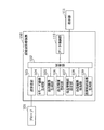
- FIG. 2 is a block diagram illustrating a detailed configuration of the ultrasonic diagnostic apparatus according to the first embodiment.
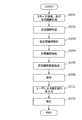
- FIG. 3 is a first example of a flowchart of a blood vessel contour extraction process of the ultrasonic diagnostic apparatus according to the first embodiment.
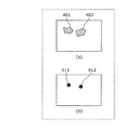
- 4A is a diagram showing a blood flow region of a blood flow image
- FIG. 4B is a diagram showing a blood flow point.
- 5A is a diagram showing a result of extracting blood flow points in a plurality of frames
- FIG. 5B is a diagram showing a result of grouping blood flow points
- FIG. 5C is a diagram corresponding to a blood flow region of the extracted target blood vessel.
- FIG. 6 is a second example of a flowchart of blood vessel contour extraction processing of the ultrasonic diagnostic apparatus according to the first embodiment.
- FIG. 7 is a block diagram illustrating a schematic configuration of the ultrasonic diagnostic apparatus according to the second embodiment.
- FIG. 8 is a block diagram illustrating a schematic configuration of the ultrasonic diagnostic apparatus according to the third embodiment.
- FIG. 9 is a flowchart of blood vessel contour extraction processing of the ultrasonic diagnostic apparatus according to the third embodiment.
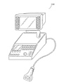
- FIG. 10 is an external view of the ultrasonic diagnostic apparatus according to each embodiment.
- FIG. 11 is a diagram illustrating a first example of an assumed ultrasonic diagnostic apparatus.
- FIG. 12 is a diagram illustrating a second example of an assumed ultrasonic diagnostic apparatus.
- an ultrasonic diagnostic apparatus has been used to detect arteriosclerosis and vascular disease at an early stage. Specifically, the intima-media thickness (hereinafter referred to as IMT), which is the thickness of the intima and intima of the blood vessel wall, is measured using an ultrasonic diagnostic apparatus. Yes. In addition, the presence or absence of plaque generated by narrowing of the lumen of a blood vessel has been confirmed using an ultrasonic diagnostic apparatus. This is because it has become clear that as the arteriosclerosis progresses, the IMT becomes thicker and plaques are formed. Arteriosclerosis is considered to progress systemically, and mainly the superficial carotid artery is a measurement target when judging the degree of progression of arteriosclerosis.
- the plaque means a raised lesion in which the inner wall of the blood vessel locally protrudes inside the blood vessel (lumen).
- Plaque takes various forms such as thrombus, fatty, and fibrous and can cause stenosis and occlusion of the carotid artery, as well as cerebral infarction and cerebral ischemia.
- ⁇ Measurement of IMT and detection of plaque shape by an ultrasonic diagnostic apparatus are performed using an ultrasonic image of a blood vessel.
- the ultrasonic diagnostic apparatus transmits ultrasonic waves into the subject from the subject surface via the probe, and forms an ultrasonic image (for example, a B-mode image) based on the reflected waves generated from the subject. Then, the examiner determines the presence or absence of plaque by looking at this ultrasonic image.
- the examiner determines the thickness of the IMT or the presence or absence of plaque
- the examiner manually designates (sketches) the shape of the epicardium and endovascular membrane in the ultrasound image, and uses this sketch. Diagnosis is originally made (for example, the configuration of FIG. 11). Specifically, the examiner sketches the peripheral shape of the adventitia as the adventitia contour line, and further sketches the peripheral shape of the lumen as the lumen contour line with respect to the B-mode image. Finally, based on the shape of the sketch, the inspector makes a diagnosis such as the presence or absence of plaque (see, for example, Non-Patent Document 1).
- Non-Patent Document 1 the examiner needs to manually specify the positions of the epicardial contour and the lumen contour of the blood vessel wall on the ultrasonic image in an offline state after image acquisition. That is, the inspector needs to manually specify the contour when performing plaque detection by the conventional diagnostic method, which is troublesome. As a result, fluctuations in the inspection results that occur depending on the inspector occur. Therefore, there is a problem that blood vessels may not be detected accurately.
- the present invention provides an ultrasonic diagnostic apparatus that more accurately detects a blood vessel to be examined.
- an ultrasonic diagnostic apparatus detects an object blood vessel of a subject based on reflected ultrasound acquired from the subject with an ultrasonic probe.
- a tomographic image generation unit that generates a tomographic image of the subject based on the reflected ultrasound; and a blood flow region of the subject on the tomographic image based on the reflected ultrasound.
- Whether the blood flow region corresponds to the target blood vessel by analyzing the blood flow information generated by the blood flow information generation unit that generates the blood flow information shown and the blood flow information generation unit
- a blood flow region determination unit for determining whether or not.
- the ultrasonic diagnostic apparatus can determine the blood flow region corresponding to the target blood vessel in the ultrasonic image based on the blood flow information regarding the blood flow region.
- a blood flow region corresponding to the target blood vessel can be specified among a plurality of blood flow regions based on the blood flow information. Therefore, the ultrasonic diagnostic apparatus can detect the blood vessel to be examined more accurately.
- the blood flow region determination unit performs the determination by analyzing the position of the blood flow region in the tomographic image as the blood flow information.
- the ultrasonic diagnostic apparatus can specify the blood flow region based on the position of the blood flow region in the ultrasonic image. Since the examiner sequentially acquires ultrasonic images while moving (scanning) the ultrasonic probe, the position of the blood flow region in the ultrasonic image is analyzed, so that the plurality of ultrasonic images correspond to the same blood vessel. A blood flow region can be detected. Therefore, the blood vessel to be examined can be detected more accurately.
- the blood flow region determination unit A plurality of blood flow regions whose distances are equal to or less than a threshold are collectively extracted as one blood flow region group, and blood flow regions included in the blood flow region group based on the extracted attributes of the blood flow region group The above determination is performed.
- the ultrasound diagnostic apparatus extracts a blood flow region where the position of the blood flow region in each of the plurality of ultrasonic images is equal to or less than the threshold value as a blood flow region (blood flow region group) corresponding to the same blood vessel.
- a blood flow region blood flow region group
- the examiner sequentially acquires ultrasonic images while moving the ultrasonic probe, blood flow regions corresponding to the same blood vessel exist in relatively close positions in a plurality of ultrasonic images acquired at relatively close times. To do.
- the blood flow region to be examined can be detected more accurately.
- the blood flow region determination unit determines that the blood flow region included in the extracted blood flow region group is the The determination that the blood flow region corresponds to the target blood vessel is performed.
- the ultrasound diagnostic apparatus corresponds to the blood flow region group to the target blood vessel. It can be specified as a blood flow region.
- the blood flow region determination unit includes the number of blood flow regions included in the extracted blood flow region group and the area of the blood flow region having the largest area among the blood flow regions included in the blood flow region group. And at least one of the position of the blood flow region in each of the tomographic images acquired from the start end and the end of the range on the subject from which the plurality of tomographic images including the blood flow region group are acquired. The determination is performed as an attribute of the blood flow region group.
- a Y-shaped blood vessel can be specified more accurately by using these attributes.
- the blood flow region having the largest area among the blood flow regions included in the blood flow region group corresponds to a Y-shaped branch, and the start and end are the start and end of scanning with an ultrasonic probe, respectively.
- the ultrasonic diagnostic apparatus can specify the Y-shaped blood vessel more accurately by specifying the Y-shaped branch portion and the end portion.
- the blood flow region determination unit includes blood flows included in the blood flow region group excluding the blood flow region group The determination is performed on the region.
- the ultrasonic diagnostic apparatus identifies a blood flow region group including a small number of blood flow regions as blood flow noise, and determines the blood flow region group identified as blood flow noise as a blood flow region. Can be excluded from the target. Therefore, the target blood vessel can be accurately detected even when there is blood flow information other than the target blood vessel such as blood flow noise.
- the blood flow region determination unit is configured such that a blood flow region included in a blood flow region group including a blood flow region having a maximum area among the blood flow region groups is a blood flow region corresponding to the target blood vessel. Judge that there is.
- the blood flow region determination unit further arranges each of the blood flow region groups in correspondence with the position of the subject from which the tomographic image including each of the extracted blood flow region groups is acquired
- the distance between the end of the figure formed by interpolating the first blood flow region group and the part of the figure formed by interpolating the second blood flow region group is less than or equal to a predetermined value
- the first blood flow region group and the second blood flow region group are collectively extracted as one blood flow region group, and the determination is performed on the newly extracted blood flow region group.
- the blood flow region determination unit further arranges each of the blood flow region groups in correspondence with a position on the subject from which the tomographic image including each of the extracted blood flow region groups is acquired.
- a first position on the tomographic image of the first blood flow region included in the tomographic image acquired from the start or end of the range on the subject corresponding to the blood flow region group, and the subject The second blood flow region on the tomographic image of the second blood flow region, which is a blood flow region included in the tomographic image acquired from the beginning or end of the range on the specimen and is different from the first blood flow region.
- the difference between the two positions is not more than a predetermined value, and the position of the subject from which the first blood flow region is acquired and the position of the subject from which the second blood flow region is acquired are not more than a predetermined distance.
- the ultrasound diagnostic apparatus determines whether or not the target blood vessel is a plurality of blood flow region groups extracted as different blood flow region groups as one blood flow region group. Can do.
- the blood flow region determination unit performs the determination by analyzing the area of the blood flow region in the tomographic image as the blood flow information.
- the ultrasonic diagnostic apparatus can specify the blood flow region based on the area of the blood flow region in the ultrasonic image. Since the examiner sequentially acquires ultrasonic images while moving (scanning) the ultrasonic probe, the area of the blood flow region in the ultrasonic image is analyzed, so that the plurality of ultrasonic images correspond to the same blood vessel. A blood flow region can be detected. Therefore, the blood vessel to be examined can be detected more accurately.
- the blood flow region determination unit performs the determination by analyzing a change in the area of the blood flow region in each of the acquired plurality of tomographic images and determining whether there is a pulsation-like change.
- the ultrasonic diagnostic apparatus can identify an artery whose area fluctuates in a pulsating manner as a target blood vessel.
- the blood flow region determination unit performs the determination by analyzing the direction of the blood flow in the blood flow region as the blood flow information.
- the blood flow region determination unit corresponds to the target blood vessel when the direction of the blood flow in the blood flow region matches a predetermined blood flow direction of the target blood vessel. The determination that the blood flow region is to be performed is performed.
- the ultrasonic diagnostic apparatus can identify the target blood vessel based on the direction of blood flow. Since the direction or direction of the blood flow of the target blood vessel and the rough position of the target blood vessel are conventionally known, the ultrasonic diagnostic apparatus may identify the target blood vessel based on the analyzed direction of the blood flow. it can.
- the ultrasonic diagnostic apparatus further includes a display unit that displays information indicating the result of the determination in the blood flow region determination unit, and a user for information indicating the determination result displayed on the display unit.
- a correction unit that corrects the determination result in the blood flow region determination unit based on a correction request.
- the ultrasonic diagnostic apparatus corrects the determination result based on the correction request from the examiner (user), and more accurately determines the target blood vessel. Can be detected.
- the ultrasonic diagnostic apparatus further includes a temporary blood vessel contour setting unit that sets a temporary blood vessel contour based on the blood flow region determined by the blood flow region determination unit, and the temporary blood vessel contour setting unit sets the temporary blood vessel contour setting unit
- a blood vessel contour extracting unit that extracts a contour of the target blood vessel in the tomographic image generated by the tomographic image generating unit using a temporary blood vessel contour
- the ultrasonic diagnostic apparatus can trace the contour of the blood vessel wall of the target blood vessel detected by the blood flow region determination unit on the ultrasonic image.
- the ultrasonic diagnostic apparatus further includes a probe position / posture acquisition unit that acquires position / posture information indicating the position or posture of the ultrasonic probe, the position / posture information acquired by the probe position / posture acquisition unit, A blood flow three-dimensional configuration unit that generates blood flow three-dimensional information indicating the blood flow region in a three-dimensional space based on the blood flow information generated by the blood flow information generation unit; The determination unit performs the determination by analyzing the blood flow three-dimensional information generated by the blood flow three-dimensional configuration unit.
- the ultrasonic diagnostic apparatus can detect the target blood vessel based on the shape of the blood flow region in the three-dimensional space.
- the target blood vessel is a carotid artery.
- the ultrasonic diagnostic apparatus can detect the carotid artery.
- the blood vessel extraction method is a blood vessel detection method for detecting a target blood vessel of the subject based on reflected ultrasound acquired from the subject by an ultrasound probe, and is based on the reflected ultrasound.
- a tomographic image generation step for generating a tomographic image of the subject, and blood flow information generation for generating blood flow information indicating a blood flow region of the subject on the tomographic image based on the reflected ultrasound
- blood flow region determination step for determining whether or not the blood flow region is a blood flow region corresponding to the target blood vessel by analyzing the blood flow information generated in the blood flow information generation step Including.
- a recording medium recording medium such as a system, method, integrated circuit, computer program, or computer-readable CD-ROM, and the system, method, integrated circuit, You may implement
- a temporary blood vessel wall contour is set based on the position where blood flow information exists, and the set temporary blood vessel is set.
- a target blood vessel for example, a carotid artery
- blood flow may exist at the position of the blood vessel, and the blood vessel may be erroneously extracted.
- tissue movements may be mistakenly captured as blood flow information (blood flow noise).
- blood flow noise blood flow noise
- FIG. 1 is a block diagram showing a schematic configuration of an ultrasonic diagnostic apparatus 150 according to the present embodiment.
- the ultrasonic diagnostic apparatus 150 shown in FIG. 1 detects the target blood vessel based on the reflected ultrasonic wave 201 acquired from the subject by the ultrasonic probe.
- An example will be described in which the examiner sequentially acquires reflected ultrasound while moving the ultrasound probe linearly on the subject.
- the movement of the ultrasonic probe is not limited to a linear one. That is, the present invention can also be applied when the operator moves the ultrasonic probe in a curve.
- the ultrasonic diagnostic apparatus 150 includes a B-mode image generation unit 104, a blood flow image generation unit 105, a blood flow region determination unit 106, a temporary blood vessel contour setting unit 107, and a blood vessel contour extraction unit 108.
- the B mode image generation unit 104 generates a B mode image 202 based on the reflected ultrasound 201.
- the blood flow image generation unit 105 corresponds to a blood flow information generation unit. Based on the reflected ultrasound 201, the blood flow image generation unit 105 generates a blood flow image 203 indicating a region where blood flow is present.
- the blood flow image 203 corresponds to blood flow information.
- the blood flow information 203 is described as a specific example of the blood flow information, but the blood flow information is not limited to the blood flow image 203.
- the blood flow information may be any information as long as it indicates an area where blood flow exists in the subject.
- the blood flow region determination unit 106 extracts the blood flow region 204 of the target blood vessel based on the blood flow image 203.
- the temporary blood vessel contour setting unit 107 sets the temporary blood vessel contour 205 based on the blood flow region 204.
- the blood vessel contour extraction unit 108 extracts a blood vessel contour (blood vessel outer membrane contour) 206 using the B-mode image 202 using the temporary blood vessel contour 205 as an initial contour. Specifically, for example, the blood vessel contour extracting unit 108 extracts the blood vessel contour 206 by performing search processing on the B-mode image 202 using the temporary blood vessel contour 205 as the initial contour.
- FIG. 2 is a block diagram showing a detailed configuration of the ultrasonic diagnostic apparatus 150 according to the present embodiment.
- the ultrasonic diagnostic apparatus 150 illustrated in FIG. 2 includes a control unit 102, a transmission / reception unit 103, a B-mode image generation unit 104, a blood flow image generation unit 105, a blood flow region determination unit 106, and a temporary blood vessel contour setting unit. 107, a blood vessel contour extraction unit 108, a blood vessel contour image generation unit 109, and a data storage unit 110. Further, the probe 101 and the display unit 111 are provided outside the ultrasonic diagnostic apparatus 150 and are connected to the ultrasonic diagnostic apparatus 150, respectively. Note that the probe 101 and the display unit 111 may be inside the ultrasonic diagnostic apparatus 150. Further, the probe 101 and the display unit 111 may not be provided.
- Probe 101 is an ultrasonic probe including an ultrasonic transducer that transmits and receives ultrasonic waves.
- the probe 101 transmits and receives ultrasonic waves according to instructions from the transmission / reception unit 103. Further, the probe 101 receives the reflected ultrasonic wave 201 (ultrasonic reflection signal) from the subject as an echo signal.
- the probe 101 may be a probe in which ultrasonic transducers are arranged in a one-dimensional direction, or may be a two-dimensional array probe in which ultrasonic transducers are arranged in a matrix.
- the control unit 102 controls each processing unit included in the ultrasonic diagnostic apparatus 150. Thereafter, although not particularly specified, the control unit 102 controls the operation of each processing unit. For example, the control unit 102 causes each processing unit to execute processing while controlling operation timing and the like.
- the transmission / reception unit 103 drives the ultrasonic transducer of the probe 101 to generate ultrasonic waves. Further, the transmission / reception unit 103 receives the reflected ultrasonic wave 201 received by the probe 101 from the subject.
- the B mode image generation unit 104 generates a B mode image 202 based on the reflected ultrasonic wave 201 received by the transmission / reception unit 103. Specifically, the B-mode image generation unit 104 performs envelope detection after filtering the reflected ultrasonic wave 201. Further, the B-mode image generation unit 104 generates the B-mode image 202 by performing logarithmic conversion and gain adjustment on the signal acquired by envelope detection.
- the blood flow image generation unit 105 generates a blood flow image 203 based on the reflected ultrasound 201 received by the transmission / reception unit 103.
- the blood flow image 203 is an image showing a region where blood flow is present.
- the blood flow image generation unit 105 detects a blood flow velocity (blood flow velocity) in the blood vessel using a change in frequency caused by reflection of ultrasonic waves into the blood flow. Then, the blood flow image generation unit 105 generates the blood flow image 203 by imaging the detected blood flow velocity as color data.
- a method for imaging the blood flow velocity for example, a color Doppler method or a power Doppler method can be used.
- the blood flow region determination unit 106 extracts the blood flow region 204 of the target blood vessel based on the blood flow image generated by the blood flow image generation unit 105.
- the blood flow image generation unit 105 generates the blood flow image 203 here, it is not always necessary to generate an image. That is, the blood flow image generation unit 105 generates information (blood flow information) indicating a region where the blood flow is present, and the blood flow region determination unit 106 uses the blood flow information to detect the blood flow region 204 of the target blood vessel. May be extracted. This blood flow region determination method will be described in detail later.
- the temporary blood vessel contour setting unit 107 sets the temporary blood vessel contour 205 based on the blood flow region 204 extracted by the blood flow region determination unit 106. Then, the temporary blood vessel contour setting unit 107 sends temporary blood vessel contour information indicating the set temporary blood vessel contour 205 to the blood vessel contour extracting unit 108.
- the blood vessel contour extraction unit 108 sets the temporary blood vessel contour 205 indicated by the temporary blood vessel contour information in the B-mode image 202 and uses the temporary blood vessel contour 205 as an initial contour, and uses the detailed blood vessel from the B-mode image 202. Information indicating the contour 206 is extracted.
- the blood vessel contour extracting unit 108 extracts a contour corresponding to the contour of the blood vessel (outer membrane contour).
- the blood vessel contour extraction unit 108 performs extraction from the B-mode image so as to extract the epicardial contour, but after setting the temporary blood vessel contour information in the blood flow image 203, A lumen contour may be extracted from the blood flow image 203. Alternatively, both may be performed to extract the epicardial contour and the lumen contour.
- the blood vessel contour image generation unit 109 synthesizes the information indicating the blood vessel contour extracted by the blood vessel contour extraction unit 108 in a form to be superimposed on the B-mode image 202, thereby generating a blood vessel contour image.
- the data storage unit 110 stores the B-mode image 202 generated by the B-mode image generation unit 104, the blood flow image 203 generated by the blood flow image generation unit 105, and the blood vessel contour 206 generated by the blood vessel contour extraction unit 108. .
- the display unit 111 displays the B-mode image 202, the blood flow image 203, the blood vessel contour 206, or data thereof.
- the display unit 111 is a display device such as an LCD (Liquid Crystal Display). This embodiment is characterized by a contour extraction method for more accurately obtaining the contour of a target blood vessel. Therefore, whether or not the ultrasound diagnostic apparatus 150 includes the blood vessel contour image generation unit 109 and the data storage unit 110 is arbitrary.
- FIG. 3 is a first example of a flowchart of the blood vessel contour 206 extraction process of the ultrasonic diagnostic apparatus 150 in the present embodiment.
- the B-mode image generation unit 104 generates the B-mode image 202, and the blood flow image generation unit 105 generates the blood flow image 203.
- the transmission / reception unit 103 transmits an ultrasonic wave to the subject through the probe 101 and receives the reflected ultrasonic wave 201 through the probe 101.
- the B-mode image generation unit 104 and the blood flow image generation unit 105 process the data received by the transmission / reception unit 103 to generate a B-mode image 202 and a blood flow image 203, and the generated B-mode image 202 and blood flow
- the image 203 is stored in the data storage unit 110.
- the B-mode image generation and the blood flow image generation may be performed continuously in time series (hereinafter, for convenience, one generation unit of the B-mode image and the blood flow image is referred to as a frame). .
- step S202 the blood flow region determination unit 106 analyzes the blood flow image 203 and extracts the blood flow region 204 of the target blood vessel.
- this process will be described.
- the blood flow region determination unit 106 first extracts a blood flow region having an area larger than a predetermined value.
- the blood flow image 203 may include a small region (region having a small area) that can be erroneously determined as a blood flow region in the process of generating the blood flow image 203. Therefore, by performing such processing, a blood flow region other than the carotid artery can be efficiently removed from the blood flow image 203.
- the blood flow region determination unit 106 calculates coordinates indicating the position of the center of gravity of the blood flow region, and uses this as a representative point (hereinafter referred to as a blood flow point) indicating the blood flow region. Up to this point, blood flow points in a certain frame have been extracted.
- one blood flow point may not be extracted, and a plurality of blood flow points may be extracted.
- the center of gravity of the blood flow region is used as the representative point here, the point indicated by the median value between the maximum coordinate value and the minimum coordinate value of the blood flow region range may be used as the representative point.
- a value indicating the area of the blood flow region may be calculated instead of the coordinates of the representative point. Moreover, you may use them together.
- FIG. 4A is a diagram showing blood flow regions 401 and 402 of the blood flow image.
- FIG. 4B is a diagram showing blood flow points 411 and 412 corresponding to the blood flow regions 401 and 402, respectively.
- the position of the center of gravity of each blood flow region is used as a blood flow point.
- the blood flow region determination unit 106 groups blood flow points.
- the grouping of blood flow points means that blood flow points having the same characteristics are grouped with the same label.
- the label is an index for identifying the group, and any index such as name, number, color, etc. can be used as long as the group can be uniquely identified.
- the blood flow region determination unit 106 uses the same number (hereinafter referred to as blood) for a blood flow point in a certain frame, and in a plurality of frames before and after the frame, the blood flow position in the frame is near. Grouping is realized by adding a group name).
- a group of blood flow points that are grouped may be referred to as a blood flow group.
- the blood flow region determination unit 106 is a frame that is past the frame and within one second from the time when the frame is acquired. Focus on the acquired frames. If there is a blood flow point whose coordinate value distance is within 10 mm or less in the focused frame in the focused frame, the blood flow region determination unit 106 determines the blood flow group attached to the past blood flow point. The same number as the number is assigned to the blood flow point of interest. If there is no blood flow point in the range, the blood flow region determination unit 106 numbers a new blood flow group number that has not been assigned so far with respect to the target blood flow point.
- the blood flow region determination unit 106 can apply a blood flow group number to all the extracted blood flow points by repeatedly applying this process to all the acquired frames. In this way, the blood flow region determination unit 106 can group all blood flow points.
- the specific numerical value was shown like “1 second" or "10 mm" in the above, it is an illustration to the last and each may be other time and other length.
- the blood flow region determination unit 106 analyzes a blood flow point and extracts a blood flow point corresponding to the target blood flow region.
- analysis and extraction are performed in units of blood flow groups.
- the analysis is, for example, pattern matching.
- the shape of the carotid artery from the common carotid artery to the internal carotid artery and the external carotid artery is a Y-shape having a bifurcation.
- the blood flow region determination unit 106 extracts a set of blood flow groups that apply to this shape feature.
- the blood flow point belonging to the blood flow group extracted by the blood flow region determination unit 106 corresponds to the blood flow region 204 of the target blood vessel.
- FIG. 5 is a schematic three-dimensional view in which the vertical axis and horizontal axis are the vertical axis and horizontal axis of each frame, respectively, and the axis in the depth direction is the axis in the front and rear direction of the frame (hereinafter referred to as the frame direction). It is explanatory drawing.
- FIG. 5 shows the result of the blood flow region determination unit 106 extracting blood flow points in each frame.
- FIG. 5A three blood flow points 501, 502, and 503 are extracted in the frame arranged at the forefront. At this time, it is not known which blood flow point is a blood flow point corresponding to the target blood vessel.
- FIG. 5 is an example of a result of grouping blood flow points extracted by the blood flow region determination unit 106 as shown in (a) of FIG. 5 in the frame direction.
- Each cylinder shown in FIG. 5B shows a collection of blood flow points having the same blood flow group number, and corresponds to a blood flow group.
- FIG. 5B there are four blood flow groups 511, 512, 513 and 514.
- the blood flow region determination unit 106 performs pattern matching using, for example, a pattern having a Y-shaped feature as a reference pattern.
- blood flow groups 511, 512, and 514 having the same characteristics as the reference pattern can be selected from the four blood flow groups shown in FIG. 5A (FIG. 5C). ).
- the blood flow region determination unit 106 can extract blood flow points belonging to the blood flow groups 511, 512, and 514 as the target blood vessel blood flow region.
- FIG. 5D shows that blood flow points 501 and 502 are extracted as the target blood flow region. Since the blood flow point 503 extracted by the blood flow region determination unit 106 in FIG. 5A belongs to the blood flow group 513, it can be appropriately removed as not being a target blood vessel.
- the blood flow region determination unit 106 may use information such as a blood flow area as well as a shape feature formed by the positional relationship of each group. For example, the blood flow area tends to be very large at the carotid bifurcation. Therefore, after determining the blood flow point at which the area of the blood flow region is maximized in each of the plurality of groups, the blood flow region determination unit 106 includes the branching unit in the group having the maximum blood flow area among the plurality of groups. It may be extracted that it is a region that is running.
- the blood flow region determination unit 106 may extract a plurality of blood flow groups based on the positional relationship with the blood flow group after extracting the blood flow group including the branching portion. Thereby, since the reference blood flow group is determined first, the target blood flow group can be extracted more efficiently.
- the blood flow region determination unit 106 may extract a blood flow group of the target blood vessel using a blood flow area as a feature and a pulsatile area change.
- arteries are characterized by a greater change in blood flow area because of a greater change in blood vessel diameter.
- the target blood vessel can be extracted more appropriately by using this feature.
- the blood flow region determination unit 106 may analyze the blood flow group itself before performing processing such as pattern matching. For example, blood flow noise is often depicted intermittently in the frame direction and may be divided into individual groups with a small number of blood flow points. Therefore, in the blood flow group, when the blood flow points belonging to the group are less than the threshold value, the blood flow group may be excluded from the subsequent analysis target, assuming that the blood flow group is blood flow noise. Thereby, it is not necessary to process unnecessary information, and the target blood flow group can be extracted more efficiently.
- step S203 the temporary blood vessel contour setting unit 107 sets the temporary blood vessel contour 205 based on the blood flow region 204 of the target blood vessel extracted in step S202. Since the blood vessel contour is assumed to exist around the extracted target blood flow region, a temporary blood vessel contour is set at the position of the blood flow region 204 of the target blood vessel. In the present embodiment, it is assumed that a circular blood vessel image is acquired by scanning the probe so that an image of a blood vessel cut into circles is drawn, and the temporary blood vessel contour is set in a circular shape.
- the temporary blood vessel contour setting unit 107 determines whether there is a blood flow point corresponding to the target blood flow region in each frame. When there is a blood flow point corresponding to the target blood flow region, the temporary blood vessel contour setting unit 107 sets a circle around the blood flow point as the temporary blood vessel contour. At this time, the temporary blood vessel contour setting unit 107 desirably determines the radius of the circle so that the circle used as the temporary blood vessel contour includes the target blood flow region. The temporary blood vessel contour setting unit 107 may determine the radius of the circle based on the statistical average value of the radius of the target blood vessel.
- the blood vessel contour extraction unit 108 extracts a blood vessel contour 206 from the B-mode image 202 based on the temporary blood vessel contour 205 set in step S203.
- the blood vessel contour extraction unit 108 uses the temporary blood vessel contour as the initial contour, and obtains the contour obtained as a result of performing the dynamic contour search processing (such as snakes) on the B-mode image 202 as the blood vessel contour 206.
- the dynamic contour search process is a process of extracting a contour by moving the contour point of the initial contour by performing an energy minimization process.
- the contour is determined so as to minimize the energy E snakes defined by the following (Expression 1), (Expression 2), and (Expression 3).
- E int is the internal deformation energy of the contour line
- E image is the image energy representing the degree of matching between the contour line and the image.
- v is a parameter expression of the contour line
- v s is the first derivative of v
- v ss is the second derivative of v.
- ⁇ , ⁇ , w 1 and w 2 are constants indicating weights.
- the G sigma a Gaussian filter
- ⁇ 2 is the Laplacian filter
- "*" is an operator of convolution (Convolution)
- I is the luminance value of the image.
- step S205 the blood vessel contour image generation unit 109 generates a blood vessel contour image by superimposing information indicating the blood vessel contour on the B-mode image.
- step S206 the display unit 111 displays the generated image.
- step S205 blood vessel contour image generation step
- step S206 display step
- FIG. 6 is a second example of a flowchart of the blood vessel contour 206 extraction process of the ultrasonic diagnostic apparatus 150 in the present embodiment.
- the ultrasonic diagnostic apparatus 150 may perform only the processes of steps S201 to S204 as shown in FIG.
- the ultrasonic diagnostic apparatus 150 obtains the blood flow region of the target blood vessel from the distribution of the blood flow region, and extracts the contour of the target blood vessel based on the blood flow region. Thereby, the ultrasonic diagnostic apparatus 150 can obtain the contour position information more stably and more accurately. As a result, the ultrasonic diagnostic apparatus 150 can correctly trace the contour of the blood vessel wall to be extracted.
- FIG. 7 is a block diagram showing a schematic configuration of the ultrasonic diagnostic apparatus 151 according to the present embodiment.
- FIG. 7 includes a probe position / orientation acquisition unit 112 and a blood flow three-dimensional configuration unit 113 in addition to the configuration of the ultrasound diagnostic device 150 illustrated in FIG.
- the probe position / orientation acquisition unit 112 acquires position / orientation information indicating the position or orientation of the probe 101.
- the blood flow three-dimensional configuration unit 113 generates blood flow three-dimensional information indicating the blood flow information in a three-dimensional space based on the position and orientation information of the probe 101 and the blood flow image 203.
- the blood flow region corresponding to the target blood vessel is specified by analyzing the shape characteristics of the blood flow point.
- the irregular movement of the probe may be reflected unintentionally in the shape characteristic of the blood flow point.
- the influence of the irregular movement of the probe in the direction along the traveling direction of the blood vessel is large.
- the probe movement is reversed and the internal carotid artery and external carotid artery are then
- the shape of the extracted blood flow point is a shape in which two Y characters are connected. That is, the shape of the extracted blood flow point is not a Y-shape that correctly indicates the shape of the carotid artery.
- the ultrasonic diagnostic apparatus 151 acquires the position and orientation information of the probe in order to remove the influence of the probe movement. Then, blood flow three-dimensional information is generated based on the acquired position and orientation information. Furthermore, based on the generated blood flow information, blood flow analysis is performed in the same manner as in the first embodiment.
- FIG. 8 is a block diagram showing a configuration of the ultrasonic diagnostic apparatus 152 according to the present embodiment.
- the same components as those in FIG. 8 are identical to FIG. 8.
- the user designation input unit 121 receives a correction request from the user.
- the correction unit 122 corrects the blood flow region determination result by the blood flow region determination unit 106 based on the correction request received by the user designation input unit 121.
- FIG. 9 is a flowchart of the blood vessel contour extraction process of the ultrasonic diagnostic apparatus 152 in the present embodiment.
- the ultrasound diagnostic apparatus 152 executes the processing from step S201 to step S206 as in the first embodiment.
- step S211 the user designation input unit 121 receives a correction request from the user.
- step S222 the correction unit 122 corrects the blood flow region determination result by the blood flow region determination unit 106 based on the correction request received by the user designation input unit 121.
- the blood flow region corresponding to the target blood vessel is identified by analyzing the shape characteristic of the blood flow point.
- the analysis result is incorrect, the target blood vessel can be correctly extracted.
- the blood vessel wall of the jugular vein is extracted.
- the analysis is incorrect, the target blood vessel cannot be correctly extracted.
- a means for inputting a correction instruction by the user is provided, and the blood flow region determination result is corrected based on the input correction instruction. Further, based on the corrected blood flow region determination result, provisional blood vessel contour setting, blood vessel contour extraction, and blood vessel contour image generation are performed as in the first embodiment.
- the correction instruction by the user is given by, for example, a blood flow group selection instruction or a selection cancellation instruction with the blood flow group as a unit. That is, when an erroneous blood flow group is selected as the target blood flow region, the target blood flow region correcting unit excludes the blood flow group from the target blood flow region by performing a selection cancellation instruction. The target blood flow region is corrected.
- the target blood flow region may be extracted as the target blood flow region in the target blood flow region correction unit by performing a selection instruction on the blood flow group that has not been extracted as the target blood flow region. To correct.
- the correction of the target blood flow region in the target blood flow region correction unit may not be performed in units of blood flow groups.
- the ultrasonic diagnostic apparatus according to each embodiment has been described above.
- the appearance of the ultrasonic diagnostic apparatus according to each embodiment is shown in FIG. 10, for example.
- the present invention is not limited to each embodiment.
- a part or all of the processing units included in the ultrasonic diagnostic apparatus in each embodiment may be included in the probe 101.
- the present invention is parallel to the traveling direction.
- the present invention can also be applied when using a so-called long-axis image that is a cross section of a blood vessel.
- the temporary blood vessel contour setting unit 107 determines a quadrangular temporary blood vessel contour.
- the square shape means a rectangle, a parallelogram, and a substantially square shape.
- each processing unit included in the ultrasonic diagnostic apparatus is typically realized as an LSI which is an integrated circuit. These may be individually made into one chip, or may be made into one chip so as to include a part or all of them.
- circuits are not limited to LSI, and may be realized by a dedicated circuit or a general-purpose processor.
- An FPGA Field Programmable Gate Array
- reconfigurable processor that can reconfigure the connection and setting of circuit cells inside the LSI may be used.
- ultrasonic diagnostic apparatus may be realized by a processor such as a CPU executing a program.
- the present invention may be the above program or a non-transitory computer-readable recording medium on which the above program is recorded.
- the program can be distributed via a transmission medium such as the Internet.
- division of functional blocks in the block diagram is an example, and a plurality of functional blocks can be realized as one functional block, a single functional block can be divided into a plurality of functions, or some functions can be transferred to other functional blocks. May be.
- functions of a plurality of functional blocks having similar functions may be processed in parallel or time-division by a single hardware or software.
- the ultrasonic diagnostic apparatus has means for correctly acquiring the shape of the blood vessel wall and is useful for diagnosing arteriosclerosis.
- SYMBOLS 101 Probe 102 Control part 103 Transmission / reception part 104 B mode image generation part 105 Blood flow image generation part 106 Blood flow area determination part 107 Temporary blood vessel outline setting part 108 Blood vessel outline extraction part 109 Blood vessel outline image generation part 110 Data storage part 111 Display part DESCRIPTION OF SYMBOLS 112 Probe position and orientation acquisition part 113 Blood flow three-dimensional structure part 150, 151, 152 Ultrasound diagnostic apparatus 201 Reflected ultrasound 202 B-mode image 203 Blood flow image 204 Blood flow area 205 Temporary blood vessel outline 206 Blood vessel outline 401, 402 Blood flow Region 411, 412, 501, 502, 503 Blood flow point 511, 512, 513, 514 Blood flow group
Landscapes
- Health & Medical Sciences (AREA)
- Life Sciences & Earth Sciences (AREA)
- Engineering & Computer Science (AREA)
- Molecular Biology (AREA)
- Animal Behavior & Ethology (AREA)
- Nuclear Medicine, Radiotherapy & Molecular Imaging (AREA)
- Pathology (AREA)
- Radiology & Medical Imaging (AREA)
- Physics & Mathematics (AREA)
- Biomedical Technology (AREA)
- Heart & Thoracic Surgery (AREA)
- Medical Informatics (AREA)
- Veterinary Medicine (AREA)
- Surgery (AREA)
- Biophysics (AREA)
- General Health & Medical Sciences (AREA)
- Public Health (AREA)
- Vascular Medicine (AREA)
- Computer Vision & Pattern Recognition (AREA)
- Hematology (AREA)
- Computer Graphics (AREA)
- General Engineering & Computer Science (AREA)
- Physiology (AREA)
- Ultra Sonic Daignosis Equipment (AREA)
Priority Applications (4)
| Application Number | Priority Date | Filing Date | Title |
|---|---|---|---|
| CN201280015680.3A CN103458799B (zh) | 2012-01-10 | 2012-12-26 | 超声波诊断装置以及血管检测方法 |
| EP12865165.0A EP2803321A4 (en) | 2012-01-10 | 2012-12-26 | ULTRASONIC DIAGNOSIS DEVICE AND BLOOD VESSEL DETECTION METHOD |
| JP2013553111A JP6020470B2 (ja) | 2012-01-10 | 2012-12-26 | 超音波診断装置、および、血管特定方法 |
| US14/042,797 US9357980B2 (en) | 2012-01-10 | 2013-10-01 | Ultrasound diagnostic apparatus and method for identifying blood vessel |
Applications Claiming Priority (2)
| Application Number | Priority Date | Filing Date | Title |
|---|---|---|---|
| JP2012-001764 | 2012-01-10 | ||
| JP2012001764 | 2012-01-10 |
Related Child Applications (1)
| Application Number | Title | Priority Date | Filing Date |
|---|---|---|---|
| US14/042,797 Continuation US9357980B2 (en) | 2012-01-10 | 2013-10-01 | Ultrasound diagnostic apparatus and method for identifying blood vessel |
Publications (1)
| Publication Number | Publication Date |
|---|---|
| WO2013105197A1 true WO2013105197A1 (ja) | 2013-07-18 |
Family
ID=48781176
Family Applications (1)
| Application Number | Title | Priority Date | Filing Date |
|---|---|---|---|
| PCT/JP2012/008331 WO2013105197A1 (ja) | 2012-01-10 | 2012-12-26 | 超音波診断装置、および、血管検出方法 |
Country Status (5)
| Country | Link |
|---|---|
| US (1) | US9357980B2 (zh) |
| EP (1) | EP2803321A4 (zh) |
| JP (1) | JP6020470B2 (zh) |
| CN (1) | CN103458799B (zh) |
| WO (1) | WO2013105197A1 (zh) |
Cited By (6)
| Publication number | Priority date | Publication date | Assignee | Title |
|---|---|---|---|---|
| JP2015037491A (ja) * | 2013-08-19 | 2015-02-26 | コニカミノルタ株式会社 | 超音波診断装置、超音波画像解析方法、およびプログラム |
| JP2015146938A (ja) * | 2014-02-07 | 2015-08-20 | 株式会社東芝 | 超音波診断装置、医用画像処理装置及び医用画像処理プログラム |
| JPWO2014034148A1 (ja) * | 2012-09-03 | 2016-08-08 | コニカミノルタ株式会社 | 超音波診断装置、超音波診断装置の制御方法および超音波診断装置の制御器 |
| JP2017524455A (ja) * | 2015-04-03 | 2017-08-31 | コーニンクレッカ フィリップス エヌ ヴェKoninklijke Philips N.V. | 血管を識別する超音波システム及び方法 |
| JP2021108842A (ja) * | 2020-01-09 | 2021-08-02 | 株式会社日立製作所 | 超音波診断装置およびプログラム |
| JP7379120B2 (ja) | 2019-11-28 | 2023-11-14 | キヤノン株式会社 | 超音波診断装置、医用画像撮影装置、学習装置、超音波画像表示方法及びプログラム |
Families Citing this family (27)
| Publication number | Priority date | Publication date | Assignee | Title |
|---|---|---|---|---|
| US8781555B2 (en) | 2007-11-26 | 2014-07-15 | C. R. Bard, Inc. | System for placement of a catheter including a signal-generating stylet |
| US9521961B2 (en) | 2007-11-26 | 2016-12-20 | C. R. Bard, Inc. | Systems and methods for guiding a medical instrument |
| CN101925333B (zh) | 2007-11-26 | 2014-02-12 | C·R·巴德股份有限公司 | 用于脉管系统内的导管放置的集成系统 |
| US9532724B2 (en) | 2009-06-12 | 2017-01-03 | Bard Access Systems, Inc. | Apparatus and method for catheter navigation using endovascular energy mapping |
| WO2011150376A1 (en) | 2010-05-28 | 2011-12-01 | C.R. Bard, Inc. | Apparatus for use with needle insertion guidance system |
| US20140324400A1 (en) * | 2013-04-30 | 2014-10-30 | Marquette University | Gesture-Based Visualization System for Biomedical Imaging and Scientific Datasets |
| JP2015139629A (ja) * | 2014-01-30 | 2015-08-03 | セイコーエプソン株式会社 | 超音波測定装置および超音波測定方法 |
| KR102367446B1 (ko) | 2014-12-11 | 2022-02-25 | 삼성메디슨 주식회사 | 초음파 진단 장치 및 그 동작 방법 |
| CN107635472A (zh) | 2015-06-19 | 2018-01-26 | 神经系统分析公司 | 经颅多普勒探测器 |
| JP6671946B2 (ja) * | 2015-12-11 | 2020-03-25 | キヤノン株式会社 | 情報取得装置、撮像装置及び情報取得方法 |
| CN108778140A (zh) | 2016-01-05 | 2018-11-09 | 神经系统分析公司 | 用于确定临床指征的系统和方法 |
| CN108778141A (zh) | 2016-01-05 | 2018-11-09 | 神经系统分析公司 | 集成化探针结构 |
| US11589836B2 (en) | 2016-01-05 | 2023-02-28 | Novasignal Corp. | Systems and methods for detecting neurological conditions |
| US11020563B2 (en) | 2016-07-14 | 2021-06-01 | C. R. Bard, Inc. | Automated catheter-to-vessel size comparison tool and related methods |
| US11771399B2 (en) * | 2018-02-07 | 2023-10-03 | Atherosys, Inc. | Apparatus and method to guide ultrasound acquisition of the peripheral arteries in the transverse plane |
| EP3845134B1 (en) * | 2018-08-27 | 2022-07-27 | FUJIFILM Corporation | Ultrasound diagnosis device and ultrasound diagnosis device control method |
| US10992079B2 (en) | 2018-10-16 | 2021-04-27 | Bard Access Systems, Inc. | Safety-equipped connection systems and methods thereof for establishing electrical connections |
| EP3644274A1 (en) * | 2018-10-26 | 2020-04-29 | Koninklijke Philips N.V. | Orientation detection for vessel segmentation |
| WO2021055289A1 (en) | 2019-09-20 | 2021-03-25 | Bard Access Systems, Inc. | Automatic vessel detection tools and methods |
| JP7419081B2 (ja) * | 2020-01-24 | 2024-01-22 | キヤノン株式会社 | 超音波診断装置、画像処理方法、画像処理方法及びプログラム |
| EP4181791A1 (en) | 2020-07-21 | 2023-05-24 | Bard Access Systems, Inc. | System, method and apparatus for magnetic tracking of ultrasound probe and generation of 3d visualization thereof |
| WO2022035760A1 (en) * | 2020-08-10 | 2022-02-17 | Bard Access Systems, Inc. | System and method for generating vessel representations in mixed reality/virtual reality |
| WO2022051657A1 (en) | 2020-09-03 | 2022-03-10 | Bard Access Systems, Inc. | Portable ultrasound systems and methods |
| WO2022055887A1 (en) | 2020-09-08 | 2022-03-17 | Bard Access Systems, Inc. | Dynamically adjusting ultrasound-imaging systems and methods thereof |
| CN114246614A (zh) | 2020-09-25 | 2022-03-29 | 巴德阿克塞斯系统股份有限公司 | 超声成像系统和最小导管长度工具 |
| US11896425B2 (en) | 2021-04-23 | 2024-02-13 | Fujifilm Sonosite, Inc. | Guiding instrument insertion |
| US11900593B2 (en) | 2021-04-23 | 2024-02-13 | Fujifilm Sonosite, Inc. | Identifying blood vessels in ultrasound images |
Citations (6)
| Publication number | Priority date | Publication date | Assignee | Title |
|---|---|---|---|---|
| JP2004283373A (ja) * | 2003-03-20 | 2004-10-14 | Toshiba Corp | 管腔状構造体の解析処理装置 |
| JP2004350791A (ja) * | 2003-05-27 | 2004-12-16 | Aloka Co Ltd | 超音波画像処理装置及び三次元データ処理方法 |
| JP2006167287A (ja) * | 2004-12-17 | 2006-06-29 | Toshiba Corp | 血管狭窄率解析システム |
| JP2007075306A (ja) * | 2005-09-14 | 2007-03-29 | Univ Waseda | 超音波診断装置、内膜判定装置及び内膜判定用プログラム |
| JP2007268148A (ja) * | 2006-03-31 | 2007-10-18 | Olympus Medical Systems Corp | 超音波診断装置 |
| JP2011104194A (ja) * | 2009-11-19 | 2011-06-02 | Waseda Univ | 超音波診断装置、超音波診断装置用のプローブ状態検出装置及びプログラム |
Family Cites Families (13)
| Publication number | Priority date | Publication date | Assignee | Title |
|---|---|---|---|---|
| JPH08206117A (ja) * | 1994-05-27 | 1996-08-13 | Fujitsu Ltd | 超音波診断装置 |
| US6708055B2 (en) * | 1998-08-25 | 2004-03-16 | University Of Florida | Method for automated analysis of apical four-chamber images of the heart |
| JP2000271117A (ja) | 1999-03-25 | 2000-10-03 | Aloka Co Ltd | 超音波血管計測装置 |
| US6663567B2 (en) * | 2002-03-19 | 2003-12-16 | Zonare Medical Systems, Inc. | System and method for post-processing ultrasound color doppler imaging |
| JP4217542B2 (ja) | 2003-06-03 | 2009-02-04 | 株式会社島津製作所 | 超音波診断装置 |
| KR100875413B1 (ko) | 2005-12-06 | 2008-12-23 | 주식회사 메디슨 | 컬러 플로우 영상의 이득을 조절하는 영상 처리 시스템 및방법 |
| JP5002260B2 (ja) | 2006-12-26 | 2012-08-15 | 株式会社日立メディコ | 医用画像診断装置 |
| JP5230106B2 (ja) | 2007-01-15 | 2013-07-10 | 富士フイルム株式会社 | 超音波診断装置、imt計測方法及びimt計測プログラム |
| JP5525693B2 (ja) | 2008-02-25 | 2014-06-18 | 株式会社東芝 | 超音波診断装置、及び超音波診断装置の制御プログラム |
| JP5289004B2 (ja) * | 2008-11-18 | 2013-09-11 | 株式会社東芝 | 超音波診断装置 |
| JP5735914B2 (ja) * | 2009-07-30 | 2015-06-17 | 株式会社日立メディコ | 超音波診断装置とその関心領域設定方法 |
| CN102113900B (zh) * | 2010-01-05 | 2015-07-15 | 深圳迈瑞生物医疗电子股份有限公司 | 彩色血流动态帧相关方法和装置 |
| CN102188262B (zh) * | 2010-03-16 | 2014-05-07 | 深圳迈瑞生物医疗电子股份有限公司 | 一种改善超声彩色血流灵敏度的方法和装置及其超声系统 |
-
2012
- 2012-12-26 EP EP12865165.0A patent/EP2803321A4/en not_active Withdrawn
- 2012-12-26 CN CN201280015680.3A patent/CN103458799B/zh not_active Expired - Fee Related
- 2012-12-26 WO PCT/JP2012/008331 patent/WO2013105197A1/ja active Application Filing
- 2012-12-26 JP JP2013553111A patent/JP6020470B2/ja active Active
-
2013
- 2013-10-01 US US14/042,797 patent/US9357980B2/en active Active
Patent Citations (6)
| Publication number | Priority date | Publication date | Assignee | Title |
|---|---|---|---|---|
| JP2004283373A (ja) * | 2003-03-20 | 2004-10-14 | Toshiba Corp | 管腔状構造体の解析処理装置 |
| JP2004350791A (ja) * | 2003-05-27 | 2004-12-16 | Aloka Co Ltd | 超音波画像処理装置及び三次元データ処理方法 |
| JP2006167287A (ja) * | 2004-12-17 | 2006-06-29 | Toshiba Corp | 血管狭窄率解析システム |
| JP2007075306A (ja) * | 2005-09-14 | 2007-03-29 | Univ Waseda | 超音波診断装置、内膜判定装置及び内膜判定用プログラム |
| JP2007268148A (ja) * | 2006-03-31 | 2007-10-18 | Olympus Medical Systems Corp | 超音波診断装置 |
| JP2011104194A (ja) * | 2009-11-19 | 2011-06-02 | Waseda Univ | 超音波診断装置、超音波診断装置用のプローブ状態検出装置及びプログラム |
Non-Patent Citations (2)
| Title |
|---|
| AINSWORTH CD; BLAKE CC; TAMAYO A; BELETSKY V; FENSTER A; SPENCE JD: "3D ultrasound measurement of change in carotid plaque volume: a tool for rapid evaluation of new therapies", STROKE, vol. 36, no. 9, 2005, pages 1904 - 1909 |
| See also references of EP2803321A4 |
Cited By (7)
| Publication number | Priority date | Publication date | Assignee | Title |
|---|---|---|---|---|
| JPWO2014034148A1 (ja) * | 2012-09-03 | 2016-08-08 | コニカミノルタ株式会社 | 超音波診断装置、超音波診断装置の制御方法および超音波診断装置の制御器 |
| JP2015037491A (ja) * | 2013-08-19 | 2015-02-26 | コニカミノルタ株式会社 | 超音波診断装置、超音波画像解析方法、およびプログラム |
| JP2015146938A (ja) * | 2014-02-07 | 2015-08-20 | 株式会社東芝 | 超音波診断装置、医用画像処理装置及び医用画像処理プログラム |
| JP2017524455A (ja) * | 2015-04-03 | 2017-08-31 | コーニンクレッカ フィリップス エヌ ヴェKoninklijke Philips N.V. | 血管を識別する超音波システム及び方法 |
| JP7379120B2 (ja) | 2019-11-28 | 2023-11-14 | キヤノン株式会社 | 超音波診断装置、医用画像撮影装置、学習装置、超音波画像表示方法及びプログラム |
| JP2021108842A (ja) * | 2020-01-09 | 2021-08-02 | 株式会社日立製作所 | 超音波診断装置およびプログラム |
| JP7348845B2 (ja) | 2020-01-09 | 2023-09-21 | 富士フイルムヘルスケア株式会社 | 超音波診断装置およびプログラム |
Also Published As
| Publication number | Publication date |
|---|---|
| US9357980B2 (en) | 2016-06-07 |
| JPWO2013105197A1 (ja) | 2015-05-11 |
| CN103458799A (zh) | 2013-12-18 |
| EP2803321A4 (en) | 2015-11-25 |
| EP2803321A1 (en) | 2014-11-19 |
| US20140031690A1 (en) | 2014-01-30 |
| JP6020470B2 (ja) | 2016-11-02 |
| CN103458799B (zh) | 2016-12-07 |
Similar Documents
| Publication | Publication Date | Title |
|---|---|---|
| JP6020470B2 (ja) | 超音波診断装置、および、血管特定方法 | |
| JP6994494B2 (ja) | エラストグラフィ測定システム及びその方法 | |
| JP5670324B2 (ja) | 医用画像診断装置 | |
| JP5265810B2 (ja) | 超音波診断装置、及び体内観察方法 | |
| CN102763135B (zh) | 用于自动分割和时间跟踪的方法 | |
| JP6390193B2 (ja) | 超音波診断装置、超音波診断装置の制御方法、および、プログラム | |
| JP6547612B2 (ja) | 画像処理装置、画像処理方法、および、画像処理装置を備える超音波診断装置 | |
| US20170124701A1 (en) | System and method for measuring artery thickness using ultrasound imaging | |
| EP3582691A1 (en) | Ovarian follicle count and size determination | |
| JP5990834B2 (ja) | 診断画像生成装置および診断画像生成方法 | |
| JP2007050246A (ja) | 解剖学的構造の計測のための方法及び装置 | |
| CN111629670A (zh) | 用于超声系统的回波窗口伪影分类和视觉指示符 | |
| US9357981B2 (en) | Ultrasound diagnostic device for extracting organ contour in target ultrasound image based on manually corrected contour image in manual correction target ultrasound image, and method for same | |
| US10016180B2 (en) | Ultrasonic image processing device | |
| WO2013051279A1 (ja) | 超音波診断装置および超音波診断装置の制御方法 | |
| US11246564B2 (en) | Ultrasound diagnosis apparatus | |
| JP4563788B2 (ja) | 超音波診断装置 | |
| JP2016182454A (ja) | 診断画像生成装置 | |
| Jin et al. | Automatic measurement of the artery intima-media thickness with image empirical mode decomposition | |
| JP2023049951A (ja) | コンピュータプログラム、情報処理方法、及び情報処理装置 | |
| JP2023051175A (ja) | コンピュータプログラム、情報処理方法、及び情報処理装置 | |
| Pociask et al. | Research Article Fully Automated Lumen Segmentation Method for Intracoronary Optical Coherence Tomography | |
| 김창수 | Three dimensional wall motion of the carotid artery investigated by high-frequency ultrasound |
Legal Events
| Date | Code | Title | Description |
|---|---|---|---|
| 121 | Ep: the epo has been informed by wipo that ep was designated in this application |
Ref document number: 12865165 Country of ref document: EP Kind code of ref document: A1 |
|
| ENP | Entry into the national phase |
Ref document number: 2013553111 Country of ref document: JP Kind code of ref document: A |
|
| WWE | Wipo information: entry into national phase |
Ref document number: 2012865165 Country of ref document: EP |
|
| NENP | Non-entry into the national phase |
Ref country code: DE |