WO2013100103A1 - 多分割筐体の結合装置及び該結合装置を備えた電子装置 - Google Patents
多分割筐体の結合装置及び該結合装置を備えた電子装置 Download PDFInfo
- Publication number
- WO2013100103A1 WO2013100103A1 PCT/JP2012/083989 JP2012083989W WO2013100103A1 WO 2013100103 A1 WO2013100103 A1 WO 2013100103A1 JP 2012083989 W JP2012083989 W JP 2012083989W WO 2013100103 A1 WO2013100103 A1 WO 2013100103A1
- Authority
- WO
- WIPO (PCT)
- Prior art keywords
- housings
- casings
- coupling device
- slide member
- rotating shaft
- Prior art date
- Legal status (The legal status is an assumption and is not a legal conclusion. Google has not performed a legal analysis and makes no representation as to the accuracy of the status listed.)
- Ceased
Links
Images


Classifications
-
- H—ELECTRICITY
- H05—ELECTRIC TECHNIQUES NOT OTHERWISE PROVIDED FOR
- H05K—PRINTED CIRCUITS; CASINGS OR CONSTRUCTIONAL DETAILS OF ELECTRIC APPARATUS; MANUFACTURE OF ASSEMBLAGES OF ELECTRICAL COMPONENTS
- H05K7/00—Constructional details common to different types of electric apparatus
- H05K7/14—Mounting supporting structure in casing or on frame or rack
- H05K7/16—Mounting supporting structure in casing or on frame or rack on hinges or pivots
-
- G—PHYSICS
- G06—COMPUTING OR CALCULATING; COUNTING
- G06F—ELECTRIC DIGITAL DATA PROCESSING
- G06F1/00—Details not covered by groups G06F3/00 - G06F13/00 and G06F21/00
- G06F1/16—Constructional details or arrangements
- G06F1/1613—Constructional details or arrangements for portable computers
- G06F1/1615—Constructional details or arrangements for portable computers with several enclosures having relative motions, each enclosure supporting at least one I/O or computing function
- G06F1/1624—Constructional details or arrangements for portable computers with several enclosures having relative motions, each enclosure supporting at least one I/O or computing function with sliding enclosures, e.g. sliding keyboard or display
-
- E—FIXED CONSTRUCTIONS
- E05—LOCKS; KEYS; WINDOW OR DOOR FITTINGS; SAFES
- E05D—HINGES OR SUSPENSION DEVICES FOR DOORS, WINDOWS OR WINGS
- E05D3/00—Hinges with pins
- E05D3/06—Hinges with pins with two or more pins
- E05D3/12—Hinges with pins with two or more pins with two parallel pins and one arm
-
- G—PHYSICS
- G06—COMPUTING OR CALCULATING; COUNTING
- G06F—ELECTRIC DIGITAL DATA PROCESSING
- G06F1/00—Details not covered by groups G06F3/00 - G06F13/00 and G06F21/00
- G06F1/16—Constructional details or arrangements
- G06F1/1613—Constructional details or arrangements for portable computers
- G06F1/1615—Constructional details or arrangements for portable computers with several enclosures having relative motions, each enclosure supporting at least one I/O or computing function
- G06F1/1616—Constructional details or arrangements for portable computers with several enclosures having relative motions, each enclosure supporting at least one I/O or computing function with folding flat displays, e.g. laptop computers or notebooks having a clamshell configuration, with body parts pivoting to an open position around an axis parallel to the plane they define in closed position
-
- G—PHYSICS
- G06—COMPUTING OR CALCULATING; COUNTING
- G06F—ELECTRIC DIGITAL DATA PROCESSING
- G06F1/00—Details not covered by groups G06F3/00 - G06F13/00 and G06F21/00
- G06F1/16—Constructional details or arrangements
- G06F1/1613—Constructional details or arrangements for portable computers
- G06F1/1633—Constructional details or arrangements of portable computers not specific to the type of enclosures covered by groups G06F1/1615 - G06F1/1626
- G06F1/1637—Details related to the display arrangement, including those related to the mounting of the display in the housing
- G06F1/1641—Details related to the display arrangement, including those related to the mounting of the display in the housing the display being formed by a plurality of foldable display components
-
- G—PHYSICS
- G06—COMPUTING OR CALCULATING; COUNTING
- G06F—ELECTRIC DIGITAL DATA PROCESSING
- G06F3/00—Input arrangements for transferring data to be processed into a form capable of being handled by the computer; Output arrangements for transferring data from processing unit to output unit, e.g. interface arrangements
- G06F3/14—Digital output to display device ; Cooperation and interconnection of the display device with other functional units
- G06F3/1423—Digital output to display device ; Cooperation and interconnection of the display device with other functional units controlling a plurality of local displays, e.g. CRT and flat panel display
- G06F3/1446—Digital output to display device ; Cooperation and interconnection of the display device with other functional units controlling a plurality of local displays, e.g. CRT and flat panel display display composed of modules, e.g. video walls
-
- H—ELECTRICITY
- H04—ELECTRIC COMMUNICATION TECHNIQUE
- H04M—TELEPHONIC COMMUNICATION
- H04M1/00—Substation equipment, e.g. for use by subscribers
- H04M1/02—Constructional features of telephone sets
- H04M1/0202—Portable telephone sets, e.g. cordless phones, mobile phones or bar type handsets
- H04M1/0206—Portable telephones comprising a plurality of mechanically joined movable body parts, e.g. hinged housings
- H04M1/0208—Portable telephones comprising a plurality of mechanically joined movable body parts, e.g. hinged housings characterized by the relative motions of the body parts
- H04M1/0235—Slidable or telescopic telephones, i.e. with a relative translation movement of the body parts; Telephones using a combination of translation and other relative motions of the body parts
- H04M1/0237—Sliding mechanism with one degree of freedom
-
- E—FIXED CONSTRUCTIONS
- E05—LOCKS; KEYS; WINDOW OR DOOR FITTINGS; SAFES
- E05D—HINGES OR SUSPENSION DEVICES FOR DOORS, WINDOWS OR WINGS
- E05D15/00—Suspension arrangements for wings
- E05D15/56—Suspension arrangements for wings with successive different movements
- E05D15/58—Suspension arrangements for wings with successive different movements with both swinging and sliding movements
- E05D15/581—Suspension arrangements for wings with successive different movements with both swinging and sliding movements the swinging axis laying in the sliding direction
-
- E—FIXED CONSTRUCTIONS
- E05—LOCKS; KEYS; WINDOW OR DOOR FITTINGS; SAFES
- E05Y—INDEXING SCHEME ASSOCIATED WITH SUBCLASSES E05D AND E05F, RELATING TO CONSTRUCTION ELEMENTS, ELECTRIC CONTROL, POWER SUPPLY, POWER SIGNAL OR TRANSMISSION, USER INTERFACES, MOUNTING OR COUPLING, DETAILS, ACCESSORIES, AUXILIARY OPERATIONS NOT OTHERWISE PROVIDED FOR, APPLICATION THEREOF
- E05Y2999/00—Subject-matter not otherwise provided for in this subclass
-
- H—ELECTRICITY
- H04—ELECTRIC COMMUNICATION TECHNIQUE
- H04M—TELEPHONIC COMMUNICATION
- H04M1/00—Substation equipment, e.g. for use by subscribers
- H04M1/02—Constructional features of telephone sets
- H04M1/0202—Portable telephone sets, e.g. cordless phones, mobile phones or bar type handsets
- H04M1/0206—Portable telephones comprising a plurality of mechanically joined movable body parts, e.g. hinged housings
- H04M1/0208—Portable telephones comprising a plurality of mechanically joined movable body parts, e.g. hinged housings characterized by the relative motions of the body parts
- H04M1/0214—Foldable telephones, i.e. with body parts pivoting to an open position around an axis parallel to the plane they define in closed position
- H04M1/0216—Foldable in one direction, i.e. using a one degree of freedom hinge
-
- H—ELECTRICITY
- H04—ELECTRIC COMMUNICATION TECHNIQUE
- H04M—TELEPHONIC COMMUNICATION
- H04M1/00—Substation equipment, e.g. for use by subscribers
- H04M1/02—Constructional features of telephone sets
- H04M1/0202—Portable telephone sets, e.g. cordless phones, mobile phones or bar type handsets
- H04M1/0206—Portable telephones comprising a plurality of mechanically joined movable body parts, e.g. hinged housings
- H04M1/0247—Portable telephones comprising a plurality of mechanically joined movable body parts, e.g. hinged housings comprising more than two body parts
Definitions
- the present application relates to a multi-divided housing coupling device and an electronic device including the coupling device.
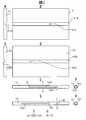
- FIG. 1A shows an information terminal 3 in a state where a movable housing (upper housing) 2 overlaps a fixed housing (lower housing) 1.
- FIG. 1B the information terminal 3 is used in a state where the movable casing 2 is slid with respect to the fixed casing 1.
- Examples of the information terminal 3 having such a configuration include a mobile phone, a mobile terminal (a small computer such as a tablet computer), or a game machine.
- an information terminal 4 having a structure in which the movable casing 2 is flat (full flat) with respect to the fixed casing 1 at the time of full sliding is disclosed in, for example, Patent Document 1 and Patent Document 2.
- Patent Document 1 there is a connection piece that connects the side surfaces of a fixed case (first case) and a movable case (second case), and one of two pins on the connection piece pivots on the movable case. The other is slidably engaged with the fixed housing.
- a fixed casing (second casing) and a movable casing (first casing) are connected by a link mechanism, and the movable casing is fully slid with respect to the fixed casing.
- the surface is designed to be fully flat.
- a small size such as a smartphone may be used, but a tablet with a large screen is suitable for viewing magazines and newspapers that have become electronic books. And since it is difficult to carry both smartphone-type mobile phones and tablets, there is a need to use them as tablets.
- the present application relates to a screen of a combined housing when the divided housings are combined in an electronic device such as an information terminal that combines a plurality of divided housings to form a single screen.
- An object of the present invention is to provide a coupling device for a multi-divided housing that is fully flat. It is another object of the present invention to provide an electronic device including a multi-divided housing coupling device that allows the screens of the joined housings to be fully flat when the separated housings are joined.
- the multi-divided housing coupling device is configured such that when the first to fourth housings are overlapped in this order, the first and second housings, the third housing, A rotating shaft that is arranged between the fourth housings and that slides the overlapping housings and then rotates one of them relative to the other by 180 degrees, and is parallel to the rotating shafts of the second and third housings.
- the electronic device including the multi-divided housing coupling device overlaps the first to fourth housings in this order
- the first and second Rotating shafts that are arranged between the housings and between the third and fourth housings, and after rotating the overlapping housings, rotate one of them 180 degrees with respect to the other
- a second hinge that joins the end surfaces on the hinge side and the opposite end surfaces to each other, and the second and third housings are slid with respect to the first and fourth housings by the rotation shaft to complete the slide.
- the second and third casings and the first and fourth casings are rotated around the rotation axis by the first and second hinges.
- An electronic device having a multi-divided housing coupling device that opens to form a flat surface, the display screen on the surface opposite to the surface on which the rotation shafts of the first to fourth housings are provided And one flat surface serves as one display screen.
- FIG. 1A is a perspective view showing a closed state of a slide-type information terminal according to related art
- FIG. 1B is a perspective view showing a state in which the information terminal shown in FIG. 1A is slid
- FIG. 1C is a further illustration of the information terminal shown in FIG.
- FIG. 1D is a perspective view showing a related art information terminal including a combined screen formed by combining four divided housings.
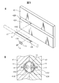
- FIG. FIG. 2A is a perspective view showing a state in which a screen is closed in an embodiment of an electronic device having a multi-divided housing
- FIG. It is an open perspective view showing a state in which one screen is formed on a flat surface.
- FIG. 3A illustrates a partial operation of the multi-divided housing coupling device according to the embodiment, in which FIG. 3A is a perspective view illustrating two housings that are overlapped and closed, and FIG. 3B is a diagram illustrating two housings illustrated in FIG.
- FIG. 3C is a perspective view showing a state in which the body slides using the rotating shaft of the coupling device, and FIG. 3C shows one of the two housings shown in FIG. 3B using the rotating shaft of the coupling device and 180 degrees with respect to the other.
- FIG. 3D is a perspective view showing a state in which the rotation of one casing shown in FIG. 3C is finished and the display surfaces of the two casings are flattened.
- FIG. 4A is a front view of the first casing
- FIG. 4A is a front view of the first casing
- FIG. 4B is a right side of the first casing shown in FIG. 4A.
- FIG. 4C is a front view of the second casing
- FIG. 4D is a left side view of the second casing shown in C
- FIG. 4E is a coupling built in between the first and second casings.
- 4F is a cross-sectional view taken along line FF in FIG. 4E
- FIG. 4G is a bottom view of the rotary shaft shown in FIG. 4E
- FIG. 4H is a cross-sectional view taken along line HH in FIG.
- FIG. 4I is a plan view of the sliding assist member inserted into the rotating shaft shown in FIGS. 4E and 4G
- FIG. 4J is a side view of the sliding assist member shown in FIG. 4I.
- FIG. 4I is a plan view of the sliding assist member inserted into the rotating shaft shown in FIGS. 4E and 4G
- FIG. 4J is a side view of the sliding assist member shown in FIG. 4I
- FIG. 5A is an assembly perspective view showing a state in which the rotating shaft shown in FIG. 4E is attached to the second housing using a sliding assist member
- FIG. 5B is a perspective view showing that the rotating shaft shown in FIG. 4E and FIG. It is sectional drawing which shows the state attached to the 1st and 2nd housing
- 2A shows a process in which the electronic device shown in FIG. 2A is transformed into the state shown in FIG. 2B.
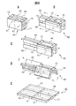
- FIG. 6A is a perspective view showing a state in which four housings are overlapped
- FIG. 6B shows the step shown in FIG.
- FIG. 6C is a perspective view showing a state in which the outer two casings of the four casings start to slide relative to the inner two casings, and FIG.
- FIG. 6C shows the outer side of the four casings shown in FIG. 6B.
- FIG. 6D is a perspective view showing a state where the two casings have finished sliding with respect to the two inner casings, and FIG. 6D shows two outer casings and two inner casings from the state shown in FIG.
- FIG. 6E is a perspective view showing a state in which rotation about the rotation axis of the hinge is started, and FIG. 6E shows that the outer two cases and the two inner cases are further rotated from the state shown in FIG. It is a perspective view which shows the state rotated.
- 2A is a front view of a process in which the electronic device shown in FIG. 2A is transformed into the state shown in FIG. 2B.
- FIG. 7A is a front view corresponding to FIGS.
- FIG. 7C is a front view showing a state in which the outer two housings and the inner two housings start to rotate around the rotation axis of the hinge, respectively, and FIG. 7C shows the two outer housings from the state shown in FIG. 7B.
- FIG. 7D is a front view showing a state in which the body and the inner two housings are further rotated, and FIG. 7D is a view showing the outer two housings and the two inner housings being further rotated from the state shown in FIG. It is a front view which shows the state rotated by each.
- FIG. 7D is a front view showing a state in which the outer two housings and the inner two housings start to rotate around the rotation axis of the hinge, respectively
- FIG. 7C shows the two outer housings from the state shown in FIG. 7B.
- FIG. 7D is a front view showing a state in which the body and the inner two housings are further rotated
- FIG. 7D is a view showing the outer two housings and the two inner housings
- FIG. 8A is a perspective view of an electronic device including eight housings formed by joining end surfaces on the side where the inner housing of the electronic device including four housings illustrated in FIG. 6A is not pulled out.
- FIG. 8B is a perspective view showing a state in which the outer two cases out of the four cases shown in FIG. 8A start to slide in opposite directions with respect to the inner two cases, corresponding to FIG. 6B.
- FIG. 8C is a perspective view showing a state in which the two outer casings of the four casings shown in FIG. 8B have finished sliding with respect to the inner two casings, and corresponds to FIG. 6C. It is a figure to do.
- FIG. 9A is a perspective view showing a state in which the outer two housings and the inner two housings have started to rotate around the rotation axis of the hinge from the state shown in FIG. 8C, and corresponds to FIG. 6D.
- FIG. 9B is a perspective view showing a state in which the outer two housings and the inner two housings are further rotated from the state shown in FIG. 9A and rotated 180 degrees each, corresponding to FIG. 6E. It is a figure to do.
- FIG. 11A shows the first and second casings to which the multi-divided casing coupling device having the slide assist mechanism shown in FIG.
- FIG. 11B is a side view showing a state in which the housing has been slid and rotated
- FIG. 11B is a side view showing a state in which the second housing is rotated 180 degrees around the rotation axis with respect to the first housing from the state of FIG.
- FIG. 12A is a side view showing the operation of the multi-divided housing coupling device provided with the slide assist mechanism when the second housing slides in the direction approaching the first housing from the state of FIG. 11B
- 12B is a side view illustrating the operation of the multi-divided housing coupling device having the slide assist mechanism when the second housing in FIG. 12A further slides with respect to the first housing and the two housings overlap each other.
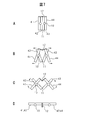
- FIG. 13A is an assembly perspective view showing the coupling of the spring and the piece member of the slide assist mechanism used in the coupling device of another embodiment
- FIG. 13B is the spring and the piece member of the slide assist mechanism used in the coupling device of another embodiment. It is a side view which shows the coupling
- FIG. 14A is a partial perspective view showing a hinge that joins the second housing and the third housing in the coupling device of another embodiment
- FIG. 14B shows the first housing and the first housing in the coupling device of another embodiment. It is a fragmentary perspective view which shows the hinge which couple
- FIG. 2A discloses a closed state of an embodiment of an electronic device 40 having a multi-part housing
- FIG. 2B shows the electronic device 40 in an opened state using a coupling device described below.
- the electronic device 40 of this embodiment includes first to fourth divided housings 41 to 44.
- the divided casings 41 to 44 are hereinafter simply referred to as casings 41 to 44.
- the first to fourth casings 41 to 44 have screens (displays) 41D to 44D, respectively.
- the displays 41D to 44D are close to each other and form one large screen. If any one of the first to fourth casings 41 to 44 is provided with a control device that displays an image of a quarter of one display image in synchronization with another screen, one A large image can be displayed on a large screen.
- the first to fourth casings 41 to 44 are a pair of the first and second casings 41 and 42, and the third and fourth casings 43 and 44 are It is a pair.
- the second casing 42 and the third casing 43 are disposed adjacent to each other, and one of the end faces in the longitudinal direction of the second casing 42 and the third casing 43 (the lower side in FIG. 2A).
- a first hinge 11 (hereinafter simply referred to as a hinge 11) for connecting the end faces is attached to the end face on the side.
- the second casing 42 and the third casing 43 can be opened in a V shape with the hinge 11 as a rotation axis.
- the first and fourth casings 41 and 44 arranged outside the electronic device 40 are connected to the other end surface in the longitudinal direction (the upper end surface in FIG. 2A) by connecting the end surfaces to each other.
- a hinge 12 (hereinafter simply referred to as hinge 12) is attached.
- the first casing 41 and the fourth casing 44 can be opened in a V shape with the hinge 12 as a rotation axis.
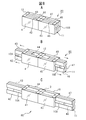
- FIG. 3A shows a state in which the first and second casings 41 and 42 are overlapped and closed.
- the rotating shaft 10 is accommodated in the overlapping surface of the first and second casings 41 and 42.
- the first and second casings 41 and 42 can be slid and rotated by the rotation shaft 10.
- FIG. 3B shows a state in which the second housing 42 slides in the direction P away from the first housing 41 shown in FIG. 3A using the rotating shaft 10.
- the length of the rotating shaft 10 protruding inward is the same.
- FIG. 3C shows a state in which the first housing 41 and the second housing 42 shown in FIG. 3B have slid to the maximum extent (sliding complete state, hereinafter also referred to as full sliding state). In the fully slid state, adjacent ends of the first casing 41 and the second casing 42 do not overlap with each other, and the second casing 42 is indicated by an arrow T around the rotation axis 10.
- the first housing 41 can be rotated 180 degrees.
- FIG. 3D shows a state in which the second housing 42 is rotated 180 degrees around the rotation axis 10 with respect to the first housing 41 from the state shown in FIG. 3C.
- the second housing 42 rotates 180 degrees around the rotation axis 10
- one surface of the housings of the first and second housings 41 and 42 becomes flat, and this surface is displayed on the display 41D. , 42D, two flat screens can be obtained.
- the side surface of the rotating shaft 10 is exposed on the back side of the flat two screens.
- the rotation shaft 10 does not have to be a perfect columnar shape, but may have a shape that allows the second housing 42 to rotate 180 degrees with respect to the first housing 41.
- FIG. 4A is a front view of the first casing 41
- FIG. 4B is a right side view of the first casing 41 shown in FIG. 4A.
- the first housing 41 is formed with a circumferential groove 41M at the longitudinal center. Further, there is a screw hole 41A for attaching a sliding auxiliary member described later at a predetermined position of the circumferential groove 41M.
- 4C is a front view of the second casing 42, and FIG.
- FIG. 4D is a left side view of the second casing 42 shown in FIG. 4C.
- the second housing 42 is formed with a circumferential groove 42M at the center in the longitudinal direction. Further, there is a screw hole 42A for attaching a sliding auxiliary member described later at a predetermined position of the circumferential groove 42M.
- FIG. 4E is a plan view of the rotary shaft 10 accommodated in the grooves 41M and 42M on the overlapping surfaces of the first and second casings 41 and 42
- FIG. 4F is a cross-sectional view taken along the line FF in FIG. 4E.
- 4G is a bottom view of the rotating shaft 10 shown in FIG. 4E
- FIG. 4H is a cross-sectional view taken along the line HH in FIG. 4G.
- the length of the rotating shaft 10 is the same as the length of the first and second casings 41 and 42 in the longitudinal direction.
- the rotating shaft 10 has a hollow tube shape, and as shown in FIG.
- slits 10S1 and 10S2 are provided in the longitudinal direction on the front side and the back side of the wall surface.
- a hole SH having a large diameter provided at one end of each of the slits 10S1 and 10S2 is for inserting a screw head or a screwdriver.
- An annular slit 10R extending in the circumferential direction is provided at the other end of the slit 10S2. As shown in FIG. 4H, the annular slit 10R has a length sufficient to move the screw that has moved the slit 10S2 to the opposite side by 180 degrees.
- FIG. 4I is a plan view of the sliding auxiliary member 13 inserted into the hollow rotary shaft 10 shown in FIGS. 4E to 4H
- FIG. 4J is a side view of the sliding auxiliary member 13 shown in FIG. 4I. is there.
- One surface in the longitudinal direction of the sliding auxiliary member 13 is a flat surface, and the other surface is a circumferential surface along the inner peripheral surface of the hollow rotating shaft 10.
- the sliding assisting member 13 is provided with a hole 13A penetrating from a flat surface to a circumferential surface for inserting a screw.
- One of the sliding assisting members 13 is attached to a screw hole 41A at a predetermined position of the circumferential groove 41M by a screw inserted through the slit 10S1 of the rotating shaft 10.
- the other one of the sliding assistance members 13 is attached to a screw hole 42A at a predetermined position of the circumferential groove 42M by a screw that passes through the slit 10S2 of the rotating shaft 10.
- FIG. 5A is an assembly perspective view showing a state in which the rotating shaft 10 shown in FIG. 4E is attached to the second casing 42 using the sliding assisting member 13.
- the sliding auxiliary member 13 is inserted into the hollow rotary shaft 10 in advance, and the screw 14 for attaching the sliding auxiliary member 13 to the second housing 42 is, for example, the end of the slit 10S1 shown in FIG. 4G. It is inserted into the rotary shaft 10 through the hole SH in the section. Further, the screw 14 attached to the sliding assisting member 13 is screwed to the second housing 42 by a driver inserted through the hole SH.
- the second casing 42 can move in the longitudinal direction with respect to the rotating shaft 10 and the rotating shaft 10 can be moved by the slit 10R. It can be rotated 180 degrees with respect to. Since the attachment of the other sliding assisting member 13 to the first casing 41 using the screw 14 can be performed in the same manner, the illustration is omitted.
- FIG. 5B is a cross-sectional view showing a state where the rotating shaft 10 shown in FIGS. 4E and 4F is attached to the first and second casings 41 and 42 by the sliding auxiliary member 13 and the screw 14.
- the first and second casings 41 and 42 have a boss portion to which the screw 14 is attached and other circuit parts, but these are not shown here, and the rotary shaft 10, the sliding auxiliary member 13, Only the positional relationship between the screw 14 and the first and second casings 41 and 42 is shown.
- the first casing 41 can only move in the longitudinal direction with respect to the rotation shaft 10, and the second casing 42 is long with respect to the rotation shaft 10.
- Directional movement and 180 degree rotation are possible.
- the lengths of the slits 10S1 and 10S2 and the positions of the screw holes 41A and 42A in the grooves 41M and 42M are determined by rotating the first and second casings 41 and 42 as shown in FIG. What is necessary is just to determine that 10 protrudes in the groove
- the first and second casings 41 and 42 have been described above, the third and fourth casings 43 and 44 have the same structure as the first and second casings 41 and 42 as described above. Therefore, the same operation as that of the first and second casings 41 and 42 is possible.
- FIG. 6A to FIG. 6E and FIG. 7A to FIG. 7C show a process in which the electronic device 40 including the first to fourth casings 41 to 44 shown in FIG. 2A is transformed into the state shown in FIG. 2B.
- the rotary shaft 10 is depicted as a simple columnar member, like the rotary shaft 10 shown in FIG. FIG. 6A shows a state in which the first to fourth casings 41 to 44 are overlapped.
- the longitudinal side surfaces of the second and third housings 42 and 43 are coupled by the hinge 11, and the longitudinal side surfaces of the first and fourth housings 41 and 44 are coupled by the hinge 12. ing.
- FIG. 6B shows that the first and fourth casings 41 and 44 on the outer side of the four casings 41 to 44 shown in FIG. 6A are connected to the second and third casings 42 and 43 on the inner side.
- the state which started to slide in the direction shown by the arrow is shown.
- the lengths of the rotary shafts 10 protruding toward the first and fourth casings 41 and 44 are the same.
- FIG. 6C shows a full slide state in which the outer first and fourth casings 41 and 44 shown in FIG. 6B have finished sliding with respect to the inner second and third casings 42 and 43. Yes.
- the end portions of the first and fourth casings 41 and 44 on the second and third casings 42 and 43 side, and the first and second casings 42 and 43 side by side. 4 does not overlap with the end portions of the casings 41 and 44 on the side.
- the length of the rotary shaft 10 protruding from the first and fourth housings 41 and 44 to the second and third housings 42 and 43 side, and the first from the second and third housings 42 and 43 to the first. And the length of the rotating shaft 10 which protrudes to the 4th housing
- casing 41 and 44 side is the same.
- FIGS. 7A to 7D are views of the state shown in FIGS. 6A to 6E viewed from the longitudinal direction of the electronic device 40.
- FIGS. 6A to 6C are all the same when viewed from the longitudinal direction of the electronic device 40, and this is shown in FIG. 7A.
- FIG. 7B shows a state where the first and fourth housings 41 and 44 and the second and third housings 42 and 43 are slightly expanded from the state shown in FIG. 6C.
- the first and fourth casings 41 and 44 and the second and third casings 42 and 43 are expanded, the first to fourth casings 41 to 44 all rotate around the rotation axis 10. I understand that.
- FIG. 7C shows a state in which the first and fourth casings 41 and 44 and the second and third casings 42 and 43 are further expanded from the state shown in FIG. 6D.
- FIG. 7D shows a view of the state shown in FIG. 6E viewed from the longitudinal direction of the electronic device 40. From FIG. 7D, it can be seen that the surfaces on which the displays of the first to fourth casings 41 to 44 after the rotation are completed are fully flat.
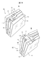
- FIG. 8A shows an electronic device 80 formed by using two of the electronic devices 40 and joining the end surfaces of the external housing on the side where the internal housing is not pulled out.
- the electronic device 80 includes first to eighth housings 41 to 48, and the first to fourth housings 41 to 44 have the same structure as the electronic device 40.
- the fifth to eighth casings 45 to 48 have a structure in which the first to fourth casings 41 to 44 rotate the electronic device 40 by 180 degrees in the longitudinal direction. That is, the fifth housing 45 has the same structure as the fourth housing 44, the sixth housing 46 has the same structure as the third housing 43, and the seventh housing 47 has the same structure as the second housing 42.
- the same structure and the eighth casing 48 have the same structure as the first casing 41.
- the end surface on the 48 side and the end surface on the fourth housing 44 side of the eighth housing 48 are joined.
- FIG. 8B shows that the second and third casings 42 and 43 are pulled out to one side with respect to the first and fourth casings 41 and 44, respectively.
- the sixth and seventh housings 46 and 47 are pulled out to the other with respect to the fifth and eighth housings 45 and 48.
- 8C shows that the second and third housings 42 and 43 are fully slid with respect to the first and fourth housings 41 and 44, and the sixth and fourth housings 45 and 48 are sixth and sixth. A state in which the seventh casings 46 and 47 are fully slid is shown.
- FIG. 8C shows an electronic device 80 corresponding to the electronic device 40 shown in FIG. 6C.
- 9A shows the second and third housings 42 and 43, the first and fourth housings 41 and 44, the fifth and eighth housings 45 and 48, and the sixth housing from the state shown in FIG. 8C. And the seventh casings 46 and 47 are rotated around the rotation axes of the corresponding hinges 11 and 12, respectively. Since the end portions of the first housing and the fifth housings 41 and 45 and the fourth housing and the eighth housings 44 and 48 are joined, they move together.
- 9B shows the second and third housings 42 and 43, the first and fourth housings 41 and 44, the fifth and eighth housings 45 and 48, and the sixth and sixth housings from the state shown in FIG. 9A. 7 shows a state in which the casings 46 and 47 of the seven are rotated 180 degrees.
- the second and third casings 42 and 43, the first and fourth casings 41 and 44, the fifth and eighth casings 45 and 48, and the sixth and seventh casings 46 and 47 are 180 respectively. When it is rotated, a full flat screen of 8 screens is completed.
- the disclosed electronic devices 40 and 80 can form a flat large screen by expanding a plurality of stacked casings with a coupling device, so that the size is small when carrying and a large screen is displayed when displaying an image. Can be realized. Further, in the embodiment shown in FIGS. 8A to 8C and FIGS. 9A and 9B, since two electronic devices 40 are joined as they are, the display screen shown in FIG. 9B is horizontally long. If the aspect ratio is changed, a screen with an aspect ratio of 4: 3 or 16: 9 can be realized.
- FIG. 10 is an assembled perspective view showing a partial structure of a multi-divided housing coupling device provided with the slide assist mechanism 30.
- FIG. 10 shows first and second housings 41 and 42 in the electronic device 40. As shown in FIG. Shown is a slide assist mechanism 30 that is attached to the.
- the first and second casings 41 and 42 are shown in an open state, which corresponds to the state of FIG. 3D of the above-described embodiment viewed from the back side.
- the rotating shaft 10C shown in FIG. 10 corresponds to the rotating shaft 10 shown in FIG. 3C, for example.
- On the overlapping surface side of the first housing 41 there is a groove 41N having the same width and the same depth and extending in the longitudinal direction.
- a rectangular mounting recess 41T for mounting a mounting plate 41P described later is provided in the middle of the groove 41N.
- the second casing 42 has the same depth but is continuously provided with a wide groove 42W and a narrow groove 42N.
- the depth of the wide groove 42 ⁇ / b> W is the same as the groove 41 ⁇ / b> N in the first housing 41.
- One wall surface of the wide groove 42 ⁇ / b> W is continuous with one wall surface of the groove 41 ⁇ / b> N in the first housing 41.
- the narrow groove 42 is provided so as to overlap the groove 41N when the second casing 42 is rotated by 180 degrees around the rotation axis 10C and superimposed on the first casing 41.
- the rectangular attachment recessed part 42T for attaching two brackets 42B is provided in two places.
- the slide assist mechanism 30 includes a main body 33, an annular part 35, a mounting plate 41P, two brackets 42B, and a rotating shaft 10C.
- the main body 33 has a rectangular plate shape, the length of the main body 33 is the same as the lengths of the first and second casings 41 and 42, and the width of the main body 33 is a groove in the first casing 41. It is a width that can slide within 41N.
- the length of the rotating shaft 10 ⁇ / b> C is the same as the length of the main body 33.
- the thickness of the main body 33 is such that when the first and second casings 41 and 42 overlap each other, the thickness can slide in the space formed by the grooves 41N and 42N, that is, the depth of the groove 41N. It is about twice as thick. In practice, there is a cover on the surface of the main body 33 facing the grooves 41N and 42N, but this cover is not shown.
- the main body 33 includes an oval concave portion 36 and a cutout portion 37 that is a space that is communicated with the concave portion 36 and cut out to one long side portion of the main body 33.
- a guide member 34 is provided in the recess 36, and both end portions of the guide member 34 are semicircular, and a semicircular passage is formed between both ends of the recess 36.
- a slit 36S having stepped portions 36D at both ends is formed on the opposite side of the notched portion 37 of the guide member 34, and a piece member described later is accommodated in a portion adjacent to the stepped portion 36D of the slit 36S. There are locking recesses 51 and 52 to stop.
- the annular part 35 is a belt-like member, and the first slide member 31 is attached to the inner peripheral surface thereof, and the second slide member 32 is attached to the outer peripheral surface thereof.
- the lengths of the first and second slide members 31 and 32 are the same. Further, the length of the annular part 35 from one end of the first slide member 31 to one end of the second slide member 32 and the second slide from the other end of the first slide member 31. The length of the annular part 35 to the other end of the member 32 is also the same.
- the annular part 35 is incorporated in the recess 36 of the main body 33 with both ends inserted into the semicircular passage described above, and the first slide member 31 can move in the slit 36S of the guide member 34. Further, the second slide member 32 can move in the cutout portion 37 in a state where the annular part 35 is incorporated in the recess 36.
- a mounting plate 41P is attached to the first housing 41 side of the first slide member 31 with screws 15, and the mounting plate 41P to which the first slide member 31 is attached is attached to the first housing 41 with screws 15. Is fixed to the mounting recess 41T. Since the recess 32A is provided in the second slide member 32, the rotary shaft 10C is inserted through the shaft insertion hole 38 provided in the main body 33 with the two brackets 42B positioned in the recess 32A. The rotary shaft 10C is passed through the hole 42H provided in the bracket 42B. The rotary shaft 10C passing through the hole 42H provided in the bracket 42B passes through the notch 37 and then passes through the shaft insertion hole 38 provided on the opposite side of the main body 33. When the bracket 42B inserted through the rotary shaft 10C is positioned at both ends of the recess 32A, the bracket 42B can be fixed to the mounting recess 42T provided in the second housing 42 with the screw 15.
- the annular part 35 is a belt-like member in this embodiment, but may be a linear member using a wire or the like.
- the annular component 35 can be integrally formed by cutting out the first and second slide members 31 and 32 from a synthetic resin plate. Also, the first and second slide members 31 and 32 and the annular part 35 are prepared separately, and the annular part 35 is connected to the first and second slide members 31 and 32. Can be made.
- one end of the first slide member 31 is slit. It is located within the stepped portion 36D on the first housing 41 side of 36S.
- the assist spring member 18 including the tension spring 19 and the piece member 20 is attached in the slit 36S.
- one of the piece members 20 is inserted into the locking recess 51, the tension spring 19 is inserted into the slit 36S between the first slide member 31 and the guide member 34, and the other of the piece members 20 is the first one.
- the end of the slide member 31 is locked. This state is the state shown in FIG. 11A.
- the assist spring member 18 includes a tension spring 19 that is an elastic body, and a piece member 20 that is swingably attached to both ends of the tension spring 19.
- the diameter of the piece member 20 is larger than the width of the tension spring 19 in the short direction.
- the piece member 20 forms a notch 21 by cutting a part of a disk-shaped main body 23 into an arc shape, and a post 22 near the outer periphery of the main body 23 of the notch 21. Is a projecting project.
- the hook portion 19H of the tension spring 19 is attached to the post 22.
- FIG. 13B shows the tension spring 19 shown in FIG. 13A and the piece members 20 attached to both ends thereof.
- the piece member 20 can swing with respect to the tension spring 19.
- the piece member 20 has a hook portion (post 22) capable of locking the hook portion 19H of the spring 19 in part.
- the piece member 20 may have a circular shape or the like so that the piece member 20 can be rolled when the part that locks the piece member 20 is replaced as will be described later.
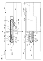
- FIG. 11A in a state where the slide assist mechanism 30 is attached to the first and second casings 41 and 42, the second casing 42 has a rotational axis 10C relative to the first casing 41. And the bracket 42B can be rotated 180 degrees.
- FIG. 11B shows a state in which the second housing 42 is rotated 180 degrees with respect to the first housing 41 by the rotating shaft 10C and the bracket 42B.
- the state shown in FIG. 11B corresponds to the state shown in FIG. 3C in the above-described embodiment.
- the groove 41N of the first housing 41 and the groove 42N of the second housing 42 are connected in a straight line.
- the slide assist mechanism 30 causes the grooves 41N of the first housing 41 and the grooves of the second housing 42 to be applied. Since 42N is slid, the 1st housing
- FIG. 11B in the state where an external force is started to be applied to both ends of the first housing 41 and the second housing 42, one piece member 20 of the assist spring member 18 is locked to the locking recess 51. The other piece member 20 is locked to one end of the first slide member 31. Accordingly, the tension spring 19 extends due to the movement of the first casing 41 in the direction approaching the second casing 42. When the first casing 41 further approaches the second casing 42, the other end of the first slide member 31 passes through the position of the locking recess 51.
- FIG. 12A shows a state in which the first casing 41 and the second casing 42 are close to the half of the total length from the state of FIG. 11B, and corresponds to the state of FIG. 3B of the above-described embodiment. .
- the second housing 42 is not shown, and only its position is indicated by a two-dot chain line.
- the first casing 41 and the second casing 42 approach each other while the piece members 20 at both ends are locked to both ends of the first slide member 31.
- the tension spring 19 is extended, and the piece member 20 is applied with a pulling force in a direction approaching the other piece member 20.
- FIG. 12B shows a state in which the first and second casings 41 and 42 overlap each other, and corresponds to the state shown in FIG. 3A of the above-described embodiment.
- the slide assist mechanism 30 performs the operation from the state shown in FIG. 12A to the state shown in FIG. 11B. .
- an assist force in the direction of moving the first and second casings 41 and 42 away is generated by the tension spring 19, and The force when the second casings 41 and 42 are in the full slide state is reduced.
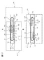
- FIG. 14A shows the hinge 11 that couples the second housing 42 and the third housing 43 in the electronic device 40 including the coupling device of another embodiment.
- One end of the hinge 11 is fixed to the end of the second casing 42 by a screw 16, and the other end of the hinge 11 is fixed to the end of the third casing by a screw 16.
- the second casing 42 and the third casing 43 can rotate around the rotation axis 11 ⁇ / b> A of the hinge 11.
- FIG. 14B shows the hinge 12 that couples the first housing 41 and the fourth housing 44 in the electronic device 40 including the coupling device of another embodiment.
- One end of the hinge 12 is fixed to the end of the first housing 41 by a screw 16, and the other end of the hinge 12 is fixed to the end of the fourth housing by a screw 16.
- the first casing 41 and the fourth casing 44 can rotate around the rotation axis 12 ⁇ / b> A of the hinge 12.
- the electronic devices 40 and 80 having the multi-divided housing coupling device of the present application can form a full flat large screen in a state where a plurality of housings having screens are coupled, and rotate. By sliding each case in a sliding motion, it is possible to make it convenient for carrying.
Landscapes
- Engineering & Computer Science (AREA)
- Theoretical Computer Science (AREA)
- Physics & Mathematics (AREA)
- Computer Hardware Design (AREA)
- Human Computer Interaction (AREA)
- General Engineering & Computer Science (AREA)
- General Physics & Mathematics (AREA)
- Mathematical Physics (AREA)
- Signal Processing (AREA)
- Multimedia (AREA)
- Microelectronics & Electronic Packaging (AREA)
- Mechanical Engineering (AREA)
- Telephone Set Structure (AREA)
Priority Applications (1)
| Application Number | Priority Date | Filing Date | Title |
|---|---|---|---|
| US14/315,534 US9030812B2 (en) | 2011-12-28 | 2014-06-26 | Joining structure of multi-segment housing and electronic device provided with that joining structure |
Applications Claiming Priority (2)
| Application Number | Priority Date | Filing Date | Title |
|---|---|---|---|
| JP2011-289410 | 2011-12-28 | ||
| JP2011289410A JP5783039B2 (ja) | 2011-12-28 | 2011-12-28 | 多分割筐体の結合装置及び該結合装置を備えた電子装置 |
Related Child Applications (1)
| Application Number | Title | Priority Date | Filing Date |
|---|---|---|---|
| US14/315,534 Continuation US9030812B2 (en) | 2011-12-28 | 2014-06-26 | Joining structure of multi-segment housing and electronic device provided with that joining structure |
Publications (1)
| Publication Number | Publication Date |
|---|---|
| WO2013100103A1 true WO2013100103A1 (ja) | 2013-07-04 |
Family
ID=48697581
Family Applications (1)
| Application Number | Title | Priority Date | Filing Date |
|---|---|---|---|
| PCT/JP2012/083989 Ceased WO2013100103A1 (ja) | 2011-12-28 | 2012-12-27 | 多分割筐体の結合装置及び該結合装置を備えた電子装置 |
Country Status (3)
| Country | Link |
|---|---|
| US (1) | US9030812B2 (enExample) |
| JP (1) | JP5783039B2 (enExample) |
| WO (1) | WO2013100103A1 (enExample) |
Cited By (1)
| Publication number | Priority date | Publication date | Assignee | Title |
|---|---|---|---|---|
| CN110138918A (zh) * | 2018-02-09 | 2019-08-16 | 广东欧珀移动通信有限公司 | 移动终端 |
Families Citing this family (19)
| Publication number | Priority date | Publication date | Assignee | Title |
|---|---|---|---|---|
| CN105164599A (zh) * | 2013-04-30 | 2015-12-16 | 富士通株式会社 | 具备分割筐体的结合装置以及分割筐体的电子装置 |
| CN105164602A (zh) * | 2013-04-30 | 2015-12-16 | 富士通株式会社 | 多分割框体的结合装置以及具备该结合装置的电子装置 |
| US20150335158A1 (en) * | 2014-05-23 | 2015-11-26 | Midlake Products & Manufacturing Company | Monitor bracket assembly |
| JP6425114B2 (ja) | 2014-07-02 | 2018-11-21 | Tianma Japan株式会社 | 折り畳み式表示装置及び電気機器 |
| JP6570268B2 (ja) * | 2015-03-06 | 2019-09-04 | キヤノン株式会社 | 表示装置 |
| JP2016194606A (ja) * | 2015-03-31 | 2016-11-17 | キヤノン株式会社 | 表示装置 |
| US20180070843A1 (en) * | 2016-09-12 | 2018-03-15 | Reflexion Interactive Technologies Llc | Portable rapid neurological and motor function screening apparatus |
| USD784952S1 (en) * | 2016-10-19 | 2017-04-25 | Nanolumens Acquisition, Inc. | Linear shaped digital display |
| USD791235S1 (en) | 2016-12-21 | 2017-07-04 | Nanolumens Acquisition, Inc. | Digital display |
| USD801300S1 (en) | 2017-04-06 | 2017-10-31 | Nanolumens Acquisition, Inc. | Linear shaped digital display |
| USD826936S1 (en) | 2017-06-23 | 2018-08-28 | Nanolumens Acquisition, Inc. | Five sided light emitting display |
| USD806670S1 (en) | 2017-10-05 | 2018-01-02 | Nanolumens Acquisition, Inc. | Linear shaped digital display |
| USD831120S1 (en) | 2017-11-29 | 2018-10-16 | Nanolumens Acquisition, Inc. | Rhomboidal shaped light emitting digital display |
| USD891426S1 (en) * | 2018-05-11 | 2020-07-28 | Fuvi Cognitive Network Corp. | Mobile device for visual and cognitive communication assistance |
| USD928231S1 (en) | 2018-06-29 | 2021-08-17 | Nanolumens Acquisition, Inc. | Wave shaped two-sided light emitting digital display |
| USD916969S1 (en) | 2018-07-09 | 2021-04-20 | Nanolumens Acquisition, Inc. | Ring shaped two-sided light emitting digital display |
| USD1010649S1 (en) | 2019-07-22 | 2024-01-09 | Nanolumens Acquisition, Inc. | Light emitting digital display panel |
| EP4180907A4 (en) * | 2020-12-02 | 2024-03-27 | Samsung Electronics Co., Ltd. | FOLDABLE ELECTRONIC DEVICE |
| CN219346007U (zh) * | 2023-02-22 | 2023-07-14 | 深圳华一精品科技有限公司 | 一种便携式显示器 |
Citations (4)
| Publication number | Priority date | Publication date | Assignee | Title |
|---|---|---|---|---|
| JPH0444154A (ja) * | 1990-06-11 | 1992-02-13 | Toshiba Corp | 折畳み型電子装置 |
| JP2009071588A (ja) * | 2007-09-13 | 2009-04-02 | Kyocera Corp | 携帯通信端末機 |
| JP2010154149A (ja) * | 2008-12-25 | 2010-07-08 | Kyocera Corp | 開閉式小型電子機器 |
| JP2010266752A (ja) * | 2009-05-15 | 2010-11-25 | Ricoh Co Ltd | ディスプレイ装置 |
Family Cites Families (14)
| Publication number | Priority date | Publication date | Assignee | Title |
|---|---|---|---|---|
| KR100284342B1 (ko) * | 1998-05-30 | 2001-03-02 | 김순택 | 플렉시블한액정표시소자를구비한휴대용액정표시장치 |
| FI111998B (fi) * | 1999-12-08 | 2003-10-15 | Nokia Corp | Käyttöliittymä |
| US6643124B1 (en) * | 2000-08-09 | 2003-11-04 | Peter J. Wilk | Multiple display portable computing devices |
| US6577496B1 (en) * | 2001-01-18 | 2003-06-10 | Palm, Inc. | Non-rigid mounting of a foldable display |
| US7187363B2 (en) * | 2001-11-30 | 2007-03-06 | Palm, Inc. | Integrated handheld data processing device having a sliding form factor |
| US7095387B2 (en) * | 2002-02-28 | 2006-08-22 | Palm, Inc. | Display expansion method and apparatus |
| EP1642253B1 (en) * | 2003-06-23 | 2012-10-03 | Simon Richard Daniel | Display device having an extendible screen |
| US7667962B2 (en) * | 2004-08-20 | 2010-02-23 | Mullen Jeffrey D | Wireless devices with flexible monitors and keyboards |
| US7782274B2 (en) * | 2006-06-09 | 2010-08-24 | Cfph, Llc | Folding multimedia display device |
| US20090009423A1 (en) * | 2007-07-07 | 2009-01-08 | Yuming Huang | Variable size electronic display based on slide-out and slide-in mechanism |
| US8863038B2 (en) * | 2008-09-08 | 2014-10-14 | Qualcomm Incorporated | Multi-panel electronic device |
| KR20100038008A (ko) * | 2008-10-02 | 2010-04-12 | 삼성전자주식회사 | 3차원 다중변형 디바이스 |
| KR101067587B1 (ko) * | 2010-01-29 | 2011-09-27 | 주식회사 팬택 | 형태 변환 특성이 있는 플렉서블 단말기, 그 형태 변환 방법 및 형태 변환장치 |
| US8605421B2 (en) * | 2011-08-17 | 2013-12-10 | Creator Technology B.V. | Display device with flexible display |
-
2011
- 2011-12-28 JP JP2011289410A patent/JP5783039B2/ja not_active Expired - Fee Related
-
2012
- 2012-12-27 WO PCT/JP2012/083989 patent/WO2013100103A1/ja not_active Ceased
-
2014
- 2014-06-26 US US14/315,534 patent/US9030812B2/en not_active Expired - Fee Related
Patent Citations (4)
| Publication number | Priority date | Publication date | Assignee | Title |
|---|---|---|---|---|
| JPH0444154A (ja) * | 1990-06-11 | 1992-02-13 | Toshiba Corp | 折畳み型電子装置 |
| JP2009071588A (ja) * | 2007-09-13 | 2009-04-02 | Kyocera Corp | 携帯通信端末機 |
| JP2010154149A (ja) * | 2008-12-25 | 2010-07-08 | Kyocera Corp | 開閉式小型電子機器 |
| JP2010266752A (ja) * | 2009-05-15 | 2010-11-25 | Ricoh Co Ltd | ディスプレイ装置 |
Cited By (2)
| Publication number | Priority date | Publication date | Assignee | Title |
|---|---|---|---|---|
| CN110138918A (zh) * | 2018-02-09 | 2019-08-16 | 广东欧珀移动通信有限公司 | 移动终端 |
| CN110138918B (zh) * | 2018-02-09 | 2024-04-19 | Oppo广东移动通信有限公司 | 移动终端 |
Also Published As
| Publication number | Publication date |
|---|---|
| JP5783039B2 (ja) | 2015-09-24 |
| US20140306864A1 (en) | 2014-10-16 |
| US9030812B2 (en) | 2015-05-12 |
| JP2013138393A (ja) | 2013-07-11 |
Similar Documents
| Publication | Publication Date | Title |
|---|---|---|
| JP5783039B2 (ja) | 多分割筐体の結合装置及び該結合装置を備えた電子装置 | |
| JP5979313B2 (ja) | 多分割筐体の結合装置及び該結合装置を備えた電子装置 | |
| CN114779889A (zh) | 铰接模块和包括铰接模块的可折叠电子设备 | |
| CN112947692B (zh) | 铰链组件及电子设备 | |
| CN109313469A (zh) | 铰接设备 | |
| WO2023071130A1 (zh) | 铰链装置及折叠式电子设备 | |
| US9750144B2 (en) | Connecting system of multi-section housing and electronic device provided with that connecting system | |
| WO2022262457A1 (zh) | 铰链组件及可折叠的电子设备 | |
| CN113027901A (zh) | Z轴铰链装置及使用此z轴铰链装置的电子机器 | |
| US9826647B2 (en) | Connecting system of multi-section housing and electronic device provided with that connecting system | |
| WO2024146310A1 (zh) | 一种转轴机构和电子设备 | |
| WO2013031386A1 (ja) | 携帯端末装置 | |
| CN116136230A (zh) | 支撑组件、可折叠显示屏和终端设备 | |
| CN111491043B (zh) | 外柔性屏移动终端的铰链、铰链装置及柔性屏移动终端 | |
| CN117135246A (zh) | 折叠装置以及电子设备 | |
| WO2024109284A1 (zh) | 转轴装置、折叠壳体及电子设备 | |
| CN116608201B (zh) | 转轴装置、折叠壳体及电子设备 | |
| JP5752995B2 (ja) | 折り畳み式電子機器 | |
| WO2023231390A1 (zh) | 转轴装置、折叠壳体及电子设备 | |
| CN120335553A (zh) | 电子设备 | |
| TWM539213U (zh) | 軸心轉動位移樞軸器 | |
| CN120292166A (zh) | 折叠机构、同步组件、折叠装置以及电子设备 | |
| CN119712701A (zh) | 联动机构、折叠壳体及电子设备 | |
| CN118869849A (zh) | 折叠装置、壳体组件和电子设备 | |
| CN120292167A (zh) | 折叠装置、折叠壳体及电子设备 |
Legal Events
| Date | Code | Title | Description |
|---|---|---|---|
| 121 | Ep: the epo has been informed by wipo that ep was designated in this application |
Ref document number: 12861738 Country of ref document: EP Kind code of ref document: A1 |
|
| NENP | Non-entry into the national phase |
Ref country code: DE |
|
| 122 | Ep: pct application non-entry in european phase |
Ref document number: 12861738 Country of ref document: EP Kind code of ref document: A1 |