WO2013100103A1 - 多分割筐体の結合装置及び該結合装置を備えた電子装置 - Google Patents
多分割筐体の結合装置及び該結合装置を備えた電子装置 Download PDFInfo
- Publication number
- WO2013100103A1 WO2013100103A1 PCT/JP2012/083989 JP2012083989W WO2013100103A1 WO 2013100103 A1 WO2013100103 A1 WO 2013100103A1 JP 2012083989 W JP2012083989 W JP 2012083989W WO 2013100103 A1 WO2013100103 A1 WO 2013100103A1
- Authority
- WO
- WIPO (PCT)
- Prior art keywords
- housings
- casings
- coupling device
- slide member
- rotating shaft
- Prior art date
Links
- 230000008878 coupling Effects 0.000 claims description 54
- 238000010168 coupling process Methods 0.000 claims description 54
- 238000005859 coupling reaction Methods 0.000 claims description 54
- 230000002093 peripheral effect Effects 0.000 claims description 7
- 230000033001 locomotion Effects 0.000 claims description 4
- 238000000034 method Methods 0.000 description 3
- 238000013459 approach Methods 0.000 description 2
- 238000003780 insertion Methods 0.000 description 2
- 230000037431 insertion Effects 0.000 description 2
- 238000010586 diagram Methods 0.000 description 1
- 230000026058 directional locomotion Effects 0.000 description 1
- 230000000149 penetrating effect Effects 0.000 description 1
- 229920003002 synthetic resin Polymers 0.000 description 1
- 239000000057 synthetic resin Substances 0.000 description 1
Images


Classifications
-
- H—ELECTRICITY
- H05—ELECTRIC TECHNIQUES NOT OTHERWISE PROVIDED FOR
- H05K—PRINTED CIRCUITS; CASINGS OR CONSTRUCTIONAL DETAILS OF ELECTRIC APPARATUS; MANUFACTURE OF ASSEMBLAGES OF ELECTRICAL COMPONENTS
- H05K7/00—Constructional details common to different types of electric apparatus
- H05K7/14—Mounting supporting structure in casing or on frame or rack
- H05K7/16—Mounting supporting structure in casing or on frame or rack on hinges or pivots
-
- G—PHYSICS
- G06—COMPUTING; CALCULATING OR COUNTING
- G06F—ELECTRIC DIGITAL DATA PROCESSING
- G06F1/00—Details not covered by groups G06F3/00 - G06F13/00 and G06F21/00
- G06F1/16—Constructional details or arrangements
- G06F1/1613—Constructional details or arrangements for portable computers
- G06F1/1615—Constructional details or arrangements for portable computers with several enclosures having relative motions, each enclosure supporting at least one I/O or computing function
- G06F1/1624—Constructional details or arrangements for portable computers with several enclosures having relative motions, each enclosure supporting at least one I/O or computing function with sliding enclosures, e.g. sliding keyboard or display
-
- E—FIXED CONSTRUCTIONS
- E05—LOCKS; KEYS; WINDOW OR DOOR FITTINGS; SAFES
- E05D—HINGES OR SUSPENSION DEVICES FOR DOORS, WINDOWS OR WINGS
- E05D3/00—Hinges with pins
- E05D3/06—Hinges with pins with two or more pins
- E05D3/12—Hinges with pins with two or more pins with two parallel pins and one arm
-
- G—PHYSICS
- G06—COMPUTING; CALCULATING OR COUNTING
- G06F—ELECTRIC DIGITAL DATA PROCESSING
- G06F1/00—Details not covered by groups G06F3/00 - G06F13/00 and G06F21/00
- G06F1/16—Constructional details or arrangements
- G06F1/1613—Constructional details or arrangements for portable computers
- G06F1/1615—Constructional details or arrangements for portable computers with several enclosures having relative motions, each enclosure supporting at least one I/O or computing function
- G06F1/1616—Constructional details or arrangements for portable computers with several enclosures having relative motions, each enclosure supporting at least one I/O or computing function with folding flat displays, e.g. laptop computers or notebooks having a clamshell configuration, with body parts pivoting to an open position around an axis parallel to the plane they define in closed position
-
- G—PHYSICS
- G06—COMPUTING; CALCULATING OR COUNTING
- G06F—ELECTRIC DIGITAL DATA PROCESSING
- G06F1/00—Details not covered by groups G06F3/00 - G06F13/00 and G06F21/00
- G06F1/16—Constructional details or arrangements
- G06F1/1613—Constructional details or arrangements for portable computers
- G06F1/1633—Constructional details or arrangements of portable computers not specific to the type of enclosures covered by groups G06F1/1615 - G06F1/1626
- G06F1/1637—Details related to the display arrangement, including those related to the mounting of the display in the housing
- G06F1/1641—Details related to the display arrangement, including those related to the mounting of the display in the housing the display being formed by a plurality of foldable display components
-
- G—PHYSICS
- G06—COMPUTING; CALCULATING OR COUNTING
- G06F—ELECTRIC DIGITAL DATA PROCESSING
- G06F3/00—Input arrangements for transferring data to be processed into a form capable of being handled by the computer; Output arrangements for transferring data from processing unit to output unit, e.g. interface arrangements
- G06F3/14—Digital output to display device ; Cooperation and interconnection of the display device with other functional units
- G06F3/1423—Digital output to display device ; Cooperation and interconnection of the display device with other functional units controlling a plurality of local displays, e.g. CRT and flat panel display
- G06F3/1446—Digital output to display device ; Cooperation and interconnection of the display device with other functional units controlling a plurality of local displays, e.g. CRT and flat panel display display composed of modules, e.g. video walls
-
- H—ELECTRICITY
- H04—ELECTRIC COMMUNICATION TECHNIQUE
- H04M—TELEPHONIC COMMUNICATION
- H04M1/00—Substation equipment, e.g. for use by subscribers
- H04M1/02—Constructional features of telephone sets
- H04M1/0202—Portable telephone sets, e.g. cordless phones, mobile phones or bar type handsets
- H04M1/0206—Portable telephones comprising a plurality of mechanically joined movable body parts, e.g. hinged housings
- H04M1/0208—Portable telephones comprising a plurality of mechanically joined movable body parts, e.g. hinged housings characterized by the relative motions of the body parts
- H04M1/0235—Slidable or telescopic telephones, i.e. with a relative translation movement of the body parts; Telephones using a combination of translation and other relative motions of the body parts
- H04M1/0237—Sliding mechanism with one degree of freedom
-
- E—FIXED CONSTRUCTIONS
- E05—LOCKS; KEYS; WINDOW OR DOOR FITTINGS; SAFES
- E05D—HINGES OR SUSPENSION DEVICES FOR DOORS, WINDOWS OR WINGS
- E05D15/00—Suspension arrangements for wings
- E05D15/56—Suspension arrangements for wings with successive different movements
- E05D15/58—Suspension arrangements for wings with successive different movements with both swinging and sliding movements
- E05D15/581—Suspension arrangements for wings with successive different movements with both swinging and sliding movements the swinging axis laying in the sliding direction
-
- E05Y2999/00—
-
- H—ELECTRICITY
- H04—ELECTRIC COMMUNICATION TECHNIQUE
- H04M—TELEPHONIC COMMUNICATION
- H04M1/00—Substation equipment, e.g. for use by subscribers
- H04M1/02—Constructional features of telephone sets
- H04M1/0202—Portable telephone sets, e.g. cordless phones, mobile phones or bar type handsets
- H04M1/0206—Portable telephones comprising a plurality of mechanically joined movable body parts, e.g. hinged housings
- H04M1/0208—Portable telephones comprising a plurality of mechanically joined movable body parts, e.g. hinged housings characterized by the relative motions of the body parts
- H04M1/0214—Foldable telephones, i.e. with body parts pivoting to an open position around an axis parallel to the plane they define in closed position
- H04M1/0216—Foldable in one direction, i.e. using a one degree of freedom hinge
-
- H—ELECTRICITY
- H04—ELECTRIC COMMUNICATION TECHNIQUE
- H04M—TELEPHONIC COMMUNICATION
- H04M1/00—Substation equipment, e.g. for use by subscribers
- H04M1/02—Constructional features of telephone sets
- H04M1/0202—Portable telephone sets, e.g. cordless phones, mobile phones or bar type handsets
- H04M1/0206—Portable telephones comprising a plurality of mechanically joined movable body parts, e.g. hinged housings
- H04M1/0247—Portable telephones comprising a plurality of mechanically joined movable body parts, e.g. hinged housings comprising more than two body parts
Definitions
- the present application relates to a multi-divided housing coupling device and an electronic device including the coupling device.
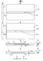
- FIG. 1A shows an information terminal 3 in a state where a movable housing (upper housing) 2 overlaps a fixed housing (lower housing) 1.
- FIG. 1B the information terminal 3 is used in a state where the movable casing 2 is slid with respect to the fixed casing 1.
- Examples of the information terminal 3 having such a configuration include a mobile phone, a mobile terminal (a small computer such as a tablet computer), or a game machine.
- an information terminal 4 having a structure in which the movable casing 2 is flat (full flat) with respect to the fixed casing 1 at the time of full sliding is disclosed in, for example, Patent Document 1 and Patent Document 2.
- Patent Document 1 there is a connection piece that connects the side surfaces of a fixed case (first case) and a movable case (second case), and one of two pins on the connection piece pivots on the movable case. The other is slidably engaged with the fixed housing.
- a fixed casing (second casing) and a movable casing (first casing) are connected by a link mechanism, and the movable casing is fully slid with respect to the fixed casing.
- the surface is designed to be fully flat.
- a small size such as a smartphone may be used, but a tablet with a large screen is suitable for viewing magazines and newspapers that have become electronic books. And since it is difficult to carry both smartphone-type mobile phones and tablets, there is a need to use them as tablets.
- the present application relates to a screen of a combined housing when the divided housings are combined in an electronic device such as an information terminal that combines a plurality of divided housings to form a single screen.
- An object of the present invention is to provide a coupling device for a multi-divided housing that is fully flat. It is another object of the present invention to provide an electronic device including a multi-divided housing coupling device that allows the screens of the joined housings to be fully flat when the separated housings are joined.
- the multi-divided housing coupling device is configured such that when the first to fourth housings are overlapped in this order, the first and second housings, the third housing, A rotating shaft that is arranged between the fourth housings and that slides the overlapping housings and then rotates one of them relative to the other by 180 degrees, and is parallel to the rotating shafts of the second and third housings.
- the electronic device including the multi-divided housing coupling device overlaps the first to fourth housings in this order
- the first and second Rotating shafts that are arranged between the housings and between the third and fourth housings, and after rotating the overlapping housings, rotate one of them 180 degrees with respect to the other
- a second hinge that joins the end surfaces on the hinge side and the opposite end surfaces to each other, and the second and third housings are slid with respect to the first and fourth housings by the rotation shaft to complete the slide.
- the second and third casings and the first and fourth casings are rotated around the rotation axis by the first and second hinges.
- An electronic device having a multi-divided housing coupling device that opens to form a flat surface, the display screen on the surface opposite to the surface on which the rotation shafts of the first to fourth housings are provided And one flat surface serves as one display screen.
- FIG. 1A is a perspective view showing a closed state of a slide-type information terminal according to related art
- FIG. 1B is a perspective view showing a state in which the information terminal shown in FIG. 1A is slid
- FIG. 1C is a further illustration of the information terminal shown in FIG.
- FIG. 1D is a perspective view showing a related art information terminal including a combined screen formed by combining four divided housings.
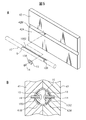
- FIG. FIG. 2A is a perspective view showing a state in which a screen is closed in an embodiment of an electronic device having a multi-divided housing
- FIG. It is an open perspective view showing a state in which one screen is formed on a flat surface.
- FIG. 3A illustrates a partial operation of the multi-divided housing coupling device according to the embodiment, in which FIG. 3A is a perspective view illustrating two housings that are overlapped and closed, and FIG. 3B is a diagram illustrating two housings illustrated in FIG.
- FIG. 3C is a perspective view showing a state in which the body slides using the rotating shaft of the coupling device, and FIG. 3C shows one of the two housings shown in FIG. 3B using the rotating shaft of the coupling device and 180 degrees with respect to the other.
- FIG. 3D is a perspective view showing a state in which the rotation of one casing shown in FIG. 3C is finished and the display surfaces of the two casings are flattened.
- FIG. 4A is a front view of the first casing
- FIG. 4A is a front view of the first casing
- FIG. 4B is a right side of the first casing shown in FIG. 4A.
- FIG. 4C is a front view of the second casing
- FIG. 4D is a left side view of the second casing shown in C
- FIG. 4E is a coupling built in between the first and second casings.
- 4F is a cross-sectional view taken along line FF in FIG. 4E
- FIG. 4G is a bottom view of the rotary shaft shown in FIG. 4E
- FIG. 4H is a cross-sectional view taken along line HH in FIG.
- FIG. 4I is a plan view of the sliding assist member inserted into the rotating shaft shown in FIGS. 4E and 4G
- FIG. 4J is a side view of the sliding assist member shown in FIG. 4I.
- FIG. 4I is a plan view of the sliding assist member inserted into the rotating shaft shown in FIGS. 4E and 4G
- FIG. 4J is a side view of the sliding assist member shown in FIG. 4I
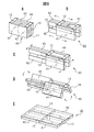
- FIG. 5A is an assembly perspective view showing a state in which the rotating shaft shown in FIG. 4E is attached to the second housing using a sliding assist member
- FIG. 5B is a perspective view showing that the rotating shaft shown in FIG. 4E and FIG. It is sectional drawing which shows the state attached to the 1st and 2nd housing
- 2A shows a process in which the electronic device shown in FIG. 2A is transformed into the state shown in FIG. 2B.
- FIG. 6A is a perspective view showing a state in which four housings are overlapped
- FIG. 6B shows the step shown in FIG.
- FIG. 6C is a perspective view showing a state in which the outer two casings of the four casings start to slide relative to the inner two casings, and FIG.
- FIG. 6C shows the outer side of the four casings shown in FIG. 6B.
- FIG. 6D is a perspective view showing a state where the two casings have finished sliding with respect to the two inner casings, and FIG. 6D shows two outer casings and two inner casings from the state shown in FIG.
- FIG. 6E is a perspective view showing a state in which rotation about the rotation axis of the hinge is started, and FIG. 6E shows that the outer two cases and the two inner cases are further rotated from the state shown in FIG. It is a perspective view which shows the state rotated.
- 2A is a front view of a process in which the electronic device shown in FIG. 2A is transformed into the state shown in FIG. 2B.
- FIG. 7A is a front view corresponding to FIGS.
- FIG. 7C is a front view showing a state in which the outer two housings and the inner two housings start to rotate around the rotation axis of the hinge, respectively, and FIG. 7C shows the two outer housings from the state shown in FIG. 7B.
- FIG. 7D is a front view showing a state in which the body and the inner two housings are further rotated, and FIG. 7D is a view showing the outer two housings and the two inner housings being further rotated from the state shown in FIG. It is a front view which shows the state rotated by each.
- FIG. 7D is a front view showing a state in which the outer two housings and the inner two housings start to rotate around the rotation axis of the hinge, respectively
- FIG. 7C shows the two outer housings from the state shown in FIG. 7B.
- FIG. 7D is a front view showing a state in which the body and the inner two housings are further rotated
- FIG. 7D is a view showing the outer two housings and the two inner housings
- FIG. 8A is a perspective view of an electronic device including eight housings formed by joining end surfaces on the side where the inner housing of the electronic device including four housings illustrated in FIG. 6A is not pulled out.
- FIG. 8B is a perspective view showing a state in which the outer two cases out of the four cases shown in FIG. 8A start to slide in opposite directions with respect to the inner two cases, corresponding to FIG. 6B.
- FIG. 8C is a perspective view showing a state in which the two outer casings of the four casings shown in FIG. 8B have finished sliding with respect to the inner two casings, and corresponds to FIG. 6C. It is a figure to do.
- FIG. 9A is a perspective view showing a state in which the outer two housings and the inner two housings have started to rotate around the rotation axis of the hinge from the state shown in FIG. 8C, and corresponds to FIG. 6D.
- FIG. 9B is a perspective view showing a state in which the outer two housings and the inner two housings are further rotated from the state shown in FIG. 9A and rotated 180 degrees each, corresponding to FIG. 6E. It is a figure to do.
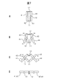
- FIG. 11A shows the first and second casings to which the multi-divided casing coupling device having the slide assist mechanism shown in FIG.
- FIG. 11B is a side view showing a state in which the housing has been slid and rotated
- FIG. 11B is a side view showing a state in which the second housing is rotated 180 degrees around the rotation axis with respect to the first housing from the state of FIG.
- FIG. 12A is a side view showing the operation of the multi-divided housing coupling device provided with the slide assist mechanism when the second housing slides in the direction approaching the first housing from the state of FIG. 11B
- 12B is a side view illustrating the operation of the multi-divided housing coupling device having the slide assist mechanism when the second housing in FIG. 12A further slides with respect to the first housing and the two housings overlap each other.
- FIG. 13A is an assembly perspective view showing the coupling of the spring and the piece member of the slide assist mechanism used in the coupling device of another embodiment
- FIG. 13B is the spring and the piece member of the slide assist mechanism used in the coupling device of another embodiment. It is a side view which shows the coupling
- FIG. 14A is a partial perspective view showing a hinge that joins the second housing and the third housing in the coupling device of another embodiment
- FIG. 14B shows the first housing and the first housing in the coupling device of another embodiment. It is a fragmentary perspective view which shows the hinge which couple
- FIG. 2A discloses a closed state of an embodiment of an electronic device 40 having a multi-part housing
- FIG. 2B shows the electronic device 40 in an opened state using a coupling device described below.
- the electronic device 40 of this embodiment includes first to fourth divided housings 41 to 44.
- the divided casings 41 to 44 are hereinafter simply referred to as casings 41 to 44.
- the first to fourth casings 41 to 44 have screens (displays) 41D to 44D, respectively.
- the displays 41D to 44D are close to each other and form one large screen. If any one of the first to fourth casings 41 to 44 is provided with a control device that displays an image of a quarter of one display image in synchronization with another screen, one A large image can be displayed on a large screen.
- the first to fourth casings 41 to 44 are a pair of the first and second casings 41 and 42, and the third and fourth casings 43 and 44 are It is a pair.
- the second casing 42 and the third casing 43 are disposed adjacent to each other, and one of the end faces in the longitudinal direction of the second casing 42 and the third casing 43 (the lower side in FIG. 2A).
- a first hinge 11 (hereinafter simply referred to as a hinge 11) for connecting the end faces is attached to the end face on the side.
- the second casing 42 and the third casing 43 can be opened in a V shape with the hinge 11 as a rotation axis.
- the first and fourth casings 41 and 44 arranged outside the electronic device 40 are connected to the other end surface in the longitudinal direction (the upper end surface in FIG. 2A) by connecting the end surfaces to each other.
- a hinge 12 (hereinafter simply referred to as hinge 12) is attached.
- the first casing 41 and the fourth casing 44 can be opened in a V shape with the hinge 12 as a rotation axis.
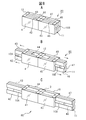
- FIG. 3A shows a state in which the first and second casings 41 and 42 are overlapped and closed.
- the rotating shaft 10 is accommodated in the overlapping surface of the first and second casings 41 and 42.
- the first and second casings 41 and 42 can be slid and rotated by the rotation shaft 10.
- FIG. 3B shows a state in which the second housing 42 slides in the direction P away from the first housing 41 shown in FIG. 3A using the rotating shaft 10.
- the length of the rotating shaft 10 protruding inward is the same.
- FIG. 3C shows a state in which the first housing 41 and the second housing 42 shown in FIG. 3B have slid to the maximum extent (sliding complete state, hereinafter also referred to as full sliding state). In the fully slid state, adjacent ends of the first casing 41 and the second casing 42 do not overlap with each other, and the second casing 42 is indicated by an arrow T around the rotation axis 10.
- the first housing 41 can be rotated 180 degrees.
- FIG. 3D shows a state in which the second housing 42 is rotated 180 degrees around the rotation axis 10 with respect to the first housing 41 from the state shown in FIG. 3C.
- the second housing 42 rotates 180 degrees around the rotation axis 10
- one surface of the housings of the first and second housings 41 and 42 becomes flat, and this surface is displayed on the display 41D. , 42D, two flat screens can be obtained.
- the side surface of the rotating shaft 10 is exposed on the back side of the flat two screens.
- the rotation shaft 10 does not have to be a perfect columnar shape, but may have a shape that allows the second housing 42 to rotate 180 degrees with respect to the first housing 41.
- FIG. 4A is a front view of the first casing 41
- FIG. 4B is a right side view of the first casing 41 shown in FIG. 4A.
- the first housing 41 is formed with a circumferential groove 41M at the longitudinal center. Further, there is a screw hole 41A for attaching a sliding auxiliary member described later at a predetermined position of the circumferential groove 41M.
- 4C is a front view of the second casing 42, and FIG.
- FIG. 4D is a left side view of the second casing 42 shown in FIG. 4C.
- the second housing 42 is formed with a circumferential groove 42M at the center in the longitudinal direction. Further, there is a screw hole 42A for attaching a sliding auxiliary member described later at a predetermined position of the circumferential groove 42M.
- FIG. 4E is a plan view of the rotary shaft 10 accommodated in the grooves 41M and 42M on the overlapping surfaces of the first and second casings 41 and 42
- FIG. 4F is a cross-sectional view taken along the line FF in FIG. 4E.
- 4G is a bottom view of the rotating shaft 10 shown in FIG. 4E
- FIG. 4H is a cross-sectional view taken along the line HH in FIG. 4G.
- the length of the rotating shaft 10 is the same as the length of the first and second casings 41 and 42 in the longitudinal direction.
- the rotating shaft 10 has a hollow tube shape, and as shown in FIG.
- slits 10S1 and 10S2 are provided in the longitudinal direction on the front side and the back side of the wall surface.
- a hole SH having a large diameter provided at one end of each of the slits 10S1 and 10S2 is for inserting a screw head or a screwdriver.
- An annular slit 10R extending in the circumferential direction is provided at the other end of the slit 10S2. As shown in FIG. 4H, the annular slit 10R has a length sufficient to move the screw that has moved the slit 10S2 to the opposite side by 180 degrees.
- FIG. 4I is a plan view of the sliding auxiliary member 13 inserted into the hollow rotary shaft 10 shown in FIGS. 4E to 4H
- FIG. 4J is a side view of the sliding auxiliary member 13 shown in FIG. 4I. is there.
- One surface in the longitudinal direction of the sliding auxiliary member 13 is a flat surface, and the other surface is a circumferential surface along the inner peripheral surface of the hollow rotating shaft 10.
- the sliding assisting member 13 is provided with a hole 13A penetrating from a flat surface to a circumferential surface for inserting a screw.
- One of the sliding assisting members 13 is attached to a screw hole 41A at a predetermined position of the circumferential groove 41M by a screw inserted through the slit 10S1 of the rotating shaft 10.
- the other one of the sliding assistance members 13 is attached to a screw hole 42A at a predetermined position of the circumferential groove 42M by a screw that passes through the slit 10S2 of the rotating shaft 10.
- FIG. 5A is an assembly perspective view showing a state in which the rotating shaft 10 shown in FIG. 4E is attached to the second casing 42 using the sliding assisting member 13.
- the sliding auxiliary member 13 is inserted into the hollow rotary shaft 10 in advance, and the screw 14 for attaching the sliding auxiliary member 13 to the second housing 42 is, for example, the end of the slit 10S1 shown in FIG. 4G. It is inserted into the rotary shaft 10 through the hole SH in the section. Further, the screw 14 attached to the sliding assisting member 13 is screwed to the second housing 42 by a driver inserted through the hole SH.
- the second casing 42 can move in the longitudinal direction with respect to the rotating shaft 10 and the rotating shaft 10 can be moved by the slit 10R. It can be rotated 180 degrees with respect to. Since the attachment of the other sliding assisting member 13 to the first casing 41 using the screw 14 can be performed in the same manner, the illustration is omitted.
- FIG. 5B is a cross-sectional view showing a state where the rotating shaft 10 shown in FIGS. 4E and 4F is attached to the first and second casings 41 and 42 by the sliding auxiliary member 13 and the screw 14.
- the first and second casings 41 and 42 have a boss portion to which the screw 14 is attached and other circuit parts, but these are not shown here, and the rotary shaft 10, the sliding auxiliary member 13, Only the positional relationship between the screw 14 and the first and second casings 41 and 42 is shown.
- the first casing 41 can only move in the longitudinal direction with respect to the rotation shaft 10, and the second casing 42 is long with respect to the rotation shaft 10.
- Directional movement and 180 degree rotation are possible.
- the lengths of the slits 10S1 and 10S2 and the positions of the screw holes 41A and 42A in the grooves 41M and 42M are determined by rotating the first and second casings 41 and 42 as shown in FIG. What is necessary is just to determine that 10 protrudes in the groove
- the first and second casings 41 and 42 have been described above, the third and fourth casings 43 and 44 have the same structure as the first and second casings 41 and 42 as described above. Therefore, the same operation as that of the first and second casings 41 and 42 is possible.
- FIG. 6A to FIG. 6E and FIG. 7A to FIG. 7C show a process in which the electronic device 40 including the first to fourth casings 41 to 44 shown in FIG. 2A is transformed into the state shown in FIG. 2B.
- the rotary shaft 10 is depicted as a simple columnar member, like the rotary shaft 10 shown in FIG. FIG. 6A shows a state in which the first to fourth casings 41 to 44 are overlapped.
- the longitudinal side surfaces of the second and third housings 42 and 43 are coupled by the hinge 11, and the longitudinal side surfaces of the first and fourth housings 41 and 44 are coupled by the hinge 12. ing.
- FIG. 6B shows that the first and fourth casings 41 and 44 on the outer side of the four casings 41 to 44 shown in FIG. 6A are connected to the second and third casings 42 and 43 on the inner side.
- the state which started to slide in the direction shown by the arrow is shown.
- the lengths of the rotary shafts 10 protruding toward the first and fourth casings 41 and 44 are the same.
- FIG. 6C shows a full slide state in which the outer first and fourth casings 41 and 44 shown in FIG. 6B have finished sliding with respect to the inner second and third casings 42 and 43. Yes.
- the end portions of the first and fourth casings 41 and 44 on the second and third casings 42 and 43 side, and the first and second casings 42 and 43 side by side. 4 does not overlap with the end portions of the casings 41 and 44 on the side.
- the length of the rotary shaft 10 protruding from the first and fourth housings 41 and 44 to the second and third housings 42 and 43 side, and the first from the second and third housings 42 and 43 to the first. And the length of the rotating shaft 10 which protrudes to the 4th housing
- casing 41 and 44 side is the same.
- FIGS. 7A to 7D are views of the state shown in FIGS. 6A to 6E viewed from the longitudinal direction of the electronic device 40.
- FIGS. 6A to 6C are all the same when viewed from the longitudinal direction of the electronic device 40, and this is shown in FIG. 7A.
- FIG. 7B shows a state where the first and fourth housings 41 and 44 and the second and third housings 42 and 43 are slightly expanded from the state shown in FIG. 6C.
- the first and fourth casings 41 and 44 and the second and third casings 42 and 43 are expanded, the first to fourth casings 41 to 44 all rotate around the rotation axis 10. I understand that.
- FIG. 7C shows a state in which the first and fourth casings 41 and 44 and the second and third casings 42 and 43 are further expanded from the state shown in FIG. 6D.
- FIG. 7D shows a view of the state shown in FIG. 6E viewed from the longitudinal direction of the electronic device 40. From FIG. 7D, it can be seen that the surfaces on which the displays of the first to fourth casings 41 to 44 after the rotation are completed are fully flat.
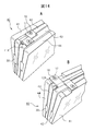
- FIG. 8A shows an electronic device 80 formed by using two of the electronic devices 40 and joining the end surfaces of the external housing on the side where the internal housing is not pulled out.
- the electronic device 80 includes first to eighth housings 41 to 48, and the first to fourth housings 41 to 44 have the same structure as the electronic device 40.
- the fifth to eighth casings 45 to 48 have a structure in which the first to fourth casings 41 to 44 rotate the electronic device 40 by 180 degrees in the longitudinal direction. That is, the fifth housing 45 has the same structure as the fourth housing 44, the sixth housing 46 has the same structure as the third housing 43, and the seventh housing 47 has the same structure as the second housing 42.
- the same structure and the eighth casing 48 have the same structure as the first casing 41.
- the end surface on the 48 side and the end surface on the fourth housing 44 side of the eighth housing 48 are joined.
- FIG. 8B shows that the second and third casings 42 and 43 are pulled out to one side with respect to the first and fourth casings 41 and 44, respectively.
- the sixth and seventh housings 46 and 47 are pulled out to the other with respect to the fifth and eighth housings 45 and 48.
- 8C shows that the second and third housings 42 and 43 are fully slid with respect to the first and fourth housings 41 and 44, and the sixth and fourth housings 45 and 48 are sixth and sixth. A state in which the seventh casings 46 and 47 are fully slid is shown.
- FIG. 8C shows an electronic device 80 corresponding to the electronic device 40 shown in FIG. 6C.
- 9A shows the second and third housings 42 and 43, the first and fourth housings 41 and 44, the fifth and eighth housings 45 and 48, and the sixth housing from the state shown in FIG. 8C. And the seventh casings 46 and 47 are rotated around the rotation axes of the corresponding hinges 11 and 12, respectively. Since the end portions of the first housing and the fifth housings 41 and 45 and the fourth housing and the eighth housings 44 and 48 are joined, they move together.
- 9B shows the second and third housings 42 and 43, the first and fourth housings 41 and 44, the fifth and eighth housings 45 and 48, and the sixth and sixth housings from the state shown in FIG. 9A. 7 shows a state in which the casings 46 and 47 of the seven are rotated 180 degrees.
- the second and third casings 42 and 43, the first and fourth casings 41 and 44, the fifth and eighth casings 45 and 48, and the sixth and seventh casings 46 and 47 are 180 respectively. When it is rotated, a full flat screen of 8 screens is completed.
- the disclosed electronic devices 40 and 80 can form a flat large screen by expanding a plurality of stacked casings with a coupling device, so that the size is small when carrying and a large screen is displayed when displaying an image. Can be realized. Further, in the embodiment shown in FIGS. 8A to 8C and FIGS. 9A and 9B, since two electronic devices 40 are joined as they are, the display screen shown in FIG. 9B is horizontally long. If the aspect ratio is changed, a screen with an aspect ratio of 4: 3 or 16: 9 can be realized.
- FIG. 10 is an assembled perspective view showing a partial structure of a multi-divided housing coupling device provided with the slide assist mechanism 30.
- FIG. 10 shows first and second housings 41 and 42 in the electronic device 40. As shown in FIG. Shown is a slide assist mechanism 30 that is attached to the.
- the first and second casings 41 and 42 are shown in an open state, which corresponds to the state of FIG. 3D of the above-described embodiment viewed from the back side.
- the rotating shaft 10C shown in FIG. 10 corresponds to the rotating shaft 10 shown in FIG. 3C, for example.
- On the overlapping surface side of the first housing 41 there is a groove 41N having the same width and the same depth and extending in the longitudinal direction.
- a rectangular mounting recess 41T for mounting a mounting plate 41P described later is provided in the middle of the groove 41N.
- the second casing 42 has the same depth but is continuously provided with a wide groove 42W and a narrow groove 42N.
- the depth of the wide groove 42 ⁇ / b> W is the same as the groove 41 ⁇ / b> N in the first housing 41.
- One wall surface of the wide groove 42 ⁇ / b> W is continuous with one wall surface of the groove 41 ⁇ / b> N in the first housing 41.
- the narrow groove 42 is provided so as to overlap the groove 41N when the second casing 42 is rotated by 180 degrees around the rotation axis 10C and superimposed on the first casing 41.
- the rectangular attachment recessed part 42T for attaching two brackets 42B is provided in two places.
- the slide assist mechanism 30 includes a main body 33, an annular part 35, a mounting plate 41P, two brackets 42B, and a rotating shaft 10C.
- the main body 33 has a rectangular plate shape, the length of the main body 33 is the same as the lengths of the first and second casings 41 and 42, and the width of the main body 33 is a groove in the first casing 41. It is a width that can slide within 41N.
- the length of the rotating shaft 10 ⁇ / b> C is the same as the length of the main body 33.
- the thickness of the main body 33 is such that when the first and second casings 41 and 42 overlap each other, the thickness can slide in the space formed by the grooves 41N and 42N, that is, the depth of the groove 41N. It is about twice as thick. In practice, there is a cover on the surface of the main body 33 facing the grooves 41N and 42N, but this cover is not shown.
- the main body 33 includes an oval concave portion 36 and a cutout portion 37 that is a space that is communicated with the concave portion 36 and cut out to one long side portion of the main body 33.
- a guide member 34 is provided in the recess 36, and both end portions of the guide member 34 are semicircular, and a semicircular passage is formed between both ends of the recess 36.
- a slit 36S having stepped portions 36D at both ends is formed on the opposite side of the notched portion 37 of the guide member 34, and a piece member described later is accommodated in a portion adjacent to the stepped portion 36D of the slit 36S. There are locking recesses 51 and 52 to stop.
- the annular part 35 is a belt-like member, and the first slide member 31 is attached to the inner peripheral surface thereof, and the second slide member 32 is attached to the outer peripheral surface thereof.
- the lengths of the first and second slide members 31 and 32 are the same. Further, the length of the annular part 35 from one end of the first slide member 31 to one end of the second slide member 32 and the second slide from the other end of the first slide member 31. The length of the annular part 35 to the other end of the member 32 is also the same.
- the annular part 35 is incorporated in the recess 36 of the main body 33 with both ends inserted into the semicircular passage described above, and the first slide member 31 can move in the slit 36S of the guide member 34. Further, the second slide member 32 can move in the cutout portion 37 in a state where the annular part 35 is incorporated in the recess 36.
- a mounting plate 41P is attached to the first housing 41 side of the first slide member 31 with screws 15, and the mounting plate 41P to which the first slide member 31 is attached is attached to the first housing 41 with screws 15. Is fixed to the mounting recess 41T. Since the recess 32A is provided in the second slide member 32, the rotary shaft 10C is inserted through the shaft insertion hole 38 provided in the main body 33 with the two brackets 42B positioned in the recess 32A. The rotary shaft 10C is passed through the hole 42H provided in the bracket 42B. The rotary shaft 10C passing through the hole 42H provided in the bracket 42B passes through the notch 37 and then passes through the shaft insertion hole 38 provided on the opposite side of the main body 33. When the bracket 42B inserted through the rotary shaft 10C is positioned at both ends of the recess 32A, the bracket 42B can be fixed to the mounting recess 42T provided in the second housing 42 with the screw 15.
- the annular part 35 is a belt-like member in this embodiment, but may be a linear member using a wire or the like.
- the annular component 35 can be integrally formed by cutting out the first and second slide members 31 and 32 from a synthetic resin plate. Also, the first and second slide members 31 and 32 and the annular part 35 are prepared separately, and the annular part 35 is connected to the first and second slide members 31 and 32. Can be made.
- one end of the first slide member 31 is slit. It is located within the stepped portion 36D on the first housing 41 side of 36S.
- the assist spring member 18 including the tension spring 19 and the piece member 20 is attached in the slit 36S.
- one of the piece members 20 is inserted into the locking recess 51, the tension spring 19 is inserted into the slit 36S between the first slide member 31 and the guide member 34, and the other of the piece members 20 is the first one.
- the end of the slide member 31 is locked. This state is the state shown in FIG. 11A.
- the assist spring member 18 includes a tension spring 19 that is an elastic body, and a piece member 20 that is swingably attached to both ends of the tension spring 19.
- the diameter of the piece member 20 is larger than the width of the tension spring 19 in the short direction.
- the piece member 20 forms a notch 21 by cutting a part of a disk-shaped main body 23 into an arc shape, and a post 22 near the outer periphery of the main body 23 of the notch 21. Is a projecting project.
- the hook portion 19H of the tension spring 19 is attached to the post 22.
- FIG. 13B shows the tension spring 19 shown in FIG. 13A and the piece members 20 attached to both ends thereof.
- the piece member 20 can swing with respect to the tension spring 19.
- the piece member 20 has a hook portion (post 22) capable of locking the hook portion 19H of the spring 19 in part.
- the piece member 20 may have a circular shape or the like so that the piece member 20 can be rolled when the part that locks the piece member 20 is replaced as will be described later.
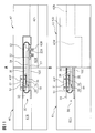
- FIG. 11A in a state where the slide assist mechanism 30 is attached to the first and second casings 41 and 42, the second casing 42 has a rotational axis 10C relative to the first casing 41. And the bracket 42B can be rotated 180 degrees.
- FIG. 11B shows a state in which the second housing 42 is rotated 180 degrees with respect to the first housing 41 by the rotating shaft 10C and the bracket 42B.
- the state shown in FIG. 11B corresponds to the state shown in FIG. 3C in the above-described embodiment.
- the groove 41N of the first housing 41 and the groove 42N of the second housing 42 are connected in a straight line.
- the slide assist mechanism 30 causes the grooves 41N of the first housing 41 and the grooves of the second housing 42 to be applied. Since 42N is slid, the 1st housing
- FIG. 11B in the state where an external force is started to be applied to both ends of the first housing 41 and the second housing 42, one piece member 20 of the assist spring member 18 is locked to the locking recess 51. The other piece member 20 is locked to one end of the first slide member 31. Accordingly, the tension spring 19 extends due to the movement of the first casing 41 in the direction approaching the second casing 42. When the first casing 41 further approaches the second casing 42, the other end of the first slide member 31 passes through the position of the locking recess 51.
- FIG. 12A shows a state in which the first casing 41 and the second casing 42 are close to the half of the total length from the state of FIG. 11B, and corresponds to the state of FIG. 3B of the above-described embodiment. .
- the second housing 42 is not shown, and only its position is indicated by a two-dot chain line.
- the first casing 41 and the second casing 42 approach each other while the piece members 20 at both ends are locked to both ends of the first slide member 31.
- the tension spring 19 is extended, and the piece member 20 is applied with a pulling force in a direction approaching the other piece member 20.
- FIG. 12B shows a state in which the first and second casings 41 and 42 overlap each other, and corresponds to the state shown in FIG. 3A of the above-described embodiment.
- the slide assist mechanism 30 performs the operation from the state shown in FIG. 12A to the state shown in FIG. 11B. .
- an assist force in the direction of moving the first and second casings 41 and 42 away is generated by the tension spring 19, and The force when the second casings 41 and 42 are in the full slide state is reduced.
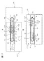
- FIG. 14A shows the hinge 11 that couples the second housing 42 and the third housing 43 in the electronic device 40 including the coupling device of another embodiment.
- One end of the hinge 11 is fixed to the end of the second casing 42 by a screw 16, and the other end of the hinge 11 is fixed to the end of the third casing by a screw 16.
- the second casing 42 and the third casing 43 can rotate around the rotation axis 11 ⁇ / b> A of the hinge 11.
- FIG. 14B shows the hinge 12 that couples the first housing 41 and the fourth housing 44 in the electronic device 40 including the coupling device of another embodiment.
- One end of the hinge 12 is fixed to the end of the first housing 41 by a screw 16, and the other end of the hinge 12 is fixed to the end of the fourth housing by a screw 16.
- the first casing 41 and the fourth casing 44 can rotate around the rotation axis 12 ⁇ / b> A of the hinge 12.
- the electronic devices 40 and 80 having the multi-divided housing coupling device of the present application can form a full flat large screen in a state where a plurality of housings having screens are coupled, and rotate. By sliding each case in a sliding motion, it is possible to make it convenient for carrying.
Abstract
分割された筐体を展開した時に得られる表示画面がフルフラットになる電子装置の多分割筐体の結合装置であり、重なった第1から第4の筐体の第1と第2の筐体間と第3と第4の筐体間に、重なった筐体をスライド後に一方を他方に対して180度回転可能な回転軸を設けると共に、第2と第3の筐体の端面を回転可能に結合する第1のヒンジと、第1と第4の筐体の反対側の端面を結合する第2のヒンジとを設け、回転軸により、第1と第4の筐体に対して第2と第3の筐体をスライドさせ、スライド完了状態で第1と第2のヒンジにより第2と第3の筐体及び第1と第4の筐体をそれぞれ回転軸の回りに回転させながら開いて1つの平坦面を形成するようにした多分割筐体の結合装置である。
Description
本出願は多分割筐体の結合装置及び該結合装置を備えた電子装置に関する。
近年、携帯電話等の情報端末の小型、薄型化に伴い、携帯性、操作性、表示の見やすさを良くする理由で、キーボード部等の固定部に対し、ディスプレイ部等の可動部をスライドさせる製品がある。図1Aは固定筐体(下側筐体)1に対して、可動筐体(上側筐体)2が重なり合った状態の情報端末3を示すものである。この情報端末3は図1Bに示すように、固定筐体1に対して、可動筐体2がスライドさせた状態で使用される。このような形態の情報端末3としては、例えば、携帯電話機、携帯端末(タブレットコンピュータ等の小型コンピュータ)、或いはゲーム機等がある。
ところが、このような情報端末3では、図1Bに示されるように、固定筐体1に対して、可動筐体2をスライドさせる際に、筐体の構造上、固定筐体1と可動筐体2とが開き切った状態(フルスライド状態)で両者の間に重なり部分Lが必要であった。このため、可動筐体2の固定筐体1に対するスライド量は、スライドする方向の筐体長さの3分の2程度までであった。この構造は、下側の固定筐体1をキーボードにする場合は良かったが、下側の固定筐体1もディスプレイ部にする場合は、重なり部分Lがあるために充分なディスプレイの広さを得ることができなかった。
これに対して、図1Cに示すような、フルスライド時に固定筐体1に対して可動筐体2が平坦(フルフラット)になる構造の情報端末4が、例えば、特許文献1や特許文献2に開示されている。特許文献1では、固定筐体(第1筐体)と可動筐体(第2筐体)の側面を連結する連結駒があり、連結駒にある2本のピンの一方が可動筐体に枢支され、他方が固定筐体にスライド可能に係合している。また、特許文献2では、固定筐体(第2筐体)と可動筐体(第1筐体)がリンク機構で接続されており、可動筐体が固定筐体に対してフルスライドして表示面がフルフラットになるようになっている。
携帯端末をメールやツイッター等の用途に使用する場合は、スマートフォン等の小型サイズで良いが、電子書籍になった雑誌や新聞を見る場合には、画面の大きいタブレットが適している。そして、スマートフォン型の携帯電話機とタブレットの両方の端末を持ち歩くのは大変なので、タブレットで兼用したいというニーズがある。
しかしながら、これまで2画面を1つの平坦な画面にする端末はあったが、より多くの画面、例えば4画面を結合してタブレットと同等のサイズを実現するような端末は無かった。また、分割された4つの筐体を結合して多画面の情報端末ができたとしても、図1Dに示すように、情報端末5を構成する4つの分割された筐体5A~5Dの画面に段差が生じるという課題があった。そして、段差が生じると、画面が見づらく、またタッチ動作(ワイプ動作)の際に支障になってしまう。
1つの側面では、本出願は多数の分割された筐体を結合して1つの画面を形成する情報端末などの電子装置において、分割された筐体を結合した時に、結合された筐体の画面がフルフラットになる多分割筐体の結合装置を提供することを目的とする。また、分割された筐体を結合した時に、結合された筐体の画面がフルフラットになる多分割筐体の結合装置を備えた電子装置の提供を目的とする。
実施形態の一観点によれば、多分割筐体の結合装置は、第1から第4の4つの筐体をこの順に重ね合わせた時に、第1と第2の筐体の間と第3と第4の筐体の間にそれぞれ配置され、重なった筐体をスライドさせた後に、一方を他方に対して180度回転させる回転軸と、第2と第3の筐体の、回転軸と平行な方向に露出する端面の一方同士を結合する第1のヒンジと、第1と第4の筐体の回転軸と平行な方向に露出する端面の、第1のヒンジ側の端面と反対側の端面同士を結合する第2のヒンジとを備え、回転軸により、第1と第4の筐体に対して第2と第3の筐体をスライドさせ、スライド完了状態で第1と第2のヒンジにより第2と第3の筐体及び第1と第4の筐体をそれぞれ回転軸の回りに回転させながら開いて1つの平坦面を形成することを特徴としている。
また、実施形態の他の観点によれば、多分割筐体の結合装置を備えた電子装置は、第1から第4の4つの筐体をこの順に重ね合わせた時に、第1と第2の筐体の間と第3と第4の筐体の間にそれぞれ配置され、重なった筐体をスライドさせた後に、一方を他方に対して180度回転させる回転軸と、第2と第3の筐体の、回転軸と平行な方向に露出する端面の一方同士を結合する第1のヒンジと、第1と第4の筐体の回転軸と平行な方向に露出する端面の、第1のヒンジ側の端面と反対側の端面同士を結合する第2のヒンジとを備え、回転軸により、第1と第4の筐体に対して第2と第3の筐体をスライドさせ、スライド完了状態で第1と第2のヒンジにより第2と第3の筐体及び第1と第4の筐体をそれぞれ回転軸の回りに回転させながら開いて1つの平坦面を形成する多分割筐体の結合装置を備えた電子装置であって、第1から第4の筐体の回転軸が設けられている面と反対側に面に表示画面を備え、1つの平坦面が1つの表示画面となることを特徴としている。
以下、添付図面を用いて本出願に係る多分割筐体の結合装置及び結合装置を備えた電子装置の実施の形態を、具体的な実施例に基づいて詳細に説明する。
図2Aは多分割筐体を備えた電子装置40の一実施形態の閉じた状態を開示するものであり、図2Bは後述する結合装置を使用して開いた状態の電子装置40を示している。この実施形態の電子装置40は、第1から第4の4つの分割筐体41~44を備えている。分割筐体41~44は以後単に筐体41~44と記す。第1から第4の4つの筐体41~44にはそれぞれ画面(ディスプレイ)41D~44Dがある。第1から第4の4つの筐体41~44が開いた状態では、各ディスプレイ41D~44Dが近接し、1つの大画面となる。第1から第4の筐体41~44の何れかに、1つの表示画像の4分の1の画面分の画像を他の画面と同期させて表示する制御装置を設けておけば、1つの大画面に大きな画像を表示することができる。
図2Aに示すように、第1から第4の4つの筐体41~44は、第1と第2の筐体41、42がペアであり、第3と第4の筐体43、44がペアとなっている。第1と第2の筐体41、42の重なり面にはそれぞれ円周溝41M、42Mがあり、円周溝41M、42Mの中に回転軸10が収容されている。同様に、第3と第4の筐体43、44の重なり面にもそれぞれ円周溝43M、44Mがあり、円周溝43M、44Mの中に結合装置である回転軸10が収容されている。
電子装置40では、第2の筐体42と第3の筐体43が隣接配置されており、第2の筐体42と第3の筐体43の長手方向の端面の一方(図2Aでは下側の端面)には、端面同士を接続する第1のヒンジ11(以後単にヒンジ11と記す)が取り付けられている。第2の筐体42と第3の筐体43は、このヒンジ11を回転軸にしてV字状に開くことができる。また、電子装置40の外側に配置された第1と第4の筐体41、44には、長手方向の端面の他方(図2Aでは上側の端面)には、端面同士を接続する第2のヒンジ12(以後単にヒンジ12と記す)が取り付けられている。第1の筐体41と第4の筐体44は、このヒンジ12を回転軸にしてV字状に開くことができる。これらの動作については後述する。
図2Aに示した第1と第2の筐体41、42と、第3と第4の筐体43、44は、回転軸10による動作は全く同じであるので、ここでは図3を用いて電子装置40における第1と第2の筐体41、42の動作について説明する。図3Aは第1と第2の筐体41、42が重ね合わされて閉じた状態を示している。前述のように第1と第2の筐体41、42の重なり面には回転軸10が収容されている。第1と第2の筐体41、42は、回転軸10によりスライド動作と回転動作が可能である。
図3Bは、図3Aに示した第1の筐体41に対して、第2の筐体42が回転軸10を使用して離れる方向Pにスライドする状態を示している。ここで、第1の筐体41から突出して第2の筐体42の溝42M内に突出する回転軸10の長さと、第2の筐体42から突出して第1の筐体41の溝41M内に突出する回転軸10の長さは同じである。図3Cは、図3Bに示した第1の筐体41と第2の筐体42が最大限スライドした状態(スライド完了状態であり、以後フルスライド状態とも記す)を示している。フルスライド状態では、第1の筐体41と第2の筐体42の隣接する端部同士は重なり合っておらず、第2の筐体42は、回転軸10の回りに、矢印Tで示すように第1の筐体41に対して180度回転することができる。
図3Dは、図3Cに示した状態から、第2の筐体42が回転軸10の回りに第1の筐体41に対して180度回転した状態を示すものである。第2の筐体42が回転軸10の回りに180度回転すると、第1と第2の筐体41、42の筐体の一方の面が平坦(フラット)になるので、この面をディスプレイ41D、42Dとすれば、フラットな2画面が得られる。このとき、フラットな2画面の裏面側には回転軸10の側面が露出している。なお、回転軸10は、完全な円柱状でなくても、第1の筐体41に対して第2の筐体42が180度回転できる形状であれば良い。
次に、図4を用いて第1と第2の筐体41、42及び回転軸10の具体的な一実施形態を説明する。第3と第4の筐体43、44及び回転軸10の構造は、第1と第2の筐体41、42及び回転軸10の構造と全く同じであるのでその説明を省略する。図4Aは第1の筐体41の正面図であり、図4Bは図4Aに示した第1の筐体41の右側面図である。第1の筐体41には長手方向中央部に円周溝41Mが形成されている。また、円周溝41Mの所定位置には、後述する摺動補助部材を取り付けるためのネジ穴41Aがある。図4Cは第2の筐体42の正面図であり、図4Dは図4Cに示した第2の筐体42の左側面図である。第2の筐体42には長手方向中央部に円周溝42Mが形成されている。また、円周溝42Mの所定位置には、後述する摺動補助部材を取り付けるためのネジ穴42Aがある。
図4Eは第1と第2の筐体41、42の重なり合った面にある溝41M、42Mの中に収容される回転軸10の平面図であり、図4Fは図4EのF-F線における断面図である。また、図4Gは、図4Eに示した回転軸10の底面図であり、図4Hは図4GのH-H線における断面図である。回転軸10の長さは、第1と第2の筐体41、42の長手方向の長さと同じである。回転軸10は中空のチューブ状であり、図4Fに示すように、その壁面の表側と裏側に長手方向にスリット10S1、10S2が設けられている。スリット10S1、10S2の一方の端部に設けられた直径の大きな孔SHはネジ頭を挿通する、或いはネジを回すドライバを挿入するためのものである。スリット10S2の他方の端部には円周方向に伸びる環状のスリット10Rが設けられている。環状のスリット10Rは、図4Hに示すように、スリット10S2を移動してきたネジを180度反対側に移動させるだけの長さを備える。
図4Iは、図4E~図4Hに示した中空の回転軸10の中に挿入する摺動補助部材13の平面図であり、図4Jは図4Iに示した摺動補助部材13の側面図である。摺動補助部材13の長手方向の一方の面は平坦面であり、他方の面は中空の回転軸10の内周面に沿った円周面である。摺動補助部材13には、平坦面から円周面まで貫通する孔13Aが、ネジを挿通するために設けられている。摺動補助部材13の1つは、回転軸10のスリット10S1を挿通するネジによって、円周溝41Mの所定位置にあるネジ穴41Aに取り付けられる。摺動補助部材13の他の1つは、回転軸10のスリット10S2を挿通するネジによって、円周溝42Mの所定位置にあるネジ穴42Aに取り付けられる。
図5Aは、図4Eに示した回転軸10を、摺動補助部材13を使用して第2の筐体42に取り付ける様子を示す組立斜視図である。摺動補助部材13は先に中空の回転軸10内に挿入しておき、摺動補助部材13を第2の筐体42に取り付けるためのネジ14は、例えば図4Gに示したスリット10S1の端部にある孔SHを通して回転軸10内に挿入する。また、摺動補助部材13に取り付けられたネジ14は、孔SHを挿通したドライバによって第2の筐体42に螺着される。このようにして摺動補助部材13がネジ14によって第2の筐体42に取り付けられると、第2の筐体42は回転軸10に対して長手方向に移動できると共に、スリット10Rによって回転軸10に対して180度回転できる。もう1つの摺動補助部材13のネジ14を使用した第1の筐体41への取り付けも同様に行うことができるので図示を省略する。
図5Bは、図4E、図4Fに示した回転軸10が摺動補助部材13とネジ14によって第1と第2の筐体41、42に取り付けられた状態を示す断面図である。第1と第2の筐体41、42にはネジ14が取り付けられるボス部やその他の回路部品があるが、ここではこれらの図示を省略してあり、回転軸10、摺動補助部材13、ネジ14及び第1と第2の筐体41、42の位置関係のみを示してある。本図と図4E、図4Gから分かるように、第1の筐体41は回転軸10に対して長手方向の移動のみが可能であり、第2の筐体42は回転軸10に対して長手方向の移動と180度の回転が可能である。
なお、スリット10S1、10S2の長さとネジ穴41A、42Aの溝41M、42M内の位置は、図3Cに示すように、第1と第2の筐体41、42をフルスライドさせた時に回転軸10が同じ長さだけ溝41M、42M内に突出するように決めれば良い。以上、第1と第2の筐体41、42について説明したが、第3と第4の筐体43、44は、前述のように構造が第1と第2の筐体41、42と同じであるので、第1と第2の筐体41、42と同じ動作が可能である。
ここで、図2Aに示した第1から第4の筐体41~44を備えた電子装置40が、図2Bに示した状態に変形される過程を、図6Aから図6E及び図7Aから図7Dを用いて説明する。なお、説明を分かり易くするために、回転軸10は図3に示した回転軸10と同様に単なる円柱状の部材として描いてある。図6Aは第1から第4の4つの筐体41~44が重ね合わされた状態を示している。前述のように、第2と第3の筐体42、43の長手方向の側面がヒンジ11によって結合され、第1と第4の筐体41、44の長手方向の側面がヒンジ12によって結合されている。
図6Bは、図6Aに示した4つの筐体41~44の内、外側の第1と第4の筐体41、44を、内側の第2と第3の筐体42、43に対して矢印で示す方向にスライドさせ始めた状態を示している。ここで、第1と第4の筐体41、44から第2と第3の筐体42、43側に突出する回転軸10の長さと、第2と第3の筐体42、43から第1と第4の筐体41、44側に突出する回転軸10の長さは同じである。
図6Cは、図6Bに示した外側の第1と第4の筐体41、44が、内側の第2と第3の筐体42、43に対してスライドを完了したフルスライド状態を示している。フルスライド状態では、第1と第4の筐体41、44の第2と第3の筐体42、43側の端部と、第2と第3の筐体42、43の第1と第4の筐体41、44側の端部とは重なり合っていない。また、第1と第4の筐体41、44から第2と第3の筐体42、43側に突出する回転軸10の長さと、第2と第3の筐体42、43から第1と第4の筐体41、44側に突出する回転軸10の長さは同じである。
この状態から第1と第4の筐体41、44のヒンジ12が無い方の端部と、第2と第3の筐体42、43のヒンジ11が無い方の端部を矢印の方向に広げる。すると、第1と第4の筐体41、44と第2と第3の筐体42、43は、図6Dに示すように、回転軸10の回りに回転すると共に、ヒンジ12、11を中心にしてV字状に開いていく。第1と第4の筐体41、44及び第2と第3の筐体42、43を更に広げると、第1と第4の筐体41、44と第2と第3の筐体42、43は、回転軸10の回りに180度回転したところで全ての面が図6Eに示すようにフルフラットになる。フルフラットになった第1から第4の筐体41~44の面の裏面側には、ヒンジ11、12が露出している。
図6Aから図6Eに示した状態を、電子装置40の長手方向から見た図が図7Aから図7Dに示される。図6Aから図6Cに示した状態を電子装置40の長手方向から見た図は全て同じであり、これが図7Aに示される。図7Bは、図6Cに示した状態から第1と第4の筐体41、44及び第2と第3の筐体42、43を僅かに広げた状態を示している。第1と第4の筐体41、44及び第2と第3の筐体42、43を広げると、第1から第4の筐体41~44は全て、回転軸10を中心にして回転することが分かる。また、図7Cは、図6Dに示した状態から第1と第4の筐体41、44及び第2と第3の筐体42、43を更に広げた状態を示している。図7Dは図6Eに示す状態を電子装置40の長手方向から見た図を示している。図7Dにより、回転終了後の第1から第4の筐体41~44のディスプレイが設けられる面がフルフラットになることが分かる。
以上説明した電子装置40は、第1から第4の4つの筐体41~44を用いて平坦な4画面を形成するものであった。図8Aは、この電子装置40を2台使用し、内部の筐体を引き出さない側の外部の筐体の端面同士を接合して形成された電子装置80を示すものである。電子装置80は、第1から第8の筐体41~48を備えており、第1から第4の筐体41~44は電子装置40と同様の構造を備える。また、第5から第8の筐体45~48は、第1から第4の筐体41~44は電子装置40を長手方向に180度回転させた構造を備えている。即ち、第5の筐体45が第4の筐体44と同じ構造、第6の筐体46が第3の筐体43と同じ構造、第7の筐体47が第2の筐体42と同じ構造、第8の筐体48が第1の筐体41と同じ構造をしている。そして、第1の筐体41の第5の筐体45側の端面と第5の筐体45の第1の筐体41側の端面、及び、第4の筐体44の第8の筐体48側の端面と第8の筐体48の第4の筐体44側の端面とが接合されている。
以上のように構成された電子装置80では、図8Bに示すように、第1と第4の筐体41、44に対して第2と第3の筐体42、43を一方に引き出した時に、第6と第7の筐体46、47は第5と第8の筐体45、48に対して他方に引き出す。図8Cは第1と第4の筐体41、44に対して第2と第3の筐体42、43をフルスライドさせ、第5と第8の筐体45、48に対して第6と第7の筐体46、47をフルスライドさせた状態を示している。図8Cは図6Cに示した電子装置40に対応した電子装置80を示している。
図9Aは、図8Cに示した状態から、第2と第3の筐体42、43、第1と第4の筐体41、44、第5と第8の筐体45、48及び第6と第7の筐体46、47をそれぞれ対応するヒンジ11、12の回転軸の回りに回転させた状態を示している。第1の筐体と第5の筐体41、45、及び第4の筐体と第8の筐体44、48はその端部が接合されているので、それぞれ一体となって動く。図9Bは図9Aに示した状態から第2と第3の筐体42、43、第1と第4の筐体41、44、第5と第8の筐体45、48及び第6と第7の筐体46、47がそれぞれ180度回転した状態を示すものである。第2と第3の筐体42、43、第1と第4の筐体41、44、第5と第8の筐体45、48及び第6と第7の筐体46、47がそれぞれ180度回転すると、8画面のフルフラット画面が出来上がる。
以上説明したように、開示の電子装置40、80は、重ね合わされた複数の筐体を結合装置によって広げて平坦な大画面を形成できるので、携帯時は小さくし、画像表示時は大きな画面を実現することができる。また、図8Aから図8Cと図9A、図9Bに示した実施形態では、電子装置40をそのまま2台接合したので、図9Bに示される表示画面は横長になっているが、各筐体の縦横比を変更すれば、縦横比が4:3或いは16:9の画面も実現可能である。
次に、複数の筐体を、重なって閉じた状態から開く際及び開いた状態から閉じる際に、開き終わる直前及び完全に閉じる直前に開き方向及び閉じる方向にアシスト力が加わる、他の実施形態の結合装置及びこの結合装置を備えた電子装置の説明する。ここでは、スライドアシスト機構を備えた4つの筐体を備えた電子装置について説明するが、前述のように4つの筐体はその2つずつが全く同じ構造を備えているので、第1と第2の筐体及びこれらに取り付けられるスライドアシスト機構について説明する。
図10は、スライドアシスト機構30を備えた多分割筐体の結合装置の部分的な構造を示す組立斜視図であり、図10には電子装置40における第1と第2の筐体41、42に取り付けられるスライドアシスト機構30が示されている。第1と第2の筐体41、42は開いた状態が示してあり、前述の実施例の図3Dの状態を裏面側から見た状態に対応している。そして、図10に示される回転軸10Cが、例えば図3Cに示した回転軸10に対応している。第1の筐体41の重ね合わせ面側には、同じ幅で同じ深さの長手方向に延びる溝41Nがある。この溝41Nの途中には後述する取付板41Pを取り付けるための矩形状の取付凹部41Tが設けられている。
第2の筐体42には深さは同じであるが、幅の広い溝42Wと幅の狭い溝42Nが連続して設けられている。幅の広い溝42Wの深さは第1の筐体41にある溝41Nと同じである。幅の広い溝42Wの一方の壁面は第1の筐体41にある溝41Nの一方の壁面と連続している。また、幅の狭い溝42は、第2の筐体42を回転軸10Cの回りに180度回転して第1の筐体41に重ね合わせた時に、溝41Nと重なるように設けられている。そして、幅の広い溝42Wの中には、2つのブラケット42Bを取り付けるための矩形状の取付凹部42Tが2箇所に設けられている。
スライドアシスト機構30は、本体33、環状部品35、取付板41P、2つのブラケット42B及び回転軸10Cを備えている。本体33は矩形の板状をしており、本体33の長さは第1と第2の筐体41、42の長さと同じであり、本体33の幅は第1の筐体41にある溝41N内を摺動できる幅である。回転軸10Cの長さは本体33の長さと同じである。また、本体33の厚さは、第1と第2の筐体41、42が重なり合った時に、溝41Nと42Nによって形成される空間内を摺動できる厚さ、即ち、溝41Nの深さの2倍程度の厚さである。なお、実際には本体33の溝41Nと42Nに対向する面にはカバーがあるが、このカバーは図示を省略してある。
本体33には長円状の凹部36と、この凹部36に連通して本体33の一方の長辺部まで切り欠かれたスペースである切り欠き部37がある。凹部36の中にはガイド部材34があり、ガイド部材34の両端部は半円状になっていて、凹部36の両端部との間に半円状の通路が形成されている。ガイド部材34の切り欠き部37の反対側には両端に段差部36Dを備えたスリット36Sが形成されており、スリット36Sの段差部36Dに隣接する部分には後述する駒部材を収容して係止する係止凹部51、52がある。
環状部品35はベルト状部材であり、その内周面に第1のスライド部材31が取り付けられ、外周面に第2のスライド部材32が取り付けられている。第1と第2のスライド部材31、32の長さは同じである。また、第1のスライド部材31の一方の端部から第2のスライド部材32の一方の端部までの環状部品35の長さと、第1のスライド部材31の他方の端部から第2のスライド部材32の他方の端部までの環状部品35の長さも同じである。環状部品35は両端部が前述の半円状の通路に挿入された状態で本体33の凹部36内に組み込まれ、第1のスライド部材31がガイド部材34のスリット36S内を移動できる。また、環状部品35が凹部36内に組み込まれた状態で第2のスライド部材32が切り欠き部37内を移動できる。
第1のスライド部材31の第1の筐体41側には取付板41Pがネジ15によって取り付けられ、第1のスライド部材31が取り付けられた取付板41Pは、ネジ15によって第1の筐体41の取付凹部41Tに固着される。第2のスライド部材32には凹部32Aが設けられているので、2つのブラケット42Bを凹部32A内に位置させた状態で、回転軸10Cを本体33に設けられた軸挿通孔38から挿入して、回転軸10Cをブラケット42Bに設けられた孔42Hを貫通させる。ブラケット42Bに設けられた孔42Hを貫通させた回転軸10Cは切り欠き部37を通した後に、本体33の反対側に設けられた軸挿通孔38に通す。回転軸10Cを挿通したブラケット42Bは、凹部32Aの両端部に位置させると、第2の筐体42に設けられた取付凹部42Tにネジ15で固着することができる。
環状部品35はこの実施形態ではベルト状部材であるが、ワイヤ等を使用した線状部材でも良い。環状部品35は、第1と第2のスライド部材31、32の部分を合成樹脂の板から切り出すことによって一体的に作ることができる。また、第1と第2のスライド部材31、32と、環状部品35とを別体で作成しておいて、第1と第2のスライド部材31、32に環状部品35を接続することによっても作ることができる。
スライドアシスト機構30の本体33が、第1の筐体41の溝41Nと第2の筐体42の幅の広い溝42W内に取り付けられた状態では、第1のスライド部材31の一端部はスリット36Sの第1の筐体41側にある段差部36D内に位置している。この状態で、引っ張りばね19と駒部材20を備えたアシストばね部材18がスリット36S内に取り付けられる。この時、駒部材20の一方は係止凹部51内に挿入され、引っ張りばね19は第1のスライド部材31とガイド部材34の間のスリット36Sに挿入され、駒部材20の他方は第1のスライド部材31の端部に係止状態にされる。この状態が図11Aに示す状態である。
アシストばね部材18は、図13A及び図13Bに示すように、弾性体である引っ張りばね19と、この引っ張りばね19の両端部に揺動可能に取り付けられた駒部材20とを備えている。駒部材20の直径は引っ張りばね19の短手方向の幅よりも大きい。駒部材20は、例えば図13Aに示すように、円板状の本体23の一部を円弧状に切り欠いて切欠部21を形成し、この切欠部21の本体23の外周部近傍にポスト22を突設したものである。このポスト22に、引っ張りばね19のフック部19Hが取り付けられる。図13Bは図13Aに示した引っ張りばね19と、その両端部に取り付けられた駒部材20を示すものである。引っ張りばね19のフック部19Hは、駒部材20のポスト22に外れないように引っ掛けられているだけなので、駒部材20は引っ張りばね19に対して揺動が可能である。このように、駒部材20としては、一部にばね19のフック部19Hを係止可能な引っ掛け部(ポスト22)を持つ。また、駒部材20は、後述するように駒部材20を係止する部分が入れ替わる際に、転がりが良いように円形状等が良い。
図11Aに示すように、スライドアシスト機構30が第1と第2の筐体41、42に取り付けられた状態では、第2の筐体42は第1の筐体41に対して、回転軸10Cとブラケット42Bにより、180度回転させることができる。図11Bは第2の筐体42を第1の筐体41に対して、回転軸10Cとブラケット42Bにより、180度回転させた状態を示すものである。図11Bに示す状態は、前述の実施例における図3Cの状態に対応している。第2の筐体42を第1の筐体41に対して180度回転させると、第1の筐体41の溝41Nと第2の筐体42の溝42Nが一直線状に繋がる。
従って、この状態で第1の筐体41と第2の筐体42の両端部に外力を加えると、スライドアシスト機構30が第1の筐体41の溝41Nと第2の筐体42の溝42Nを摺動するので、第1の筐体41と第2の筐体42を近づけることができる。図11Bに示す状態で第1の筐体41と第2の筐体42の両端部に外力を加え始めた状態では、アシストばね部材18の一方の駒部材20が係止凹部51に係止され、他方の駒部材20が第1のスライド部材31の一方の端部に係止されている。従って、第1の筐体41の第2の筐体42に近づく方向の移動により、引っ張りばね19が伸びる。更に第1の筐体41が第2の筐体42に近づくと、第1のスライド部材31の他方の端部が係止凹部51の位置を通り過ぎる。
第1のスライド部材31の他方の端部が係止凹部51の位置を通り過ぎると、駒部材20は係止凹部51から出て、第1のスライド部材31の他方の端部に係止されるようになる。図12Aは図11Bの状態から第1の筐体41と第2の筐体42が全長の半分の長さだけ近づいた状態を示すものであり、前述の実施例の図3Bの状態に対応する。図12Aには、スライドアシスト機構30の動作を示すために、第2の筐体42の図示は省いてあり、その位置だけを二点鎖線で示してある。アシストばね部材18は、両端の駒部材20が第1のスライド部材31の両端部に係止された状態のまま、第1の筐体41と第2の筐体42は近づいていく。駒部材20が第1のスライド部材31の両端部に係止された状態では引っ張りばね19は伸びており、駒部材20には他方の駒部材20に近づく方向の引っ張り力が加わっている。
第1の筐体41と第2の筐体42が更に近づき、第1のスライド部材31の一方の端部が係止凹部52の位置まで来ると、アシストばね部材18の駒部材20が係止凹部52内に入る。アシストばね部材18の駒部材20が係止凹部52内に入ると、係止凹部52によって一方の駒部材20が係止されたアシストばね部材18は、引っ張りばね19によって第1のスライド部材31の他方の端部に係止された駒部材20を引っ張る。このため、第1と第2の筐体41、42が重なる直前では、第1と第2の筐体41、42を近づける方向のアシスト力が引っ張りばね19によって発生し、第1と第2の筐体41、42が重なり易くなる。図12Bが第1と第2の筐体41、42が重なった状態を示しており、前述の実施例の図3Aに示す状態に対応する。
逆に、閉じた状態の第1と第2の筐体41、42を開いていく場合には、図12Aに示した状態から図11Bに示した状態になる動作がスライドアシスト機構30によって行われる。この場合は、第1と第2の筐体41、42がフルスライドする直前で、第1と第2の筐体41、42を遠ざける方向のアシスト力が引っ張りばね19によって発生し、第1と第2の筐体41、42がフルスライド状態になる時の力が低減される。
図14Aは、他の実施形態の結合装置を備えた電子装置40における第2の筐体42と第3の筐体43を結合するヒンジ11を示すものである。ヒンジ11の一端はネジ16によって第2の筐体42の端部に固定されており、ヒンジ11の他端はネジ16によって第3の筐体の端部に固定されている。第2の筐体42と第3の筐体43は、ヒンジ11の回転軸11Aを中心にして回転することができる。
図14Bは、他の実施形態の結合装置を備えた電子装置40における第1の筐体41と第4の筐体44を結合するヒンジ12を示すものである。ヒンジ12の一端はネジ16によって第1の筐体41の端部に固定されており、ヒンジ12の他端はネジ16によって第4の筐体の端部に固定されている。第1の筐体41と第4の筐体44は、ヒンジ12の回転軸12Aを中心にして回転することができる。
以上説明したように、本出願の多分割筐体の結合装置を備えた電子装置40,80は、画面を備えた複数の筐体が結合された状態ではフルフラットの大画面を形成でき、回転とスライド動作で各筐体を重ね合わせることにより携帯に便利な形状にできる。
Claims (12)
- 第1から第4の4つの筐体をこの順に重ね合わせた時に、第1と第2の筐体の間と第3と第4の筐体の間にそれぞれ配置され、重なった筐体をスライドさせた後に、一方を他方に対して180度回転させる回転軸と
前記第2と第3の筐体の、前記回転軸と平行な方向に露出する一方の端面同士を結合する第1のヒンジと、
前記第1と第4の筐体の前記回転軸と平行な方向に露出する端面の、前記第1のヒンジ側の端面と反対側の端面同士を結合する第2のヒンジとを備え、
前記回転軸により、前記第1と第4の筐体に対して前記第2と第3の筐体をスライドさせ、スライド完了状態で前記第1と第2のヒンジにより前記第2と第3の筐体及び前記第1と第4の筐体をそれぞれ前記回転軸の回りに回転させながら開いて1つの平坦面を形成することを特徴とする多分割筐体の結合装置。 - 請求項1に記載の多分割筐体の結合装置であって、
前記回転軸が前記4つの筐体のスライド方向の全長と同じ長さを備え、
前記回転軸により、前記第1と第4の筐体に対して前記第2と第3の筐体をスライドさせた時に、前記第1と第4の筐体側に露出する前記回転軸の長さと、前記第2と第3の筐体側に露出する前記回転軸の長さが同じになるように、前記回転軸を第1と第2の筐体の間と第3と第4の筐体の間にそれぞれ取り付けたことを特徴とする多分割筐体の結合装置。 - 請求項1または2に記載の多分割筐体の結合装置であって、
前記回転軸を中空の円筒部材から形成し、
一方の側面には、前記回転軸の軸線方向に平行な第1のスリットを形成し、
前記第1のスリットが設けられた側面の反対側の側面には、前記回転軸の軸線方向に平行な第2のスリットを形成し、
前記第2のスリットの一方の端部には、前記回転軸の軸線方向に垂直な方向に前記回転軸を周回する第3のスリットを接続し、
前記第3のスリットの端部は、前記第1のスリットの延長線上に設け、
前記回転軸は、前記第1と第2のスリットを通過するネジによって前記回転軸の両側にある筐体に設けられたネジ穴に取り付けたことを特徴とする多分割筐体の結合装置。 - 請求項3または4に記載の多分割筐体の結合装置であって、
前記ネジのネジ頭と前記回転軸の内周面の間に、摺動補助部材を取り付けたことを特徴とする多分割筐体の結合装置。 - 請求項3または4に記載の多分割筐体の結合装置であって、
前記第1と第2のスリットの長さと、ネジ穴の前記筐体における位置は、対向する2つの筐体をフルスライドさせた時に、前記回転軸が同じ長さだけ両側の筐体に突出する長さと位置になっていることを特徴とする多分割筐体の結合装置。 - 請求項1に記載の多分割筐体の結合装置であって、
前記回転軸に、前記第1と第4の筐体に対して前記第2と第3の筐体が閉じる方向及び開く方向にスライド完了する直前で、そのスライド方向の力をアシストするスライドアシスト機構を組み込んだことを特徴とする多分割筐体の結合装置。 - 請求項6に記載の多分割筐体の結合装置であって、
前記スライドアシスト機構は、筐体側に固定される固定機構と、筐体に対して移動する移動機構とを備え、
前記固定機構は、
前記第1と第2の筐体の間と前記第3と第4の筐体の間にそれぞれ設けられた溝と、
前記移動機構を、前記第1と第3の筐体に取り付ける取付板と、
前記移動機構に設けられた回転軸を前記第2と第4の筐体に対して摺動保持するブラケットとを備え、
前記移動機構は、
筐体が重なった状態とフルスライドした状態の間の状態において、前記溝内を移動する本体と、
前記本体内の長手方向に設けられた凹部と
前記凹部に挿入されてその内周面に沿って移動する環状部品と、
前記環状部品の全長を二分する位置の、内周側に設けられた所定長の第1のスライド部材と、外周側に設けられて前記第1のスライド部材と同じ全長を備える第2のスライド部材と、
前記凹部の前記環状部品の内側に設けられ、前記第1のスライド部材の移動路に所定距離を隔てて対向するガイド面を備えるガイド部材と、
前記凹部の外側に設けられ、前記第2のスライド部材の移動を可能にするスペースと、
前記ガイド面の両側に設けられ、前記第1のスライド部材が、前記凹部内の左端側に位置した時と右端側に位置した時に、前記第1のスライド部材に対向する凹部と、
伸び縮み可能な柱状の弾性体と、該弾性体の両端部にそれぞれ揺動可能に連結された前記弾性体の横幅よりも大きな横幅を備えた駒部材とを有し、前記第1のスライド部材が前記凹部内の左端側に位置した時と右端側に位置した時に、前記駒部材の一方が前記凹部の一方に係止され、前記弾性体が前記第1のスライド部材と前記ガイド面との間のスペースに収容され、他方の駒部材が前記第1のスライド部材の端部に係止されるように前記凹部内に配置されるアシストばね部材を備え、
スペース内には前記回転軸がその両端部を前記本体に支持されて設けられており、
前記固定機構の取付板は前記第1のスライド部材に固着され、
前記ブラケットは、前記スペース内で前記回転軸を摺動保持すると共に、前記第2のスライド部材との位置関係が変わらないように前記前記第2のスライド部材に係合していることを特徴とする多分割筐体の結合装置。 - 請求項8に記載の多分割筐体の結合装置であって、
前記溝は、前記前記第1と第3の筐体に設けられる第1の溝と、前記第2と第4の筐体に設けられる第2と第3の溝とを備え、
前記第1の溝は、前記移動機構を収容する幅で前記筐体の長手方向に、その中心軸が前記筐体の中心軸からオフセットされて設けられており、
前記第2と第3の溝は、前記第2と第4の筐体を長手方向に二分する線の左右に設けられており、前記第1と第2の筐体及び前記第3と第4の筐体が重なった状態では、前記第2の溝は前記第1の溝に重なり、前記第2と第4の筐体が前記第1と第3の筐体の筐体に対して180度回転した状態では、前記第3の溝が前記移動機構を受け入れることを特徴とする多分割筐体の結合装置。 - 請求項8に記載の多分割筐体の結合装置であって、
前記弾性体が引っ張りばねであり、前記前記第1のスライド部材が移動して、前記第1のスライド部材の両端部の対向位置から前記第1のスライド部材が外れると、前記凹部の一方に係止されていた前記駒部材が前記凹部から抜け出し、前記2つの駒部材は前記第1のスライド部材の両端部に係止され、
前記第1のスライド部材が移動して、前記第1のスライド部材の移動方向先端側の端部が前記凹部の端部位置に至ると、先端側の端部に係止された前記駒部材が前記凹部内に入り込んで係止され、前記第1のスライド部材の後端側に前記アシストばね部材から移動方向の引っ張り力が印加されることを特徴とする多分割筐体の結合装置。 - 請求項7から9の何れか1項に記載の多分割筐体の結合装置であって、
前記凹部の形状が長円状であり、前記凹部の両端部に位置する前記ガイド部材の前記凹部の両端部に対向する外周面は円周面であり、前記凹部の両端部と前記ガイド部材の前記外周面との間には、前記環状部品が移動可能な移動通路が形成されていることを特徴とする多分割筐体の結合装置。 - 第1から第4の4つの筐体を備えた電子装置であって、
前記第1から第4の4つの筐体がこの順に重なる時に、前記第1と第2の筐体の間と前記第3と第4の筐体の間にそれぞれ配置され、重なった筐体をスライドさせた後に、一方を他方に対して180度回転させる回転軸と、前記第2と第3の筐体の、前記回転軸と平行な方向に露出する一方の端面同士を結合する第1のヒンジ、及び前記第1と第4の筐体の前記回転軸と平行な方向に露出する端面の、前記第1のヒンジ側の端面と反対側の端面同士を結合する第2のヒンジを備える多分割筐体の結合装置と、
前記第1から第4の筐体の何れかに設けられ、1つの表示画像の4分の1の画面分の画像を他の画面と同期させて表示する制御装置とを備え、
前記多分割筐体の結合装置の前記回転軸により、前記第1と第4の筐体に対して前記第2と第3の筐体をスライドさせ、スライド完了状態で前記第1と第2のヒンジにより前記第2と第3の筐体及び前記第1と第4の筐体をそれぞれ前記回転軸の回りに回転させながら開いて、前記第1から第4の筐体により1つの平坦面を形成し、
前記1つの平坦面が形成された時に、前記制御装置により、隣接する前記表示画面に全体として1つの画像を表示させることを特徴とする電子装置。 - 請求項11に記載の電子装置を2つ備え、
前記第1と第4の筐体の長手方向の端面のうち、前記第2と第3の筐体が出没する側と反対側の端面同士を接合し、
8つの筐体の何れかには、1つの表示画像の8分の1の画面分の画像を他の画面と同期させて表示する制御装置を備え、
2組の前記第1から第4の筐体により前記1つの平坦面が形成された時に、隣接する前記表示画面に全体として1つの画像を表示することを特徴とする多分割筐体の結合装置を備えた電子装置。
Priority Applications (1)
| Application Number | Priority Date | Filing Date | Title |
|---|---|---|---|
| US14/315,534 US9030812B2 (en) | 2011-12-28 | 2014-06-26 | Joining structure of multi-segment housing and electronic device provided with that joining structure |
Applications Claiming Priority (2)
| Application Number | Priority Date | Filing Date | Title |
|---|---|---|---|
| JP2011-289410 | 2011-12-28 | ||
| JP2011289410A JP5783039B2 (ja) | 2011-12-28 | 2011-12-28 | 多分割筐体の結合装置及び該結合装置を備えた電子装置 |
Related Child Applications (1)
| Application Number | Title | Priority Date | Filing Date |
|---|---|---|---|
| US14/315,534 Continuation US9030812B2 (en) | 2011-12-28 | 2014-06-26 | Joining structure of multi-segment housing and electronic device provided with that joining structure |
Publications (1)
| Publication Number | Publication Date |
|---|---|
| WO2013100103A1 true WO2013100103A1 (ja) | 2013-07-04 |
Family
ID=48697581
Family Applications (1)
| Application Number | Title | Priority Date | Filing Date |
|---|---|---|---|
| PCT/JP2012/083989 WO2013100103A1 (ja) | 2011-12-28 | 2012-12-27 | 多分割筐体の結合装置及び該結合装置を備えた電子装置 |
Country Status (3)
| Country | Link |
|---|---|
| US (1) | US9030812B2 (ja) |
| JP (1) | JP5783039B2 (ja) |
| WO (1) | WO2013100103A1 (ja) |
Cited By (1)
| Publication number | Priority date | Publication date | Assignee | Title |
|---|---|---|---|---|
| CN110138918A (zh) * | 2018-02-09 | 2019-08-16 | 广东欧珀移动通信有限公司 | 移动终端 |
Families Citing this family (17)
| Publication number | Priority date | Publication date | Assignee | Title |
|---|---|---|---|---|
| WO2014178123A1 (ja) * | 2013-04-30 | 2014-11-06 | 富士通株式会社 | 多分割筐体の結合装置及び該結合装置を備えた電子装置 |
| JP5975173B2 (ja) * | 2013-04-30 | 2016-08-23 | 富士通株式会社 | 分割筐体の結合装置及び分割筐体を備えた電子装置 |
| US20150335158A1 (en) * | 2014-05-23 | 2015-11-26 | Midlake Products & Manufacturing Company | Monitor bracket assembly |
| JP6425114B2 (ja) | 2014-07-02 | 2018-11-21 | Tianma Japan株式会社 | 折り畳み式表示装置及び電気機器 |
| JP6570268B2 (ja) * | 2015-03-06 | 2019-09-04 | キヤノン株式会社 | 表示装置 |
| JP2016194606A (ja) * | 2015-03-31 | 2016-11-17 | キヤノン株式会社 | 表示装置 |
| US20180070843A1 (en) * | 2016-09-12 | 2018-03-15 | Reflexion Interactive Technologies Llc | Portable rapid neurological and motor function screening apparatus |
| USD784952S1 (en) | 2016-10-19 | 2017-04-25 | Nanolumens Acquisition, Inc. | Linear shaped digital display |
| USD791235S1 (en) | 2016-12-21 | 2017-07-04 | Nanolumens Acquisition, Inc. | Digital display |
| USD801300S1 (en) | 2017-04-06 | 2017-10-31 | Nanolumens Acquisition, Inc. | Linear shaped digital display |
| USD826936S1 (en) | 2017-06-23 | 2018-08-28 | Nanolumens Acquisition, Inc. | Five sided light emitting display |
| USD806670S1 (en) | 2017-10-05 | 2018-01-02 | Nanolumens Acquisition, Inc. | Linear shaped digital display |
| USD831120S1 (en) | 2017-11-29 | 2018-10-16 | Nanolumens Acquisition, Inc. | Rhomboidal shaped light emitting digital display |
| USD891426S1 (en) * | 2018-05-11 | 2020-07-28 | Fuvi Cognitive Network Corp. | Mobile device for visual and cognitive communication assistance |
| USD928231S1 (en) | 2018-06-29 | 2021-08-17 | Nanolumens Acquisition, Inc. | Wave shaped two-sided light emitting digital display |
| USD916969S1 (en) | 2018-07-09 | 2021-04-20 | Nanolumens Acquisition, Inc. | Ring shaped two-sided light emitting digital display |
| USD1010649S1 (en) | 2019-07-22 | 2024-01-09 | Nanolumens Acquisition, Inc. | Light emitting digital display panel |
Citations (4)
| Publication number | Priority date | Publication date | Assignee | Title |
|---|---|---|---|---|
| JPH0444154A (ja) * | 1990-06-11 | 1992-02-13 | Toshiba Corp | 折畳み型電子装置 |
| JP2009071588A (ja) * | 2007-09-13 | 2009-04-02 | Kyocera Corp | 携帯通信端末機 |
| JP2010154149A (ja) * | 2008-12-25 | 2010-07-08 | Kyocera Corp | 開閉式小型電子機器 |
| JP2010266752A (ja) * | 2009-05-15 | 2010-11-25 | Ricoh Co Ltd | ディスプレイ装置 |
Family Cites Families (14)
| Publication number | Priority date | Publication date | Assignee | Title |
|---|---|---|---|---|
| KR100284342B1 (ko) * | 1998-05-30 | 2001-03-02 | 김순택 | 플렉시블한액정표시소자를구비한휴대용액정표시장치 |
| FI111998B (fi) * | 1999-12-08 | 2003-10-15 | Nokia Corp | Käyttöliittymä |
| US6643124B1 (en) * | 2000-08-09 | 2003-11-04 | Peter J. Wilk | Multiple display portable computing devices |
| US6577496B1 (en) * | 2001-01-18 | 2003-06-10 | Palm, Inc. | Non-rigid mounting of a foldable display |
| US7187363B2 (en) * | 2001-11-30 | 2007-03-06 | Palm, Inc. | Integrated handheld data processing device having a sliding form factor |
| US7095387B2 (en) * | 2002-02-28 | 2006-08-22 | Palm, Inc. | Display expansion method and apparatus |
| EP1642253B1 (en) * | 2003-06-23 | 2012-10-03 | Simon Richard Daniel | Display device having an extendible screen |
| US7667962B2 (en) * | 2004-08-20 | 2010-02-23 | Mullen Jeffrey D | Wireless devices with flexible monitors and keyboards |
| US7782274B2 (en) * | 2006-06-09 | 2010-08-24 | Cfph, Llc | Folding multimedia display device |
| US20090009423A1 (en) * | 2007-07-07 | 2009-01-08 | Yuming Huang | Variable size electronic display based on slide-out and slide-in mechanism |
| US8863038B2 (en) * | 2008-09-08 | 2014-10-14 | Qualcomm Incorporated | Multi-panel electronic device |
| KR20100038008A (ko) * | 2008-10-02 | 2010-04-12 | 삼성전자주식회사 | 3차원 다중변형 디바이스 |
| KR101067587B1 (ko) * | 2010-01-29 | 2011-09-27 | 주식회사 팬택 | 형태 변환 특성이 있는 플렉서블 단말기, 그 형태 변환 방법 및 형태 변환장치 |
| US8605421B2 (en) * | 2011-08-17 | 2013-12-10 | Creator Technology B.V. | Display device with flexible display |
-
2011
- 2011-12-28 JP JP2011289410A patent/JP5783039B2/ja not_active Expired - Fee Related
-
2012
- 2012-12-27 WO PCT/JP2012/083989 patent/WO2013100103A1/ja active Application Filing
-
2014
- 2014-06-26 US US14/315,534 patent/US9030812B2/en not_active Expired - Fee Related
Patent Citations (4)
| Publication number | Priority date | Publication date | Assignee | Title |
|---|---|---|---|---|
| JPH0444154A (ja) * | 1990-06-11 | 1992-02-13 | Toshiba Corp | 折畳み型電子装置 |
| JP2009071588A (ja) * | 2007-09-13 | 2009-04-02 | Kyocera Corp | 携帯通信端末機 |
| JP2010154149A (ja) * | 2008-12-25 | 2010-07-08 | Kyocera Corp | 開閉式小型電子機器 |
| JP2010266752A (ja) * | 2009-05-15 | 2010-11-25 | Ricoh Co Ltd | ディスプレイ装置 |
Cited By (2)
| Publication number | Priority date | Publication date | Assignee | Title |
|---|---|---|---|---|
| CN110138918A (zh) * | 2018-02-09 | 2019-08-16 | 广东欧珀移动通信有限公司 | 移动终端 |
| CN110138918B (zh) * | 2018-02-09 | 2024-04-19 | Oppo广东移动通信有限公司 | 移动终端 |
Also Published As
| Publication number | Publication date |
|---|---|
| US20140306864A1 (en) | 2014-10-16 |
| JP2013138393A (ja) | 2013-07-11 |
| US9030812B2 (en) | 2015-05-12 |
| JP5783039B2 (ja) | 2015-09-24 |
Similar Documents
| Publication | Publication Date | Title |
|---|---|---|
| WO2013100103A1 (ja) | 多分割筐体の結合装置及び該結合装置を備えた電子装置 | |
| US11455017B2 (en) | Hinge for mobile terminal having an inwardly bendable flexible screen and mobile terminal having an inwardly bendable flexible screen | |
| JP5979313B2 (ja) | 多分割筐体の結合装置及び該結合装置を備えた電子装置 | |
| TWM551804U (zh) | 鉸鏈及具有該鉸鏈的折疊式電子裝置 | |
| CN114779889A (zh) | 铰接模块和包括铰接模块的可折叠电子设备 | |
| JP2006234160A (ja) | ヒンジ装置 | |
| US9750144B2 (en) | Connecting system of multi-section housing and electronic device provided with that connecting system | |
| CN112947692B (zh) | 铰链组件及电子设备 | |
| US9826647B2 (en) | Connecting system of multi-section housing and electronic device provided with that connecting system | |
| EP4145808A1 (en) | Rotary shaft kit and electronic device | |
| EP1843053A1 (en) | Folding electronic apparatus | |
| CN107044479A (zh) | 电子设备、表链轴机构 | |
| US20070297267A1 (en) | Portable electronic device and coupling device for the same | |
| CN113027901A (zh) | Z轴铰链装置及使用此z轴铰链装置的电子机器 | |
| KR102358664B1 (ko) | 캠기어방식 2축 힌지구조물이 구비되는 전자기기 | |
| JP4381376B2 (ja) | 折畳み式電子機器 | |
| WO2023231390A1 (zh) | 转轴装置、折叠壳体及电子设备 | |
| WO2023071130A1 (zh) | 铰链装置及折叠式电子设备 | |
| WO2022262457A1 (zh) | 铰链组件及可折叠的电子设备 | |
| WO2023231410A1 (zh) | 转轴装置及电子设备 | |
| WO2023045337A1 (zh) | 铰链部件和电子设备 | |
| TWM539213U (zh) | 軸心轉動位移樞軸器 | |
| CN116608201A (zh) | 转轴装置、折叠壳体及电子设备 | |
| CN116733831A (zh) | 转轴装置、折叠壳体及电子设备 | |
| JP5752995B2 (ja) | 折り畳み式電子機器 |
Legal Events
| Date | Code | Title | Description |
|---|---|---|---|
| 121 | Ep: the epo has been informed by wipo that ep was designated in this application |
Ref document number: 12861738 Country of ref document: EP Kind code of ref document: A1 |
|
| NENP | Non-entry into the national phase |
Ref country code: DE |
|
| 122 | Ep: pct application non-entry in european phase |
Ref document number: 12861738 Country of ref document: EP Kind code of ref document: A1 |