WO2013100010A1 - NdFeB系焼結磁石 - Google Patents
NdFeB系焼結磁石 Download PDFInfo
- Publication number
- WO2013100010A1 WO2013100010A1 PCT/JP2012/083788 JP2012083788W WO2013100010A1 WO 2013100010 A1 WO2013100010 A1 WO 2013100010A1 JP 2012083788 W JP2012083788 W JP 2012083788W WO 2013100010 A1 WO2013100010 A1 WO 2013100010A1
- Authority
- WO
- WIPO (PCT)
- Prior art keywords
- ndfeb
- sintered magnet
- grain boundary
- based sintered
- magnet
- Prior art date
Links
Images


Classifications
-
- H—ELECTRICITY
- H01—ELECTRIC ELEMENTS
- H01F—MAGNETS; INDUCTANCES; TRANSFORMERS; SELECTION OF MATERIALS FOR THEIR MAGNETIC PROPERTIES
- H01F1/00—Magnets or magnetic bodies characterised by the magnetic materials therefor; Selection of materials for their magnetic properties
- H01F1/01—Magnets or magnetic bodies characterised by the magnetic materials therefor; Selection of materials for their magnetic properties of inorganic materials
- H01F1/03—Magnets or magnetic bodies characterised by the magnetic materials therefor; Selection of materials for their magnetic properties of inorganic materials characterised by their coercivity
- H01F1/032—Magnets or magnetic bodies characterised by the magnetic materials therefor; Selection of materials for their magnetic properties of inorganic materials characterised by their coercivity of hard-magnetic materials
- H01F1/04—Magnets or magnetic bodies characterised by the magnetic materials therefor; Selection of materials for their magnetic properties of inorganic materials characterised by their coercivity of hard-magnetic materials metals or alloys
- H01F1/06—Magnets or magnetic bodies characterised by the magnetic materials therefor; Selection of materials for their magnetic properties of inorganic materials characterised by their coercivity of hard-magnetic materials metals or alloys in the form of particles, e.g. powder
- H01F1/08—Magnets or magnetic bodies characterised by the magnetic materials therefor; Selection of materials for their magnetic properties of inorganic materials characterised by their coercivity of hard-magnetic materials metals or alloys in the form of particles, e.g. powder pressed, sintered, or bound together
-
- H—ELECTRICITY
- H01—ELECTRIC ELEMENTS
- H01F—MAGNETS; INDUCTANCES; TRANSFORMERS; SELECTION OF MATERIALS FOR THEIR MAGNETIC PROPERTIES
- H01F1/00—Magnets or magnetic bodies characterised by the magnetic materials therefor; Selection of materials for their magnetic properties
- H01F1/01—Magnets or magnetic bodies characterised by the magnetic materials therefor; Selection of materials for their magnetic properties of inorganic materials
- H01F1/03—Magnets or magnetic bodies characterised by the magnetic materials therefor; Selection of materials for their magnetic properties of inorganic materials characterised by their coercivity
- H01F1/032—Magnets or magnetic bodies characterised by the magnetic materials therefor; Selection of materials for their magnetic properties of inorganic materials characterised by their coercivity of hard-magnetic materials
- H01F1/04—Magnets or magnetic bodies characterised by the magnetic materials therefor; Selection of materials for their magnetic properties of inorganic materials characterised by their coercivity of hard-magnetic materials metals or alloys
- H01F1/047—Alloys characterised by their composition
- H01F1/053—Alloys characterised by their composition containing rare earth metals
- H01F1/055—Alloys characterised by their composition containing rare earth metals and magnetic transition metals, e.g. SmCo5
- H01F1/057—Alloys characterised by their composition containing rare earth metals and magnetic transition metals, e.g. SmCo5 and IIIa elements, e.g. Nd2Fe14B
- H01F1/0571—Alloys characterised by their composition containing rare earth metals and magnetic transition metals, e.g. SmCo5 and IIIa elements, e.g. Nd2Fe14B in the form of particles, e.g. rapid quenched powders or ribbon flakes
- H01F1/0575—Alloys characterised by their composition containing rare earth metals and magnetic transition metals, e.g. SmCo5 and IIIa elements, e.g. Nd2Fe14B in the form of particles, e.g. rapid quenched powders or ribbon flakes pressed, sintered or bonded together
- H01F1/0577—Alloys characterised by their composition containing rare earth metals and magnetic transition metals, e.g. SmCo5 and IIIa elements, e.g. Nd2Fe14B in the form of particles, e.g. rapid quenched powders or ribbon flakes pressed, sintered or bonded together sintered
-
- B—PERFORMING OPERATIONS; TRANSPORTING
- B22—CASTING; POWDER METALLURGY
- B22F—WORKING METALLIC POWDER; MANUFACTURE OF ARTICLES FROM METALLIC POWDER; MAKING METALLIC POWDER; APPARATUS OR DEVICES SPECIALLY ADAPTED FOR METALLIC POWDER
- B22F1/00—Metallic powder; Treatment of metallic powder, e.g. to facilitate working or to improve properties
- B22F1/05—Metallic powder characterised by the size or surface area of the particles
-
- B—PERFORMING OPERATIONS; TRANSPORTING
- B22—CASTING; POWDER METALLURGY
- B22F—WORKING METALLIC POWDER; MANUFACTURE OF ARTICLES FROM METALLIC POWDER; MAKING METALLIC POWDER; APPARATUS OR DEVICES SPECIALLY ADAPTED FOR METALLIC POWDER
- B22F3/00—Manufacture of workpieces or articles from metallic powder characterised by the manner of compacting or sintering; Apparatus specially adapted therefor ; Presses and furnaces
- B22F3/10—Sintering only
-
- C—CHEMISTRY; METALLURGY
- C22—METALLURGY; FERROUS OR NON-FERROUS ALLOYS; TREATMENT OF ALLOYS OR NON-FERROUS METALS
- C22C—ALLOYS
- C22C38/00—Ferrous alloys, e.g. steel alloys
- C22C38/005—Ferrous alloys, e.g. steel alloys containing rare earths, i.e. Sc, Y, Lanthanides
-
- H—ELECTRICITY
- H01—ELECTRIC ELEMENTS
- H01F—MAGNETS; INDUCTANCES; TRANSFORMERS; SELECTION OF MATERIALS FOR THEIR MAGNETIC PROPERTIES
- H01F1/00—Magnets or magnetic bodies characterised by the magnetic materials therefor; Selection of materials for their magnetic properties
- H01F1/01—Magnets or magnetic bodies characterised by the magnetic materials therefor; Selection of materials for their magnetic properties of inorganic materials
- H01F1/03—Magnets or magnetic bodies characterised by the magnetic materials therefor; Selection of materials for their magnetic properties of inorganic materials characterised by their coercivity
- H01F1/032—Magnets or magnetic bodies characterised by the magnetic materials therefor; Selection of materials for their magnetic properties of inorganic materials characterised by their coercivity of hard-magnetic materials
- H01F1/04—Magnets or magnetic bodies characterised by the magnetic materials therefor; Selection of materials for their magnetic properties of inorganic materials characterised by their coercivity of hard-magnetic materials metals or alloys
- H01F1/047—Alloys characterised by their composition
- H01F1/053—Alloys characterised by their composition containing rare earth metals
- H01F1/055—Alloys characterised by their composition containing rare earth metals and magnetic transition metals, e.g. SmCo5
- H01F1/057—Alloys characterised by their composition containing rare earth metals and magnetic transition metals, e.g. SmCo5 and IIIa elements, e.g. Nd2Fe14B
-
- H—ELECTRICITY
- H01—ELECTRIC ELEMENTS
- H01F—MAGNETS; INDUCTANCES; TRANSFORMERS; SELECTION OF MATERIALS FOR THEIR MAGNETIC PROPERTIES
- H01F41/00—Apparatus or processes specially adapted for manufacturing or assembling magnets, inductances or transformers; Apparatus or processes specially adapted for manufacturing materials characterised by their magnetic properties
- H01F41/02—Apparatus or processes specially adapted for manufacturing or assembling magnets, inductances or transformers; Apparatus or processes specially adapted for manufacturing materials characterised by their magnetic properties for manufacturing cores, coils, or magnets
- H01F41/0253—Apparatus or processes specially adapted for manufacturing or assembling magnets, inductances or transformers; Apparatus or processes specially adapted for manufacturing materials characterised by their magnetic properties for manufacturing cores, coils, or magnets for manufacturing permanent magnets
- H01F41/0293—Apparatus or processes specially adapted for manufacturing or assembling magnets, inductances or transformers; Apparatus or processes specially adapted for manufacturing materials characterised by their magnetic properties for manufacturing cores, coils, or magnets for manufacturing permanent magnets diffusion of rare earth elements, e.g. Tb, Dy or Ho, into permanent magnets
-
- C—CHEMISTRY; METALLURGY
- C22—METALLURGY; FERROUS OR NON-FERROUS ALLOYS; TREATMENT OF ALLOYS OR NON-FERROUS METALS
- C22C—ALLOYS
- C22C2202/00—Physical properties
- C22C2202/02—Magnetic
-
- C—CHEMISTRY; METALLURGY
- C22—METALLURGY; FERROUS OR NON-FERROUS ALLOYS; TREATMENT OF ALLOYS OR NON-FERROUS METALS
- C22C—ALLOYS
- C22C33/00—Making ferrous alloys
- C22C33/02—Making ferrous alloys by powder metallurgy
Definitions
- the present invention relates to a NdFeB-based sintered magnet manufactured by grain boundary diffusion treatment.
- NdFeB-based sintered magnets were discovered by Sagawa (one of the present inventors) in 1982, but have characteristics far exceeding those of permanent magnets, and Nd (a kind of rare earth) It can be produced from relatively abundant and inexpensive raw materials such as iron and boron. Therefore, NdFeB-based sintered magnets are used for hybrid and electric vehicle drive motors, motor-assisted bicycle motors, industrial motors, voice coil motors such as hard disks, luxury speakers, headphones, permanent magnet magnetic resonance diagnostic devices, etc. Used in various products. The NdFeB based sintered magnet used for these applications is required to have a high coercive force H cJ , a high maximum energy product (BH) max and a high squareness ratio SQ.
- H cJ coercive force
- BH maximum energy product
- the squareness ratio SQ is the magnetic field when the magnetization value corresponding to zero magnetic field drops 10% in the magnetization curve crossing the second quadrant from the first quadrant of the graph with the horizontal axis representing the magnetic field and the vertical axis representing the magnetization. It is defined by the value H k / H cJ obtained by dividing the absolute value H k by the coercive force H cJ .
- a method for increasing the coercive force of the NdFeB-based sintered magnet a method of adding Dy and / or Tb (hereinafter, “Dy and / or Tb” is referred to as “R H ”) at the stage of producing the starting alloy ( One alloy method). Also, to prepare 2 kinds powder of the starting alloy of the addition of the main phase alloy and R H not containing R H grain boundary phase alloy, method of sintering a mixture of these with each other (two alloy method) is there.
- the coercive force of the NdFeB-based sintered magnet can be increased by the above method
- the presence of RH in the main phase particles in the sintered magnet is known to reduce the maximum energy product.
- R H is contained in the main phase particles at the stage of the starting alloy powder, and therefore R H is also contained in the main phase particles even in a sintered magnet produced based on the R H.
- a sintered magnet produced by the one-alloy method has an improved coercive force but a reduced maximum energy product.
- the magnet manufacturing method with a press includes filling a mold with a fine powder of a starting alloy (hereinafter referred to as “alloy powder”), and applying a magnetic field while applying pressure to the alloy powder with a press machine.
- alloy powder a starting alloy
- the production and the orientation treatment of the compression molded body are simultaneously performed, and the compression molded body taken out from the mold is heated and sintered.
- an alloy powder filled in a predetermined filling container is oriented and sintered in a state of being filled in the filling container without compression molding.
- the press-produced magnet manufacturing method requires a large press to produce a compression-molded body, so it is difficult to carry out in a sealed space, whereas the press-free magnet manufacturing process does not use a press. There is a feature that operations from filling to sintering can be performed in a sealed space.
- the ease of diffusion of RH that adheres to the substrate surface by vapor deposition / coating, etc., the depth from the substrate surface that can be diffused, etc. is the state of the grain boundary.
- the carbon in the grain boundary has a smaller distance between the main phase particles than the two-grain grain boundary part (grain boundary part sandwiched only by two main phase particles) where the distance between the main phase particles is narrow and impurities are difficult to enter.
- the rare earth-rich phase existing at the grain boundary becomes a main passage when RH is diffused into the NdFeB-based sintered magnet.
- the carbon-rich phase in the rare earth-rich phase acts like a weir to block the RH diffusion path and inhibits diffusion of RH via grain boundaries.
- the concentration of R H near the surface of the NdFeB-based sintered magnet increases, and more R H penetrates into the main phase particles in the region near the surface, The maximum energy product in that part is reduced.
- the vicinity of the surface of the NdFeB-based sintered magnet may be scraped after the grain boundary diffusion treatment, but in that case, valuable RH is wasted. Further, RH cannot be spread over the grain boundaries of the entire magnet, and the coercive force and the squareness ratio cannot be sufficiently increased.
- the problem to be solved by the present invention is an NdFeB-based sintered magnet manufactured by a grain boundary diffusion method, which has a high coercive force and a squareness ratio and has a small decrease in maximum energy product. Is to provide.
- the NdFeB-based sintered magnet according to the present invention made to solve the above problems is Dy and / or Tb (R H ) adhering to the surface of the base material produced by orienting and sintering the NdFeB-based alloy powder is diffused to the grain boundaries inside the base material by the grain boundary diffusion treatment.
- NdFeB based sintered magnet The concentration C s (wt%) of RH in the grain boundary appearing on the surface to which RH is adhered, and the concentration C d3 (wt%) of RH in the grain boundary at a depth of 3 mm from the adhesion surface, Difference C s -C d3 is 20wt% or less, It is characterized by being.
- the difference between the concentration of RH in the grain boundary appearing on the adhesion surface and the concentration of RH in the grain boundary having a depth of 3 mm is 25 wt.
- the concentration of RH in the grain boundary with a depth of 3 mm was about 2 wt%.
- the difference between the RH concentration in the grain boundary appearing on the adhesion surface and the RH concentration in the grain boundary having a depth of 3 mm is 20 wt% or less.
- the concentration of RH in the 3 mm grain boundary exceeded 5 wt%. From this, it can be said that in the NdFeB-based sintered magnet according to the present invention, RH is sufficiently diffused to the inside through the grain boundary as compared with the conventional NdFeB-based sintered magnet.
- the NdFeB sintered magnet according to the present invention it is possible to suppress the decrease in the maximum energy product while obtaining a higher coercive force and squareness ratio than the conventional NdFeB sintered magnet by the grain boundary diffusion treatment. It becomes.
- the ratio of the total volume of the carbon-rich phase in the rare earth-rich phase to the total volume of the rare earth-rich phase at the grain boundary triple point in the substrate is 50% or less, It is desirable that By using such a base material, it is possible to obtain a structure in which RH is uniformly diffused in the grain boundary as described above, without RH being blocked by the carbon-rich phase during the grain boundary diffusion treatment. it can.
- R H is evenly diffused to the grain boundaries of the entire magnet without being localized near the surface. Therefore, in the NdFeB sintered magnet according to the present invention, it is possible to suppress the decrease in the maximum energy product while obtaining a higher coercive force and squareness ratio than the conventional NdFeB sintered magnet by the grain boundary diffusion treatment. It becomes.
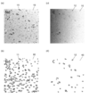
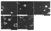
- mapping image by the Auger electron spectroscopy in the surface of the NdFeB type sintered magnet manufactured by the manufacturing method of the NdFeB type sintered magnet of a comparative example The mapping image by the Auger electron spectroscopy in the surface of the NdFeB type sintered magnet of a present Example.
- the concentration distribution of Tb was measured with respect to the distance (depth direction) from the coated surface on the cut surface perpendicular to the coated surface of Tb of the NdFeB-based sintered magnet of this example after the grain boundary diffusion treatment.
- Tb with respect to the distance (depth direction) from the coated surface of the NdFeB sintered magnet of the comparative example after the grain boundary diffusion treatment on the cut surface perpendicular to the coated surface of Tb during the grain boundary diffusion treatment The figure which shows the result of the line analysis which measured density
- the manufacturing method of the NdFeB-based sintered magnet of this example is a hydrogen crushing step (step) in which hydrogen is occluded by occluding hydrogen in a NdFeB-based alloy prepared in advance by a strip cast method.
- step A1 and NdFeB alloy that was not dehydrogenated after hydrogen cracking in the hydrogen cracking process was mixed with 0.05 to 0.1 wt% of a lubricant such as methyl caprylate, and nitrogen gas was used using a jet mill device.
- a fine pulverization step (step A2) in which the median particle size distribution (D 50 ) measured by laser diffraction method is 3.2 ⁇ m or less in an air stream, and 0.05 to 0.15 wt.
- step A3 in which a lubricant such as 1% methyl laurate is mixed and filled in the mold (filling container) at a density of 3.0 to 3.5 g / cm 3 , and the alloy powder in the mold is placed in a magnetic field at room temperature Alignment process (step A4) to align, and alignment A sintering step (step A5), the of sintering the alloy powder of the mold.
- the steps A3 to A5 are performed by a pressless process.
- steps A1 to A5 are performed consistently in an oxygen-free atmosphere.
- the method for producing the NdFeB-based sintered magnet of the comparative example includes dehydration for desorbing the hydrogen after the hydrogen is stored in the NdFeB-based alloy in the hydrogen crushing step (step B1). It is the same as the flowchart of FIG. 1 except that the element heating is performed and the temperature increasing alignment is performed in which the alloy powder is heated before, during, or during the alignment in the magnetic field in the alignment step (step B4). is there.
- the temperature-programmed orientation is a method for suppressing repulsion between particles after orientation by heating the alloy powder during the orientation step to reduce the coercivity of each particle of the alloy powder. By this method, the degree of orientation of the manufactured NdFeB-based sintered magnet can be improved.
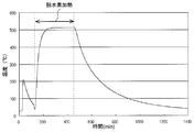
- FIG. 3 shows the temperature history of the hydrogen crushing step (step A1) in the method of manufacturing the NdFeB-based sintered magnet of this example
- FIG. 4 shows the hydrogen crushing step in the method of manufacturing the NdFeB-based sintered magnet of the comparative example ( It is a temperature history of step B1).
- FIG. 4 is a temperature history of a general hydrogen cracking process in which dehydrogenation heating is performed.
- hydrogen is occluded in the NdFeB alloy flakes. Since this hydrogen storage process is an exothermic reaction, the temperature of the NdFeB alloy rises to about 200-300 ° C. Then, it cools naturally to room temperature, carrying out vacuum deaeration. During this time, the hydrogen occluded in the alloy expands and a large number of cracks (cracks) are generated inside the alloy and are crushed. In this process, some of the hydrogen reacts with the alloy. In order to desorb the hydrogen that has reacted with this alloy, it is heated to about 500 ° C. and then naturally cooled to room temperature.
- the hydrogen crushing process can be completed in about 400 minutes even if the time for cooling to room temperature is reduced while vacuum degassing after the temperature rise due to heat generation. Therefore, compared with the example of FIG. 4, the manufacturing time can be shortened by about 1000 minutes (16.7 hours).
- the method of manufacturing the NdFeB-based sintered magnet of this embodiment it is possible to simplify the manufacturing process and significantly reduce the manufacturing time.
- Table 1 also shows the results of applying the manufacturing method of the NdFeB-based sintered magnet of this example and the manufacturing method of the NdFeB-based sintered magnet of the comparative example to the alloys having the composition numbers 1 to 4 shown in Table 1. It is shown in 2.
- the results in Table 2 are for the case where the particle size of the finely pulverized alloy powder is adjusted to be 2.82 ⁇ m by the laser diffraction method D 50 . Further, a Hosokawa Micron 100AFG type jet mill apparatus was used as the jet mill apparatus used in the fine pulverization step.
- a pulse magnetization measuring device (trade name: Pulse BH Curve Tracer PBH-1000) manufactured by Nippon Electromagnetic Instrument Co., Ltd.
- the degree of orientation B r / J s was almost the same as the manufacturing method of the comparative example in which the temperature rising alignment was performed and was 95% or more. Is obtained.
- the magnetic anisotropy of the alloy powder particles that is, the coercive force for each particle
- the coercive force of each particle was low, after the alloy powder is oriented, a reverse magnetic domain is generated in each particle with a decrease in the applied magnetic field, resulting in a multi-domain.
- a high degree of orientation can be obtained in the same manner as the temperature rising orientation without performing the temperature rising orientation, so that the manufacturing process is simplified and the manufacturing time is shortened. be able to.
- the sintering temperature shown in Table 2 indicates the temperature when the density of the sintered body is closest to the theoretical density of the NdFeB-based sintered magnet in each composition and each manufacturing method. As shown in Table 2, it was found that the sintering temperature tends to be lower in this example than in the comparative example. Lowering the sintering temperature leads to lower energy consumption when manufacturing the NdFeB-based sintered magnet, that is, energy saving (energy saving). In addition, there is an effect that the life of the mold heated together with the alloy powder is extended.
- the NdFeB-based sintered magnet manufactured by the manufacturing method of the present example has a higher coercive force H cJ than the NdFeB-based sintered magnet manufactured by the manufacturing method of the comparative example. I understood.
- Auger Electron Spectroscopy (AES ).
- the measuring apparatus is an Auger micro probe (trade name: JAMP-9500F) manufactured by JEOL Ltd.
- Auger electron spectroscopy is a technique for irradiating the surface of an object to be measured with an electron beam and measuring the energy distribution of Auger electrons generated by the interaction between the electrons and the electrons.
- Auger electrons have energy values that are unique to each element. Therefore, by measuring the energy distribution of Auger electrons, it exists on the surface of the object to be measured (more specifically, a depth of several nm from the surface).
- the element to be identified can be performed. Further, the element can be quantified (quantitative analysis) from the peak intensity ratio. Further, the element distribution in the depth direction of the object to be measured can be examined by performing ion sputtering (for example, sputtering with Ar ions) on the surface of the object to be measured.
- the actual analysis method is as follows. In order to remove the dirt on the sample surface, tilt the sample at an Ar sputtering angle (30 degrees with respect to the horizontal plane) and sputter the sample surface for 2 to 3 minutes before the actual measurement. Next, several Nd-rich phases in the grain boundary triple point where C and O can be detected are selected to obtain an Auger spectrum, and a detection threshold is determined based on this (ROI setting).
- the acquisition conditions were a voltage of 20 kV, a current of 2 ⁇ 10 ⁇ 8 A, and an angle of 55 degrees (relative to the horizontal plane). Subsequently, the main measurement is performed under the same conditions as described above, and Auger images for Nd and C are acquired.
- the surface 10 of the NdFeB sintered magnet manufactured by the manufacturing method of the present example and the comparative example is scanned for the alloy of composition number 2 in Table 1 to obtain the Auger images of Nd and C, respectively.
- Nd is present over almost the entire surface of the NdFeB-based sintered magnet (FIGS. 5A and 6A), but the region 11 has a concentration higher than the average value of the entire NdFeB-based sintered magnet by image processing.
- the C-rich region 12 was extracted from the images shown in FIGS. 5C and 6C (FIGS. 5D and 6D).
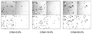
- the total area of the Nd-rich grain boundary triple point region 11 extracted as described above and the total area in the C-rich region 12 in the Nd-rich grain boundary triple point region 11 are obtained, and these are determined as the volume of both parts. And the ratio C / Nd between the two was calculated. The above was performed with multiple fields of view.
- the surfaces of the NdFeB-based sintered magnets of this example and comparative example corresponding to composition number 2 are divided into small areas of 24 ⁇ m ⁇ 24 ⁇ m, and the distribution of Nd and C in each small area and C / The results of analyzing Nd are shown respectively (Note that only three representative small regions are shown in FIGS. 7 and 8).
- a low C / Nd of 20% or less was obtained in almost all small regions.
- a distribution showing 50% C / Nd was seen in some subregions, but there was no subregion showing C / Nd above 50%.
- C / Nd in the entire region (region combining all the small regions) was 26.5%.
- the NdFeB-based sintered magnet of the comparative example a high C / Nd of 90% or more was obtained in almost all small regions.
- C / Nd of the entire region was 93.1%.
- NdFeB-based sintered magnet of this example an NdFeB-based sintered magnet in which the volume ratio of the C-rich region to the volume of the Nd-rich grain boundary triple point region is 50% or less.
- NdFeB-based sintered magnet of this example An NdFeB-based sintered magnet that does not have this feature is referred to as a “comparative NdFeB-based sintered magnet”.
- the carbon content in the NdFeB-based sintered magnet is almost the same value for each manufacturing method.
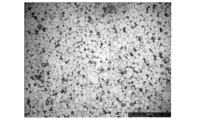
- the carbon content of the NdFeB sintered magnet corresponding to composition number 3 in Table 1 was measured with a CS-230 type carbon / sulfur analyzer manufactured by LECO. It was about 800 ppm by the manufacturing method of Further, micrographs of each of the above NdFeB-based sintered magnets manufactured by the manufacturing method of this example were taken from a plurality of fields of view (the optical micrograph of FIG. 9 is one of them), and an image analysis apparatus (Nireco Corporation) When the particle size distribution was measured with LUZEX® AP manufactured, the average particle size of the main phase particles was obtained in the range of 2.6 to 2.9 ⁇ m.
- Table 3 and Table 4 show the magnetic properties of the NdFeB-based sintered magnet of this example and the comparative NdFeB-based sintered magnet and the magnetic properties after being applied as a base material for the grain boundary diffusion method.
- the thickness direction is the direction of magnetization produced by the production method of this example for the alloys having composition numbers 1 to 4 having the characteristics (i) to (iii), respectively.
- This is a NdFeB-based sintered magnet with a length of 7 mm, a width of 7 mm, and a thickness of 3 mm.
- Comparative Examples 1 to 4 in Table 3 are the same as Examples 1 to 4 manufactured from the alloys having composition numbers 1 to 4 and having the characteristics (ii) and (iii), respectively, by the manufacturing method of the comparative example.
- NdFeB based sintered magnet of the same size are used as a base material for a grain boundary diffusion method described later.
- Br is the residual magnetic flux density (magnetization J or magnetic flux density B when the magnetic field H of the magnetization curve (JH curve) or demagnetization curve (BH curve) is 0)
- Js is the saturation magnetization.
- H cB is the coercivity defined by the demagnetization curve
- H cJ is the coercivity defined by the magnetization curve
- (BH) max is the maximum energy product (the magnetic flux density B in the demagnetization curve The maximum value of the product of the magnetic field H), B r / J s is the degree of orientation, and SQ is the squareness ratio. The larger these values are, the better magnet characteristics are obtained.
- the NdFeB-based sintered magnet of this example has a higher coercive force H cJ than the NdFeB-based sintered magnet of the comparative example.
- the degree of orientation B r / J s is almost the same, but the squareness ratio SQ of the NdFeB-based sintered magnet of this example is much higher than that of the comparative NdFeB-based sintered magnet. It has been.
- Table 4 shows the magnetic characteristics after performing the grain boundary diffusion treatment using each NdFeB-based sintered magnet of Table 3 as a base material and Tb as RH .
- the grain boundary diffusion (Grain Boundary Diffusion: GBD) process was performed as follows. First, a paste in which 0.07 g of silicone oil was added to 10 g of a mixture of TbNiAl alloy powder of Tb: 92 wt%, Ni: 4.3 wt%, Al: 3.7 wt% and silicone grease in a weight ratio of 80:20 was used. 10 mg each was applied to both magnetic pole faces (7 mm x 7 mm faces) of the material. Next, the cuboid base material coated with the paste is placed on a molybdenum tray provided with a plurality of point-shaped support portions, and the cuboid base material is supported by the support portions while being in a vacuum of 10 ⁇ 4 Pa. And heated. The heating temperature and heating time were 880 ° C. and 10 hours, respectively. Thereafter, it was rapidly cooled to near room temperature, then heated at 500 ° C. for 2 hours, and then rapidly cooled to room temperature.
- GBD grain boundary diffusion
- a magnet that has been subjected to grain boundary diffusion treatment using the NdFeB-based sintered magnet of this example as a base material is a magnet that has been subjected to grain boundary diffusion treatment using the NdFeB-based sintered magnet of a comparative example as a base material.
- the coercive force H cJ is greatly improved.
- the NdFeB-based sintered magnet of the comparative example is used as the base material
- the squareness ratio SQ is greatly reduced by the grain boundary diffusion treatment
- the NdFeB-based sintered magnet of this embodiment is used as the base material Then, the squareness ratio SQ hardly decreased, but rather increased.
- the decrease in the maximum energy product (BH) max due to the grain boundary diffusion treatment is 1.49 MGOe, 1.83 MGOe, 0.23 MGOe, and 0.77 MGOe for the substrates of Examples 1 to 4, respectively, while Comparative Example 1 For the substrates of ⁇ 4, they are 2.22MGOe, 1.44MGOe, 0.68MGOe, and 1.54MGOe, respectively. Comparing these numerical values, the NdFeB-based sintered magnet of Example 2 has a greater decrease in the maximum energy product after the grain boundary diffusion treatment than the NdFeB-based sintered magnet of Comparative Example 2 manufactured from the same starting alloy. ing.
- the NdFeB-based sintered magnet of this example is suppressed from lowering the maximum energy product than the NdFeB-based sintered magnet of the comparative example manufactured from the starting alloy having the same composition, The amount of decrease is nearly half of the amount of decrease in the comparative example.
- the NdFeB-based sintered magnet of this example is the maximum energy after the grain boundary diffusion treatment than the NdFeB-based sintered magnet of the comparative example. Reduction of product (BH) max is suppressed.
- the present inventor further provides the Tb concentration distribution in the grain boundaries of the NdFeB-based sintered magnet after the grain boundary diffusion treatment (hereinafter referred to as “GBD-treated magnet”), in particular, the grain boundary in this example and the comparative example.
- the Tb concentration distribution at the triple point and two grain boundaries was measured.
- FIGS. 10 and 11 show the GBD-treated magnets of this example and comparative example corresponding to composition number 2, respectively, with a peripheral blade cutting machine parallel to the magnetic pole surface at a depth of 1 mm from the magnetic pole surface (coated surface).
- FIG. 3 is a WDS map image obtained by polishing Tb from a WDS (wavelength dispersion) analysis of EPMA (manufactured by JEOL Ltd., JXA-8500F) after polishing the cut surface. The measurement was carried out using an acceleration voltage of 15 kV, WDS analysis, spectral crystal LIFH (TbL ⁇ ), and probe diameter based on the instrument resolution, and the EPMA X-ray count raw data was converted to Tb concentration.
- WDS wavelength dispersion
- TbL ⁇ spectral crystal LIFH
- the calibration curve used at that time was prepared by conducting a quantitative analysis between the vicinity of the Tb coated surface with the highest Tb concentration and the opposite side surface with the low Tb concentration.
- the Tb density is shown in black and white shading (the white one has a higher density).
- the difference between the highest Tb concentration at each grain boundary triple point and the lowest Tb concentration at the two grain boundary portion connected to the grain boundary triple point is calculated.
- the results shown in FIG. 12 were obtained for the GBD-treated magnets of the present example and the comparative example. From the histogram of FIG. 12, in the magnet after GBD processing of this example (result without the dehydrogenation step in FIG. 12), the Tb concentration difference between the grain boundary triple point and the two grain boundary part is 2 to 3 wt%. It was found that the ratio of grain boundary triple points exceeded 50%. It was also found that the ratio of the grain boundary triple point where the difference in Tb concentration between the grain boundary triple point and the two grain boundary part was 3 wt% or less exceeded 60%.
- the ratio of the grain boundary triple points where the Tb concentration difference between the grain boundary triple point and the two grain boundary part is 4 to 6 wt% From the viewpoint of the uniformity of the Tb concentration in the grain boundary, it was found to be inferior to the magnet after GBD treatment of this example.
- the inventor also measured the diffusion of Tb in the depth direction from the Tb-coated surface of the magnets after GBD treatment of the present example and the comparative example.
- a base material sintered body before grain boundary diffusion treatment
- Tb is applied to the non-oxidized magnetic pole face
- grain boundary diffusion is performed.
- cut the NdFeB sintered magnet after the grain boundary diffusion treatment magnet after GBD treatment
- Went. Perform line analysis from the Tb-coated surface to the opposite end under the same measurement conditions as above, and obtain 5 data at intervals that can be identified by the instrument resolution for one sample.
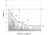
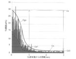
- a density graph in the depth direction of the Tb density was created by superimposing. For the conversion of the Tb concentration, the same method as that used when obtaining the images of FIGS. 10 and 11 was used. The results are shown in FIG. 13 and FIG.
- the spiked portion with high concentration indicates the Tb concentration in the grain boundary, and the other low concentration portion in the main phase particle. Tb concentrations are shown respectively.
- C gx in the figure is an approximation of the curve that touches the apex of each peak with an exponential decay curve, and represents the change in the concentration of Tb in the grain boundary with respect to the distance (depth) from the Tb coating surface.
- C x in the figure is an approximation of an exponential decay curve that is in contact with each point between the peaks, and represents the change in the concentration of Tb in the main phase particles with respect to the distance from the Tb coating surface.
- the Tb concentrations C gx and C x basically decrease as the distance from the coating surface increases. This decrease was more gradual in the magnet after GBD treatment of this example, and Tb diffused at a relatively high concentration of C gx of 5 wt% or more even at a depth of 3 mm (surface opposite to the coated surface). On the other hand, in the comparative GBD-treated magnet, the concentration Cgx of Tb in the grain boundary at a depth of 3 mm was 2 wt% or less.
- the difference C s -C d3 of the Tb concentration C gx in the grain boundary between the Tb coated surface (depth 0 mm) and the depth 3 mm from the Tb coated surface was 25 wt% or more in the comparative NdFeB sintered magnet. On the other hand, it was 20 wt% or less in the NdFeB-based sintered magnet of this example.
- the difference C s -C d1 of the Tb concentration C gx in the grain boundary at a depth of 1 mm from the Tb coated surface and the Tb coated surface was 20 wt% or more in the NdFeB sintered magnet of the comparative example. On the other hand, in the NdFeB system sintered magnet of this example, it was 15 wt% or less.
- the difference in the concentration of Tb in the main phase particles and in the grain boundaries is about 1 wt% of the NdFeB-based sintered magnet of the comparative example at the point of the depth of 3 mm where the concentration difference is the smallest, while the NdFeB of the present example It was over 3wt% for the sintered magnet.
- the amount of Tb (R H ) penetrating into the main phase particles in the vicinity of the coated surface is smaller and larger in the depth direction than the magnet after GBD treatment of the comparative example. You can see that it is spreading. Further, it can be seen from the magnitude of the difference between the C gx and C x curves in FIG.
- the GBD processed magnet of the present embodiment having the above features, whereas the concentration C x of Tb in the main phase grains during the Tb coated surface is about 7 wt%, about a GBD processed magnet of Comparative Example 12wt%.
- the GBD-treated magnet of this example has less Tb entering the main phase particles near the coated surface than the GBD-treated magnet of the comparative example.
- the decrease in the maximum energy product is suppressed compared to the magnet after GBD processing of the comparative example.
- the reason why the coercive force and the squareness ratio of the magnet after GBD treatment of this example are higher than that of the magnet after GBD treatment of the comparative example is considered to be because Tb is uniformly diffused in the grain boundaries.
- Tb can be diffused from one coated surface to a point with a depth of 3 mm.
- Tb can be diffused to the part.
- the increase in the coercive force of the post-treatment magnet from the state before grain boundary diffusion is shown.
- the increase in the coercive force of the magnet wins.
- the increase in coercive force at a thickness of 6 mm is almost the same as that at the thickness of 3 mm in the magnet after GBD processing of the present embodiment, but is greatly reduced in the magnet after GBD processing in the comparative example.
- a large increase in coercive force indicates that RH diffuses to the center of the magnet, and from this, the manufacturing method of the present example is thick after GBD treatment with high magnetic properties. It turns out that it is suitable for manufacture of a magnet.
Abstract
Description
プレス有り磁石製造方法では、圧縮成形体を作製するために大型のプレス機が必要となるため、密閉空間内で行うことが難しいのに対し、プレスなし磁石製造工程ではプレス機を用いないことから、密閉空間内で充填から焼結までの作業を行うことができるという特長がある。
また、磁石全体の粒界にRHを行き渡らせることができず、保磁力及び角型比を十分に高めることができなくなる。
NdFeB系合金の粉末を配向し、焼結することにより製造した基材の表面に付着させたDy及び/又はTb(RH)を、粒界拡散処理によって該基材内部の粒界に拡散させたNdFeB系焼結磁石であって、
RHを付着させた面に現れている粒界中のRHの濃度Cs(wt%)と、前記付着面から深さ3mmの粒界中のRHの濃度Cd3(wt%)との差Cs-Cd3が20wt%以下、
であることを特徴とする。
前記基材中の粒界三重点における希土類リッチ相の体積の総計に対する、該希土類リッチ相中の炭素リッチ相の体積の総計の比率が50%以下、
であることが望ましい。このような基材を用いることにより、粒界拡散処理の際にRHが炭素リッチ相に堰き止められることなく、上記のようにRHが粒界中を均等に拡散した構造を得ることができる。
なお、ステップA3~A5の工程はプレスなし工程により行われる。また、ステップA1~A5の工程は、一貫して無酸素雰囲気下で行われる。
なお、昇温配向とは、配向工程の際に合金粉末を加熱することにより、合金粉末の各粒子の保磁力を低下させ、配向後の粒子間の反発を抑える方法のことである。この方法により、製造後のNdFeB系焼結磁石の配向度を向上させることができる。
一方、本実施例のNdFeB系焼結磁石の製造方法では脱水素加熱を行わない。そのため、図3に示すように、発熱に伴う温度上昇後、真空脱気しつつ室温まで冷却させる時間を多少長めに取っても、約400分で水素解砕工程を終了することができる。従って、図4の例と比べると、約1000分(16.7時間)ほど製造時間を短縮することができる。
なお、表2の結果は、いずれも微粉砕後の合金粉末の粒径が、レーザ回折法のD50で2.82μmになるように調整した場合のものである。また、微粉砕工程に用いるジェットミル装置には、ホソカワミクロン製100AFG型ジェットミル装置を用いた。磁気特性の測定には、日本電磁測器株式会社製のパルス磁化測定装置(商品名:パルスBHカーブトレーサPBH-1000)を用いた。
また、表2の脱水素無し、昇温配向無しの結果が、本実施例のNdFeB系焼結磁石の製造方法を、脱水素有り、昇温配向有りの結果が、比較例のNdFeB系焼結磁石の製造方法を、それぞれ示している。


さらに、被測定物の表面をイオンスパッタ(例えばArイオンによるスパッタ)していくことで、被測定物の深さ方向の元素分布を調べることができる。
本実施例のNdFeB系焼結磁石では、殆どの小領域において、20%以下の低いC/Ndが得られた。一部の小領域で50%のC/Ndを示す分布が見られたが、50%を超えるC/Ndを示す小領域はなかった。また、領域全体(全ての小領域を合わせた領域)でのC/Ndは26.5%であった。
一方、比較例のNdFeB系焼結磁石では、ほぼ全ての小領域で90%以上という高いC/Ndが得られた。また、領域全体のC/Ndは93.1%であった。
表3の実施例1~4は、上記(i)~(iii)の特徴を有する、それぞれ組成番号1~4の合金に対して本実施例の製造方法により製造した、厚さ方向が磁化方向である縦7mm×横7mm×厚さ3mmのNdFeB系焼結磁石である。また、表3の比較例1~4は、上記(ii)及び(iii)の特徴を有さない、それぞれ組成番号1~4の合金から比較例の製造方法により製造した実施例1~4と同じ大きさのNdFeB系焼結磁石である。これら実施例1~4及び比較例1~4のNdFeB系焼結磁石は、後述する粒界拡散法の基材として使用される。


まず、Tb:92wt%、Ni:4.3wt%、Al:3.7wt%のTbNiAl合金粉末とシリコーングリースを重量比で80:20の割合で混合した混合物10gにシリコーンオイルを0.07g添加したペーストを基材の両磁極面(7mm×7mmの面)にそれぞれ10mgずつ塗布した。
次に、上記ペーストを塗布した直方体基材を、複数の尖形状の支持部が設けられたモリブデン製のトレイに載せ、直方体基材を該支持部によって支持しつつ、10-4Paの真空中で加熱した。加熱温度と加熱時間はそれぞれ880℃、10時間とした。その後室温付近まで急冷して、次に500℃で2時間加熱して、再度室温まで急冷した。
これらの数値を比較すると、実施例2のNdFeB系焼結磁石では、同じ出発合金から製造される比較例2のNdFeB系焼結磁石よりも粒界拡散処理後の最大エネルギー積の低下が大きくなっている。しかしながら、それ以外では、本実施例のNdFeB系焼結磁石の方が、同じ組成の出発合金から製造される比較例のNdFeB系焼結磁石よりも最大エネルギー積の低下が抑えられていると共に、その低下量は、比較例の低下量の半分近くになっている。
このように、同じ組成の出発合金に対しては、多くの場合、本実施例のNdFeB系焼結磁石の方が、比較例のNdFeB系焼結磁石よりも、粒界拡散処理後の最大エネルギー積(BH)maxの低下が抑えられる。

11…Ndリッチ相の存在する領域
12…Cが分布する領域
Claims (5)
- NdFeB系合金の粉末を配向し、焼結することにより製造した基材の表面に付着させたDy及び/又はTb(以下、「Dy及び/又はTb」を「RH」とする)を、粒界拡散処理によって該基材内部の粒界に拡散させたNdFeB系焼結磁石であって、
RHを付着させた面に現れている粒界中のRHの濃度Cs(wt%)と、前記付着面から深さ3mmの粒界中のRHの濃度Cd3(wt%)との差Cs-Cd3が20wt%以下、
であることを特徴とするNdFeB系焼結磁石。 - 前記付着面に現れている粒界中のRHの濃度Cs(wt%)と、前記付着面から深さ1mmの粒界中のRHの濃度Cd1(wt%)との差Cs-Cd1が15wt%以下、
であることを特徴とする請求項1に記載のNdFeB系焼結磁石。 - 前記基材中の粒界三重点における希土類リッチ相の体積の総計に対する、該希土類リッチ相中の炭素リッチ相の体積の総計の比率が50%以下、
であることを特徴とする請求項1又は2に記載のNdFeB系焼結磁石。 - 前記基材全体の炭素含有率が1000ppm以下であることを特徴とする請求項1~3のいずれかに記載のNdFeB系焼結磁石。
- 前記基材を構成する粒子である主相粒子の平均粒径が4.5μm以下であることを特徴とする請求項1~4のいずれかに記載のNdFeB系焼結磁石。
Priority Applications (5)
| Application Number | Priority Date | Filing Date | Title |
|---|---|---|---|
| US14/114,657 US10468166B2 (en) | 2011-12-27 | 2012-12-27 | NdFeB system sintered magnet |
| KR1020137023816A KR101485281B1 (ko) | 2011-12-27 | 2012-12-27 | NdFeB계 소결 자석 |
| JP2013536353A JP5503086B2 (ja) | 2011-12-27 | 2012-12-27 | NdFeB系焼結磁石 |
| CN201280021381.0A CN103797549B (zh) | 2011-12-27 | 2012-12-27 | NdFeB系烧结磁体 |
| EP12863318.7A EP2800108B1 (en) | 2011-12-27 | 2012-12-27 | Sintered neodymium magnet |
Applications Claiming Priority (4)
| Application Number | Priority Date | Filing Date | Title |
|---|---|---|---|
| JP2011286864 | 2011-12-27 | ||
| JP2011-286864 | 2011-12-27 | ||
| JP2012026719 | 2012-02-09 | ||
| JP2012-026719 | 2012-02-09 |
Publications (1)
| Publication Number | Publication Date |
|---|---|
| WO2013100010A1 true WO2013100010A1 (ja) | 2013-07-04 |
Family
ID=48697489
Family Applications (1)
| Application Number | Title | Priority Date | Filing Date |
|---|---|---|---|
| PCT/JP2012/083788 WO2013100010A1 (ja) | 2011-12-27 | 2012-12-27 | NdFeB系焼結磁石 |
Country Status (6)
| Country | Link |
|---|---|
| US (1) | US10468166B2 (ja) |
| EP (1) | EP2800108B1 (ja) |
| JP (1) | JP5503086B2 (ja) |
| KR (1) | KR101485281B1 (ja) |
| CN (1) | CN103797549B (ja) |
| WO (1) | WO2013100010A1 (ja) |
Cited By (5)
| Publication number | Priority date | Publication date | Assignee | Title |
|---|---|---|---|---|
| JP2017073465A (ja) * | 2015-10-07 | 2017-04-13 | Tdk株式会社 | R−t−b系焼結磁石 |
| US10290408B2 (en) * | 2011-12-27 | 2019-05-14 | Intermetallics Co., Ltd. | NdFeB system sintered magnet |
| US10468166B2 (en) | 2011-12-27 | 2019-11-05 | Intermetallics Co., Ltd. | NdFeB system sintered magnet |
| WO2021111921A1 (ja) | 2019-12-03 | 2021-06-10 | 信越化学工業株式会社 | 希土類焼結磁石 |
| EP3913644A1 (en) | 2020-05-19 | 2021-11-24 | Shin-Etsu Chemical Co., Ltd. | Rare earth sintered magnet and making method |
Families Citing this family (4)
| Publication number | Priority date | Publication date | Assignee | Title |
|---|---|---|---|---|
| WO2014017249A1 (ja) * | 2012-07-24 | 2014-01-30 | インターメタリックス株式会社 | NdFeB系焼結磁石の製造方法 |
| JP2015228431A (ja) * | 2014-06-02 | 2015-12-17 | インターメタリックス株式会社 | RFeB系磁石及びRFeB系磁石の製造方法 |
| US11328845B2 (en) | 2017-06-27 | 2022-05-10 | Daido Steel Co., Ltd. | RFeB-based magnet and method for producing RFeB-based magnet |
| US11527340B2 (en) | 2018-07-09 | 2022-12-13 | Daido Steel Co., Ltd. | RFeB-based sintered magnet |
Citations (5)
| Publication number | Priority date | Publication date | Assignee | Title |
|---|---|---|---|---|
| WO2006043348A1 (ja) | 2004-10-19 | 2006-04-27 | Shin-Etsu Chemical Co., Ltd. | 希土類永久磁石材料の製造方法 |
| WO2007088718A1 (ja) * | 2006-01-31 | 2007-08-09 | Hitachi Metals, Ltd. | R-Fe-B系希土類焼結磁石およびその製造方法 |
| WO2009004794A1 (ja) * | 2007-07-02 | 2009-01-08 | Hitachi Metals, Ltd. | R-Fe-B系希土類焼結磁石およびその製造方法 |
| WO2010109760A1 (ja) * | 2009-03-27 | 2010-09-30 | 株式会社日立製作所 | 焼結磁石及びそれを用いた回転電機 |
| WO2011004894A1 (ja) | 2009-07-10 | 2011-01-13 | インターメタリックス株式会社 | NdFeB焼結磁石及びその製造方法 |
Family Cites Families (21)
| Publication number | Priority date | Publication date | Assignee | Title |
|---|---|---|---|---|
| DE69318147T2 (de) | 1993-07-06 | 1998-11-12 | Sumitomo Spec Metals | R-Fe-B Dauermagnetmaterialien und ihre Herstellungsverfahren |
| JP2003297622A (ja) | 2002-03-28 | 2003-10-17 | Tdk Corp | 水素吸収方法、水素粉砕方法および希土類永久磁石の製造方法 |
| JP4215240B2 (ja) | 2003-02-26 | 2009-01-28 | Tdk株式会社 | 水素粉砕方法、希土類永久磁石の製造方法 |
| US7618497B2 (en) | 2003-06-30 | 2009-11-17 | Tdk Corporation | R-T-B based rare earth permanent magnet and method for production thereof |
| JP4702542B2 (ja) | 2005-12-02 | 2011-06-15 | 信越化学工業株式会社 | R−t−b−c型焼結磁石の製造方法 |
| US7988795B2 (en) | 2005-12-02 | 2011-08-02 | Shin-Etsu Chemical Co., Ltd. | R-T-B—C rare earth sintered magnet and making method |
| US7806991B2 (en) | 2005-12-22 | 2010-10-05 | Hitachi, Ltd. | Low loss magnet and magnetic circuit using the same |
| SG170075A1 (en) | 2006-03-03 | 2011-04-29 | Hitachi Metals Ltd | R-fe-b rare earth sintered magnet and method for producing same |
| JP4840606B2 (ja) | 2006-11-17 | 2011-12-21 | 信越化学工業株式会社 | 希土類永久磁石の製造方法 |
| JP4564993B2 (ja) | 2007-03-29 | 2010-10-20 | 株式会社日立製作所 | 希土類磁石及びその製造方法 |
| JP4900121B2 (ja) | 2007-03-29 | 2012-03-21 | 日立化成工業株式会社 | フッ化物コート膜形成処理液およびフッ化物コート膜形成方法 |
| US20080241513A1 (en) | 2007-03-29 | 2008-10-02 | Matahiro Komuro | Rare earth magnet and manufacturing method thereof |
| US20080241368A1 (en) | 2007-03-29 | 2008-10-02 | Matahiro Komuro | Treating solution for forming fluoride coating film and method for forming fluoride coating film |
| JP4998096B2 (ja) | 2007-06-06 | 2012-08-15 | 日立金属株式会社 | R−Fe−B系永久磁石の製造方法 |
| JP5328161B2 (ja) | 2008-01-11 | 2013-10-30 | インターメタリックス株式会社 | NdFeB焼結磁石の製造方法及びNdFeB焼結磁石 |
| CN104143402B (zh) | 2009-01-07 | 2017-05-24 | 大同特殊钢株式会社 | 磁各向异性磁体原材料 |
| CN102087917B (zh) | 2009-12-02 | 2014-06-25 | 北京中科三环高技术股份有限公司 | 一种辐射取向磁环或多极磁环的制备方法及其压制设备 |
| KR101201021B1 (ko) | 2010-03-31 | 2012-11-14 | 닛토덴코 가부시키가이샤 | 영구 자석 및 영구 자석의 제조 방법 |
| JP5870522B2 (ja) | 2010-07-14 | 2016-03-01 | トヨタ自動車株式会社 | 永久磁石の製造方法 |
| EP2800108B1 (en) | 2011-12-27 | 2018-04-11 | Intermetallics Co., Ltd. | Sintered neodymium magnet |
| CN106448984A (zh) | 2011-12-27 | 2017-02-22 | 因太金属株式会社 | NdFeB系烧结磁体 |
-
2012
- 2012-12-27 EP EP12863318.7A patent/EP2800108B1/en active Active
- 2012-12-27 US US14/114,657 patent/US10468166B2/en active Active
- 2012-12-27 JP JP2013536353A patent/JP5503086B2/ja active Active
- 2012-12-27 KR KR1020137023816A patent/KR101485281B1/ko active IP Right Grant
- 2012-12-27 CN CN201280021381.0A patent/CN103797549B/zh active Active
- 2012-12-27 WO PCT/JP2012/083788 patent/WO2013100010A1/ja active Application Filing
Patent Citations (5)
| Publication number | Priority date | Publication date | Assignee | Title |
|---|---|---|---|---|
| WO2006043348A1 (ja) | 2004-10-19 | 2006-04-27 | Shin-Etsu Chemical Co., Ltd. | 希土類永久磁石材料の製造方法 |
| WO2007088718A1 (ja) * | 2006-01-31 | 2007-08-09 | Hitachi Metals, Ltd. | R-Fe-B系希土類焼結磁石およびその製造方法 |
| WO2009004794A1 (ja) * | 2007-07-02 | 2009-01-08 | Hitachi Metals, Ltd. | R-Fe-B系希土類焼結磁石およびその製造方法 |
| WO2010109760A1 (ja) * | 2009-03-27 | 2010-09-30 | 株式会社日立製作所 | 焼結磁石及びそれを用いた回転電機 |
| WO2011004894A1 (ja) | 2009-07-10 | 2011-01-13 | インターメタリックス株式会社 | NdFeB焼結磁石及びその製造方法 |
Non-Patent Citations (1)
| Title |
|---|
| See also references of EP2800108A4 |
Cited By (5)
| Publication number | Priority date | Publication date | Assignee | Title |
|---|---|---|---|---|
| US10290408B2 (en) * | 2011-12-27 | 2019-05-14 | Intermetallics Co., Ltd. | NdFeB system sintered magnet |
| US10468166B2 (en) | 2011-12-27 | 2019-11-05 | Intermetallics Co., Ltd. | NdFeB system sintered magnet |
| JP2017073465A (ja) * | 2015-10-07 | 2017-04-13 | Tdk株式会社 | R−t−b系焼結磁石 |
| WO2021111921A1 (ja) | 2019-12-03 | 2021-06-10 | 信越化学工業株式会社 | 希土類焼結磁石 |
| EP3913644A1 (en) | 2020-05-19 | 2021-11-24 | Shin-Etsu Chemical Co., Ltd. | Rare earth sintered magnet and making method |
Also Published As
| Publication number | Publication date |
|---|---|
| KR101485281B1 (ko) | 2015-01-21 |
| KR20130130043A (ko) | 2013-11-29 |
| JP5503086B2 (ja) | 2014-05-28 |
| EP2800108A4 (en) | 2015-08-12 |
| CN103797549A (zh) | 2014-05-14 |
| CN103797549B (zh) | 2016-07-06 |
| US10468166B2 (en) | 2019-11-05 |
| EP2800108A1 (en) | 2014-11-05 |
| US20140062632A1 (en) | 2014-03-06 |
| JPWO2013100010A1 (ja) | 2015-05-11 |
| EP2800108B1 (en) | 2018-04-11 |
Similar Documents
| Publication | Publication Date | Title |
|---|---|---|
| JP5553461B2 (ja) | NdFeB系焼結磁石 | |
| JP5400255B1 (ja) | NdFeB系焼結磁石及び該NdFeB系焼結磁石の製造方法 | |
| JP5503086B2 (ja) | NdFeB系焼結磁石 | |
| EP2484464B1 (en) | Powder for magnetic member, powder compact, and magnetic member | |
| JP6221233B2 (ja) | R−t−b系焼結磁石およびその製造方法 | |
| JP5400256B1 (ja) | NdFeB系焼結磁石 | |
| WO2013146781A1 (ja) | NdFeB系焼結磁石 |
Legal Events
| Date | Code | Title | Description |
|---|---|---|---|
| ENP | Entry into the national phase |
Ref document number: 2013536353 Country of ref document: JP Kind code of ref document: A |
|
| 121 | Ep: the epo has been informed by wipo that ep was designated in this application |
Ref document number: 12863318 Country of ref document: EP Kind code of ref document: A1 |
|
| ENP | Entry into the national phase |
Ref document number: 20137023816 Country of ref document: KR Kind code of ref document: A |
|
| WWE | Wipo information: entry into national phase |
Ref document number: 14114657 Country of ref document: US |
|
| WWE | Wipo information: entry into national phase |
Ref document number: 2012863318 Country of ref document: EP |
|
| NENP | Non-entry into the national phase |
Ref country code: DE |