WO2013099542A1 - 車両の衝撃吸収部材 - Google Patents
車両の衝撃吸収部材 Download PDFInfo
- Publication number
- WO2013099542A1 WO2013099542A1 PCT/JP2012/081520 JP2012081520W WO2013099542A1 WO 2013099542 A1 WO2013099542 A1 WO 2013099542A1 JP 2012081520 W JP2012081520 W JP 2012081520W WO 2013099542 A1 WO2013099542 A1 WO 2013099542A1
- Authority
- WO
- WIPO (PCT)
- Prior art keywords
- wood
- frame
- absorbing member
- test
- impact
- Prior art date
- Legal status (The legal status is an assumption and is not a legal conclusion. Google has not performed a legal analysis and makes no representation as to the accuracy of the status listed.)
- Ceased
Links
Images


Classifications
-
- B—PERFORMING OPERATIONS; TRANSPORTING
- B60—VEHICLES IN GENERAL
- B60R—VEHICLES, VEHICLE FITTINGS, OR VEHICLE PARTS, NOT OTHERWISE PROVIDED FOR
- B60R19/00—Wheel guards; Radiator guards, e.g. grilles; Obstruction removers; Fittings damping bouncing force in collisions
- B60R19/02—Bumpers, i.e. impact receiving or absorbing members for protecting vehicles or fending off blows from other vehicles or objects
- B60R19/24—Arrangements for mounting bumpers on vehicles
- B60R19/26—Arrangements for mounting bumpers on vehicles comprising yieldable mounting means
- B60R19/34—Arrangements for mounting bumpers on vehicles comprising yieldable mounting means destroyed upon impact, e.g. one-shot type
-
- B—PERFORMING OPERATIONS; TRANSPORTING
- B60—VEHICLES IN GENERAL
- B60R—VEHICLES, VEHICLE FITTINGS, OR VEHICLE PARTS, NOT OTHERWISE PROVIDED FOR
- B60R19/00—Wheel guards; Radiator guards, e.g. grilles; Obstruction removers; Fittings damping bouncing force in collisions
- B60R19/02—Bumpers, i.e. impact receiving or absorbing members for protecting vehicles or fending off blows from other vehicles or objects
- B60R19/03—Bumpers, i.e. impact receiving or absorbing members for protecting vehicles or fending off blows from other vehicles or objects characterised by material, e.g. composite
-
- F—MECHANICAL ENGINEERING; LIGHTING; HEATING; WEAPONS; BLASTING
- F16—ENGINEERING ELEMENTS AND UNITS; GENERAL MEASURES FOR PRODUCING AND MAINTAINING EFFECTIVE FUNCTIONING OF MACHINES OR INSTALLATIONS; THERMAL INSULATION IN GENERAL
- F16F—SPRINGS; SHOCK-ABSORBERS; MEANS FOR DAMPING VIBRATION
- F16F7/00—Vibration-dampers; Shock-absorbers
- F16F7/12—Vibration-dampers; Shock-absorbers using plastic deformation of members
Definitions
- the present invention relates to a shock absorbing member for a vehicle, and more specifically, includes a columnar timber and a metal hollow cylindrical frame covering a side surface of the timber, and the impact of the vehicle that receives a compressive load due to the shock in the axial direction.
- the present invention relates to an absorbent member.
- an impact absorbing member that includes columnar wood and a metal hollow cylindrical frame that covers the side surface of the wood, and that receives a compressive load due to impact in the axial direction.
- the frame is a regular rectangular tube, and the ratio of the frame to the thickness of one side outside the hollow square cross section is 9-12.
- a frame is a regular N square cylinder shape or regular cylinder shape which satisfy
- fills N> 5.
- the frame is an elliptic cylinder, and the ratio a / b of the major axis a to the minor axis b inside the hollow elliptical cross section of the frame is 3 or less.
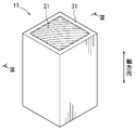
- FIG. 3 is a perspective view of an impact absorbing member according to Embodiment 1.
- FIG. It is sectional drawing orthogonal to the axial direction of the impact-absorbing member shown in FIG.
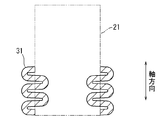
- FIG. 3 is a schematic diagram showing a deformation mode of the frame of the shock absorbing member shown in FIG. 1 cut at a position corresponding to the line III-III in the same figure, and the ratio to the thickness of the outer side of the hollow square section according to the first embodiment. Shows the case of 9-12.
- FIG. 5 is a schematic diagram showing a deformation mode of a frame body of an impact absorbing member in which a ratio with respect to a thickness of an outer side of a hollow square cross section is out of 9-12.
- 6 is a perspective view of an impact absorbing member according to Embodiment 2.
- FIG. 6 is a perspective view of an impact absorbing member according to Embodiment 3.
- FIG. 6 is a perspective view of an impact absorbing member according to Embodiment 4.
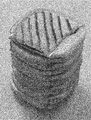
- FIG. It is sectional drawing orthogonal to the axial direction of the impact-absorbing member shown in FIG. It is a graph which shows the relationship between the displacement obtained by Test 1, and the compressive load about the cedar timber. No. in Table 1 It is a graph which shows the relationship between the displacement obtained by the test 2, and the compressive load about 1 sample. No. in Table 1 It is the photograph of the external appearance which looked at the sample of 1 from the diagonal direction after compression of the test 2.
- FIG. No. in Table 1 It is a graph which shows the relationship between the displacement obtained by Test 2, and a compressive load about 2 samples. No.
- Table 1 It is the photograph of the external appearance which looked at the sample of 2 from the diagonal direction after compression of the test 2.
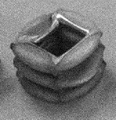
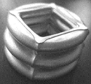
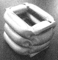
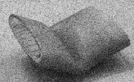
- FIG. It is the photograph of the external appearance which looked at the frame A of Table 2 from the diagonal direction after compression of the test 3.
- FIG. It is the photograph of the external appearance which looked at the frame B of Table 2 from the diagonal direction after compression of the test 3.
- FIG. It is the photograph of the external appearance which looked at the frame C of Table 2 from the diagonal direction after compression of the test 3.
- FIG. It is the photograph of the external appearance which looked at the frame D of Table 2 from the diagonal direction after compression of the test 3.
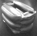
- FIG. It is the photograph of the external appearance which looked at the frame K of Table 3 from the diagonal direction after compression of Test 4.
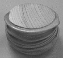
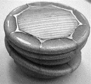
- FIG. No. in Table 5 3 is a photograph of the appearance of a sample of No. 3 viewed from an oblique direction after compression in Test 6.
- FIG. No. in Table 5 4 is a photograph of the appearance of a sample of 4 viewed from an oblique direction after compression in Test 6.
- FIG. No. in Table 5 5 is a photograph of the appearance of a sample of No. 5 viewed from an oblique direction after compression in Test 6.
- FIG. No. in Table 5 5 is a photograph of the appearance of a sample of No. 5 viewed from an oblique direction after compression in Test 6.
- Table 5 5 is a graph showing the relationship between the displacement obtained by Test 6 and the compressive load with respect to 5 samples.
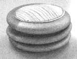
- No. in Table 5 It is the photograph of the external appearance which looked at the sample of 6 from the diagonal direction after compression of the test 6.
- FIG. No. in Table 5 7 is a photograph of an external appearance of the sample No. 7 viewed from an oblique direction during the compression of Test 6.
- FIG. No. in Table 5 8 is a photograph of the appearance of 8 samples viewed from an oblique direction after compression in Test 6.
- No. in Table 6 It is the photograph of the external appearance which looked at 11 samples from the diagonal direction after compression of the test 7.
- FIG. No. in Table 6 It is the photograph of the external appearance which looked at 12 samples from the diagonal direction after compression of test 7.
- the impact absorbing member is a member that is installed in a vehicle such as an automobile and absorbs impact energy at the time of collision.
- the installation location of the impact absorbing member in the vehicle is not particularly limited as long as it is a location where collision energy should be absorbed in order to protect passengers, pedestrians, and the like.
- the shock absorbing member 11 of the present embodiment includes a square columnar timber 21 having a square cross section orthogonal to the axial direction (hereinafter simply referred to as a cross section) and a metal frame that covers the side surface of the timber 21. It consists of a body 31. It is installed so that the impact at the time of collision can be received in the axial direction of the quadrangular prism.
- the wood 21 is made into a square column shape so that the fiber direction is parallel to the compression load (axial direction).
- the kind of wood 21 is not specifically limited, For example, conifers, such as a cedar, a cypress, and a pine, and broad-leaved trees, such as a zelkova and a beech, can be used.
- a wood having a large specific gravity is excellent in strength, and a wood having a small specific gravity has a high porosity, so that the amount of deformation due to compression is large. Considering this point, it is desirable to select wood having an appropriate specific gravity according to the installation position of the vehicle.
- wood having a specific gravity of 0.2 to 0.4 because the amount of impact energy absorbed can be further increased by having a certain degree of strength while ensuring a sufficient amount of deformation due to compression.
- Examples of the wood having a specific gravity of 0.2 to 0.4 include cedar, hinoki and pine.
- the frame body 31 is a regular square cylinder, that is, a hollow cylinder whose cross section perpendicular to the axial direction (hereinafter simply referred to as a cross section) is a hollow square.
- the frame 31 can support the wood 21 and can be deformed together with the wood 21 by receiving an axial compressive load.
- the frame 31 is made of a metal such as aluminum, copper, or iron.
- the frame 31 is fitted to the outside of the wood 21 without a gap, and covers the entire side surface (outer peripheral surface) of the wood 21 without excess or deficiency.
- the thickness T of the frame 31 is substantially uniform, and the ratio L / T (hereinafter referred to as a side-to-thickness ratio) of the side L to the thickness T of the outside of the hollow square cross section of the frame 31 is 9. Within the range of -12.
- the impact absorbing member 11 is installed so that the axial direction (fiber direction) of the wood 21 and the collision direction of the vehicle are parallel to each other.
- the frame body 31 surrounding the wood 21 is crushed in the axial direction while buckling, and the wood 21 is prevented from falling by the frame body 31 and is axially moved. It is compressed and deformed as it is.
- the principle is not necessarily clear, but the frame body 31 is buckled and deformed while repeatedly bulging only outward as schematically shown in FIG. 3A.
- the frame body 31 surrounding the wood 21 is crushed without changing the axial direction, so that the wood 21 is straightly compressed and deformed along the fiber direction without falling down. To do. At that time, the frame 31 is not entrapped inside but is crushed while bulging outside, so that it is difficult to bite into the wood 21 and the original features of the wood can be utilized to the maximum. Further, when the frame body bites into the wood, the wood easily breaks due to the tilting of the fibers, and the deformation behavior thereof is different each time. However, according to the impact absorbing member of the present embodiment, since the frame body 31 does not easily bite into the wood 21, it is possible to suppress the variation in the deformation behavior of the wood and to achieve a predictable level.
- the shock absorbing member 11 of the present embodiment is crushed without the frame body 31 entering the inside as described above, so the frame body 31 is made of wood even if there is no gap between the frame body 31 and the wood 21. It is difficult to bite into 21.
- a gap may be formed between the frame body 31 and the wood 21, and the shape of the wood 21 may not necessarily be a regular quadrangular prism shape.
- the wood 21 is inscribed in the frame 31 because the positioning of the wood 21 with respect to the frame 31 is easy. Further, it is more preferable that the wood 21 is fitted in the frame 31 without any gap, because the strength of the shock absorbing member 11 can be efficiently increased with respect to the area of the cross section, and the shock absorption amount can be increased efficiently.
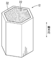
- the shock absorbing member 12 of the present embodiment includes a regular N-gonal columnar wood 22 having a cross-section of N ⁇ 5, and a metal frame 32 that covers the side surface of the wood 22. It receives the compressive load due to impact in the axial direction.
- the materials of the wood 22 and the frame 32 are the same as those of the wood 21 and the frame 31 of the first embodiment, and only the shapes are different.
- the frame body 32 is a regular N square cylinder having N equal to the wood 22, that is, a hollow cylinder having a hollow regular N square cross section.
- the frame 32 can support the timber 22 and can be deformed together with the timber 22 by receiving an axial compressive load. Is covered without excess or deficiency.
- the thickness of the frame body 32 is uniform and is appropriately set within a range that can be deformed together with the wood 22, and the balance with the outer dimensions of the wood 23 is not particularly specified.
- the shock absorbing member 12 When a compressive load in the axial direction acts on the shock absorbing member 12, the principle is not necessarily clear, but the frame 32 is crushed in the axial direction while repeatedly bulging outward only. At the same time, the wood 22 is prevented from falling by the frame body 32 and is compressed and deformed in the axial direction as it is. According to the shock absorbing member 12, when an axial compressive load is applied, the frame 32 surrounding the wood 21 is crushed without changing the axial direction, so that the wood 22 does not fall down and is directly compressed and deformed along the fiber direction. To do. At that time, the frame body 32 does not enter the inside and is crushed while expanding outside, so that it is difficult to bite into the wood 22 and the original features of the wood can be utilized to the maximum. Further, since the frame body 32 and the wood 22 are unlikely to interfere with each other, variations in the deformation behavior of the wood can be suppressed. Further, variation in the reaction force can be suppressed, and variation in shock absorbing performance can be reduced.
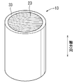
- the impact absorbing member 13 of the present embodiment includes a columnar wood 23 having a regular circular cross section and a metal frame 33 covering the side surface of the wood 23, and compresses a compressive load caused by the impact. It will be received in the direction.
- the materials of the wood 23 and the frame 33 are the same as those of the wood 21 and the frame 31 of the first embodiment, and only the shapes are different.
- the frame body 33 has a regular cylindrical shape, that is, a hollow cylindrical shape having a hollow regular circular cross section.
- the frame 33 can support the wood 23 and can be deformed together with the wood 23 by receiving an axial compressive load.
- the frame 33 fits on the outside of the wood 23 without a gap, and the entire side surface of the wood 23. Is covered without excess or deficiency.
- the thickness of the frame 33 is uniform and is appropriately set within a range that can be deformed together with the wood 23, and the balance with the outer dimensions of the wood 23 is not particularly specified.
- the frame 33 surrounding the wood 23 is squeezed in the axial direction while repeatedly bulging outward only.
- the timber 23 is prevented from falling by the frame 33 and is compressed and deformed in the axial direction as it is.
- the shock absorbing member 13 when an axial compressive load is applied, the frame 33 surrounding the wood 23 is crushed without changing the axial direction, so that the wood 23 is straightly compressed and deformed along the fiber direction without falling down. To do.
- the frame body 33 is not bent inward but is crushed while bending outward, so that it is difficult to bite into the wood 23 and the original features of the wood can be utilized to the maximum.
- the frame 33 and the wood 23 are unlikely to interfere with each other, variation in the deformation behavior of the wood can be suppressed. Further, variation in the reaction force can be suppressed, and variation in shock absorbing performance can be reduced.
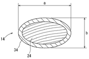
- the shock absorbing member 14 of the present embodiment includes a columnar wood 24 having an elliptical cross section and a metal frame 34 that covers the side surface of the wood 24, and compresses a compressive load caused by the impact in the axial direction. It is intended for The materials of the wood 24 and the frame 34 are the same as those of the wood 21 and the frame 31 of the first embodiment, and only the shapes are different.
- the frame body 34 has an elliptic cylindrical shape, that is, a hollow cylindrical shape having a hollow elliptical cross section.
- the ratio a / b of the major axis to the minor axis inside the hollow elliptical cross section of the frame 34 (hereinafter referred to as the ratio of major axis to minor axis) is 3 or less (see FIG. 7).
- the ratio of the major axis to minor axis a / b is equal to 1, the cross-sectional shape is a hollow circular shape, and therefore exactly 1 ⁇ a / b ⁇ 3.
- the frame 34 can support the wood 24 and can be deformed together with the wood 23 by receiving an axial compressive load. Is covered without excess or deficiency.
- the thickness of the frame 34 is uniform, and is set as appropriate within a range that can be deformed together with the wood 24.
- the principle of the frame 34 surrounding the wood 24 is not necessarily clear, but it is crushed in the axial direction while repeatedly inflating only to the outside, and at the same time the wood 24 is compressed. Deform. At this time, the frame body 34 is not folded inward but is crushed while being bent outward, so that it is difficult to bite into the wood 24 and the original features of the wood are precisely exhibited. In addition, since the frame body 34 and the wood 24 are unlikely to interfere with each other, variations in the deformation behavior of the wood can be suppressed. Further, variation in the reaction force can be suppressed, and variation in shock absorbing performance can be reduced.
- Test 1 aimed to confirm the original shock absorbing performance of wood.
- a cedar square (40 mm x 40 mm x axial length 70 mm) with a square cross-section is prepared so that the fiber direction is parallel to the axial direction (compression direction), and the frame is not externally fitted
- the result is shown in FIG.
- Test 2 In Test 2, according to the above-mentioned Embodiment 1, a hollow cylindrical frame was fitted to the outside of a wood having a square cross-sectional shape. Samples of 1 and 2 impact absorbing members were prepared. A cedar square was used as the wood, and an extruded product of aluminum (A5052) was used as the frame. The dimensions of each sample are shown in Table 1. In addition, the outer side L and the frame thickness T of the hollow square cross section in Table 1 correspond to L and T shown in FIG.
- Test 3 Therefore, in Test 3, a sample consisting only of a hollow cylindrical frame having a square cross-sectional shape in the axial direction was prepared, compressed in the same manner as in Test 1 above, and observed for deformation.
- FIGS. 13 to 16 show photographs of the sample after compression.
- a frame of A to D obtained by extrusion molding of aluminum (A5052) was used as a sample.
- the outer side L of the hollow square cross section was 20 mm, and the axial length was 70 mm. Only the thickness is different.
- the dimensions of each frame are shown in Table 2, and the form of compression deformation is also shown.
- Table 2 the No. of Test 2 is shown for the form of compression deformation. In the case where the sample was crushed while being bent inwardly or outwardly as in the case of the sample of No. 1, it was “unsuitable”. When it was crushed while expanding only outward as in the sample of 2, it was marked as “good”.
- Test 4 In Test 4, as in Test 3, a hollow cylindrical frame having a square cross-sectional shape in the axial direction was used as a sample, compressed in the same manner as in Test 3, and the deformation was observed. In this test 4, frames E to K having different outer side L and axial length as shown in Table 3 were used for the test. In Test 4, aluminum (A6063) was extruded to obtain each sample. Similar to Test 3, the form of compression deformation is also shown in Table 3.
- FIG. 17 representatively shows a state after compression of the frame body K with a photograph.
- Test 5 In Test 5, a hollow cylindrical frame having a hollow rectangular cross section shown in Table 4 was used as a sample, compressed in the same manner as in Tests 3 and 4, and the deformation was observed. The results are also shown in Table 4 as in Tests 3 and 4. In Test 5, aluminum (A6063) was extruded to obtain each sample.
- the outer short side and the outer long side shown in Table 4 are the length of the outer short side and the long side, respectively, of the hollow rectangular cross section.
- Test 6 In Test 6, according to Embodiment 3 or 4 above, a hollow cylindrical frame was fitted on the outside of a wood having a circular cross-sectional shape in the axial direction. Samples of 3 to 8 impact absorbing members were prepared. Cedar lumber was used as the wood, and an aluminum (A5052) extruded product was used as the frame. The dimensions of each sample are shown in Table 5. In addition, the major axis a and the minor axis b in Table 5 correspond to a and b shown in FIG. Then, No. Each sample of 3 to 8 was compressed in the same manner as in Test 2 above, and the deformation was observed. 20 to 25 show photographs of the state of each sample after compression. Further, the form of compression deformation is also shown in Table 5. In Table 5, “good” is indicated when the material is crushed while only bulging outward, and a comment is attached in other cases.
- the cross-sectional shape is a polygonal shape.
- Samples of 9 to 12 impact absorbing members were prepared.
- Cedar lumber was used as the wood, and an aluminum (A5052) extruded product was used as the frame.
- Table 6 shows the shape and dimensions of each sample. Then, No.
- Each of the samples 9 to 12 was compressed in the same manner as in Test 7 above, and the deformation was observed. The form of compression deformation is also shown in Table 6. In Table 6, when it is crushed while expanding only outside, it is described as “good”.
Landscapes
- Engineering & Computer Science (AREA)
- Mechanical Engineering (AREA)
- General Engineering & Computer Science (AREA)
- Body Structure For Vehicles (AREA)
- Vibration Dampers (AREA)
- Rod-Shaped Construction Members (AREA)
Priority Applications (2)
| Application Number | Priority Date | Filing Date | Title |
|---|---|---|---|
| US14/368,482 US9221413B2 (en) | 2011-12-26 | 2012-12-05 | Vehicle impact-absorbing member |
| EP12862992.0A EP2799289B1 (en) | 2011-12-26 | 2012-12-05 | Vehicle shock absorption member |
Applications Claiming Priority (2)
| Application Number | Priority Date | Filing Date | Title |
|---|---|---|---|
| JP2011-283389 | 2011-12-26 | ||
| JP2011283389A JP5776537B2 (ja) | 2011-12-26 | 2011-12-26 | 車両の衝撃吸収部材 |
Publications (1)
| Publication Number | Publication Date |
|---|---|
| WO2013099542A1 true WO2013099542A1 (ja) | 2013-07-04 |
Family
ID=48697039
Family Applications (1)
| Application Number | Title | Priority Date | Filing Date |
|---|---|---|---|
| PCT/JP2012/081520 Ceased WO2013099542A1 (ja) | 2011-12-26 | 2012-12-05 | 車両の衝撃吸収部材 |
Country Status (4)
| Country | Link |
|---|---|
| US (1) | US9221413B2 (https=) |
| EP (1) | EP2799289B1 (https=) |
| JP (1) | JP5776537B2 (https=) |
| WO (1) | WO2013099542A1 (https=) |
Families Citing this family (12)
| Publication number | Priority date | Publication date | Assignee | Title |
|---|---|---|---|---|
| EP2786903B1 (en) * | 2011-11-29 | 2018-03-14 | Toyota Shatai Kabushiki Kaisha | Shock-absorbing member for vehicle |
| JP5791676B2 (ja) * | 2013-09-10 | 2015-10-07 | 富士重工業株式会社 | 衝撃吸収装置 |
| JP6393921B2 (ja) * | 2013-11-20 | 2018-09-26 | 藤森工業株式会社 | 粘着剤組成物及び表面保護フィルム |
| JP6560568B2 (ja) * | 2015-09-07 | 2019-08-14 | 株式会社Subaru | エネルギ吸収構造体 |
| JP6558316B2 (ja) * | 2016-07-05 | 2019-08-14 | 株式会社豊田自動織機 | 荷重エネルギ吸収材 |
| JP6798457B2 (ja) * | 2017-09-15 | 2020-12-09 | トヨタ自動車株式会社 | バンパリインフォースメント |
| JP6863219B2 (ja) * | 2017-10-13 | 2021-04-21 | トヨタ自動車株式会社 | 車両側部構造 |
| JP6796244B2 (ja) * | 2017-11-15 | 2020-12-09 | トヨタ車体株式会社 | 車両の衝撃吸収部材 |
| JP2019217850A (ja) | 2018-06-18 | 2019-12-26 | トヨタ自動車株式会社 | 車両側部構造 |
| WO2020053623A1 (en) | 2018-09-11 | 2020-03-19 | Arcelormittal | Energy absorbing device, motor vehicle body and method for manufacturing thereof |
| JP7125826B2 (ja) * | 2019-02-18 | 2022-08-25 | トヨタ車体株式会社 | 衝撃吸収部材及びその製造方法 |
| JP7556822B2 (ja) * | 2021-04-27 | 2024-09-26 | 株式会社豊田中央研究所 | 衝撃吸収機構、衝撃吸収機構の製作方法 |
Citations (4)
| Publication number | Priority date | Publication date | Assignee | Title |
|---|---|---|---|---|
| JPS5818853U (ja) * | 1981-07-30 | 1983-02-05 | 三菱自動車工業株式会社 | 自動車のバンパ取付構造 |
| JP2001182769A (ja) | 1999-12-27 | 2001-07-06 | Showa Alum Corp | 衝撃吸収部材 |
| JP2004322733A (ja) * | 2003-04-22 | 2004-11-18 | Mitsubishi Alum Co Ltd | 車体のエネルギー吸収構造 |
| WO2005037518A1 (ja) * | 2003-10-17 | 2005-04-28 | Shiina Kasei Co. | プラスチック発泡複合体の製造方法 |
Family Cites Families (7)
| Publication number | Priority date | Publication date | Assignee | Title |
|---|---|---|---|---|
| JPS5818853A (ja) | 1981-07-24 | 1983-02-03 | Hitachi Ltd | 荷電粒子応用装置 |
| JP5545259B2 (ja) * | 2010-12-01 | 2014-07-09 | トヨタ車体株式会社 | 衝撃吸収部材 |
| JP2012218712A (ja) * | 2011-04-14 | 2012-11-12 | Toyota Auto Body Co Ltd | 衝撃吸収部材 |
| JP5522114B2 (ja) * | 2011-04-26 | 2014-06-18 | トヨタ車体株式会社 | 衝撃吸収部材 |
| WO2013036606A1 (en) * | 2011-09-06 | 2013-03-14 | Dl Manufacturing | Loading dock bumper assembly |
| EP2786903B1 (en) * | 2011-11-29 | 2018-03-14 | Toyota Shatai Kabushiki Kaisha | Shock-absorbing member for vehicle |
| US9403649B2 (en) * | 2013-03-12 | 2016-08-02 | Dl Manufacturing | Loading dock bumper assembly |
-
2011
- 2011-12-26 JP JP2011283389A patent/JP5776537B2/ja active Active
-
2012
- 2012-12-05 US US14/368,482 patent/US9221413B2/en active Active
- 2012-12-05 EP EP12862992.0A patent/EP2799289B1/en active Active
- 2012-12-05 WO PCT/JP2012/081520 patent/WO2013099542A1/ja not_active Ceased
Patent Citations (4)
| Publication number | Priority date | Publication date | Assignee | Title |
|---|---|---|---|---|
| JPS5818853U (ja) * | 1981-07-30 | 1983-02-05 | 三菱自動車工業株式会社 | 自動車のバンパ取付構造 |
| JP2001182769A (ja) | 1999-12-27 | 2001-07-06 | Showa Alum Corp | 衝撃吸収部材 |
| JP2004322733A (ja) * | 2003-04-22 | 2004-11-18 | Mitsubishi Alum Co Ltd | 車体のエネルギー吸収構造 |
| WO2005037518A1 (ja) * | 2003-10-17 | 2005-04-28 | Shiina Kasei Co. | プラスチック発泡複合体の製造方法 |
Also Published As
| Publication number | Publication date |
|---|---|
| EP2799289A4 (en) | 2015-08-05 |
| EP2799289B1 (en) | 2018-08-08 |
| JP2013132943A (ja) | 2013-07-08 |
| US20140346789A1 (en) | 2014-11-27 |
| US9221413B2 (en) | 2015-12-29 |
| EP2799289A1 (en) | 2014-11-05 |
| JP5776537B2 (ja) | 2015-09-09 |
Similar Documents
| Publication | Publication Date | Title |
|---|---|---|
| JP5776537B2 (ja) | 車両の衝撃吸収部材 | |
| WO2013080863A1 (ja) | 車両の衝撃吸収部材 | |
| US7651155B2 (en) | Progressive energy absorber | |
| JP5261490B2 (ja) | 衝撃吸収部材 | |
| EP1892159A2 (en) | Corrugated tubular energy absorbing structure. | |
| US20070181393A1 (en) | Impact absorbing device of vehicle | |
| JPWO2007029362A1 (ja) | 車両用衝撃吸収部材 | |
| WO2012073680A1 (ja) | 衝撃吸収部材 | |
| JP2013132943A5 (https=) | ||
| JP6191521B2 (ja) | 車両の衝撃吸収構造 | |
| JP5776522B2 (ja) | 車両の衝撃吸収部材 | |
| JP5729275B2 (ja) | 車両の衝撃吸収部材 | |
| JP5729274B2 (ja) | 車両の衝撃吸収構造 | |
| JP2001124128A (ja) | 衝撃吸収用多角形中空材 | |
| JP5056191B2 (ja) | エネルギ吸収部材 | |
| WO2013105438A1 (ja) | 車両の衝撃吸収構造 | |
| JP5522191B2 (ja) | 車両の衝撃吸収構造 | |
| JP2006176093A (ja) | バンパ及び車両の衝撃吸収構造 | |
| JPH06144133A (ja) | 金属製バンパー | |
| JP2006118550A (ja) | ハニカム材料 | |
| JP3099824B2 (ja) | 2つの衝撃吸収体を車体の構造部材に固定する構造及び衝撃吸収部品 | |
| JPH0893820A (ja) | 衝撃吸収構造体 | |
| JP2005162027A (ja) | 車両用エネルギ吸収構造 | |
| JP2005075256A (ja) | 鉄道車両用衝撃吸収構造体 | |
| JP2015044571A (ja) | アンダーランプロテクタ用ステイ部材及びその連結構造 |
Legal Events
| Date | Code | Title | Description |
|---|---|---|---|
| 121 | Ep: the epo has been informed by wipo that ep was designated in this application |
Ref document number: 12862992 Country of ref document: EP Kind code of ref document: A1 |
|
| WWE | Wipo information: entry into national phase |
Ref document number: 14368482 Country of ref document: US |
|
| NENP | Non-entry into the national phase |
Ref country code: DE |
|
| WWE | Wipo information: entry into national phase |
Ref document number: 2012862992 Country of ref document: EP |