WO2013099542A1 - Vehicle shock absorption member - Google Patents
Vehicle shock absorption member Download PDFInfo
- Publication number
- WO2013099542A1 WO2013099542A1 PCT/JP2012/081520 JP2012081520W WO2013099542A1 WO 2013099542 A1 WO2013099542 A1 WO 2013099542A1 JP 2012081520 W JP2012081520 W JP 2012081520W WO 2013099542 A1 WO2013099542 A1 WO 2013099542A1
- Authority
- WO
- WIPO (PCT)
- Prior art keywords
- wood
- frame
- absorbing member
- test
- frame body
- Prior art date
Links
Images


Classifications
-
- B—PERFORMING OPERATIONS; TRANSPORTING
- B60—VEHICLES IN GENERAL
- B60R—VEHICLES, VEHICLE FITTINGS, OR VEHICLE PARTS, NOT OTHERWISE PROVIDED FOR
- B60R19/00—Wheel guards; Radiator guards, e.g. grilles; Obstruction removers; Fittings damping bouncing force in collisions
- B60R19/02—Bumpers, i.e. impact receiving or absorbing members for protecting vehicles or fending off blows from other vehicles or objects
- B60R19/24—Arrangements for mounting bumpers on vehicles
- B60R19/26—Arrangements for mounting bumpers on vehicles comprising yieldable mounting means
- B60R19/34—Arrangements for mounting bumpers on vehicles comprising yieldable mounting means destroyed upon impact, e.g. one-shot type
-
- B—PERFORMING OPERATIONS; TRANSPORTING
- B60—VEHICLES IN GENERAL
- B60R—VEHICLES, VEHICLE FITTINGS, OR VEHICLE PARTS, NOT OTHERWISE PROVIDED FOR
- B60R19/00—Wheel guards; Radiator guards, e.g. grilles; Obstruction removers; Fittings damping bouncing force in collisions
- B60R19/02—Bumpers, i.e. impact receiving or absorbing members for protecting vehicles or fending off blows from other vehicles or objects
- B60R19/03—Bumpers, i.e. impact receiving or absorbing members for protecting vehicles or fending off blows from other vehicles or objects characterised by material, e.g. composite
-
- F—MECHANICAL ENGINEERING; LIGHTING; HEATING; WEAPONS; BLASTING
- F16—ENGINEERING ELEMENTS AND UNITS; GENERAL MEASURES FOR PRODUCING AND MAINTAINING EFFECTIVE FUNCTIONING OF MACHINES OR INSTALLATIONS; THERMAL INSULATION IN GENERAL
- F16F—SPRINGS; SHOCK-ABSORBERS; MEANS FOR DAMPING VIBRATION
- F16F7/00—Vibration-dampers; Shock-absorbers
- F16F7/12—Vibration-dampers; Shock-absorbers using plastic deformation of members
Definitions
- the present invention relates to a shock absorbing member for a vehicle, and more specifically, includes a columnar timber and a metal hollow cylindrical frame covering a side surface of the timber, and the impact of the vehicle that receives a compressive load due to the shock in the axial direction.
- the present invention relates to an absorbent member.
- an impact absorbing member that includes columnar wood and a metal hollow cylindrical frame that covers the side surface of the wood, and that receives a compressive load due to impact in the axial direction.
- the frame is a regular rectangular tube, and the ratio of the frame to the thickness of one side outside the hollow square cross section is 9-12.
- a frame is a regular N square cylinder shape or regular cylinder shape which satisfy
- fills N> 5.
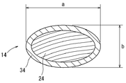
- the frame is an elliptic cylinder, and the ratio a / b of the major axis a to the minor axis b inside the hollow elliptical cross section of the frame is 3 or less.
- FIG. 3 is a perspective view of an impact absorbing member according to Embodiment 1.
- FIG. It is sectional drawing orthogonal to the axial direction of the impact-absorbing member shown in FIG.
- FIG. 3 is a schematic diagram showing a deformation mode of the frame of the shock absorbing member shown in FIG. 1 cut at a position corresponding to the line III-III in the same figure, and the ratio to the thickness of the outer side of the hollow square section according to the first embodiment. Shows the case of 9-12.
- FIG. 5 is a schematic diagram showing a deformation mode of a frame body of an impact absorbing member in which a ratio with respect to a thickness of an outer side of a hollow square cross section is out of 9-12.
- 6 is a perspective view of an impact absorbing member according to Embodiment 2.
- FIG. 6 is a perspective view of an impact absorbing member according to Embodiment 3.
- FIG. 6 is a perspective view of an impact absorbing member according to Embodiment 4.
- FIG. It is sectional drawing orthogonal to the axial direction of the impact-absorbing member shown in FIG. It is a graph which shows the relationship between the displacement obtained by Test 1, and the compressive load about the cedar timber. No. in Table 1 It is a graph which shows the relationship between the displacement obtained by the test 2, and the compressive load about 1 sample. No. in Table 1 It is the photograph of the external appearance which looked at the sample of 1 from the diagonal direction after compression of the test 2.
- FIG. No. in Table 1 It is a graph which shows the relationship between the displacement obtained by Test 2, and a compressive load about 2 samples. No.
- Table 1 It is the photograph of the external appearance which looked at the sample of 2 from the diagonal direction after compression of the test 2.
- FIG. It is the photograph of the external appearance which looked at the frame A of Table 2 from the diagonal direction after compression of the test 3.
- FIG. It is the photograph of the external appearance which looked at the frame B of Table 2 from the diagonal direction after compression of the test 3.
- FIG. It is the photograph of the external appearance which looked at the frame C of Table 2 from the diagonal direction after compression of the test 3.
- FIG. It is the photograph of the external appearance which looked at the frame D of Table 2 from the diagonal direction after compression of the test 3.
- FIG. It is the photograph of the external appearance which looked at the frame K of Table 3 from the diagonal direction after compression of Test 4.
- FIG. No. in Table 5 3 is a photograph of the appearance of a sample of No. 3 viewed from an oblique direction after compression in Test 6.
- FIG. No. in Table 5 4 is a photograph of the appearance of a sample of 4 viewed from an oblique direction after compression in Test 6.
- FIG. No. in Table 5 5 is a photograph of the appearance of a sample of No. 5 viewed from an oblique direction after compression in Test 6.
- FIG. No. in Table 5 5 is a photograph of the appearance of a sample of No. 5 viewed from an oblique direction after compression in Test 6.
- Table 5 5 is a graph showing the relationship between the displacement obtained by Test 6 and the compressive load with respect to 5 samples.
- No. in Table 5 It is the photograph of the external appearance which looked at the sample of 6 from the diagonal direction after compression of the test 6.
- FIG. No. in Table 5 7 is a photograph of an external appearance of the sample No. 7 viewed from an oblique direction during the compression of Test 6.
- FIG. No. in Table 5 8 is a photograph of the appearance of 8 samples viewed from an oblique direction after compression in Test 6.
- No. in Table 6 It is the photograph of the external appearance which looked at 11 samples from the diagonal direction after compression of the test 7.
- FIG. No. in Table 6 It is the photograph of the external appearance which looked at 12 samples from the diagonal direction after compression of test 7.
- the impact absorbing member is a member that is installed in a vehicle such as an automobile and absorbs impact energy at the time of collision.
- the installation location of the impact absorbing member in the vehicle is not particularly limited as long as it is a location where collision energy should be absorbed in order to protect passengers, pedestrians, and the like.
- the shock absorbing member 11 of the present embodiment includes a square columnar timber 21 having a square cross section orthogonal to the axial direction (hereinafter simply referred to as a cross section) and a metal frame that covers the side surface of the timber 21. It consists of a body 31. It is installed so that the impact at the time of collision can be received in the axial direction of the quadrangular prism.
- the wood 21 is made into a square column shape so that the fiber direction is parallel to the compression load (axial direction).
- the kind of wood 21 is not specifically limited, For example, conifers, such as a cedar, a cypress, and a pine, and broad-leaved trees, such as a zelkova and a beech, can be used.
- a wood having a large specific gravity is excellent in strength, and a wood having a small specific gravity has a high porosity, so that the amount of deformation due to compression is large. Considering this point, it is desirable to select wood having an appropriate specific gravity according to the installation position of the vehicle.
- wood having a specific gravity of 0.2 to 0.4 because the amount of impact energy absorbed can be further increased by having a certain degree of strength while ensuring a sufficient amount of deformation due to compression.
- Examples of the wood having a specific gravity of 0.2 to 0.4 include cedar, hinoki and pine.
- the frame body 31 is a regular square cylinder, that is, a hollow cylinder whose cross section perpendicular to the axial direction (hereinafter simply referred to as a cross section) is a hollow square.
- the frame 31 can support the wood 21 and can be deformed together with the wood 21 by receiving an axial compressive load.
- the frame 31 is made of a metal such as aluminum, copper, or iron.
- the frame 31 is fitted to the outside of the wood 21 without a gap, and covers the entire side surface (outer peripheral surface) of the wood 21 without excess or deficiency.
- the thickness T of the frame 31 is substantially uniform, and the ratio L / T (hereinafter referred to as a side-to-thickness ratio) of the side L to the thickness T of the outside of the hollow square cross section of the frame 31 is 9. Within the range of -12.
- the impact absorbing member 11 is installed so that the axial direction (fiber direction) of the wood 21 and the collision direction of the vehicle are parallel to each other.
- the frame body 31 surrounding the wood 21 is crushed in the axial direction while buckling, and the wood 21 is prevented from falling by the frame body 31 and is axially moved. It is compressed and deformed as it is.
- the principle is not necessarily clear, but the frame body 31 is buckled and deformed while repeatedly bulging only outward as schematically shown in FIG. 3A.
- the frame body 31 surrounding the wood 21 is crushed without changing the axial direction, so that the wood 21 is straightly compressed and deformed along the fiber direction without falling down. To do. At that time, the frame 31 is not entrapped inside but is crushed while bulging outside, so that it is difficult to bite into the wood 21 and the original features of the wood can be utilized to the maximum. Further, when the frame body bites into the wood, the wood easily breaks due to the tilting of the fibers, and the deformation behavior thereof is different each time. However, according to the impact absorbing member of the present embodiment, since the frame body 31 does not easily bite into the wood 21, it is possible to suppress the variation in the deformation behavior of the wood and to achieve a predictable level.
- the shock absorbing member 11 of the present embodiment is crushed without the frame body 31 entering the inside as described above, so the frame body 31 is made of wood even if there is no gap between the frame body 31 and the wood 21. It is difficult to bite into 21.
- a gap may be formed between the frame body 31 and the wood 21, and the shape of the wood 21 may not necessarily be a regular quadrangular prism shape.
- the wood 21 is inscribed in the frame 31 because the positioning of the wood 21 with respect to the frame 31 is easy. Further, it is more preferable that the wood 21 is fitted in the frame 31 without any gap, because the strength of the shock absorbing member 11 can be efficiently increased with respect to the area of the cross section, and the shock absorption amount can be increased efficiently.
- the shock absorbing member 12 of the present embodiment includes a regular N-gonal columnar wood 22 having a cross-section of N ⁇ 5, and a metal frame 32 that covers the side surface of the wood 22. It receives the compressive load due to impact in the axial direction.
- the materials of the wood 22 and the frame 32 are the same as those of the wood 21 and the frame 31 of the first embodiment, and only the shapes are different.
- the frame body 32 is a regular N square cylinder having N equal to the wood 22, that is, a hollow cylinder having a hollow regular N square cross section.
- the frame 32 can support the timber 22 and can be deformed together with the timber 22 by receiving an axial compressive load. Is covered without excess or deficiency.
- the thickness of the frame body 32 is uniform and is appropriately set within a range that can be deformed together with the wood 22, and the balance with the outer dimensions of the wood 23 is not particularly specified.
- the shock absorbing member 12 When a compressive load in the axial direction acts on the shock absorbing member 12, the principle is not necessarily clear, but the frame 32 is crushed in the axial direction while repeatedly bulging outward only. At the same time, the wood 22 is prevented from falling by the frame body 32 and is compressed and deformed in the axial direction as it is. According to the shock absorbing member 12, when an axial compressive load is applied, the frame 32 surrounding the wood 21 is crushed without changing the axial direction, so that the wood 22 does not fall down and is directly compressed and deformed along the fiber direction. To do. At that time, the frame body 32 does not enter the inside and is crushed while expanding outside, so that it is difficult to bite into the wood 22 and the original features of the wood can be utilized to the maximum. Further, since the frame body 32 and the wood 22 are unlikely to interfere with each other, variations in the deformation behavior of the wood can be suppressed. Further, variation in the reaction force can be suppressed, and variation in shock absorbing performance can be reduced.
- the impact absorbing member 13 of the present embodiment includes a columnar wood 23 having a regular circular cross section and a metal frame 33 covering the side surface of the wood 23, and compresses a compressive load caused by the impact. It will be received in the direction.
- the materials of the wood 23 and the frame 33 are the same as those of the wood 21 and the frame 31 of the first embodiment, and only the shapes are different.
- the frame body 33 has a regular cylindrical shape, that is, a hollow cylindrical shape having a hollow regular circular cross section.
- the frame 33 can support the wood 23 and can be deformed together with the wood 23 by receiving an axial compressive load.
- the frame 33 fits on the outside of the wood 23 without a gap, and the entire side surface of the wood 23. Is covered without excess or deficiency.
- the thickness of the frame 33 is uniform and is appropriately set within a range that can be deformed together with the wood 23, and the balance with the outer dimensions of the wood 23 is not particularly specified.
- the frame 33 surrounding the wood 23 is squeezed in the axial direction while repeatedly bulging outward only.
- the timber 23 is prevented from falling by the frame 33 and is compressed and deformed in the axial direction as it is.
- the shock absorbing member 13 when an axial compressive load is applied, the frame 33 surrounding the wood 23 is crushed without changing the axial direction, so that the wood 23 is straightly compressed and deformed along the fiber direction without falling down. To do.
- the frame body 33 is not bent inward but is crushed while bending outward, so that it is difficult to bite into the wood 23 and the original features of the wood can be utilized to the maximum.
- the frame 33 and the wood 23 are unlikely to interfere with each other, variation in the deformation behavior of the wood can be suppressed. Further, variation in the reaction force can be suppressed, and variation in shock absorbing performance can be reduced.
- the shock absorbing member 14 of the present embodiment includes a columnar wood 24 having an elliptical cross section and a metal frame 34 that covers the side surface of the wood 24, and compresses a compressive load caused by the impact in the axial direction. It is intended for The materials of the wood 24 and the frame 34 are the same as those of the wood 21 and the frame 31 of the first embodiment, and only the shapes are different.
- the frame body 34 has an elliptic cylindrical shape, that is, a hollow cylindrical shape having a hollow elliptical cross section.
- the ratio a / b of the major axis to the minor axis inside the hollow elliptical cross section of the frame 34 (hereinafter referred to as the ratio of major axis to minor axis) is 3 or less (see FIG. 7).
- the ratio of the major axis to minor axis a / b is equal to 1, the cross-sectional shape is a hollow circular shape, and therefore exactly 1 ⁇ a / b ⁇ 3.
- the frame 34 can support the wood 24 and can be deformed together with the wood 23 by receiving an axial compressive load. Is covered without excess or deficiency.
- the thickness of the frame 34 is uniform, and is set as appropriate within a range that can be deformed together with the wood 24.
- the principle of the frame 34 surrounding the wood 24 is not necessarily clear, but it is crushed in the axial direction while repeatedly inflating only to the outside, and at the same time the wood 24 is compressed. Deform. At this time, the frame body 34 is not folded inward but is crushed while being bent outward, so that it is difficult to bite into the wood 24 and the original features of the wood are precisely exhibited. In addition, since the frame body 34 and the wood 24 are unlikely to interfere with each other, variations in the deformation behavior of the wood can be suppressed. Further, variation in the reaction force can be suppressed, and variation in shock absorbing performance can be reduced.
- Test 1 aimed to confirm the original shock absorbing performance of wood.
- a cedar square (40 mm x 40 mm x axial length 70 mm) with a square cross-section is prepared so that the fiber direction is parallel to the axial direction (compression direction), and the frame is not externally fitted
- the result is shown in FIG.
- Test 2 In Test 2, according to the above-mentioned Embodiment 1, a hollow cylindrical frame was fitted to the outside of a wood having a square cross-sectional shape. Samples of 1 and 2 impact absorbing members were prepared. A cedar square was used as the wood, and an extruded product of aluminum (A5052) was used as the frame. The dimensions of each sample are shown in Table 1. In addition, the outer side L and the frame thickness T of the hollow square cross section in Table 1 correspond to L and T shown in FIG.
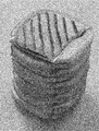
- Test 3 Therefore, in Test 3, a sample consisting only of a hollow cylindrical frame having a square cross-sectional shape in the axial direction was prepared, compressed in the same manner as in Test 1 above, and observed for deformation.
- FIGS. 13 to 16 show photographs of the sample after compression.
- a frame of A to D obtained by extrusion molding of aluminum (A5052) was used as a sample.
- the outer side L of the hollow square cross section was 20 mm, and the axial length was 70 mm. Only the thickness is different.
- the dimensions of each frame are shown in Table 2, and the form of compression deformation is also shown.
- Table 2 the No. of Test 2 is shown for the form of compression deformation. In the case where the sample was crushed while being bent inwardly or outwardly as in the case of the sample of No. 1, it was “unsuitable”. When it was crushed while expanding only outward as in the sample of 2, it was marked as “good”.
- Test 4 In Test 4, as in Test 3, a hollow cylindrical frame having a square cross-sectional shape in the axial direction was used as a sample, compressed in the same manner as in Test 3, and the deformation was observed. In this test 4, frames E to K having different outer side L and axial length as shown in Table 3 were used for the test. In Test 4, aluminum (A6063) was extruded to obtain each sample. Similar to Test 3, the form of compression deformation is also shown in Table 3.
- FIG. 17 representatively shows a state after compression of the frame body K with a photograph.
- Test 5 In Test 5, a hollow cylindrical frame having a hollow rectangular cross section shown in Table 4 was used as a sample, compressed in the same manner as in Tests 3 and 4, and the deformation was observed. The results are also shown in Table 4 as in Tests 3 and 4. In Test 5, aluminum (A6063) was extruded to obtain each sample.
- the outer short side and the outer long side shown in Table 4 are the length of the outer short side and the long side, respectively, of the hollow rectangular cross section.
- Test 6 In Test 6, according to Embodiment 3 or 4 above, a hollow cylindrical frame was fitted on the outside of a wood having a circular cross-sectional shape in the axial direction. Samples of 3 to 8 impact absorbing members were prepared. Cedar lumber was used as the wood, and an aluminum (A5052) extruded product was used as the frame. The dimensions of each sample are shown in Table 5. In addition, the major axis a and the minor axis b in Table 5 correspond to a and b shown in FIG. Then, No. Each sample of 3 to 8 was compressed in the same manner as in Test 2 above, and the deformation was observed. 20 to 25 show photographs of the state of each sample after compression. Further, the form of compression deformation is also shown in Table 5. In Table 5, “good” is indicated when the material is crushed while only bulging outward, and a comment is attached in other cases.
- the cross-sectional shape is a polygonal shape.
- Samples of 9 to 12 impact absorbing members were prepared.
- Cedar lumber was used as the wood, and an aluminum (A5052) extruded product was used as the frame.
- Table 6 shows the shape and dimensions of each sample. Then, No.
- Each of the samples 9 to 12 was compressed in the same manner as in Test 7 above, and the deformation was observed. The form of compression deformation is also shown in Table 6. In Table 6, when it is crushed while expanding only outside, it is described as “good”.
Landscapes
- Engineering & Computer Science (AREA)
- Mechanical Engineering (AREA)
- General Engineering & Computer Science (AREA)
- Body Structure For Vehicles (AREA)
- Vibration Dampers (AREA)
- Rod-Shaped Construction Members (AREA)
Abstract
Provided is a shock absorption member (11), comprising a columnar wood material (21), and a metallic hollow tube-shaped frame body (31) which covers the lateral faces of the wood material, with which a compression load from a shock is received in the axial direction. According to one aspect, the frame body (31) is a square tube-shaped body, and the proportion to the thickness of one outer side of a hollow square cross-section of the frame body (31) is 9-12.
Description
本発明は、車両の衝撃吸収部材に関し、詳しくは、柱状の木材と、該木材の側面を覆う金属製の中空筒状の枠体とを備え、衝撃による圧縮荷重を軸方向に受ける車両の衝撃吸収部材に関する。
The present invention relates to a shock absorbing member for a vehicle, and more specifically, includes a columnar timber and a metal hollow cylindrical frame covering a side surface of the timber, and the impact of the vehicle that receives a compressive load due to the shock in the axial direction. The present invention relates to an absorbent member.
この種の車両の衝撃吸収部材は、例えば、特開2001-182769号公報(以下文献という)に開示されている。この文献の衝撃吸収部材では、アルミニウム製中空材からなる枠体に木材が略ぴったりとあるいは若干きつく嵌め込まれている。具体的には、軸方向に直交する断面が40mm角の中空正方形、軸方向長さが120mm、厚みが2mmである枠体に木材が嵌装されている。この文献では、このような枠体に木材を嵌め込むことにより衝撃を受けて衝撃吸収部材が変位するのに伴う反力の変動を抑制することができるとされている。更に、木材の繊維方向を枠体の軸方向に一致させることで、衝撃エネルギーの吸収量の増加が図られている。
This type of vehicle impact absorbing member is disclosed in, for example, Japanese Patent Application Laid-Open No. 2001-182769 (hereinafter referred to as literature). In the impact absorbing member of this document, wood is fitted almost exactly or slightly tightly into a frame made of an aluminum hollow material. Specifically, wood is fitted to a frame having a hollow square having a cross section perpendicular to the axial direction of 40 mm square, an axial length of 120 mm, and a thickness of 2 mm. In this document, it is said that by fitting wood into such a frame body, it is possible to suppress fluctuations in the reaction force caused by the impact absorbing member being displaced upon receiving an impact. Furthermore, the amount of impact energy absorbed is increased by making the fiber direction of the wood coincide with the axial direction of the frame.
上記の文献に記載された実施形態に従って作製した衝撃吸収部材を軸方向に圧縮してみると、枠体が内側と外側とに交互に大きく折れ曲がりながら蛇腹状に座屈変形した。そして、内側に折れ曲がった枠体が木材に食い込むことで、局所的に木材の繊維の変形方向が傾斜していた。木材は本来多孔質であるとともに繊維が一方向に揃っている。このため、繊維方向を圧縮方向に一致させ、繊維方向に真っ直ぐに木材を圧縮することができれば、木材を枠体に嵌装する単純な構造にて木材の本来の特徴を最大限に活かし衝撃エネルギーの吸収量を向上させることができるはずである。
When the shock absorbing member produced according to the embodiment described in the above-mentioned literature was compressed in the axial direction, the frame body buckled and deformed in a bellows-like shape while being bent largely alternately on the inside and outside. And the deformation | transformation direction of the fiber of wood locally inclined because the frame body bent inward bites into wood. Wood is inherently porous and fibers are aligned in one direction. For this reason, if the fiber direction is matched with the compression direction and the wood can be compressed straight in the fiber direction, the impact energy can be maximized by utilizing the original characteristics of the wood with a simple structure in which the wood is fitted into the frame. It should be possible to improve the amount of absorption.
本発明のひとつの観点によると、柱状の木材と、この木材の側面を覆う金属製の中空筒状の枠体とを備え、衝撃による圧縮荷重を軸方向に受ける衝撃吸収部材が提供される。ひとつの態様では、枠体は正四角筒状であり、この枠体の中空正方形断面の外側の一辺の厚みに対する比が9~12である。また、別の態様では、枠体はN≧5を満たす正N角筒状又は正円筒状である。さらに別の態様では、枠体は楕円筒状であり、この枠体の中空楕円断面の内側の長径aの短径bに対する比a/bが3以下である。
According to one aspect of the present invention, there is provided an impact absorbing member that includes columnar wood and a metal hollow cylindrical frame that covers the side surface of the wood, and that receives a compressive load due to impact in the axial direction. In one embodiment, the frame is a regular rectangular tube, and the ratio of the frame to the thickness of one side outside the hollow square cross section is 9-12. Moreover, in another aspect, a frame is a regular N square cylinder shape or regular cylinder shape which satisfy | fills N> = 5. In yet another aspect, the frame is an elliptic cylinder, and the ratio a / b of the major axis a to the minor axis b inside the hollow elliptical cross section of the frame is 3 or less.
衝撃吸収部材は、自動車等の車両に設置されて衝突時の衝撃エネルギーを吸収するための部材である。車両における衝撃吸収部材の設置場所は、乗員や歩行者等を保護するために衝突エネルギーを吸収すべき場所であれば特に限定されない。例えば、フェンダパネルとボディパネルとの間、バンパリインホースとサイドメンバとの間、ドアパネルとドアトリムとの間、ピラーとピラートリムとの間、天井パネルとルーフライナとの間、フロアパネルとカーペットとの間などに設置することができる。以下、本発明の実施の形態について図面を参照しながら具体的に説明する。
The impact absorbing member is a member that is installed in a vehicle such as an automobile and absorbs impact energy at the time of collision. The installation location of the impact absorbing member in the vehicle is not particularly limited as long as it is a location where collision energy should be absorbed in order to protect passengers, pedestrians, and the like. For example, between fender panels and body panels, between bumper in hoses and side members, between door panels and door trims, between pillars and pillar trims, between ceiling panels and roof liners, between floor panels and carpets. It can be installed in between. Hereinafter, embodiments of the present invention will be specifically described with reference to the drawings.
[実施形態1]
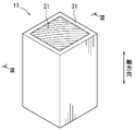
本実施形態の衝撃吸収部材11は、図1に示すように、軸方向に直交する断面(以下、単に断面という)が正方形の四角柱状の木材21と、木材21の側面を覆う金属製の枠体31とからなる。衝突時の衝撃を四角柱の軸方向に受けることができるように設置されるものである。 [Embodiment 1]
As shown in FIG. 1, theshock absorbing member 11 of the present embodiment includes a square columnar timber 21 having a square cross section orthogonal to the axial direction (hereinafter simply referred to as a cross section) and a metal frame that covers the side surface of the timber 21. It consists of a body 31. It is installed so that the impact at the time of collision can be received in the axial direction of the quadrangular prism.
本実施形態の衝撃吸収部材11は、図1に示すように、軸方向に直交する断面(以下、単に断面という)が正方形の四角柱状の木材21と、木材21の側面を覆う金属製の枠体31とからなる。衝突時の衝撃を四角柱の軸方向に受けることができるように設置されるものである。 [Embodiment 1]
As shown in FIG. 1, the
木材21は、その繊維方向が圧縮荷重(軸方向)と平行になるように四角柱状に製材されている。木材21の種類は特に限定されず、例えば、スギ、ヒノキ、マツ等の針葉樹や、ケヤキやブナ等の広葉樹を用いることができる。比重が大きい木材は強度に優れ、比重が小さい木材は気孔率が高いため、圧縮による変形量が大きくなる特徴がある。この点を考慮し、車両の設置位置に合わせて適宜の比重の木材を選択するのが望ましい。比重が0.2~0.4の木材を用いると、圧縮による変形量を十分に確保しつつ、ある程度の強度を有することで、衝撃エネルギーの吸収量をより高めることができ好ましい。比重が0.2~0.4の木材としては、例えば、スギ、ヒノキ、マツ等が挙げられる。
The wood 21 is made into a square column shape so that the fiber direction is parallel to the compression load (axial direction). The kind of wood 21 is not specifically limited, For example, conifers, such as a cedar, a cypress, and a pine, and broad-leaved trees, such as a zelkova and a beech, can be used. A wood having a large specific gravity is excellent in strength, and a wood having a small specific gravity has a high porosity, so that the amount of deformation due to compression is large. Considering this point, it is desirable to select wood having an appropriate specific gravity according to the installation position of the vehicle. It is preferable to use wood having a specific gravity of 0.2 to 0.4 because the amount of impact energy absorbed can be further increased by having a certain degree of strength while ensuring a sufficient amount of deformation due to compression. Examples of the wood having a specific gravity of 0.2 to 0.4 include cedar, hinoki and pine.
枠体31は、正四角筒状、すなわち軸方向に直交する断面(以下、単に断面という)が中空正方形であるような中空筒状である。枠体31は、木材21を支持することができるとともに、軸方向の圧縮荷重を受けて木材21とともに変形することのできるものであり、例えば、アルミニウムや銅、鉄などの金属からなる。枠体31は、木材21の外側に隙間無く嵌っており、木材21の側面(外周面)全体を過不足無く覆っている。
The frame body 31 is a regular square cylinder, that is, a hollow cylinder whose cross section perpendicular to the axial direction (hereinafter simply referred to as a cross section) is a hollow square. The frame 31 can support the wood 21 and can be deformed together with the wood 21 by receiving an axial compressive load. For example, the frame 31 is made of a metal such as aluminum, copper, or iron. The frame 31 is fitted to the outside of the wood 21 without a gap, and covers the entire side surface (outer peripheral surface) of the wood 21 without excess or deficiency.
図2に示すように、枠体31の厚みTはほぼ均一であり、枠体31の中空正方形断面の外側の一辺Lの厚みTに対する比L/T(以下、一辺対厚み比という)が9~12の範囲内である。
As shown in FIG. 2, the thickness T of the frame 31 is substantially uniform, and the ratio L / T (hereinafter referred to as a side-to-thickness ratio) of the side L to the thickness T of the outside of the hollow square cross section of the frame 31 is 9. Within the range of -12.
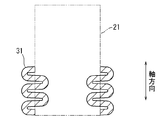
衝撃吸収部材11は、木材21の軸方向(繊維方向)と車両の衝突方向とが平行になるように設置される。衝突に伴って衝撃吸収部材11に軸方向の圧縮荷重が作用すると、木材21を囲う枠体31は座屈しながら軸方向に押し潰され、木材21は枠体31により転倒が抑制されて軸方向にそのまま圧縮変形する。このとき、その原理は必ずしも明らかではないが、枠体31は、図3Aに模式的に示すように、外側にのみ繰り返し膨らみながら座屈変形する。かかる衝撃吸収部材11によれば、軸方向の圧縮荷重が作用すると、木材21を囲う枠体31が軸方向を変えることなく潰れるため、木材21が転倒することなく繊維方向に沿って真っ直ぐ圧縮変形する。その際、枠体31が、内側には入り込まずに外側に膨らみながら潰れるため、木材21に食い込みにくく、木材本来の特徴を最大限に活かすことができる。また、枠体が木材に食い込む場合、木材は繊維が傾倒させられることで割れやすく、その変形挙動はそのたび毎に異なる。しかし、本実施形態の衝撃吸収部材によれば、木材21に枠体31が食い込みにくいことで、木材の変形挙動のばらつきを抑えて、予測可能な程度とすることができる。さらに、枠体の食い込みにより木材の繊維が部分的に傾倒することによる反力の変動を引き起こしにくい。したがって、反力の変動を小さく抑えることが可能であり、衝撃吸収性能のばらつきを小さくすることができる。
The impact absorbing member 11 is installed so that the axial direction (fiber direction) of the wood 21 and the collision direction of the vehicle are parallel to each other. When an axial compressive load is applied to the shock absorbing member 11 in accordance with the collision, the frame body 31 surrounding the wood 21 is crushed in the axial direction while buckling, and the wood 21 is prevented from falling by the frame body 31 and is axially moved. It is compressed and deformed as it is. At this time, the principle is not necessarily clear, but the frame body 31 is buckled and deformed while repeatedly bulging only outward as schematically shown in FIG. 3A. According to the impact absorbing member 11, when an axial compressive load is applied, the frame body 31 surrounding the wood 21 is crushed without changing the axial direction, so that the wood 21 is straightly compressed and deformed along the fiber direction without falling down. To do. At that time, the frame 31 is not entrapped inside but is crushed while bulging outside, so that it is difficult to bite into the wood 21 and the original features of the wood can be utilized to the maximum. Further, when the frame body bites into the wood, the wood easily breaks due to the tilting of the fibers, and the deformation behavior thereof is different each time. However, according to the impact absorbing member of the present embodiment, since the frame body 31 does not easily bite into the wood 21, it is possible to suppress the variation in the deformation behavior of the wood and to achieve a predictable level. Furthermore, it is difficult to cause fluctuations in the reaction force due to partial tilting of the wood fibers due to the biting of the frame. Therefore, it is possible to suppress the fluctuation of the reaction force to be small, and it is possible to reduce the variation in the shock absorbing performance.
なお、枠体31の断面の一辺対厚み比L/Tが9~12の範囲を外れる場合は、枠体31が軸方向に潰れるとしても、図3Bに示すように、枠体31が内側と外側との双方に折れ曲がりながら蛇腹変形する。したがって、枠体31に木材21が隙間無く嵌っていると枠体31が木材21に食い込みやすい。これに対し、本実施形態の衝撃吸収部材11は、上述のとおり枠体31が内側には入り込まずに潰れるため、枠体31と木材21との間に隙間が無くても枠体31が木材21へ食い込みにくい。もちろん、本実施形態では、枠体31と木材21との間に隙間を形成されていても構わないし、木材21の形状が必ずしも正四角柱状でなくてもよい。ただし、枠体31に木材21が内接していると、枠体31に対する木材21の位置決めが容易であり好ましい。また、枠体31に木材21が隙間無く嵌っていると、衝撃吸収部材11の強度を断面の面積に対して効率よく高め、ひいては衝撃吸収量を効率よく高めることができるためより好ましい。
When the side-to-side thickness ratio L / T of the frame 31 is outside the range of 9 to 12, even if the frame 31 is crushed in the axial direction, as shown in FIG. The bellows deforms while bending to both sides. Therefore, if the wood 21 is fitted in the frame 31 without a gap, the frame 31 is likely to bite into the wood 21. On the other hand, the shock absorbing member 11 of the present embodiment is crushed without the frame body 31 entering the inside as described above, so the frame body 31 is made of wood even if there is no gap between the frame body 31 and the wood 21. It is difficult to bite into 21. Of course, in the present embodiment, a gap may be formed between the frame body 31 and the wood 21, and the shape of the wood 21 may not necessarily be a regular quadrangular prism shape. However, it is preferable that the wood 21 is inscribed in the frame 31 because the positioning of the wood 21 with respect to the frame 31 is easy. Further, it is more preferable that the wood 21 is fitted in the frame 31 without any gap, because the strength of the shock absorbing member 11 can be efficiently increased with respect to the area of the cross section, and the shock absorption amount can be increased efficiently.
[実施形態2]
本実施形態の衝撃吸収部材12は、図4に示すように、断面がN≧5を満たす正N角形の柱状の木材22と、木材22の側面を覆う金属製の枠体32とからなり、衝撃による圧縮荷重を軸方向に受けるものである。なお、図4には断面が正六角形、すなわちN=6の場合の衝撃吸収部材12が示されている。木材22及び枠体32の材質は、上記実施形態1の木材21及び枠体31と同様であり、形状のみが異なる。 [Embodiment 2]
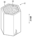
As shown in FIG. 4, theshock absorbing member 12 of the present embodiment includes a regular N-gonal columnar wood 22 having a cross-section of N ≧ 5, and a metal frame 32 that covers the side surface of the wood 22. It receives the compressive load due to impact in the axial direction. FIG. 4 shows the shock absorbing member 12 having a regular hexagonal cross section, that is, N = 6. The materials of the wood 22 and the frame 32 are the same as those of the wood 21 and the frame 31 of the first embodiment, and only the shapes are different.
本実施形態の衝撃吸収部材12は、図4に示すように、断面がN≧5を満たす正N角形の柱状の木材22と、木材22の側面を覆う金属製の枠体32とからなり、衝撃による圧縮荷重を軸方向に受けるものである。なお、図4には断面が正六角形、すなわちN=6の場合の衝撃吸収部材12が示されている。木材22及び枠体32の材質は、上記実施形態1の木材21及び枠体31と同様であり、形状のみが異なる。 [Embodiment 2]
As shown in FIG. 4, the
枠体32は、木材22と等しいNを有する正N角筒状、すなわち断面が中空正N角形である中空筒状である。枠体32は、木材22を支持することができるとともに、軸方向の圧縮荷重を受けて木材22とともに変形することのできるものであり、木材22の外側に隙間無く嵌って、木材22の側面全体を過不足無く覆っている。枠体32の厚みは均一であり、木材22とともに変形可能な範囲で適宜設定され、木材23の外寸とのバランスは特に規定されない。
The frame body 32 is a regular N square cylinder having N equal to the wood 22, that is, a hollow cylinder having a hollow regular N square cross section. The frame 32 can support the timber 22 and can be deformed together with the timber 22 by receiving an axial compressive load. Is covered without excess or deficiency. The thickness of the frame body 32 is uniform and is appropriately set within a range that can be deformed together with the wood 22, and the balance with the outer dimensions of the wood 23 is not particularly specified.
衝撃吸収部材12に軸方向の圧縮荷重が作用すると、その原理は必ずしも明らかではないが、枠体32は外側にのみ繰り返し膨らみながら軸方向に押し潰される。同時に、木材22は枠体32により転倒が抑制されて軸方向にそのまま圧縮変形する。かかる衝撃吸収部材12によれば、軸方向の圧縮荷重が作用すると、木材21を囲う枠体32が軸方向を変えることなく潰れるため、木材22が転倒することなく繊維方向に沿って真っ直ぐ圧縮変形する。その際、枠体32が、内側には入り込まずに外側に膨らみながら潰れるため、木材22に食い込みにくく、木材本来の特徴を最大限に活かすことができる。また、枠体32と木材22とが互いに干渉しにくいので、木材の変形挙動のばらつきを抑えることができる。また、反力の変動を小さく抑えて、衝撃吸収性能のばらつきを小さくすることができる。
When a compressive load in the axial direction acts on the shock absorbing member 12, the principle is not necessarily clear, but the frame 32 is crushed in the axial direction while repeatedly bulging outward only. At the same time, the wood 22 is prevented from falling by the frame body 32 and is compressed and deformed in the axial direction as it is. According to the shock absorbing member 12, when an axial compressive load is applied, the frame 32 surrounding the wood 21 is crushed without changing the axial direction, so that the wood 22 does not fall down and is directly compressed and deformed along the fiber direction. To do. At that time, the frame body 32 does not enter the inside and is crushed while expanding outside, so that it is difficult to bite into the wood 22 and the original features of the wood can be utilized to the maximum. Further, since the frame body 32 and the wood 22 are unlikely to interfere with each other, variations in the deformation behavior of the wood can be suppressed. Further, variation in the reaction force can be suppressed, and variation in shock absorbing performance can be reduced.
[実施形態3]
本実施形態の衝撃吸収部材13は、図5に示すように、断面が正円形の柱状の木材23と、木材23の側面を覆う金属製の枠体33とからなり、衝撃による圧縮荷重を軸方向に受けるものである。木材23及び枠体33の材質は、上記実施形態1の木材21及び枠体31と同様であり、形状のみが異なる。 [Embodiment 3]
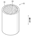
As shown in FIG. 5, theimpact absorbing member 13 of the present embodiment includes a columnar wood 23 having a regular circular cross section and a metal frame 33 covering the side surface of the wood 23, and compresses a compressive load caused by the impact. It will be received in the direction. The materials of the wood 23 and the frame 33 are the same as those of the wood 21 and the frame 31 of the first embodiment, and only the shapes are different.
本実施形態の衝撃吸収部材13は、図5に示すように、断面が正円形の柱状の木材23と、木材23の側面を覆う金属製の枠体33とからなり、衝撃による圧縮荷重を軸方向に受けるものである。木材23及び枠体33の材質は、上記実施形態1の木材21及び枠体31と同様であり、形状のみが異なる。 [Embodiment 3]
As shown in FIG. 5, the
枠体33は、正円筒状、すなわち断面が中空正円形の中空筒状である。枠体33は、木材23を支持することができるとともに、軸方向の圧縮荷重を受けて木材23とともに変形することのできるものであり、木材23の外側に隙間無く嵌って、木材23の側面全体を過不足無く覆っている。枠体33の厚みは均一であり、木材23とともに変形可能な範囲で適宜設定され、木材23の外寸とのバランスは特に規定されない。
The frame body 33 has a regular cylindrical shape, that is, a hollow cylindrical shape having a hollow regular circular cross section. The frame 33 can support the wood 23 and can be deformed together with the wood 23 by receiving an axial compressive load. The frame 33 fits on the outside of the wood 23 without a gap, and the entire side surface of the wood 23. Is covered without excess or deficiency. The thickness of the frame 33 is uniform and is appropriately set within a range that can be deformed together with the wood 23, and the balance with the outer dimensions of the wood 23 is not particularly specified.
衝撃吸収部材13に軸方向の圧縮荷重が作用すると、その原理は必ずしも明らかではないが、木材23を囲う枠体33は外側にのみ繰り返し膨らみながら軸方向に押し潰される。同時に、木材23は枠体33により転倒が抑制されて軸方向にそのまま圧縮変形する。かかる衝撃吸収部材13によれば、軸方向の圧縮荷重が作用すると、木材23を囲う枠体33が軸方向を変えることなく潰れるため、木材23が転倒することなく繊維方向に沿って真っ直ぐ圧縮変形する。その際、枠体33が、内側には折れ曲がらずに外側に折れ曲がりながら潰れるため、木材23に食い込みにくく、木材本来の特徴を最大限に活かすことができる。また、枠体33と木材23とが互いに干渉しにくいので、木材の変形挙動のばらつきを抑えることができる。また、反力の変動を小さく抑えて、衝撃吸収性能のばらつきを小さくすることができる。
When an axial compressive load acts on the shock absorbing member 13, the principle is not necessarily clear, but the frame 33 surrounding the wood 23 is squeezed in the axial direction while repeatedly bulging outward only. At the same time, the timber 23 is prevented from falling by the frame 33 and is compressed and deformed in the axial direction as it is. According to the shock absorbing member 13, when an axial compressive load is applied, the frame 33 surrounding the wood 23 is crushed without changing the axial direction, so that the wood 23 is straightly compressed and deformed along the fiber direction without falling down. To do. At that time, the frame body 33 is not bent inward but is crushed while bending outward, so that it is difficult to bite into the wood 23 and the original features of the wood can be utilized to the maximum. Moreover, since the frame 33 and the wood 23 are unlikely to interfere with each other, variation in the deformation behavior of the wood can be suppressed. Further, variation in the reaction force can be suppressed, and variation in shock absorbing performance can be reduced.
[実施形態4]
本実施形態の衝撃吸収部材14、図6に示すように、断面が楕円形の柱状の木材24と、木材24の側面を覆う金属製の枠体34とからなり、衝撃による圧縮荷重を軸方向に受けるものである。木材24及び枠体34の材質は、上記実施形態1の木材21及び枠体31と同様であり、形状のみが異なる。 [Embodiment 4]
As shown in FIG. 6, theshock absorbing member 14 of the present embodiment includes a columnar wood 24 having an elliptical cross section and a metal frame 34 that covers the side surface of the wood 24, and compresses a compressive load caused by the impact in the axial direction. It is intended for The materials of the wood 24 and the frame 34 are the same as those of the wood 21 and the frame 31 of the first embodiment, and only the shapes are different.
本実施形態の衝撃吸収部材14、図6に示すように、断面が楕円形の柱状の木材24と、木材24の側面を覆う金属製の枠体34とからなり、衝撃による圧縮荷重を軸方向に受けるものである。木材24及び枠体34の材質は、上記実施形態1の木材21及び枠体31と同様であり、形状のみが異なる。 [Embodiment 4]
As shown in FIG. 6, the
枠体34は、楕円筒状、すなわち断面が中空楕円形の中空筒状である。枠体34の中空楕円形断面の内側の長径の短径に対する比a/b(以下、長径対短径比という)が3以下である(図7参照)。ここで、長径対短径比a/bが1に等しい場合に断面形状は中空正円形となるので、正確には1<a/b≦3を満たす比である。枠体34は、木材24を支持することができるとともに、軸方向の圧縮荷重を受けて木材23とともに変形することのできるものであり、木材23の外側に隙間無く嵌って、木材23の側面全体を過不足無く覆っている。枠体34の厚みは均一であり、木材24とともに変形可能な範囲で適宜設定される。
The frame body 34 has an elliptic cylindrical shape, that is, a hollow cylindrical shape having a hollow elliptical cross section. The ratio a / b of the major axis to the minor axis inside the hollow elliptical cross section of the frame 34 (hereinafter referred to as the ratio of major axis to minor axis) is 3 or less (see FIG. 7). Here, when the ratio of the major axis to minor axis a / b is equal to 1, the cross-sectional shape is a hollow circular shape, and therefore exactly 1 <a / b ≦ 3. The frame 34 can support the wood 24 and can be deformed together with the wood 23 by receiving an axial compressive load. Is covered without excess or deficiency. The thickness of the frame 34 is uniform, and is set as appropriate within a range that can be deformed together with the wood 24.
衝撃吸収部材14に軸方向の圧縮荷重が作用すると、木材24を囲う枠体34は、その原理は必ずしも明らかではないが、外側にのみ繰り返し膨らみながら軸方向に押し潰され、同時に木材24は圧縮変形する。その際、枠体34が、内側には折れ曲がらずに外側に折れ曲がりながら潰れるため、木材24に食い込みにくく木材本来の特徴が的確に発揮される。また、枠体34と木材24とが互いに干渉しにくいので、木材の変形挙動のばらつきを抑えることができる。また、反力の変動を小さく抑えて、衝撃吸収性能のばらつきを小さくすることができる。
When an axial compressive load is applied to the shock absorbing member 14, the principle of the frame 34 surrounding the wood 24 is not necessarily clear, but it is crushed in the axial direction while repeatedly inflating only to the outside, and at the same time the wood 24 is compressed. Deform. At this time, the frame body 34 is not folded inward but is crushed while being bent outward, so that it is difficult to bite into the wood 24 and the original features of the wood are precisely exhibited. In addition, since the frame body 34 and the wood 24 are unlikely to interfere with each other, variations in the deformation behavior of the wood can be suppressed. Further, variation in the reaction force can be suppressed, and variation in shock absorbing performance can be reduced.
[試験1]
試験1は、木材本来の衝撃吸収性能を確認することを目的とした。繊維方向が軸方向(圧縮方向)と平行になるように製材された、断面が正方形のスギの角材(40mm×40mm×軸方向長さ70mm)を用意し、枠体が外嵌されていない状態で株式会社島津製作所製の圧縮試験機(オートグラフAG-100KNE型)へ設置し、2mm/minの条件で軸方向に圧縮した場合の、変位(圧縮量)と圧縮荷重(すなわち衝撃吸収部材の発揮する反力)との関係を測定した。その結果を図8に示す。 [Test 1]
Test 1 aimed to confirm the original shock absorbing performance of wood. A cedar square (40 mm x 40 mm x axial length 70 mm) with a square cross-section is prepared so that the fiber direction is parallel to the axial direction (compression direction), and the frame is not externally fitted Installed in a compression tester manufactured by Shimadzu Corporation (autograph AG-100KNE type) and compressed in the axial direction under the condition of 2 mm / min, the displacement (compression amount) and the compression load (that is, the impact absorbing member) (Reaction force exerted) was measured. The result is shown in FIG.
試験1は、木材本来の衝撃吸収性能を確認することを目的とした。繊維方向が軸方向(圧縮方向)と平行になるように製材された、断面が正方形のスギの角材(40mm×40mm×軸方向長さ70mm)を用意し、枠体が外嵌されていない状態で株式会社島津製作所製の圧縮試験機(オートグラフAG-100KNE型)へ設置し、2mm/minの条件で軸方向に圧縮した場合の、変位(圧縮量)と圧縮荷重(すなわち衝撃吸収部材の発揮する反力)との関係を測定した。その結果を図8に示す。 [Test 1]
図8から明らかなように、木材をその繊維方向に沿って圧縮すると、圧縮荷重は極めて安定的に推移し、高い衝撃吸収性能を発揮することが確認された。
As is clear from FIG. 8, it was confirmed that when wood was compressed along its fiber direction, the compressive load changed extremely stably and exhibited high shock absorption performance.
[試験2]
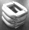
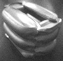
試験2では、上記実施形態1に従って、断面形状が正方形の木材の外側に中空筒状の枠体を嵌装してなるNo.1、2の衝撃吸収部材の試料を用意した。木材としてスギの角材を用い、枠体にはアルミニウム(A5052)の押出成形品を用いた。各試料の寸法については表1に示す。なお、表1中の中空正方形断面の外側の一辺L及び枠体の厚みTは、図2に示すL及びTに対応している。 [Test 2]
InTest 2, according to the above-mentioned Embodiment 1, a hollow cylindrical frame was fitted to the outside of a wood having a square cross-sectional shape. Samples of 1 and 2 impact absorbing members were prepared. A cedar square was used as the wood, and an extruded product of aluminum (A5052) was used as the frame. The dimensions of each sample are shown in Table 1. In addition, the outer side L and the frame thickness T of the hollow square cross section in Table 1 correspond to L and T shown in FIG.
試験2では、上記実施形態1に従って、断面形状が正方形の木材の外側に中空筒状の枠体を嵌装してなるNo.1、2の衝撃吸収部材の試料を用意した。木材としてスギの角材を用い、枠体にはアルミニウム(A5052)の押出成形品を用いた。各試料の寸法については表1に示す。なお、表1中の中空正方形断面の外側の一辺L及び枠体の厚みTは、図2に示すL及びTに対応している。 [Test 2]
In

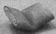
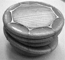
次いで、No.1の試料を上記試験1と同様に軸方向に圧縮し、変位と圧縮荷重との関係を測定した。また、枠体のみを同様に圧縮して変位と圧縮荷重との関係も測定した。そして、木材に枠体が嵌装された試料の結果から枠体のみの結果を差し引き、試料中の木材のみについての変位と圧縮荷重との関係を求めた。その結果を図9に示す。また、図10に、圧縮後の試料の状態を写真で示す。No.2の試料についてもNo.1と同様に試料中の木材の変位と圧縮荷重との関係を求め、その結果を同様に図11、12に示す。
Next, No. Sample 1 was compressed in the axial direction in the same manner as in Test 1 above, and the relationship between displacement and compression load was measured. Further, only the frame was compressed in the same manner, and the relationship between the displacement and the compressive load was also measured. And the result of only the frame was subtracted from the result of the sample in which the frame was fitted to the wood, and the relationship between the displacement and the compressive load for only the wood in the sample was determined. The result is shown in FIG. FIG. 10 shows a photograph of the state of the sample after compression. No. No. 2 was also No. Similar to 1, the relationship between the displacement of the wood in the sample and the compressive load was determined, and the results are also shown in FIGS.
各試料中の木材の変位と圧縮荷重との関係を示す図9と図11のグラフを比較すると明らかなように、断面の一辺対厚み比L/Tが20のNo.1に比べ、断面の一辺対厚み比L/Tが10のNo.2では、木材の圧縮荷重の変動が極めて小さかった。そして、No.2の試料中の木材の圧縮荷重は、木材のみを圧縮した試験1の結果と同様に安定していた。そこで、各試料の変形形態に注目したところ、いずれも中の木材は倒れることなく圧縮変形していたが、枠体の変形の態様は異なっていた。No.1の試料では、図10の写真が示すように、枠体が、隣接する壁面が交互に内側と外側とに折れ曲がりながら潰れていた。その結果、内側に折れ曲がった枠体が木材に食い込んでいた。これに対し、No.2の試料では、図12の写真が示すように、枠体が、全周が外側に拡がるように膨らむ変形を繰り返しながら潰れていた。そして、No.2の試料では、枠体が内側に入り込むことなく潰れており、枠体は木材に食い込んでいなかった。これらの結果から、断面が正方形の試料では、断面の一辺対厚み比L/Tが特定の値をとる場合にのみ、枠体が外側にのみ膨らみながら圧縮し、木材へ食い込まないことが明らかとなった。その結果、木材本来の機能を的確に発揮させることができ、圧縮荷重を安定させられることが明らかとなった。
As is clear from comparison of the graphs of FIG. 9 and FIG. 11 showing the relationship between the displacement of the wood in each sample and the compressive load, a No. with a side-to-side thickness ratio L / T of 20 is shown. No. 1 in which the ratio L / T on one side to the thickness is 10 In 2, the fluctuation of the compression load of the wood was extremely small. And No. The compression load of the wood in the sample No. 2 was stable similarly to the result of Test 1 in which only the wood was compressed. Therefore, when attention was paid to the deformation form of each sample, the wood inside was compressed and deformed without falling down, but the deformation of the frame was different. No. In the sample of 1, as shown in the photograph of FIG. 10, the frame body was crushed while the adjacent wall surfaces were alternately bent to the inside and the outside. As a result, the frame that was bent inward bited into the wood. In contrast, no. In the sample of 2, as shown in the photograph of FIG. 12, the frame body was crushed while repeatedly deforming so that the entire circumference expanded outward. And No. In the sample of 2, the frame body was crushed without entering inside, and the frame body did not bite into the wood. From these results, it is clear that in the case of a sample having a square cross section, the frame is compressed while expanding only outward when the side to thickness ratio L / T takes a specific value and does not bite into the wood. became. As a result, it has been clarified that the original function of wood can be exhibited accurately and the compressive load can be stabilized.
[試験3]
そこで、試験3では、軸方向の断面形状が正方形の中空筒状の枠体のみからなる試料を用意し、試験2と同様に上記試験1と同様に圧縮し、変形の形態を観察した。図13~16に、圧縮後の試料の状態を写真で示す。なお、試験3では、アルミニウム(A5052)を押出成形して得たA~Dの枠体を試料とした。A~Dの枠体は、それぞれ中空正方形断面の外側の一辺Lは20mmであり、軸方向の長さは70mmとした。厚みのみが異なっている。各枠体の寸法を表2に示すとともに、その圧縮変形の形態を併記する。なお、表2においては、圧縮変形の形態について、試験2のNo.1の試料のように内側にも外側にも折れ曲がりながら潰れていた場合には「不適」、No.2の試料のように外側にのみ膨らみながら潰れていた場合には「良好」と記した。 [Test 3]
Therefore, in Test 3, a sample consisting only of a hollow cylindrical frame having a square cross-sectional shape in the axial direction was prepared, compressed in the same manner as inTest 1 above, and observed for deformation. FIGS. 13 to 16 show photographs of the sample after compression. In Test 3, a frame of A to D obtained by extrusion molding of aluminum (A5052) was used as a sample. In each of the frames A to D, the outer side L of the hollow square cross section was 20 mm, and the axial length was 70 mm. Only the thickness is different. The dimensions of each frame are shown in Table 2, and the form of compression deformation is also shown. In Table 2, the No. of Test 2 is shown for the form of compression deformation. In the case where the sample was crushed while being bent inwardly or outwardly as in the case of the sample of No. 1, it was “unsuitable”. When it was crushed while expanding only outward as in the sample of 2, it was marked as “good”.
そこで、試験3では、軸方向の断面形状が正方形の中空筒状の枠体のみからなる試料を用意し、試験2と同様に上記試験1と同様に圧縮し、変形の形態を観察した。図13~16に、圧縮後の試料の状態を写真で示す。なお、試験3では、アルミニウム(A5052)を押出成形して得たA~Dの枠体を試料とした。A~Dの枠体は、それぞれ中空正方形断面の外側の一辺Lは20mmであり、軸方向の長さは70mmとした。厚みのみが異なっている。各枠体の寸法を表2に示すとともに、その圧縮変形の形態を併記する。なお、表2においては、圧縮変形の形態について、試験2のNo.1の試料のように内側にも外側にも折れ曲がりながら潰れていた場合には「不適」、No.2の試料のように外側にのみ膨らみながら潰れていた場合には「良好」と記した。 [Test 3]
Therefore, in Test 3, a sample consisting only of a hollow cylindrical frame having a square cross-sectional shape in the axial direction was prepared, compressed in the same manner as in

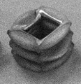
表2の結果から、枠体の断面の一辺対厚み比L/Tを9~12とすれば、枠体が、全周が外側に拡がるように膨らむ変形を繰り返しながら潰れ、内側には入り込まないことが明らかとなった(図14、15参照)。一方、枠体の断面の一辺対厚み比L/Tが9~12を外れると、隣接する壁面が交互に内側と外側とに折れ曲がりながら潰れており、枠体の一部が内方に入り込んでいた(図13、16参照)。
From the results of Table 2, if the ratio of one side to thickness L / T of the cross section of the frame is 9 to 12, the frame is crushed while repeatedly deforming so that the entire circumference expands outward, and does not enter the inside. (See FIGS. 14 and 15). On the other hand, when the one-side to thickness ratio L / T of the cross section of the frame body deviates from 9 to 12, adjacent wall surfaces are crushed while alternately bending inside and outside, and a part of the frame body enters inside. (See FIGS. 13 and 16).
[試験4]
試験4では、試験3と同様に、軸方向の断面形状が正方形の中空筒状の枠体を試料とし、試験3と同様に圧縮し、変形の形態を観察した。この試験4では、表3に示すような中空正方形断面の外側の一辺Lや軸方向の長さも異なるE~Kの枠体を試験に供した。なお、試験4では、アルミニウム(A6063)を押出成形して各試料を得た。試験3と同様に圧縮変形の形態を表3に併記する。 [Test 4]
In Test 4, as in Test 3, a hollow cylindrical frame having a square cross-sectional shape in the axial direction was used as a sample, compressed in the same manner as in Test 3, and the deformation was observed. In this test 4, frames E to K having different outer side L and axial length as shown in Table 3 were used for the test. In Test 4, aluminum (A6063) was extruded to obtain each sample. Similar to Test 3, the form of compression deformation is also shown in Table 3.

表3に示す結果から、中空正方形断面の外側の一辺Lや軸方向長さを変更しても、断面の一辺対厚み比L/Tが9~12でありさえすれば、枠体が、全周が外側に拡がるように膨らむ変形を繰り返しながら潰れ、内側には入り込まないことが確認された。図17に、代表して、枠体Kの圧縮後の状態を写真で示す。
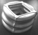
From the results shown in Table 3, even if the outer side L and the axial length of the hollow square cross section are changed, as long as the one side to thickness ratio L / T of the cross section is 9 to 12, the frame body is completely It was confirmed that it was crushed while repeatedly deforming so that its circumference expanded to the outside and did not enter the inside. FIG. 17 representatively shows a state after compression of the frame body K with a photograph.
[試験5]
試験5では、表4に示す断面形状が中空長方形であるような中空筒状の枠体を試料とし、試験3、4と同様に圧縮し、変形の形態を観察した。その結果を、試験3、4と同様に表4に併記する。なお、試験5では、アルミニウム(A6063)を押出成形して各試料を得た。表4に示す外側の短辺、外側の長辺とは、それぞれ中空長方形断面の外側の短辺、長辺の長さである。 [Test 5]
InTest 5, a hollow cylindrical frame having a hollow rectangular cross section shown in Table 4 was used as a sample, compressed in the same manner as in Tests 3 and 4, and the deformation was observed. The results are also shown in Table 4 as in Tests 3 and 4. In Test 5, aluminum (A6063) was extruded to obtain each sample. The outer short side and the outer long side shown in Table 4 are the length of the outer short side and the long side, respectively, of the hollow rectangular cross section.
試験5では、表4に示す断面形状が中空長方形であるような中空筒状の枠体を試料とし、試験3、4と同様に圧縮し、変形の形態を観察した。その結果を、試験3、4と同様に表4に併記する。なお、試験5では、アルミニウム(A6063)を押出成形して各試料を得た。表4に示す外側の短辺、外側の長辺とは、それぞれ中空長方形断面の外側の短辺、長辺の長さである。 [Test 5]
In

表4から明らかなように、試験5においては、枠体の長方形断面の外側の短辺の厚みに対する比(短辺対厚み比)を9~12としても、外側にのみ膨らみながら潰れる変形とはならず、内側と外側とに折れ曲がりながら潰れていた。図18、19に、代表して枠体S、Vの圧縮後の状態を写真で示す。この結果から、枠体の断面が四角形の場合、特に正方形の場合には、枠体の短辺対厚み比を9~12とすることで外側にのみ膨らみながら潰れるようにすることができることが明らかとなった。
As can be seen from Table 4, in Test 5, even when the ratio of the short side of the rectangular cross section of the frame body to the thickness of the short side (short side to thickness ratio) is 9 to 12, it is a deformation that collapses while expanding only outward. Rather, it was crushed while bending inside and outside. In FIGS. 18 and 19, the state after compression of the frames S and V is shown as a photograph. From this result, it is clear that when the cross section of the frame is a quadrangle, in particular, when it is a square, the frame can be crushed while only bulging outward by setting the short side to thickness ratio of 9 to 12. It became.
[試験6]
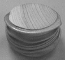
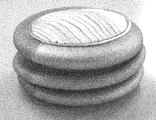
試験6では、上記実施形態3又は4に従って、軸方向の断面形状が円形の木材の外側に中空筒状の枠体を嵌装してなるNo.3~8の衝撃吸収部材の試料を用意した。木材としてスギの製材を用い、枠体にはアルミニウム(A5052)の押出成形品を用いた。各試料の寸法については表5に示す。なお、表5中の長径a及び短径bは、図7に示すa及びbに対応している。次いで、No.3~8の各試料について、上記試験2と同様に圧縮し、変形の形態を観察した。図20~25に圧縮後の各試料の状態を写真で示す。また、圧縮変形の形態について、表5に併記する。表5では、外側にのみ膨らみながら潰れていた場合には「良好」と記し、その他の場合は注釈を付す。 [Test 6]
In Test 6, according to Embodiment 3 or 4 above, a hollow cylindrical frame was fitted on the outside of a wood having a circular cross-sectional shape in the axial direction. Samples of 3 to 8 impact absorbing members were prepared. Cedar lumber was used as the wood, and an aluminum (A5052) extruded product was used as the frame. The dimensions of each sample are shown in Table 5. In addition, the major axis a and the minor axis b in Table 5 correspond to a and b shown in FIG. Then, No. Each sample of 3 to 8 was compressed in the same manner as inTest 2 above, and the deformation was observed. 20 to 25 show photographs of the state of each sample after compression. Further, the form of compression deformation is also shown in Table 5. In Table 5, “good” is indicated when the material is crushed while only bulging outward, and a comment is attached in other cases.
試験6では、上記実施形態3又は4に従って、軸方向の断面形状が円形の木材の外側に中空筒状の枠体を嵌装してなるNo.3~8の衝撃吸収部材の試料を用意した。木材としてスギの製材を用い、枠体にはアルミニウム(A5052)の押出成形品を用いた。各試料の寸法については表5に示す。なお、表5中の長径a及び短径bは、図7に示すa及びbに対応している。次いで、No.3~8の各試料について、上記試験2と同様に圧縮し、変形の形態を観察した。図20~25に圧縮後の各試料の状態を写真で示す。また、圧縮変形の形態について、表5に併記する。表5では、外側にのみ膨らみながら潰れていた場合には「良好」と記し、その他の場合は注釈を付す。 [Test 6]
In Test 6, according to Embodiment 3 or 4 above, a hollow cylindrical frame was fitted on the outside of a wood having a circular cross-sectional shape in the axial direction. Samples of 3 to 8 impact absorbing members were prepared. Cedar lumber was used as the wood, and an aluminum (A5052) extruded product was used as the frame. The dimensions of each sample are shown in Table 5. In addition, the major axis a and the minor axis b in Table 5 correspond to a and b shown in FIG. Then, No. Each sample of 3 to 8 was compressed in the same manner as in

No.3~6の試料の結果から、試料の断面が円形の場合、正円形に限らず、楕円形でも枠体の厚みに関係なく全周が外側に拡がるように膨らむ変形を繰り返しながら潰れ、内側には入り込まないことが明らかとなった。なお、断面が楕円形で枠体が肉薄のNo.5の試料は、図22Aの写真が示すように軸がずれて斜めに潰れたものの、枠体は内方へは入り込まず外方に膨らみながら潰れ、木材へ食い込まなかった。そのため、木材の繊維が不規則に傾くことはなく、図22Bのグラフが示すように圧縮荷重が安定的に推移した。また、No.5~8の試料の結果から、断面が楕円形の場合、その楕円形が平らになりすぎると、試料全体が座屈しやすくなることも明らかとなり、楕円形断面の長径対短径比a/bを3以下とするのが好ましいことがわかった。
No. From the results of the samples 3 to 6, when the cross section of the sample is circular, the shape of the sample is not limited to a regular circle, and even an ellipse is crushed while repeatedly deforming so that the entire circumference expands to the outside regardless of the thickness of the frame. It was revealed that would not enter. In addition, No. whose cross section is elliptical and the frame is thin. As shown in the photograph of FIG. 22A, the sample of No. 5 was crushed obliquely with its axis shifted, but the frame did not enter inward but swelled outward and did not penetrate into the wood. Therefore, the fiber of wood did not incline irregularly, and the compressive load changed stably as the graph of FIG. 22B shows. No. From the results of the samples 5 to 8, when the cross section is elliptical, it becomes clear that if the elliptical shape becomes too flat, the entire sample is likely to buckle, and the ratio of major axis to minor axis of the elliptical section is a / b. It was found that it is preferable to set the value to 3 or less.
試験2~6の結果、試料の断面形状が四角形から円形に近づくほど、枠体の厚みや断面形状の平たさに関係なく外側にのみ膨らみながら潰れやすくなることが推察された。そこで、次の試験7では、断面形状が四角形よりも円形に近い多角形の場合について、変形の態様を調べた。
As a result of Tests 2 to 6, it was inferred that the closer the cross-sectional shape of the sample was from a square to a circular shape, the easier it was to collapse while bulging only outward, regardless of the thickness of the frame and the flatness of the cross-sectional shape. Therefore, in the next test 7, the deformation mode was examined in the case where the cross-sectional shape was a polygon closer to a circle than a quadrangle.
[試験7]
試験7では、上記実施形態2に従って断面形状が多角形であるNo.9~12の衝撃吸収部材の試料を用意した。木材としてスギの製材を用い、枠体にはアルミニウム(A5052)の押出成形品を用いた。各試料の形状及び寸法については表6に示す。次いで、No.9~12の各試料について、上記試験7と同様に圧縮し、変形の形態を観察した。圧縮変形の形態について、表6に併記する。表6では、外側にのみ膨らみながら潰れていた場合には「良好」と記す。 [Test 7]
In Test 7, according to the second embodiment, the cross-sectional shape is a polygonal shape. Samples of 9 to 12 impact absorbing members were prepared. Cedar lumber was used as the wood, and an aluminum (A5052) extruded product was used as the frame. Table 6 shows the shape and dimensions of each sample. Then, No. Each of the samples 9 to 12 was compressed in the same manner as in Test 7 above, and the deformation was observed. The form of compression deformation is also shown in Table 6. In Table 6, when it is crushed while expanding only outside, it is described as “good”.

No.9~11の試料の結果から、断面形状が正六角形の場合には、枠体は、厚みに関係なく全周が外側に拡がるように膨らむ変形を繰り返しながら潰れ、内側には入り込まないことが明らかとなった。図26に、代表してNo.11の試料の圧縮後の状態を写真で示す。また、断面形状が正八角形の場合にも、図27の写真が示すように枠体が全周が外側に拡がるように膨らむ変形を繰り返しながら潰れ、内側には入り込まないことが確認された。これにより、断面形状をN≧5を満たす正N角形とするのが好ましいことがわかった。
No. From the results of the samples 9 to 11, it is clear that when the cross-sectional shape is a regular hexagon, the frame body is crushed while repeatedly deforming so that the entire circumference expands to the outside regardless of the thickness, and does not enter the inside. It became. In FIG. The state after compression of 11 samples is shown by a photograph. Further, even when the cross-sectional shape is a regular octagon, as shown in the photograph of FIG. 27, it was confirmed that the frame body was crushed while repeatedly deforming so that the entire circumference expanded outward, and did not enter the inside. Thereby, it turned out that it is preferable to make a cross-sectional shape into the regular N square which satisfy | fills N> = 5.
Claims (3)
- 柱状の木材と、該木材の側面を覆う金属製の中空筒状の枠体とを備え、衝突時の衝撃による圧縮荷重を前記木材の軸方向に受ける車両の衝撃吸収部材であって、
前記枠体は正四角筒状であり、該枠体の中空正方形断面の外側の一辺の厚みに対する比が9~12である、衝撃吸収部材。 A shock absorbing member for a vehicle that includes a columnar timber and a metal hollow cylindrical frame that covers a side surface of the timber, and receives a compressive load caused by an impact at the time of a collision in the axial direction of the wood,
The impact-absorbing member, wherein the frame body is a regular square cylinder, and the ratio of the frame body to the thickness of one side outside the hollow square cross section is 9-12. - 柱状の木材と、該木材の側面を覆う金属製の中空筒状の枠体とを備え、衝突時の衝撃による圧縮荷重を前記木材の軸方向に受ける車両の衝撃吸収部材であって、
前記枠体はN≧5を満たす正N角筒状又は正円筒状である、衝撃吸収部材。 A shock absorbing member for a vehicle that includes a columnar timber and a metal hollow cylindrical frame that covers a side surface of the timber, and receives a compressive load caused by an impact at the time of a collision in the axial direction of the wood,
The frame body is a shock absorbing member having a regular N-square cylindrical shape or a regular cylindrical shape satisfying N ≧ 5. - 柱状の木材と、該木材の側面を覆う金属製の中空筒状の枠体とを備え、衝突時の衝撃による圧縮荷重を前記木材の軸方向に受ける車両の衝撃吸収部材であって、
前記枠体は楕円筒状であり、該枠体の中空楕円断面の内側の長径aの短径bに対する比a/bが3以下である、衝撃吸収部材。
A shock absorbing member for a vehicle that includes a columnar timber and a metal hollow cylindrical frame that covers a side surface of the timber, and receives a compressive load caused by an impact at the time of a collision in the axial direction of the wood,
The impact-absorbing member, wherein the frame is an elliptic cylinder, and the ratio a / b of the major axis a to the minor axis b inside the hollow elliptical cross section of the frame is 3 or less.
Priority Applications (2)
| Application Number | Priority Date | Filing Date | Title |
|---|---|---|---|
| US14/368,482 US9221413B2 (en) | 2011-12-26 | 2012-12-05 | Vehicle impact-absorbing member |
| EP12862992.0A EP2799289B1 (en) | 2011-12-26 | 2012-12-05 | Vehicle shock absorption member |
Applications Claiming Priority (2)
| Application Number | Priority Date | Filing Date | Title |
|---|---|---|---|
| JP2011-283389 | 2011-12-26 | ||
| JP2011283389A JP5776537B2 (en) | 2011-12-26 | 2011-12-26 | Shock absorber for vehicle |
Publications (1)
| Publication Number | Publication Date |
|---|---|
| WO2013099542A1 true WO2013099542A1 (en) | 2013-07-04 |
Family
ID=48697039
Family Applications (1)
| Application Number | Title | Priority Date | Filing Date |
|---|---|---|---|
| PCT/JP2012/081520 WO2013099542A1 (en) | 2011-12-26 | 2012-12-05 | Vehicle shock absorption member |
Country Status (4)
| Country | Link |
|---|---|
| US (1) | US9221413B2 (en) |
| EP (1) | EP2799289B1 (en) |
| JP (1) | JP5776537B2 (en) |
| WO (1) | WO2013099542A1 (en) |
Families Citing this family (11)
| Publication number | Priority date | Publication date | Assignee | Title |
|---|---|---|---|---|
| US9243678B2 (en) * | 2011-11-29 | 2016-01-26 | Toyota Shatai Kabushiki Kaisha | Impact absorbing unit for a vehicle |
| JP5791676B2 (en) * | 2013-09-10 | 2015-10-07 | 富士重工業株式会社 | Shock absorber |
| JP6393921B2 (en) * | 2013-11-20 | 2018-09-26 | 藤森工業株式会社 | Adhesive composition and surface protective film |
| JP6560568B2 (en) * | 2015-09-07 | 2019-08-14 | 株式会社Subaru | Energy absorbing structure |
| JP6558316B2 (en) * | 2016-07-05 | 2019-08-14 | 株式会社豊田自動織機 | Load energy absorber |
| JP6798457B2 (en) * | 2017-09-15 | 2020-12-09 | トヨタ自動車株式会社 | Vampari Information |
| JP6863219B2 (en) * | 2017-10-13 | 2021-04-21 | トヨタ自動車株式会社 | Vehicle side structure |
| JP6796244B2 (en) * | 2017-11-15 | 2020-12-09 | トヨタ車体株式会社 | Vehicle shock absorber |
| JP2019217850A (en) * | 2018-06-18 | 2019-12-26 | トヨタ自動車株式会社 | Vehicle lateral structure |
| WO2020053623A1 (en) * | 2018-09-11 | 2020-03-19 | Arcelormittal | Energy absorbing device, motor vehicle body and method for manufacturing thereof |
| JP7125826B2 (en) | 2019-02-18 | 2022-08-25 | トヨタ車体株式会社 | Impact absorbing member and manufacturing method thereof |
Citations (4)
| Publication number | Priority date | Publication date | Assignee | Title |
|---|---|---|---|---|
| JPS5818853U (en) * | 1981-07-30 | 1983-02-05 | 三菱自動車工業株式会社 | Automobile bumper mounting structure |
| JP2001182769A (en) | 1999-12-27 | 2001-07-06 | Showa Alum Corp | Shock-absorbing member |
| JP2004322733A (en) * | 2003-04-22 | 2004-11-18 | Mitsubishi Alum Co Ltd | Vehicular body energy absorbing structure |
| WO2005037518A1 (en) * | 2003-10-17 | 2005-04-28 | Shiina Kasei Co. | Method for producing plastic foamed composite |
Family Cites Families (7)
| Publication number | Priority date | Publication date | Assignee | Title |
|---|---|---|---|---|
| JPS5818853A (en) | 1981-07-24 | 1983-02-03 | Hitachi Ltd | Charged-particle applied device |
| JP5545259B2 (en) * | 2010-12-01 | 2014-07-09 | トヨタ車体株式会社 | Shock absorbing member |
| JP2012218712A (en) * | 2011-04-14 | 2012-11-12 | Toyota Auto Body Co Ltd | Impact absorbing member |
| JP5522114B2 (en) * | 2011-04-26 | 2014-06-18 | トヨタ車体株式会社 | Shock absorbing member |
| WO2013036606A1 (en) * | 2011-09-06 | 2013-03-14 | Dl Manufacturing | Loading dock bumper assembly |
| US9243678B2 (en) * | 2011-11-29 | 2016-01-26 | Toyota Shatai Kabushiki Kaisha | Impact absorbing unit for a vehicle |
| CA2845837A1 (en) * | 2013-03-12 | 2014-09-12 | Dl Manufacturing | Loading dock bumper assembly |
-
2011
- 2011-12-26 JP JP2011283389A patent/JP5776537B2/en active Active
-
2012
- 2012-12-05 US US14/368,482 patent/US9221413B2/en active Active
- 2012-12-05 WO PCT/JP2012/081520 patent/WO2013099542A1/en active Application Filing
- 2012-12-05 EP EP12862992.0A patent/EP2799289B1/en active Active
Patent Citations (4)
| Publication number | Priority date | Publication date | Assignee | Title |
|---|---|---|---|---|
| JPS5818853U (en) * | 1981-07-30 | 1983-02-05 | 三菱自動車工業株式会社 | Automobile bumper mounting structure |
| JP2001182769A (en) | 1999-12-27 | 2001-07-06 | Showa Alum Corp | Shock-absorbing member |
| JP2004322733A (en) * | 2003-04-22 | 2004-11-18 | Mitsubishi Alum Co Ltd | Vehicular body energy absorbing structure |
| WO2005037518A1 (en) * | 2003-10-17 | 2005-04-28 | Shiina Kasei Co. | Method for producing plastic foamed composite |
Also Published As
| Publication number | Publication date |
|---|---|
| EP2799289A1 (en) | 2014-11-05 |
| JP2013132943A (en) | 2013-07-08 |
| EP2799289B1 (en) | 2018-08-08 |
| US9221413B2 (en) | 2015-12-29 |
| US20140346789A1 (en) | 2014-11-27 |
| EP2799289A4 (en) | 2015-08-05 |
| JP5776537B2 (en) | 2015-09-09 |
Similar Documents
| Publication | Publication Date | Title |
|---|---|---|
| WO2013099542A1 (en) | Vehicle shock absorption member | |
| WO2013080863A1 (en) | Shock-absorbing member for vehicle | |
| US7651155B2 (en) | Progressive energy absorber | |
| JP5261490B2 (en) | Shock absorbing member | |
| JP4792036B2 (en) | Shock absorbing member for vehicle | |
| US20070181393A1 (en) | Impact absorbing device of vehicle | |
| EP1892159A2 (en) | Corrugated tubular energy absorbing structure. | |
| US10266207B2 (en) | Bi-hexagonal vehicle beam with cellular structure | |
| WO2017111105A1 (en) | Energy absorbing member | |
| JP5729275B2 (en) | Shock absorber for vehicle | |
| JP5776522B2 (en) | Shock absorber for vehicle | |
| WO2013105438A1 (en) | Impact absorbing structure for vehicle | |
| JP5056191B2 (en) | Energy absorbing member | |
| JP5522191B2 (en) | Vehicle shock absorption structure | |
| JP5465849B2 (en) | Shock absorber and bumper device for vehicle | |
| JP5729274B2 (en) | Vehicle shock absorption structure | |
| JP2006176093A (en) | Bumper and impact absorption structure for vehicle | |
| JPH06144133A (en) | Metal bumper | |
| EP1348884A1 (en) | Formable energy absorber utilizing a foam stabilized corrugated ribbon | |
| JPH07277112A (en) | Shock absorbing stay | |
| US20070113406A1 (en) | Energy absoption element | |
| US20050167963A1 (en) | Energy absorbing steering column geometric sleeve | |
| JP2005162061A (en) | Shock absorbing member for vehicle | |
| JP3099824B2 (en) | Structure for fixing two shock absorbers to a structural member of a vehicle body and shock absorbing component | |
| JP2015044571A (en) | Stay member for underrun protector, and connection structure for the same |
Legal Events
| Date | Code | Title | Description |
|---|---|---|---|
| 121 | Ep: the epo has been informed by wipo that ep was designated in this application |
Ref document number: 12862992 Country of ref document: EP Kind code of ref document: A1 |
|
| WWE | Wipo information: entry into national phase |
Ref document number: 14368482 Country of ref document: US |
|
| NENP | Non-entry into the national phase |
Ref country code: DE |
|
| WWE | Wipo information: entry into national phase |
Ref document number: 2012862992 Country of ref document: EP |