WO2013094425A1 - 気化器のパイロットスクリュ調整角度規制装置 - Google Patents
気化器のパイロットスクリュ調整角度規制装置 Download PDFInfo
- Publication number
- WO2013094425A1 WO2013094425A1 PCT/JP2012/081645 JP2012081645W WO2013094425A1 WO 2013094425 A1 WO2013094425 A1 WO 2013094425A1 JP 2012081645 W JP2012081645 W JP 2012081645W WO 2013094425 A1 WO2013094425 A1 WO 2013094425A1
- Authority
- WO
- WIPO (PCT)
- Prior art keywords
- pilot screw
- tamper cap
- pilot
- screw
- tamper
- Prior art date
- Legal status (The legal status is an assumption and is not a legal conclusion. Google has not performed a legal analysis and makes no representation as to the accuracy of the status listed.)
- Ceased
Links
Images


Classifications
-
- F—MECHANICAL ENGINEERING; LIGHTING; HEATING; WEAPONS; BLASTING
- F02—COMBUSTION ENGINES; HOT-GAS OR COMBUSTION-PRODUCT ENGINE PLANTS
- F02M—SUPPLYING COMBUSTION ENGINES IN GENERAL WITH COMBUSTIBLE MIXTURES OR CONSTITUENTS THEREOF
- F02M19/00—Details, component parts, or accessories of carburettors, not provided for in, or of interest apart from, the apparatus of groups F02M1/00 - F02M17/00
- F02M19/04—Fuel-metering pins or needles
-
- F—MECHANICAL ENGINEERING; LIGHTING; HEATING; WEAPONS; BLASTING
- F02—COMBUSTION ENGINES; HOT-GAS OR COMBUSTION-PRODUCT ENGINE PLANTS
- F02M—SUPPLYING COMBUSTION ENGINES IN GENERAL WITH COMBUSTIBLE MIXTURES OR CONSTITUENTS THEREOF
- F02M3/00—Idling devices for carburettors
- F02M3/08—Other details of idling devices
- F02M3/10—Fuel metering pins; Nozzles
Definitions
- the present invention relates to a pilot screw adjustment angle regulating device for a carburetor, and more particularly, to a device for regulating an adjustment angle of a pilot screw for adjusting the opening area of a pilot outlet hole of a carburetor within a certain range by a tamper cap. Is preferred.
- a carburetor vaporizer
- a pilot outlet hole is formed in the carburetor, and the amount of fuel mixed with air can be adjusted by adjusting the opening area of the carburetor with a pilot screw. That is, if the pilot screw is tightened to reduce the opening area of the pilot outlet hole, the fuel in the air-fuel mixture can be made thinner. On the other hand, if the pilot screw is opened to increase the opening area of the pilot outlet hole, the fuel in the air-fuel mixture can be concentrated.
- the opening area of the pilot outlet hole can be adjusted without limitation, the exhaust gas after burning gasoline may exceed a predetermined regulation value. Therefore, in order to be able to adjust the opening area of the pilot outlet hole only within the regulation of exhaust gas, it is necessary to provide regulation on the adjustment angle (rotatable range) of the pilot screw.
- a tamper cap is provided on the pilot screw (see, for example, Patent Document 1). That is, when the tamper cap is rotated, the adjustment angle of the pilot screw that rotates synchronously with the tamper cap is regulated within a predetermined range by the protruding portion of the tamper cap being locked by the stopper member of the carburetor body.
- metal tamper caps are also available.
- an adhesive is generally used as a fixing means to the pilot screw.
- the tamper cap is made of metal, there is an advantage that the possibility of being destroyed by excessive force is reduced as compared with the resin tamper cap.
- the present invention has been made to solve the above-described problems, and the tamper cap is securely fixed to the pilot screw while allowing the rotation angle of the pilot screw to be adjusted within a certain regulation range.
- the purpose is to prevent falling out.
- a pilot screw adjustment angle regulating device relates to a metal tamper cap that engages with a pilot screw and rotates the pilot screw synchronously, and a protruding portion of the tamper cap. And a stopper member that stops and restricts the rotation angle of the tamper cap within a certain range.
- a plurality of elastically deformable portions that are erected so that a groove is formed at the center and elastically deformable in a direction perpendicular to the longitudinal axis direction are provided at the end of the pilot screw in the longitudinal axis direction.
- the elastically deforming portion and the tamper cap are provided with engaging portions that engage with each other when the tamper cap is assembled to the pilot screw. Furthermore, after the tamper cap is assembled to the pilot screw while engaging a plurality of elastic deformation portions while elastically deforming the plurality of elastic deformation portions, the elastic deformation portions are made incapable of being elastically deformed by being inserted into the grooves. A holding member for holding the engaged state with the tamper cap is provided.
- the pilot screw and the tamper cap are not fixed by the adhesive, but are fixed by the elastic deformation portion and the engaging portion provided in the tamper cap, and formed at the central portion of the elastic deformation portion.
- the engaged state is firmly held by inserting the holding member into the groove. Therefore, it is possible to prevent the tamper cap from being detached from the pilot screw due to excessive force.
- the tamper cap can be securely fixed to the pilot screw so as not to fall off while the rotation angle of the pilot screw can be adjusted within a certain regulation range.
- FIG. 2 is a partially enlarged view of FIG. 1 and a longitudinal sectional view showing a configuration example of a pilot screw adjustment angle regulating device according to the present embodiment. It is an upper top view showing an example of composition of a pilot screw adjustment angle control device by this embodiment. It is a figure which shows the structural example of the pilot screw by this embodiment.
- FIG. 1 is a longitudinal sectional view showing a state in which a tamper cap is fitted to a pilot screw mounted on a carburetor (carburetor).
- FIG. 2 is a partially enlarged view of FIG. 1, and is a longitudinal sectional view showing a configuration example of the pilot screw adjustment angle regulating device according to the present embodiment.
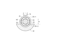
- FIG. 3 is an upper plan view showing a configuration example of the pilot screw adjustment angle regulating device according to the present embodiment.
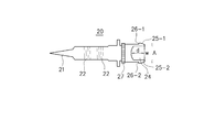
- FIG. 4 is a diagram illustrating a configuration example of a pilot screw according to the present embodiment.
- the carburetor 10 has a fluid passage 11 through which a fluid such as gasoline flows, and a pilot outlet hole 12 is formed at the end of the fluid passage 11.
- a pilot screw 20 is screwed to the carburetor 10, and a tamper cap 30 is fitted to the end of the pilot screw 20.
- a spherical holding member 40 is press-fitted into a groove (details will be described later) formed at the end of the pilot screw 20.
- the pilot screw 20 is made of a metal such as brass, for example.
- the tamper cap 30 is made of a metal such as zinc.
- the tip of the pilot screw 20 is a tapered needle valve portion 21.
- a screw groove 22 is formed in the middle of the pilot screw 20 in the longitudinal axis direction.
- a coil spring 13 is wound around the outer periphery of the pilot screw 20.
- the needle valve portion 21 is inserted into the pilot outlet hole 12 of the carburetor 10 so that the opening area of the pilot outlet hole 12 can be adjusted by screwing.
- Two elasticities that can be elastically deformed in the direction perpendicular to the longitudinal axis direction are erected so that a groove 24 is formed in the central part at the end in the longitudinal axis direction of the pilot screw 20.
- Deformation portions 25 -1 and 25 -2 are provided.
- the cross-sectional shape of the elastically deforming portions 25 -1 and 25 -2 has a shape obtained by partially cutting an annular shape having a certain width.
- These two elastically deforming portions 25 -1 and 25 -2 are provided at positions facing each other with a certain distance therebetween.
- the groove 24 formed between the two elastically deforming portions 25 -1 and 25 -2 has a substantially negative character (-) in cross-sectional shape.
- the elastically deformable portion 25 -1, the 25 -2, the engaging portion 26 -1 for engaging the pilot screw 20 and tamper cap 30 is provided with a 26 -2.
- the tamper cap 30 is assembled to the pilot screw 20 (specifically, elastic deformation portions 25 -1 and 25-2 at the end portions thereof, and so on).
- the engaging portions 33 (see FIGS. 2 and 3) formed inside the tamper cap 30 engage with each other.
- the longitudinal cross-sectional shape of the engaging portions 26 -1 and 26 -2 of the pilot screw 20 is an arrow shape in which the arrow head is only half of the ⁇ shape, and the portion corresponding to the arrow head is the pilot screw. 20 protrudes toward the outer peripheral side.
- the engaging portion 33 of the tamper cap 30 is formed by a step structure using a difference in inner diameter.
- the engagement portion 33 is formed in the stepped portion by making a difference from the inner diameter r2 of the location to be made and making the inner diameter r1 smaller than the inner diameter r2.
- the smaller inner diameter r1 of the tamper cap 30 is a shaft in a state where the elastically deforming portions 25 -1 and 25 -2 are not elastically deformed, that is, in a state where they stand upright in the longitudinal axis direction of the pilot screw 20. (from the outer surface of the shaft portion of one of the elastically deformable portion 25 -1, the other width to the outer surface of the shaft portion of the elastic deformation portion 25 -2) width between or equal, slightly larger set than that.
- the larger inner diameter r2 of the tamper cap 30 is the width between the arrow heads in a state where the elastic deformation portions 25 -1 and 25 -2 are not elastically deformed (the width of the arrow head portion of the one elastic deformation portion 25 -1 ).
- the width from the outer surface to the outer surface of the arrow head portion of the other elastically deformable portion 25-2 is set slightly larger. The reason for setting a little larger is to leave room for the elastically deforming portions 25 -1 and 25 -2 to spread on the outer peripheral side.
- a screw groove 27 is formed at the base of the elastically deforming portions 25 -1 and 25 -2 .
- the thread groove 27 is for giving a resistance so that the tamper cap 30 is not easily detached from the pilot screw 20 when the tamper cap 30 is fitted to the pilot screw 20.
- the outer diameter of the portion where the screw groove 27 is formed is slightly larger than the smaller inner diameter r 1 of the tamper cap 30.
- the outer diameter of the portion where the screw groove 27 is formed is smaller than the larger inner diameter r ⁇ b> 2 of the tamper cap 30.
- the tamper cap 30 includes the engaging portion 33 provided on the inside thereof and the engaging portions 26 -1 and 26 -2 provided on the elastic deformation portions 25 -1 and 25 -2 of the pilot screw 20.
- the fitting state is strengthened by the resistance force provided by the screw groove 27.
- the tamper cap 30 has a structure in which a protruding portion 32 is formed with respect to a substantially cylindrical main body portion 31.
- the cross-sectional shape of the protrusion 32 has a shape obtained by cutting a part from a ring shape having a certain width.
- the carburetor 10 is provided with a stopper member 14 that locks the protruding portion 32 of the tamper cap 30 and restricts the rotation angle of the tamper cap 30 within a certain range. Yes.
- the rotation angle of the pilot screw 20 that rotates synchronously with the tamper cap 30 can be regulated within a certain range by the protruding portion 32 of the tamper cap 30 and the stopper member 14 of the carburetor 10.
- the holding member 40 is engaged with the pilot screw 20 and the tamper cap 30 by press-fitting into the groove 24 formed at the end of the pilot screw 20 after the tamper cap 30 is fitted to the pilot screw 20. It is for holding.
- the holding member 40 has a spherical shape.
- the diameter of the holding member 40 that is, the width with respect to the direction perpendicular to the longitudinal axis direction of the pilot screw 20, is the width w of the groove 24 in a state where the elastically deforming portions 25-1 and 25-2 are not elastically deformed (see FIG. 3 and FIG. 4).
- the holding member 40 is press-fitted into the groove 24 formed at the center of the two elastically deforming portions 25 -1 and 25 -2 . Since the diameter of the holding member 40 is slightly larger than the width w of the groove 24, when the holding member 40 is press-fitted into the groove 24, the two elastically deformable portions 25 -1 and 25 -2 are elastically moved outward by the arrow head portion. Deform. As a result, the elastic deformation to the inside of the elastic deformation portions 25 -1 and 25 -2 becomes impossible. Therefore, the engagement state between the engagement portions 26 -1 and 26 -2 and the engagement portion 33 is not released.
- the diameter of the holding member 40 that is, the height of the pilot screw 20 with respect to the longitudinal axis direction is formed to be substantially the same as the depth d of the groove 24 (see FIG. 4). That is, in a state where the holding member 40 is press-fitted into the groove 24, the end portions of the elastic deformation portions 25 -1 and 25 -2 and the end portion of the holding member 40 are aligned at the same height.
- the metal tamper cap 30 is used, it is destroyed by an excessive force compared to the resin tamper cap. It is possible to reduce the risk of being done.
- the pilot screw 20 and the tamper cap 30 are not fixed by the adhesive, but are engaged with the engaging portions 26 -1 and 26 provided in the elastically deforming portions 25 -1 and 25 -2. -2 and the engaging portion 33 provided in the tamper cap 30. Furthermore, the engagement state is firmly held by inserting the holding member 40 into the groove 24 formed in the central portion of the elastically deforming portions 25 -1 and 25 -2 . Therefore, the inconvenience that the tamper cap 30 is detached from the pilot screw 20 due to excessive force can be prevented. Moreover, the inconvenience that the tamper cap 30 is detached from the pilot screw 20 due to poor adhesion or aging deterioration can be prevented.
- the tamper cap 30 is securely fixed to the pilot screw 20 and dropped off while the rotation angle of the pilot screw 20 can be adjusted within a certain regulation range. You can avoid it.
- the holding member 40 since the diameter of the holding member 40 is slightly larger than the width w of the groove 24, the holding member 40 is press-fitted into the groove 24 with the pilot screw 20 and the tamper cap 30 engaged. As a result, the two elastically deforming portions 25 -1 and 25 -2 are elastically deformed outward. As a result, the elastic deformation portions 25 -1 and 25 -2 cannot be elastically deformed inward at all, and the engagement state between the engagement portions 26 -1 and 26 -2 and the engagement portion 33 is strengthened. can do. Although it is not essential to form the holding member 40 with a diameter slightly larger than the width w of the groove 24, it is preferable to do so.
- the diameter of the holding member 40 is formed substantially in the depth d of the groove 24 the same, by press-fitting the holding member 40 into the groove 24, excessive by inserting a screwdriver or the groove 24 It is possible to make it difficult to apply torque. That is, when the engagement structure as in the present embodiment is employed, it is necessary to provide the groove 24 so that the engagement portions 26 -1 and 26 -2 bend inward. In the present embodiment, the groove 24 is closed by the holding member 40 having the same height as that of the groove 24, so that a screwdriver or the like can be inserted into the groove 24 and the pilot screw 20 cannot be rotated. .
- the pilot screw 20 and the tamper cap 30 are not fixed by an adhesive, and therefore the amount of adhesive applied that greatly affects the non-destructive property of the tamper cap 30 is managed at the production site. There is no need to do such work.
- a drying process is required after the adhesive application process, but in the present embodiment, such a plurality of work processes are not necessary. That is, the operation is completed only by assembling the tamper cap 30 to the pilot screw 20 and press-fitting the holding member 40 into the groove 24 of the pilot screw 20.
- it also has the merit that production efficiency improves.
- an example of forming the elastically deformable portion 25 -1, 25 -2 2 Tsude, the two elastically deformable portions 25 -1, the grooves 24 between 25 -2 approximately minus character form Although described, the present invention is not limited to this. That is, there may be three or more elastic deformation portions.
- the number of elastically deformable portions may be four, and the groove 24 may be formed in the shape of a substantially plus character (+) at the center of the four elastically deformable portions.
- the holding member 40 has a spherical shape, but the present invention is not limited to this.
- the shape of the holding member 40 may be the same as the shape of the groove 24.
- the groove 24 can be completely closed by press-fitting the holding member 40 into the groove 24, so that it is not possible to rotate the pilot screw 20 by inserting a screwdriver or the like into the groove 24. can do.
- the engaging portion 26 -1 arrow-shaped, an example has been described to engage the pilot screw 20 and tamper cap 30 by the engaging portion 33 of the 26 -2 and step structure, the present invention Is not limited to this.
- the engaging portion is configured by a concave portion or a convex portion provided on the outer surface of the shaft portion of the elastically deforming portions 25 -1 and 25 -2 and a convex portion or a concave portion provided on the inner wall surface of the tamper cap 30. May be.
- the structure described in the above embodiment is more preferable in that the engaged state is strong and the tamper cap 30 is less likely to drop off from the pilot screw 20.
Landscapes
- Engineering & Computer Science (AREA)
- Chemical & Material Sciences (AREA)
- Combustion & Propulsion (AREA)
- Mechanical Engineering (AREA)
- General Engineering & Computer Science (AREA)
- Closures For Containers (AREA)
- Toys (AREA)
Abstract
パイロットスクリュ20に嵌着して当該パイロットスクリュ20を同期的に回転させるタンパーキャップ30と、パイロットスクリュ20とタンパーキャップ30とを係合させる係合部26-1,26-2,33と、タンパーキャップ30が嵌着される複数の弾性変形部25-1,25-2と、弾性変形部25-1,25-2の中心部に形成された溝24に圧入され弾性変形部25-1,25-2の弾性変形を不能とすることによって係合状態を保持する保持部材40とを備え、タンパーキャップ30を金属製とすることによって樹脂製よりも非破壊性を強くするとともに、接着剤ではなく機械的構造によってパイロットスクリュ20とタンパーキャップ30とを強固に固定させることができるようにする。
Description
本発明は、気化器のパイロットスクリュ調整角度規制装置に関し、特に、気化器のパイロットアウトレット孔の開口面積を螺動調整するパイロットスクリュの調整角度をタンパーキャップによって一定範囲内に規制する装置に用いて好適なものである。
従来、ガソリンなどを燃料とする燃焼機関において、燃料を霧状にして空気に混合するための装置として、キャブレタ(気化器)が用いられている。通常、キャブレタには、パイロットアウトレット孔が開けられており、その開口面積をパイロットスクリュで螺動調整することにより、空気に混合する燃料の量を調節することが可能となっている。すなわち、パイロットスクリュを締め込んでパイロットアウトレット孔の開口面積を小さくすれば、混合気中の燃料を薄くすることができる。一方、パイロットスクリュを開けてパイロットアウトレット孔の開口面積を大きくすれば、混合気中の燃料を濃くすることができる。
ただし、パイロットアウトレット孔の開口面積を無制限に調整可能にすると、ガソリンを燃焼させた後の排ガスが所定の規制値を超えてしまう場合がある。そのため、排ガスの規制内でのみパイロットアウトレット孔の開口面積を調整可能とするために、パイロットスクリュの調整角度(回転可能範囲)に規制を設けることが必要となる。
従来、このパイロットスクリュの調整角度を規制するための手段として、パイロットスクリュに対してタンパーキャップを設けることが行われている(例えば、特許文献1を参照)。すなわち、タンパーキャップを回転させたときに、タンパーキャップの突出部がキャブレタ本体のストッパ部材で係止されることにより、タンパーキャップと同期的に回転するパイロットスクリュの調整角度が所定範囲内に規制される。
タンパーキャップを用いる場合、排ガス規制を確実に守るために、タンパーキャップがパイロットスクリュに固定されて容易に脱落しないようにすることが必要となる。ところが、上記特許文献1を含む多くの従来技術では、樹脂製のタンパーキャップが使われている。樹脂製の場合、過大な力を加えるとタンパーキャップが破壊され易く、パイロットスクリュが無制限に回転可能な状態となってしまう可能性があった。
一方、金属製のタンパーキャップも提供されている。金属製のタンパーキャップを用いる場合には、一般的にパイロットスクリュへの固定手段として接着剤が用いられる。タンパーキャップを金属製とした場合、樹脂製のタンパーキャップと比べて、過大な力によって破壊されてしまう恐れが少なくなるというメリットがある。
しかしながら、金属製のタンパーキャップ自体の非破壊性が樹脂製に比べて向上するとは言っても、接着剤の接着強度以上の過大な力が加えられると、タンパーキャップがパイロットスクリュから離脱し、パイロットスクリュが無制限に回転可能な状態となってしまうという問題があった。また、接着不良や経年劣化により、タンパーキャップがパイロットスクリュから離脱してしまうこともあるという問題があった。
なお、タンパーキャップを用いる構造ではなく、パイロットスクリュに対して盲栓を施す構造を採用した従来技術も存在する。しかしながら、盲栓式の構造では、パイロットスクリュの角度調整が全くできなくなってしまうという短所も持ち合わせていた。
本発明は、上述のような問題を解決するために成されたものであり、パイロットスクリュの回転角度を一定の規制範囲内で調整可能としつつも、タンパーキャップがパイロットスクリュに確実に固定されて脱落しないようにすることを目的とする。
上記した課題を解決するために、本発明によるパイロットスクリュ調整角度規制装置は、パイロットスクリュに係合して当該パイロットスクリュを同期的に回転させる金属製のタンパーキャップと、タンパーキャップの突出部を係止させて当該タンパーキャップの回転角度を一定範囲内に規制するストッパ部材とを備えている。パイロットスクリュの長手軸心方向の末端部には、中心部に溝が形成されるように立設され長手軸心方向と垂直な方向に弾性変形可能な複数の弾性変形部を設けている。また、弾性変形部およびタンパーキャップには、パイロットスクリュにタンパーキャップを組み付けたときに互いに係合する係合部を設けている。さらに、複数の弾性変形部を弾性変形させながらパイロットスクリュにタンパーキャップを組み付けて両者を係合させた後で、溝に挿入することによって弾性変形部の弾性変形を不能とし、それによってパイロットスクリュとタンパーキャップとの係合状態を保持するための保持部材を備えている。
上記のように構成した本発明によれば、金属製のタンパーキャップを用いているので、樹脂製のタンパーキャップと比べて、過大な力によって破壊されてしまう恐れが少なくなる。また、本発明によれば、パイロットスクリュとタンパーキャップとが接着剤によって固定されるのではなく、弾性変形部およびタンパーキャップに設けられた係合部によって固定され、弾性変形部の中心部に形成された溝に保持部材が挿入されることによって係合状態が強固に保持される。そのため、過大な力によりタンパーキャップがパイロットスクリュから離脱することを防止することができる。以上により、本発明によれば、パイロットスクリュの回転角度を一定の規制範囲内で調整可能としつつも、タンパーキャップがパイロットスクリュに確実に固定されて脱落しないようにすることができる。
以下、本発明の一実施形態を図面に基づいて説明する。図1は、気化器(キャブレタ)に装着されたパイロットスクリュにタンパーキャップを嵌着させた状態を示す縦断面図である。図2は、図1の一部拡大図であり、本実施形態によるパイロットスクリュ調整角度規制装置の構成例を示す縦断面図である。図3は、本実施形態によるパイロットスクリュ調整角度規制装置の構成例を示す上部平面図である。図4は、本実施形態のパイロットスクリュの構成例を示す図である。
図1に示すように、キャブレタ10は、ガソリン等の流体が流れる流体通路11を有し、当該流体通路11の端部にはパイロットアウトレット孔12が形成されている。当該キャブレタ10に対してパイロットスクリュ20が螺着され、パイロットスクリュ20の末端部にタンパーキャップ30が嵌着されている。さらに、パイロットスクリュ20の末端部に形成された溝(詳しくは後述する)の中に球形状の保持部材40が圧入されている。パイロットスクリュ20は、例えば真鍮などの金属で構成される。また、タンパーキャップ30は、例えば亜鉛などの金属で構成される。
図4に示すように、パイロットスクリュ20の先端は、テーパ形状の針弁部21となっている。また、パイロットスクリュ20の長手軸心方向の中ほどにはネジ溝22が形成されている。また、図1および図2に示すように、パイロットスクリュ20の外周部にはコイルスプリング13が巻回されている。そして、針弁部21はキャブレタ10のパイロットアウトレット孔12に挿入され、当該パイロットアウトレット孔12の開口面積を螺動調整することができるようになされている。
パイロットスクリュ20の長手軸心方向の末端部には、中心部に溝24が形成されるように立設され長手軸心方向と垂直な方向(矢印Aで示す)に弾性変形可能な2つの弾性変形部25-1,25-2を設けている。弾性変形部25-1,25-2の横断面形状は、図3に示すように、一定幅を有する環形状から一部を切り取ったような形状を有している。これら2つの弾性変形部25-1,25-2は、一定の距離を空けて互いに対向する位置に設けられている。これにより、2つの弾性変形部25-1,25-2の間に形成される溝24は、その横断面形状が略マイナス文字(-)の形状となっている。
この弾性変形部25-1,25-2には、パイロットスクリュ20とタンパーキャップ30とを係合させるための係合部26-1,26-2を設けている。この係合部26-1,26-2は、タンパーキャップ30がパイロットスクリュ20(具体的には、その末端部にある弾性変形部25-1,25-2の部分。以下同様)に組み付けられたときに、タンパーキャップ30の内側に形成された係合部33(図2および図3を参照)と互いに係合する。
すなわち、パイロットスクリュ20の係合部26-1,26-2の縦断面形状は、アローヘッドがΛ形の半分だけとなった矢印形状をしており、当該アローヘッドに相当する部分がパイロットスクリュ20の外周側に向けて突出している。一方、タンパーキャップ30の係合部33は、内径の違いを利用した段差構造により形成されている。すなわち、パイロットスクリュ20にタンパーキャップ30が嵌着されたときに、係合部26-1,26-2の上記矢印形状のシャフトに相当する部分が位置する箇所の内径r1と、アローヘッドが位置する箇所の内径r2とに違いを設け、内径r2よりも内径r1を小さくすることによって、その段差部分に係合部33を形成している。
ここで、タンパーキャップ30の小さい方の内径r1は、弾性変形部25-1,25-2が弾性変形していない状態、すなわち、パイロットスクリュ20の長手軸心方向に直立している状態におけるシャフト間の幅(一方の弾性変形部25-1のシャフト部の外面から、他方の弾性変形部25-2のシャフト部の外面までの幅)と同じか、それよりも若干大きく設定する。
また、タンパーキャップ30の大きい方の内径r2は、弾性変形部25-1,25-2が弾性変形していない状態におけるアローヘッド間の幅(一方の弾性変形部25-1のアローヘッド部の外面から、他方の弾性変形部25-2のアローヘッド部の外面までの幅)よりも若干大きく設定する。若干大きく設定するのは、弾性変形部25-1,25-2が外周側に広がる余地を残しておくためである。
このように構成することにより、パイロットスクリュ20にタンパーキャップ30を嵌める際には、パイロットスクリュ20の係合部26-1,26-2とタンパーキャップ30の係合部33とが係合する前の段階では、弾性変形部25-1,25-2のアローヘッド部がタンパーキャップ30の2つの内径r1,r2の差分だけ内側に弾性変形する。その後、係合部26-1,26-2と係合部33とが係合した段階では、弾性変形部25-1,25-2が弾性変形していない状態(パイロットスクリュ20の長手軸心方向に直立している状態)に戻る。
弾性変形部25-1,25-2の根元部には、図4に示すようにネジ溝27が形成されている。このネジ溝27は、パイロットスクリュ20にタンパーキャップ30が嵌着されたときに、タンパーキャップ30がパイロットスクリュ20から脱落しにくくなるように抵抗力を与えるためのものである。より大きな抵抗力を与えるために、ネジ溝27が形成されている部分の外径は、タンパーキャップ30の小さい方の内径r1よりも若干大きく形成されている。ただし、当該ネジ溝27が形成されている部分の外径は、タンパーキャップ30の大きい方の内径r2よりは小さい。
タンパーキャップ30は、上述したように、その内側に設けられた係合部33と、パイロットスクリュ20の弾性変形部25-1,25-2に設けられた係合部26-1,26-2とが係合した状態でパイロットスクリュ20に嵌着される。また、ネジ溝27により与えられる抵抗力によって、嵌着状態が強固になる。この状態で、操作者が手動によりタンパーキャップ30を回転させると、パイロットスクリュ20はタンパーキャップ30と同期的に回転する。
タンパーキャップ30は、図3に示すように、略円筒形状の本体部31に対して突出部32が形成された構造となっている。この突出部32の横断面形状は、一定幅を有する環形状から一部を切り取ったような形状を有している。一方、図2および図3に示すように、キャブレタ10には、タンパーキャップ30の突出部32を係止させて当該タンパーキャップ30の回転角度を一定範囲内に規制するストッパ部材14が設けられている。そして、タンパーキャップ30の突出部32とキャブレタ10のストッパ部材14とにより、タンパーキャップ30と同期的に回転するパイロットスクリュ20の回転角度を一定範囲内に規制することができるようになされている。
保持部材40は、タンパーキャップ30がパイロットスクリュ20に嵌着された後、パイロットスクリュ20の末端部に形成された溝24に圧入することにより、パイロットスクリュ20とタンパーキャップ30との係合状態を保持するためのものである。本実施形態では、保持部材40を球形状としている。そして、保持部材40の直径、つまりパイロットスクリュ20の長手軸心方向と垂直な方向に対する幅が、弾性変形部25-1,25-2が弾性変形していない状態における溝24の幅w(図3および図4参照)より若干大きく形成している。
上述したように、2つの弾性変形部25-1,25-2を内側に弾性変形させながらパイロットスクリュ20にタンパーキャップ30を組み付けて両者を嵌着させると、係合部26-1,26-2と係合部33とが係合した状態で、弾性変形部25-1,25-2は弾性変形していない状態に戻る。この状態で、2つの弾性変形部25-1,25-2の中心部に形成されている溝24に保持部材40を圧入する。保持部材40の直径は溝24の幅wより若干大きく形成されているので、保持部材40を溝24に圧入すると、2つの弾性変形部25-1,25-2はアローヘッド部が外側に弾性変形する。これにより、弾性変形部25-1,25-2の内側への弾性変形は不能となる。よって、係合部26-1,26-2と係合部33との係合状態が解かれることはない。
本実施形態では、保持部材40の直径、つまりパイロットスクリュ20の長手軸心方向に対する高さを、溝24の深さd(図4参照)と略同じとなるように形成している。すなわち、溝24の中に保持部材40を圧入した状態において、弾性変形部25-1,25-2の端部と保持部材40の端部とが同じ高さで揃うようにしている。
以上詳しく説明したように、本実施形態による気化器のパイロットスクリュ調整角度規制装置によれば、金属製のタンパーキャップ30を用いているので、樹脂製のタンパーキャップと比べて、過大な力によって破壊されてしまう恐れを低減することができる。
また、本実施形態によれば、パイロットスクリュ20とタンパーキャップ30とが接着剤によって固定されるのではなく、弾性変形部25-1,25-2に設けられた係合部26-1,26-2とタンパーキャップ30に設けられた係合部33とによって固定される。さらに、弾性変形部25-1,25-2の中心部に形成された溝24に保持部材40が挿入されることによって、係合状態が強固に保持される。そのため、過大な力によりタンパーキャップ30がパイロットスクリュ20から離脱してしまう不都合を防止することができる。また、接着不良や経年劣化により、タンパーキャップ30がパイロットスクリュ20から離脱してしまう不都合も防止することができる。
以上により、本実施形態のパイロットスクリュ調整角度規制装置によれば、パイロットスクリュ20の回転角度を一定の規制範囲内で調整可能としつつも、タンパーキャップ30がパイロットスクリュ20に確実に固定されて脱落しないようにすることができる。
また、本実施形態では、保持部材40の直径を溝24の幅wより若干大きく形成しているので、パイロットスクリュ20とタンパーキャップ30とが係合した状態で保持部材40を溝24に圧入することにより、2つの弾性変形部25-1,25-2が外側に弾性変形する。これにより、弾性変形部25-1,25-2の内側への弾性変形が全くできない状態となり、係合部26-1,26-2と係合部33との係合状態を強固なものとすることができる。なお、保持部材40の直径を溝24の幅wより若干大きく形成することは必須ではないが、そのようにすることが好ましい。
また、本実施形態では、保持部材40の直径を溝24の深さdと略同じに形成したので、溝24に保持部材40を圧入することにより、溝24にドライバーなどを挿入して過大なトルクを与えることを行いにくくすることができる。すなわち、本実施形態のような係合構造を採用した場合、係合部26-1,26-2が内側に撓めるように溝24を設ける必要がある。本実施形態では、この溝24を、これと高さを揃えた保持部材40によって塞ぐことにより、溝24にドライバーなどを挿入してパイロットスクリュ20を回転させることを行えないようにすることができる。
また、本実施形態では、パイロットスクリュ20とタンパーキャップ30とを接着剤によって固定しているわけではないので、タンパーキャップ30の非破壊性に大きな影響を与える接着剤の塗布量を生産現場で管理するといった作業は必要がない。また、接着剤によって固定する場合は、接着剤の塗布工程の後に乾燥工程が必要となるが、本実施形態ではこのような複数の作業工程は不要である。すなわち、パイロットスクリュ20に対するタンパーキャップ30の組み付けと、パイロットスクリュ20の溝24に対する保持部材40の圧入だけで作業は終了する。これにより、同じ金属製のタンパーキャップを用いていた従来技術に比べて、生産効率が向上するというメリットも有する。
なお、上記実施形態では、弾性変形部25-1,25-2が2つで、当該2つの弾性変形部25-1,25-2の間における溝24を略マイナス文字形状に形成する例について説明したが、本発明はこれに限定されない。すなわち、弾性変形部は3つ以上であってもよい。例えば、弾性変形部を4つとし、4つの弾性変形部の中心部に略プラス文字(+)の形状に溝24を形成するようにしてもよい。
また、上記実施形態では、保持部材40を球形状としたが、本発明はこれに限定されない。例えば、保持部材40の形状を溝24の形状と同じとしてもよい。このようにすれば、溝24に保持部材40を圧入することによって溝24を完全に塞ぐことができるので、溝24にドライバーなどを挿入してパイロットスクリュ20を回転させることを全く行えないようにすることができる。
また、上記実施形態では、矢印形状の係合部26-1,26-2と段差構造の係合部33とによってパイロットスクリュ20とタンパーキャップ30とを係合させる例について説明したが、本発明はこれに限定されない。例えば、弾性変形部25-1,25-2のシャフト部の外側面に設けた凹部または凸部と、タンパーキャップ30の内壁面に設けた凸部または凹部とによって係合部を構成するようにしてもよい。ただし、上記実施形態で説明した構造の方が、係合状態が強固で、タンパーキャップ30がパイロットスクリュ20から脱落しにくくなる点で、より好ましい。
また、上記実施形態では、タンパーキャップ30に設けた突出部32の横断面形状を、一定幅を有する環形状から一部を切り取ったような形状とする例について説明したが、本発明はこれに限定されない。例えば、棒状の突起部を2つ設ける構造としてもよい。
その他、上記実施形態は、何れも本発明を実施するにあたっての具体化の一例を示したものに過ぎず、これによって本発明の技術的範囲が限定的に解釈されてはならないものである。すなわち、本発明はその要旨、またはその主要な特徴から逸脱することなく、様々な形で実施することができる。
Claims (3)
- 気化器のパイロットアウトレット孔の開口面積を螺動調整するパイロットスクリュの調整角度を一定範囲内に規制するパイロットスクリュ調整角度規制装置であって、
上記パイロットスクリュに嵌着し、上記パイロットスクリュを同期的に回転させる金属製のタンパーキャップと、
上記タンパーキャップは突出部を有し、上記突出部を係止させて当該タンパーキャップの回転角度を上記一定範囲内に規制するストッパ部材と、
上記パイロットスクリュと上記タンパーキャップとの係合状態を保持するための保持部材と、
上記パイロットスクリュの長手軸心方向の末端部において、中心部に溝が形成されるように立設され、上記長手軸心方向と垂直な方向に弾性変形可能な複数の弾性変形部とを備え、
上記弾性変形部および上記タンパーキャップには、上記パイロットスクリュと上記タンパーキャップとを互いに係合する係合部が設けられ、
上記パイロットスクリュに上記タンパーキャップを嵌着させた状態で、上記複数の弾性変形部の中心部に形成されている上記溝に上記保持部材を圧入することで、上記弾性変形部の弾性変形を不能とするように構成されていることを特徴とする気化器のパイロットスクリュ調整角度規制装置。 - 上記保持部材の上記長手軸心方向と垂直な方向に対する幅が、上記弾性変形部が弾性変形していない状態における上記溝の幅より大きく形成されていることを特徴とする請求項1に記載の気化器のパイロットスクリュ調整角度規制装置。
- 上記保持部材の高さが上記溝の深さと略同じに形成されていることを特徴とする請求項1に記載の気化器のパイロットスクリュ調整角度規制装置。
Priority Applications (2)
| Application Number | Priority Date | Filing Date | Title |
|---|---|---|---|
| US14/365,425 US9091231B2 (en) | 2011-12-21 | 2012-12-06 | Regulating device for adjustment angle of pilot screw for carburetor |
| CN201280056212.0A CN103930665B (zh) | 2011-12-21 | 2012-12-06 | 汽化器的控制螺钉调节角度限制装置 |
Applications Claiming Priority (2)
| Application Number | Priority Date | Filing Date | Title |
|---|---|---|---|
| JP2011279300A JP5925481B2 (ja) | 2011-12-21 | 2011-12-21 | 気化器のパイロットスクリュ調整角度規制装置 |
| JP2011-279300 | 2011-12-21 |
Publications (1)
| Publication Number | Publication Date |
|---|---|
| WO2013094425A1 true WO2013094425A1 (ja) | 2013-06-27 |
Family
ID=48668321
Family Applications (1)
| Application Number | Title | Priority Date | Filing Date |
|---|---|---|---|
| PCT/JP2012/081645 Ceased WO2013094425A1 (ja) | 2011-12-21 | 2012-12-06 | 気化器のパイロットスクリュ調整角度規制装置 |
Country Status (4)
| Country | Link |
|---|---|
| US (1) | US9091231B2 (ja) |
| JP (1) | JP5925481B2 (ja) |
| CN (1) | CN103930665B (ja) |
| WO (1) | WO2013094425A1 (ja) |
Families Citing this family (2)
| Publication number | Priority date | Publication date | Assignee | Title |
|---|---|---|---|---|
| CN113187624B (zh) * | 2021-04-29 | 2023-03-14 | 重庆卡马机电有限责任公司 | 一种高精度通机化油器 |
| JP7819509B2 (ja) * | 2022-01-28 | 2026-02-25 | 日本精工株式会社 | 固定構造及び固定方法 |
Citations (5)
| Publication number | Priority date | Publication date | Assignee | Title |
|---|---|---|---|---|
| JPS5597221U (ja) * | 1978-12-28 | 1980-07-05 | ||
| JPS56142256U (ja) * | 1980-03-27 | 1981-10-27 | ||
| JPS56142255U (ja) * | 1980-03-26 | 1981-10-27 | ||
| JPH08319893A (ja) * | 1995-05-24 | 1996-12-03 | Nippon Walbro:Kk | 気化器における燃料調整弁の開度規制装置 |
| JP2585288Y2 (ja) * | 1993-04-22 | 1998-11-18 | 株式会社ケーヒン | 気化器のアイドルリミッター装置 |
Family Cites Families (21)
| Publication number | Priority date | Publication date | Assignee | Title |
|---|---|---|---|---|
| US2590217A (en) * | 1948-08-31 | 1952-03-25 | Lucile M Hursh | Combined air filter and needle valve |
| JPS5314234A (en) * | 1976-07-26 | 1978-02-08 | Hitachi Ltd | Idle air-fuel mixture control mechanism for carbureter |
| JP2585288B2 (ja) * | 1987-09-04 | 1997-02-26 | 日産自動車株式会社 | アンチスキッド制御装置の擬似車速発生装置 |
| DE4210553C2 (de) * | 1992-03-31 | 2000-08-31 | Stihl Maschf Andreas | Verstellsicherung für eine Stellschraube |
| US5236634A (en) * | 1992-09-23 | 1993-08-17 | Walbro Corporation | Carburetor needle valve adjustment limiter cap and method of adjusting fuel flow |
| JPH0640340U (ja) * | 1992-10-28 | 1994-05-27 | 株式会社京浜精機製作所 | 気化器のパイロットスクリュー調整装置 |
| JPH06317222A (ja) * | 1993-04-30 | 1994-11-15 | Shinagawa Diecast Kogyo Kk | 気化器の燃料調整装置 |
| JPH06336955A (ja) * | 1993-05-28 | 1994-12-06 | Kubota Corp | エンジンの燃料調量装置 |
| JP2561890B2 (ja) * | 1993-08-03 | 1996-12-11 | 株式会社京浜精機製作所 | 気化器のパイロットスクリュー装置 |
| JP2881540B2 (ja) * | 1993-08-03 | 1999-04-12 | 株式会社ケーヒン | 気化器のパイロットスクリュー装置 |
| JPH07286560A (ja) * | 1994-04-15 | 1995-10-31 | Nippon Uoruburoo:Kk | 気化器における燃料調整針弁の作動制限装置 |
| US5772927A (en) * | 1994-12-01 | 1998-06-30 | U.S.A. Zama, Inc. | Carburetor fuel adjusting device |
| JP2968707B2 (ja) * | 1995-07-10 | 1999-11-02 | 株式会社日本ウォルブロー | ロータリ絞り弁式気化器の燃料調整機構 |
| JPH09256910A (ja) * | 1996-03-25 | 1997-09-30 | Honda Motor Co Ltd | 気化器の混合気調整装置 |
| US6003845A (en) * | 1998-03-24 | 1999-12-21 | Walbro Corporation | Fuel mixture adjusting and limiting device |
| JP4073545B2 (ja) * | 1998-06-02 | 2008-04-09 | 株式会社ミクニ | ソレノイドバルブおよびソレノイドバルブ電極製造装置 |
| DE10044025B4 (de) * | 2000-09-06 | 2012-04-05 | Andreas Stihl Ag & Co. | Vergaser für eine Brennkraftmaschine mit zumindest einer Einstellschraube |
| JP4018606B2 (ja) * | 2003-08-27 | 2007-12-05 | 株式会社クボタ | キャブレータ |
| DE202004012860U1 (de) * | 2004-02-05 | 2005-06-16 | Dolmar Gmbh | Begrenzungskappe für Vergaser |
| CN2736553Y (zh) * | 2004-09-15 | 2005-10-26 | 陈俭敏 | 一种通用汽油机化油器排放调节装置 |
| CN201141327Y (zh) * | 2007-12-29 | 2008-10-29 | 陈俭敏 | 一种化油器 |
-
2011
- 2011-12-21 JP JP2011279300A patent/JP5925481B2/ja not_active Expired - Fee Related
-
2012
- 2012-12-06 CN CN201280056212.0A patent/CN103930665B/zh not_active Expired - Fee Related
- 2012-12-06 WO PCT/JP2012/081645 patent/WO2013094425A1/ja not_active Ceased
- 2012-12-06 US US14/365,425 patent/US9091231B2/en not_active Expired - Fee Related
Patent Citations (5)
| Publication number | Priority date | Publication date | Assignee | Title |
|---|---|---|---|---|
| JPS5597221U (ja) * | 1978-12-28 | 1980-07-05 | ||
| JPS56142255U (ja) * | 1980-03-26 | 1981-10-27 | ||
| JPS56142256U (ja) * | 1980-03-27 | 1981-10-27 | ||
| JP2585288Y2 (ja) * | 1993-04-22 | 1998-11-18 | 株式会社ケーヒン | 気化器のアイドルリミッター装置 |
| JPH08319893A (ja) * | 1995-05-24 | 1996-12-03 | Nippon Walbro:Kk | 気化器における燃料調整弁の開度規制装置 |
Also Published As
| Publication number | Publication date |
|---|---|
| CN103930665A (zh) | 2014-07-16 |
| US20140331972A1 (en) | 2014-11-13 |
| CN103930665B (zh) | 2016-05-25 |
| US9091231B2 (en) | 2015-07-28 |
| JP5925481B2 (ja) | 2016-05-25 |
| JP2013130097A (ja) | 2013-07-04 |
Similar Documents
| Publication | Publication Date | Title |
|---|---|---|
| US5984281A (en) | Carburetor needle valve and limiter cap installation and adjustment apparatus | |
| US5961896A (en) | Carburetor fuel adjusting device | |
| KR20090042957A (ko) | 부하 표시 고정구 및 제조 방법 | |
| JP5925481B2 (ja) | 気化器のパイロットスクリュ調整角度規制装置 | |
| US5667734A (en) | Carburetor with regulating valve limiting device | |
| US8286614B2 (en) | Carburetor limiter cap device | |
| US5525267A (en) | Tamper resistant limit cap | |
| US20110174270A1 (en) | Pressure relief valve | |
| US11293380B2 (en) | Charge forming device with adjustable valve limiter | |
| US20210164419A1 (en) | Limiting cap | |
| KR102269712B1 (ko) | 가스 터빈의 분해 조립 방법, 가스 터빈 로터 및 가스 터빈 | |
| US5630965A (en) | Low force limit device | |
| US5695693A (en) | Carburetor fuel adjusting device | |
| US20160186692A1 (en) | Carburetor | |
| JP6317902B2 (ja) | 気化器の調整ねじ用調整固定装置 | |
| JP6134011B2 (ja) | 圧入締結孔を有するモジュール式アセンブリ | |
| JP3182047U (ja) | ボルトとナットの緩み止め構造 | |
| JP2010052821A (ja) | 塗布容器 | |
| US20200191095A1 (en) | Tamper resistant adjustment valve for a charge forming device | |
| US12480461B2 (en) | Fuel regulator | |
| US12612884B2 (en) | Flow control restrictor | |
| JP2602659Y2 (ja) | 気化器燃料調整用針弁の開度規制キャップ | |
| JP2012241886A (ja) | 樹脂ナット、及び、燃料タンクとヒートインシュレータの連結構造 | |
| WO1996017163A1 (en) | Carburetor fuel adjusting device | |
| CN115289471A (zh) | 一种燃气打钉器的气嘴及气嘴结构 |
Legal Events
| Date | Code | Title | Description |
|---|---|---|---|
| 121 | Ep: the epo has been informed by wipo that ep was designated in this application |
Ref document number: 12859460 Country of ref document: EP Kind code of ref document: A1 |
|
| WWE | Wipo information: entry into national phase |
Ref document number: 14365425 Country of ref document: US |
|
| NENP | Non-entry into the national phase |
Ref country code: DE |
|
| 122 | Ep: pct application non-entry in european phase |
Ref document number: 12859460 Country of ref document: EP Kind code of ref document: A1 |