WO2013084855A1 - 過酸化水素含有水の処理方法 - Google Patents
過酸化水素含有水の処理方法 Download PDFInfo
- Publication number
- WO2013084855A1 WO2013084855A1 PCT/JP2012/081316 JP2012081316W WO2013084855A1 WO 2013084855 A1 WO2013084855 A1 WO 2013084855A1 JP 2012081316 W JP2012081316 W JP 2012081316W WO 2013084855 A1 WO2013084855 A1 WO 2013084855A1
- Authority
- WO
- WIPO (PCT)
- Prior art keywords
- hydrogen peroxide
- activated carbon
- water
- containing water
- packed bed
- Prior art date
- Legal status (The legal status is an assumption and is not a legal conclusion. Google has not performed a legal analysis and makes no representation as to the accuracy of the status listed.)
- Ceased
Links
Images


Classifications
-
- C—CHEMISTRY; METALLURGY
- C02—TREATMENT OF WATER, WASTE WATER, SEWAGE, OR SLUDGE
- C02F—TREATMENT OF WATER, WASTE WATER, SEWAGE, OR SLUDGE
- C02F1/00—Treatment of water, waste water, or sewage
- C02F1/28—Treatment of water, waste water, or sewage by sorption
- C02F1/283—Treatment of water, waste water, or sewage by sorption using coal, charred products, or inorganic mixtures containing them
-
- C—CHEMISTRY; METALLURGY
- C02—TREATMENT OF WATER, WASTE WATER, SEWAGE, OR SLUDGE
- C02F—TREATMENT OF WATER, WASTE WATER, SEWAGE, OR SLUDGE
- C02F1/00—Treatment of water, waste water, or sewage
- C02F1/72—Treatment of water, waste water, or sewage by oxidation
- C02F1/722—Oxidation by peroxides
-
- C—CHEMISTRY; METALLURGY
- C02—TREATMENT OF WATER, WASTE WATER, SEWAGE, OR SLUDGE
- C02F—TREATMENT OF WATER, WASTE WATER, SEWAGE, OR SLUDGE
- C02F2303/00—Specific treatment goals
- C02F2303/18—Removal of treatment agents after treatment
Definitions
- the present invention relates to a method for treating hydrogen peroxide-containing water, and more particularly, to a method for treating hydrogen peroxide-containing water in which hydrogen peroxide is decomposed by passing water through a packed bed of hydrogen peroxide decomposing material.
- hydrogen peroxide-containing water is widely used.
- the wafer substrate or the like is washed with ammonia-containing hydrogen peroxide solution to remove fine particles (step SC1).
- the wafer substrate or the like is washed with hydrochloric acid-containing hydrogen peroxide solution to remove the metal (SC2 step).
- cleaning with sulfuric acid-containing hydrogen peroxide is performed to decompose and remove the resist from the substrate (SPM process). From various cleaning steps using hydrogen peroxide, hydrogen peroxide-containing wastewater having a hydrogen peroxide concentration of about tens of thousands mg / L or less is discharged.
- Patent Document 1 describes that hydrogen peroxide-containing wastewater is passed through an activated carbon tower in a downward or upward flow to decompose hydrogen peroxide. Has been.
- An object of the present invention is to provide a method for treating hydrogen peroxide-containing water that solves the above-mentioned conventional problems, can efficiently decompose hydrogen peroxide, and prevents outflow of activated carbon from the activated carbon packed bed.
- the method for treating hydrogen peroxide-containing water of the present invention is a method for treating hydrogen peroxide-containing water in which hydrogen peroxide-containing water is decomposed by passing the hydrogen peroxide-containing water through a packed bed of hydrogen peroxide-decomposing material.
- the hydrogen peroxide decomposition material is preferably granular activated carbon, particularly preferably coal-based activated carbon.
- the SV is preferably 0.5 to 12 h ⁇ 1, particularly 1 to 10 h ⁇ 1 .
- backwashing or vibration application of the packed bed of hydrogen peroxide decomposing material may be performed in the gas diffusion step.
- the ratio a / b between the duration a of the treatment step and the duration b of the gas diffusion step is 120 to 360.
- the packed bed is formed in a sealed container, and a gas discharge valve for discharging gas from the upper part of the container is provided.
- the gas discharge valve In the water flow step, the gas discharge valve is closed, and the gas is discharged. In the diffusion process, the gas discharge valve may be opened.
- activated carbon is suitable because it is inexpensive and has excellent hydrogen peroxide decomposing action.
- activated carbons coal-based activated carbon has a high hydrogen peroxide decomposition catalytic action and is suitable.
- backwashing reverse direction water flow
- vibration may be applied to promote gas diffusion from the packed bed.
- downward flowing water may be supplied to an open packed bed whose upper part is open to the atmosphere, and it is passed downward through a pressurized packed tower that supplies pressurized water to the packed bed in a sealed container. It is good also as a pressurized water flow system which carries out water.
- a gas discharge valve is provided in the upper part of the container, and the gas discharge valve is opened in the gas diffusion step to discharge the gas out of the container.
- the hydrogen peroxide-containing water to be treated in the present invention includes, but is not limited to, various wastewaters from the aforementioned electronic industrial process.
- wastewater with a high hydrogen peroxide concentration having a hydrogen peroxide concentration of about 100 to 10,000 mg / L, particularly about 200 to 6000 mg / L is suitable.
- the pH of the hydrogen peroxide-containing water is not particularly limited, and may be neutral, acidic, or alkaline.
- Granular activated carbon is suitable as the hydrogen peroxide decomposition material.
- the average particle size of the activated carbon is preferably about 5 to 40 mesh, particularly about 10 to 32 mesh, but is not limited thereto.
- spherical activated carbon is used, but in the present invention, the shape of the activated carbon particles is not particularly limited, and may be a crushed shape or a granulated spherical shape.
- the activated carbon coal-based activated carbon having a high content of catalytically active substances such as metal oxides is suitable.
- a hydrogen peroxide decomposition catalyst may be supported on activated carbon.
- a granular hydrogen peroxide decomposition material other than activated carbon may be used.
- the container filled with the hydrogen peroxide decomposing material may be an open top or a sealed container.
- the SV is preferably about 0.5 to 12 h ⁇ 1, particularly about 1 to 10 h ⁇ 1 .
- a gas composed of oxygen gas generated by the decomposition of hydrogen peroxide or a gas mainly composed of the oxygen gas may be accumulated in the packed bed of the hydrogen peroxide decomposition material. Therefore, the downward circulation water of hydrogen peroxide-containing water is intermittently stopped, and a diffusion process is performed to diffuse the gas in the packed bed upward.
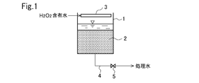
- a packed bed of activated carbon (hereinafter sometimes referred to as an activated carbon bed) 2 is formed as a hydrogen peroxide decomposition material in a container 1 having an open top.
- the hydrogen peroxide-containing water is supplied to the trough 3 provided at the upper part of the container 1, falls from the trough 3, passes through the activated carbon bed 2 by gravity, and hydrogen peroxide is decomposed during this time. .
- the treated water is taken out via the treated water extraction line 4 and the valve 5 connected to the bottom of the container 1.
- the hydrogen peroxide concentration in the treated water may be measured, and the diffusion step may be performed when hydrogen peroxide is detected.
- the gas accumulated in the activated carbon bed 2 may be detected by a sensor, and the gas diffusion process may be performed when the gas accumulation is detected.
- the diffusion step may be performed when the water passage duration reaches a preset time.
- the vibrator 6 is attached to the container 1 in FIG. In FIG. 2, the vibrator 6 is actuated when performing the diffusion process, and the activated carbon bed 2 is vibrated to promote gas emission.
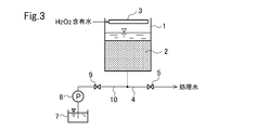
- the water in the tank 7 can be supplied to the line 4 via the pump 8, the valve 9, and the line 10.
- valve 5 when performing the diffusion process, the valve 5 is closed, the valve 9 is opened, the pump 8 is operated, and the water in the tank 7 is passed through the activated carbon bed 2 for a short time in an upward flow. Gas emission can be promoted.
- the amount of water in the backwash is very small (for example, about 3 to 10% of the volume of the activated carbon bed 2) so that the activated carbon is not held up.
- the water in the tank 7 is preferably treated water taken from the line 4 but may be raw water. Alternatively, the tank 7 may be omitted, and the raw water from the raw water supply line may be supplied to the container 1 as backwash water through the line 10.
- hydrogen peroxide-containing water is passed through the activated carbon bed 2 by gravity.
- the activated carbon bed 12 is formed in the sealed container 11, and hydrogen peroxide-containing water is supplied to the trough 14 by the pump 13 and is pressurized and passed through the activated carbon bed 12.
- the treated water is taken from the bottom of the container 11 through the line 15 and the valve 16.
- a gas discharge valve 17 is provided at the top of the container 11. In the water flow process, the gas discharge valve 17 is closed. In the diffusion process, the pump 13 is stopped and the gas discharge valve 17 is opened. The gas is released upward from the activated carbon bed 12, and the gas in the upper part of the container 11 is discharged out of the container 11 through the gas discharge valve 17.
- a vibrator or a backwash system may be provided as shown in FIGS.
Landscapes
- Life Sciences & Earth Sciences (AREA)
- Hydrology & Water Resources (AREA)
- Engineering & Computer Science (AREA)
- Environmental & Geological Engineering (AREA)
- Water Supply & Treatment (AREA)
- Chemical & Material Sciences (AREA)
- Organic Chemistry (AREA)
- Removal Of Specific Substances (AREA)
- Catalysts (AREA)
- Water Treatment By Sorption (AREA)
Abstract
Description
上部が開放した100Lの容器に石炭系活性炭(JIS篩による平均粒径10~32メッシュ)を50L充填した。
SV=5h-1とした実験例2において、放散工程を省略し(b=0)、通水工程のみを連続して行った。処理水の過酸化水素濃度の経時変化を表1に示す。
実験例2において、通水工程時間a=60min、通水停止による放散工程時間b=5secとし、a/b=720としたこと以外は同一条件にて過酸化水素含有水を処理した。処理水の過酸化水素濃度の経時変化を表1に示す。
実験例2において、通水工程時間a=60min、通水停止による放散工程時間b=20secとし、a/b=180としたこと以外は同一条件にて過酸化水素含有水を処理した。処理水の過酸化水素濃度の経時変化を表1に示す。
実験例2において、通水工程時間a=60min、通水停止による放散工程時間b=30secとし、a/b=120としたこと以外は同一条件にて過酸化水素含有水を処理した。処理水の過酸化水素濃度の経時変化を表1に示す。なお、これ以上の場合、水回収率が低下するため好ましくない。

SV=5h-1とした実験例2において、石炭系活性炭の代わりにヤシ殻活性炭(平均粒径10~32メッシュ)を用いたこと以外は実験例2と同様にして通水を行った。処理水の過酸化水素濃度の経時変化を表1に示す。
なお、本出願は、2011年12月5日付で出願された日本特許出願(特願2011-265819)に基づいており、その全体が引用により援用される。
Claims (6)
- 過酸化水素含有水を過酸化水素分解材の充填床に通水して過酸化水素を分解する過酸化水素含有水の処理方法において、
過酸化水素含有水を該充填床に下向流にて通水して過酸化水素を分解する処理工程と、
この通水を停止して該充填床内のガスを充填床の上方に放散させるガス放散工程とを交互に行うことを特徴とする過酸化水素含有水の処理方法。 - 請求項1において、前記過酸化水素分解材は石炭系活性炭であることを特徴とする過酸化水素含有水の処理方法。
- 請求項2において、通水SVが0.5~12h-1であることを特徴とする過酸化水素含有水の処理方法。
- 請求項1ないし3のいずれか1項において、前記ガス放散工程において、前記過酸化水素分解材の充填床のバックウォッシュ又は振動印加を行うことを特徴とする過酸化水素含有水の処理方法。
- 請求項1ないし4のいずれか1項において、前記処理工程の継続時間aとガス放散工程の継続時間bとの比a/bが120~360であることを特徴とする過酸化水素含有水の処理方法。
- 請求項1ないし5のいずれか1項において、前記充填床は密閉容器内に形成されており、
該容器の上部からガスを排出するガス排出弁が設けられており、
前記通水工程では該ガス排出弁を閉とし、前記ガス放散工程では該ガス排出弁を開とすることを特徴とする過酸化水素含有水の処理方法。
Priority Applications (2)
| Application Number | Priority Date | Filing Date | Title |
|---|---|---|---|
| KR1020147013048A KR20140109366A (ko) | 2011-12-05 | 2012-12-04 | 과산화수소 함유수의 처리 방법 |
| JP2013548232A JP5910635B2 (ja) | 2011-12-05 | 2012-12-04 | 過酸化水素含有水の処理方法 |
Applications Claiming Priority (2)
| Application Number | Priority Date | Filing Date | Title |
|---|---|---|---|
| JP2011265819 | 2011-12-05 | ||
| JP2011-265819 | 2011-12-05 |
Publications (1)
| Publication Number | Publication Date |
|---|---|
| WO2013084855A1 true WO2013084855A1 (ja) | 2013-06-13 |
Family
ID=48574222
Family Applications (1)
| Application Number | Title | Priority Date | Filing Date |
|---|---|---|---|
| PCT/JP2012/081316 Ceased WO2013084855A1 (ja) | 2011-12-05 | 2012-12-04 | 過酸化水素含有水の処理方法 |
Country Status (3)
| Country | Link |
|---|---|
| JP (1) | JP5910635B2 (ja) |
| KR (1) | KR20140109366A (ja) |
| WO (1) | WO2013084855A1 (ja) |
Cited By (1)
| Publication number | Priority date | Publication date | Assignee | Title |
|---|---|---|---|---|
| JP2017093799A (ja) * | 2015-11-24 | 2017-06-01 | 株式会社稲本製作所 | 過酸化水素分解装置を備えた連続洗濯装置 |
Families Citing this family (2)
| Publication number | Priority date | Publication date | Assignee | Title |
|---|---|---|---|---|
| KR101885830B1 (ko) * | 2016-06-27 | 2018-09-11 | 삼성엔지니어링 주식회사 | 과산화수소와 유기물의 동시 제거 수처리 방법 및 장치 |
| KR102091728B1 (ko) * | 2019-08-27 | 2020-05-29 | 정영남 | 활성탄을 이용하여 황산폐산 내 과산화수소를 제거하는 체류형 연속식 분해조장치 |
Citations (4)
| Publication number | Priority date | Publication date | Assignee | Title |
|---|---|---|---|---|
| JPH07171560A (ja) * | 1991-07-08 | 1995-07-11 | Bethlehem Steel Corp | 流体から過酸化水素を除去する活性炭フィルター装置及び方法 |
| JPH07171561A (ja) * | 1993-12-21 | 1995-07-11 | Japan Organo Co Ltd | 粒状活性炭充填塔による過酸化水素の除去方法 |
| JP2001121144A (ja) * | 1999-10-26 | 2001-05-08 | Kurita Water Ind Ltd | Cmp排水の処理装置 |
| WO2010008072A1 (ja) * | 2008-07-18 | 2010-01-21 | 株式会社クレハ | 酸化剤含有排水処理剤、酸化剤含有排水処理方法、及び酸化剤含有排水処理装置、並びに有機溶媒精製剤、有機溶媒精製方法、及び有機溶媒精製装置 |
Family Cites Families (2)
| Publication number | Priority date | Publication date | Assignee | Title |
|---|---|---|---|---|
| JPH0839054A (ja) * | 1994-07-27 | 1996-02-13 | Kurita Water Ind Ltd | 過酸化水素の分解方法 |
| JPH0839078A (ja) * | 1994-08-03 | 1996-02-13 | Kurita Water Ind Ltd | 過酸化水素の分解方法 |
-
2012
- 2012-12-04 WO PCT/JP2012/081316 patent/WO2013084855A1/ja not_active Ceased
- 2012-12-04 JP JP2013548232A patent/JP5910635B2/ja active Active
- 2012-12-04 KR KR1020147013048A patent/KR20140109366A/ko not_active Ceased
Patent Citations (4)
| Publication number | Priority date | Publication date | Assignee | Title |
|---|---|---|---|---|
| JPH07171560A (ja) * | 1991-07-08 | 1995-07-11 | Bethlehem Steel Corp | 流体から過酸化水素を除去する活性炭フィルター装置及び方法 |
| JPH07171561A (ja) * | 1993-12-21 | 1995-07-11 | Japan Organo Co Ltd | 粒状活性炭充填塔による過酸化水素の除去方法 |
| JP2001121144A (ja) * | 1999-10-26 | 2001-05-08 | Kurita Water Ind Ltd | Cmp排水の処理装置 |
| WO2010008072A1 (ja) * | 2008-07-18 | 2010-01-21 | 株式会社クレハ | 酸化剤含有排水処理剤、酸化剤含有排水処理方法、及び酸化剤含有排水処理装置、並びに有機溶媒精製剤、有機溶媒精製方法、及び有機溶媒精製装置 |
Cited By (1)
| Publication number | Priority date | Publication date | Assignee | Title |
|---|---|---|---|---|
| JP2017093799A (ja) * | 2015-11-24 | 2017-06-01 | 株式会社稲本製作所 | 過酸化水素分解装置を備えた連続洗濯装置 |
Also Published As
| Publication number | Publication date |
|---|---|
| JPWO2013084855A1 (ja) | 2015-04-27 |
| KR20140109366A (ko) | 2014-09-15 |
| JP5910635B2 (ja) | 2016-04-27 |
Similar Documents
| Publication | Publication Date | Title |
|---|---|---|
| TWI485114B (zh) | Wastewater treatment system containing hydrogen peroxide | |
| KR20110053946A (ko) | 유기물 함유수의 처리 방법 및 장치 | |
| CN106746034A (zh) | 一种两级梯度臭氧催化流化床深度处理生化尾水的装置及方法 | |
| CN207774892U (zh) | 废水处理用臭氧接触反应装置 | |
| JP5910635B2 (ja) | 過酸化水素含有水の処理方法 | |
| CN206512041U (zh) | 一种两级梯度臭氧催化流化床深度处理生化尾水的装置 | |
| CN101497014A (zh) | 新型光催化臭氧化流化床反应装置及水处理方法 | |
| JP4860008B1 (ja) | 過酸化水素分解装置及び過酸化水素の分解方法 | |
| JP5971257B2 (ja) | 充填塔の逆洗方法 | |
| CN106915840A (zh) | 一种一体化难降解废水处理及回用装置和污水处理方法 | |
| CN116670079A (zh) | 通过与臭氧添加联用的活性炭吸附来处理水的方法以及实施这种方法的设备 | |
| CN210795890U (zh) | 臭氧催化氧化移动床反应装置 | |
| CN100515944C (zh) | 从含氰、含硫氰酸盐溶液中再生氰化钠的方法 | |
| CN115724519A (zh) | 反应器、臭氧催化氧化系统以及废水处理方法 | |
| JP4511881B2 (ja) | 排水処理方法 | |
| CN219326620U (zh) | 一种基于多级活性炭的连续流水处理系统 | |
| JP2003190972A (ja) | 過酸化水素含有排水処理装置 | |
| CN201148386Y (zh) | 臭氧/活性炭一体化废水处理装置 | |
| CN204702555U (zh) | 一种组合式废液高效催化氧化反应器 | |
| JP5779408B2 (ja) | 過酸化物含有水の処理方法及び処理装置 | |
| CN209128117U (zh) | 一种反渗透浓水有机物和氨氮同时去除的装置 | |
| CN103357258B (zh) | 一种基于二氧化碳自由基的含氧气体的除氧方法 | |
| JP2005246327A (ja) | 排水処理装置 | |
| JP2000093740A (ja) | 窒素酸化物濃度が変動する排ガスの脱硝方法 | |
| CN223921206U (zh) | 基于粉末型催化剂的臭氧催化氧化废水处理装置 |
Legal Events
| Date | Code | Title | Description |
|---|---|---|---|
| 121 | Ep: the epo has been informed by wipo that ep was designated in this application |
Ref document number: 12854845 Country of ref document: EP Kind code of ref document: A1 |
|
| ENP | Entry into the national phase |
Ref document number: 2013548232 Country of ref document: JP Kind code of ref document: A |
|
| ENP | Entry into the national phase |
Ref document number: 20147013048 Country of ref document: KR Kind code of ref document: A |
|
| NENP | Non-entry into the national phase |
Ref country code: DE |
|
| 122 | Ep: pct application non-entry in european phase |
Ref document number: 12854845 Country of ref document: EP Kind code of ref document: A1 |