WO2013084677A1 - マルチコア光ファイバ接続構造体およびマルチコア光ファイバ接続構造体製造方法 - Google Patents
マルチコア光ファイバ接続構造体およびマルチコア光ファイバ接続構造体製造方法 Download PDFInfo
- Publication number
- WO2013084677A1 WO2013084677A1 PCT/JP2012/079537 JP2012079537W WO2013084677A1 WO 2013084677 A1 WO2013084677 A1 WO 2013084677A1 JP 2012079537 W JP2012079537 W JP 2012079537W WO 2013084677 A1 WO2013084677 A1 WO 2013084677A1
- Authority
- WO
- WIPO (PCT)
- Prior art keywords
- optical fiber
- core optical
- core
- central axis
- face
- Prior art date
Links
Images

Classifications
-
- G—PHYSICS
- G02—OPTICS
- G02B—OPTICAL ELEMENTS, SYSTEMS OR APPARATUS
- G02B6/00—Light guides; Structural details of arrangements comprising light guides and other optical elements, e.g. couplings
- G02B6/24—Coupling light guides
- G02B6/36—Mechanical coupling means
- G02B6/38—Mechanical coupling means having fibre to fibre mating means
- G02B6/3807—Dismountable connectors, i.e. comprising plugs
- G02B6/3873—Connectors using guide surfaces for aligning ferrule ends, e.g. tubes, sleeves, V-grooves, rods, pins, balls
- G02B6/3885—Multicore or multichannel optical connectors, i.e. one single ferrule containing more than one fibre, e.g. ribbon type
-
- G—PHYSICS
- G02—OPTICS
- G02B—OPTICAL ELEMENTS, SYSTEMS OR APPARATUS
- G02B6/00—Light guides; Structural details of arrangements comprising light guides and other optical elements, e.g. couplings
- G02B6/24—Coupling light guides
- G02B6/36—Mechanical coupling means
- G02B6/3628—Mechanical coupling means for mounting fibres to supporting carriers
- G02B6/3648—Supporting carriers of a microbench type, i.e. with micromachined additional mechanical structures
- G02B6/3652—Supporting carriers of a microbench type, i.e. with micromachined additional mechanical structures the additional structures being prepositioning mounting areas, allowing only movement in one dimension, e.g. grooves, trenches or vias in the microbench surface, i.e. self aligning supporting carriers
-
- G—PHYSICS
- G02—OPTICS
- G02B—OPTICAL ELEMENTS, SYSTEMS OR APPARATUS
- G02B6/00—Light guides; Structural details of arrangements comprising light guides and other optical elements, e.g. couplings
- G02B6/24—Coupling light guides
- G02B6/36—Mechanical coupling means
- G02B6/38—Mechanical coupling means having fibre to fibre mating means
- G02B6/3807—Dismountable connectors, i.e. comprising plugs
- G02B6/381—Dismountable connectors, i.e. comprising plugs of the ferrule type, e.g. fibre ends embedded in ferrules, connecting a pair of fibres
- G02B6/3818—Dismountable connectors, i.e. comprising plugs of the ferrule type, e.g. fibre ends embedded in ferrules, connecting a pair of fibres of a low-reflection-loss type
- G02B6/3822—Dismountable connectors, i.e. comprising plugs of the ferrule type, e.g. fibre ends embedded in ferrules, connecting a pair of fibres of a low-reflection-loss type with beveled fibre ends
-
- G—PHYSICS
- G02—OPTICS
- G02B—OPTICAL ELEMENTS, SYSTEMS OR APPARATUS
- G02B6/00—Light guides; Structural details of arrangements comprising light guides and other optical elements, e.g. couplings
- G02B6/24—Coupling light guides
- G02B6/42—Coupling light guides with opto-electronic elements
- G02B6/4201—Packages, e.g. shape, construction, internal or external details
- G02B6/4219—Mechanical fixtures for holding or positioning the elements relative to each other in the couplings; Alignment methods for the elements, e.g. measuring or observing methods especially used therefor
- G02B6/422—Active alignment, i.e. moving the elements in response to the detected degree of coupling or position of the elements
- G02B6/4221—Active alignment, i.e. moving the elements in response to the detected degree of coupling or position of the elements involving a visual detection of the position of the elements, e.g. by using a microscope or a camera
- G02B6/4224—Active alignment, i.e. moving the elements in response to the detected degree of coupling or position of the elements involving a visual detection of the position of the elements, e.g. by using a microscope or a camera using visual alignment markings, e.g. index methods
-
- Y—GENERAL TAGGING OF NEW TECHNOLOGICAL DEVELOPMENTS; GENERAL TAGGING OF CROSS-SECTIONAL TECHNOLOGIES SPANNING OVER SEVERAL SECTIONS OF THE IPC; TECHNICAL SUBJECTS COVERED BY FORMER USPC CROSS-REFERENCE ART COLLECTIONS [XRACs] AND DIGESTS
- Y10—TECHNICAL SUBJECTS COVERED BY FORMER USPC
- Y10T—TECHNICAL SUBJECTS COVERED BY FORMER US CLASSIFICATION
- Y10T29/00—Metal working
- Y10T29/49—Method of mechanical manufacture
- Y10T29/49826—Assembling or joining
Definitions
- the present invention relates to a multi-core optical fiber connection structure and a method for manufacturing the multi-core optical fiber connection structure.
- PC Physical-Contact
- the inventor found the following problems. That is, in the case of a multi-core optical fiber having a plurality of cores extending along the central axis in a common clad, since the core exists at a position other than the center on the end face, the above-mentioned PC coupling is performed for each of the plurality of cores. It is difficult to apply. No optical connection between multi-core optical fibers has been observed so far in consideration of reflection at the connection.
- the present invention has been made in order to solve the above-described problems, and multicore light capable of reducing reflection at a connection portion in which end faces of the first and second multicore optical fibers are connected to each other.
- the object is to provide a fiber connection structure.
- a multi-core optical fiber connection structure includes, as a first aspect, a first multi-core optical fiber having a plurality of cores extending along a first central axis in a common cladding, and a second central axis.
- the core arrangement and the core interval of the first multicore optical fiber on the plane perpendicular to the first central axis substantially coincide with the core arrangement and the core interval of the second multicore optical fiber on the plane perpendicular to the second central axis. ing.
- At least one end face of the first multi-core optical fiber is inclined with respect to a plane perpendicular to the first central axis.
- at least one end face of the second multi-core optical fiber is inclined with respect to a plane perpendicular to the second central axis.
- the inclined end surfaces of the first and second multi-core optical fibers face each other with the first central axis and the second central axis maintained substantially parallel to each other.
- First and second multi-core optical fibers are disposed.
- each of the cores of the first multicore optical fiber and each of the cores of the second multicore optical fiber are optically coupled in a state of being in a one-to-one correspondence.
- the inclined end face of the first multi-core optical fiber and the inclined end face of the second multi-core optical fiber are each composed of a core corresponding to one to one. It is preferable to face each other so that the variation in the connection loss between the cores is minimized.
- the inclined end face of the first multicore optical fiber and the inclined end face of the second multicore optical fiber are in one-to-one correspondence. It is preferable to face each other so as to minimize the variation in the core interval of the set of cores associated with each other.
- the inclined end surface of the first multi-core optical fiber is 5 degrees with respect to a plane perpendicular to the first central axis.
- the inclination is preferably in the range of ⁇ 11 degrees.
- the inclined end face of the second multi-core optical fiber is preferably inclined within a range of 5 to 11 degrees with respect to a plane perpendicular to the second central axis.
- the first multi-core optical fiber has a position of each core in a core array on a plane perpendicular to the first central axis. It is preferable to have a first marker for identification. Similarly, it is preferable that the second multi-core optical fiber also has a second marker for specifying the position of each core in the core array on the plane perpendicular to the second central axis.
- the position of the first marker on the inclined end surface of the first multicore optical fiber includes the intersection of the inclined end surface of the first multicore optical fiber and the first central axis and is perpendicular to the first central axis. Rather than the other end face of the first multi-core optical fiber.
- the position of the second marker on the inclined end surface of the second multi-core optical fiber is a second reference plane that includes the intersection of the inclined end surface of the second multi-core optical fiber and the second central axis and is perpendicular to the second central axis. Rather than the other end face of the second multi-core optical fiber.
- a core interval of a set of cores each corresponding one-to-one It is possible to easily minimize the variation of the above.
- the multi-core optical fiber connection structure further includes a first ferrule, a second ferrule, and a sleeve. good.
- the first ferrule is fixed to one end portion of the first multicore optical fiber in a state where one end portion of the first multicore optical fiber including the inclined end surface is inserted.
- the second ferrule is fixed to one end portion of the second multicore optical fiber in a state where one end portion of the second multicore optical fiber including the inclined end face is inserted.
- the sleeve positions the first ferrule and the second ferrule.
- the multi-core optical fiber connection structure is provided for positioning the first multi-core optical fiber and the second multi-core optical fiber.
- a groove member may be further provided.
- the return loss of light on the inclined end face of the first multicore optical fiber is 30 dB or more.
- the return loss of light at the inclined end surface of the second multi-core optical fiber is preferably 30 dB or more.
- the positions of the cores of the first multicore optical fiber and the cores of the second multicore optical fiber that are associated one-to-one The amount of deviation is preferably 1.6 ⁇ m or less.
- the connection between the core of the first multicore optical fiber and the core of the second multicore optical fiber that are associated one-to-one The loss is preferably 0.4 dB or less.
- at least a part of the inclined end surface of the first multicore optical fiber is inclined to the second multicore optical fiber. It is preferable to contact the end face.
- a method for manufacturing a multicore optical fiber connection structure manufactures a multicore optical fiber connection structure according to at least one of the first to eleventh aspects.
- the first multi-core optical fiber has a plurality of cores extending along the first central axis in a common cladding, and at least one end face is inclined with respect to a plane perpendicular to the first central axis.
- the second multi-core optical fiber has a plurality of cores extending along the second central axis in a common cladding, and at least one end face is inclined with respect to a plane perpendicular to the second central axis.
- the inclined end surface of the first multicore optical fiber and the inclined end surface of the second multicore optical fiber face each other in a state where the first central axis and the second central axis are substantially parallel.
- the first and second multi-core optical fibers are disposed so as to meet each other.
- each of the cores of the first multicore optical fiber and each of the cores of the second multicore optical fiber is associated with each other in a one-to-one correspondence, The relative positions of the inclined end faces of the first and second multi-core optical fibers are adjusted so that the variation in the inter-core connection loss is minimized.
- the inclined end face of the first multicore optical fiber is in contact with the inclined end face of the second multicore optical fiber.
- the multi-core optical fiber connection structure according to the present invention, it is possible to reduce reflection at the connection portion between the multi-core optical fibers.
- Multi-core optical fiber connection structure 10 ... 1st multi-core optical fiber, 11 ... Core, 12 ... Cladding, 13 ... Marker, 14 ... End surface, 20 ... 2nd multi-core optical fiber, 21 ... Core, 22 ... Cladding , 23 ... marker, 24 ... end face, 30 ... first ferrule, 40 ... second ferrule, 50 ... sleeve, 60 ... groove member, 70 ... lid member, AX1 ... first central axis, AX2 ... second central axis.
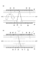
- FIG. 1 is a diagram illustrating a configuration of one multicore optical fiber (first multicore optical fiber) 10 applicable to the multicore optical fiber connection structure 1 according to the first embodiment.
- FIG. 1A is a view of the multi-core optical fiber 10 viewed from the direction along the central axis AX1.
- FIGS. 1B and 1C are views of the multi-core optical fiber 10 viewed from two directions perpendicular to the direction along the central axis AX1 and orthogonal to each other.
- the multi-core optical fiber 10 has a plurality of cores 11 extending along the central axis AX1 in a common clad 12.
- Each core 11 has a refractive index higher than that of the clad 12 and can guide light.
- a single core 11 is present at the center position in the circular cross section perpendicular to the central axis AX1 of the multi-core optical fiber 10, and this is the center.
- a ferrule 30 is fixed to the end of the multi-core optical fiber 10 including the end face 14 in a state where the end is inserted.
- the end face 14 of the multi-core optical fiber 10 and the end face of the ferrule 30 are on a common plane and are inclined with respect to a plane perpendicular to the central axis AX1.
- the inclination angle is, for example, 8 degrees.
- Such a multi-core optical fiber 10 and a ferrule 30 are manufactured as follows.
- the clad 12 is exposed by removing a certain range of the coating layer on one end side of the multi-core optical fiber 10. Then, this end portion where the clad 12 is exposed is inserted into the ferrule 30.
- the adhesive is injected into the ferrule 30 with the one end side of the multi-core optical fiber 10 slightly protruding from the ferrule 30, so that both are fixed to each other.
- the end surfaces of the multi-core optical fiber 10 and the ferrule 30 are polished to form an end surface 14 that is inclined with respect to a surface perpendicular to the central axis AX1.
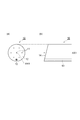
- FIG. 2 is a diagram showing a configuration of the multi-core optical fiber connection structure 1 according to the first embodiment.
- the multi-core optical fiber connection structure 1 includes the multi-core optical fiber (first multi-core optical fiber) 10 and the ferrule 30 described above, and also includes the multi-core optical fiber (second multi-core optical fiber) 20 and the ferrule 40 having the same configuration as these.
- a sleeve 50 is also provided. The inner diameter of the sleeve 50 is slightly larger than the outer diameter of the ferrules 30 and 40.
- the inclined end surface 14 side is inserted into the sleeve 50.
- the inclined end surface 24 side is inserted into the sleeve 50.
- the multi-core optical fiber 10 and the multi-core optical fiber 20 are arranged so that the central axes AX1 and AX2 are parallel to each other and the end faces 14 and 24 face each other.
- Each of the cores 11 of the multicore optical fiber 10 and each of the cores 21 of the multicore optical fiber 20 are optically coupled to each other in a one-to-one correspondence.
- the multi-core optical fiber connection structure 1 having the above-described structure is manufactured as follows. That is, as shown in FIG. 2A, the end of the multi-core optical fiber 10 including the inclined end surface 14 from one open end of the sleeve 50 together with the ferrule 30 fixed to the end 50. Inserted inside. Further, the end portion of the multi-core optical fiber 20 including the inclined end surface 24 is inserted into the sleeve 50 from the other open end of the sleeve 50 together with the ferrule 40 fixed to the end portion.
- both or one of the multi-core optical fibers 10 and 20 is rotated so that the contact area between the end face 14 of the multi-core optical fiber 10 and the end face 24 of the multi-core optical fiber 20 is increased (FIG. 2A).
- the end surface 14 of the multi-core optical fiber 10 and the end surface 24 of the multi-core optical fiber 20 are connected.
- the multi-core optical fiber connection structure 1 in which the position of the core 11 in the multi-core optical fiber 10 to be optically coupled one-to-one and the position of the core 21 in the multi-core optical fiber 20 coincide with each other is obtained (FIG. 2). (See (b)).
- the end surface 14 of the multi-core optical fiber 10 and the end surface of the second multi-core optical fiber 20 regardless of whether the end surfaces 14 and 24 are in contact with each other or the end surfaces 14 and 24 are not in contact with each other partially or entirely. 24 are preferably facing each other so as to minimize the variation in the inter-core connection loss of the pair of cores 11 and 21 that are in one-to-one correspondence.
- the amount of misalignment between the core 11 and the core 21 corresponding one-to-one is preferably 1.6 ⁇ m or less.
- the connection loss of the core 11 and the core 21 corresponding to one to one is 0.4 dB or less.
- the end face 14 of the multicore optical fiber 10 and the end face 24 of the second multicore optical fiber 20 face each other so as to minimize the variation in the core interval between the pairs of cores associated one to one.
- the end face 14 of the multi-core optical fiber 10 and the end face 24 of the multi-core optical fiber 20 is not maximized, and there is a slight gap between the end face 14 and the end face 24, the multi-core light Reflection at the connection between the fibers 10 and 20 is effectively reduced.
- the end face 14 has an inclination of 8 degrees with respect to the plane perpendicular to the central axis AX1, while the end face 24 has an inclination of 8 degrees with respect to the plane perpendicular to the central axis AX2.
- the multi-core optical fiber connection structure 1 (FIG. 2B) includes the multi-core optical fibers 10 and 20, the ferrules 30 and 40, and the sleeve 50.
- this connector is practical, has a small amount of reflected return light (that is, a large amount of return loss), and can connect multiple cores with low loss. Can be realized.
- the inclination angle of the end face of the multicore optical fiber is about 8 degrees with respect to the plane perpendicular to the central axis.
- the return loss can be further increased.
- the precision of the core alignment by adjusting so that an end surface contact area may become large with the cross-sectional area increase of an oblique end surface can be improved.
- the amount of polishing for forming an end face with a large inclination angle increases.
- practical problems such as an increased possibility of breakage of the tip portion of the oblique end face at the time of butting increase.
- the angle of the oblique end face is desirably about 8 ⁇ 3 degrees (in the range of 5 degrees to 11 degrees) from the viewpoint of achieving both characteristics such as return loss and practicality.
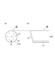
- FIG. 3 is a diagram illustrating a configuration of one multicore optical fiber (first multicore optical fiber) 10 applied to the multicore optical fiber connection structure 2 according to the second embodiment.
- FIG. 3A is a view of the multi-core optical fiber 10 viewed from the direction along the central axis AX1.
- FIG. 3B is a view of the multi-core optical fiber 10 viewed from a direction perpendicular to the central axis AX1.
- the multi-core optical fiber 10 has a plurality of cores 11 extending along the central axis AX1 in a common clad 12.
- Each core 11 has a refractive index higher than that of the clad 12 and can guide light.
- a single core 11 is present at the center position in the circular cross section perpendicular to the central axis AX1 of the multi-core optical fiber 10, and this is the center.
- the multi-core optical fiber 10 has a marker 13 (marker for specifying the position of each core in the core array) 13 for identifying the core array orientation.
- the marker 13 extends along the central axis AX1.
- the marker 13 in the circular cross section perpendicular to the central axis AX1 of the multi-core optical fiber 10, the marker 13 is more than the circle in which the six cores 11 exist on the circumference. It is outside and is arranged at a position equidistant from two adjacent cores of the six cores 11.
- the end face 14 of the multicore optical fiber 10 is inclined with respect to a plane perpendicular to the central axis AX1.
- the inclination angle is, for example, 8 degrees.
- Such a multi-core optical fiber 10 is manufactured as follows. A coating layer in a certain range on one end side of the multi-core optical fiber 10 is removed to expose the cladding 12, and the end face of the multi-core optical fiber 10 is cut obliquely so that the end face 14 protrudes on the side where the marker 13 is present.
- the oblique cutting method include a method of giving a fine scratch to a portion that becomes a starting point of cutting in a state where the multi-core optical fiber is twisted, and a method of using laser light whose irradiation direction and scanning direction are controlled.
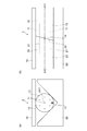
- FIG. 4 is a diagram showing a configuration of the other multi-core optical fiber (second multi-core optical fiber) 20 applied to the multi-core optical fiber connection structure 2 according to the second embodiment.
- FIG. 4A is a view of the multi-core optical fiber 20 viewed from the direction along the central axis AX2.
- FIG. 4B is a view of the multi-core optical fiber 20 viewed from a direction perpendicular to the central axis AX2.
- the multicore optical fiber 20 has substantially the same configuration as the multicore optical fiber 10.
- the multi-core optical fiber 20 has a plurality of cores 21 and markers 23 extending along the central axis AX2 in a common cladding 22, and an end face 24 that is inclined with respect to a plane perpendicular to the central axis AX2.
- the relationship between the orientation of the inclination of the end faces of each of the multi-core optical fiber 10 and the multi-core optical fiber 20 and the position of the marker is opposite to each other. That is, in the multicore optical fiber 10, the end face 14 protrudes toward the multicore optical fiber 20 on the side where the marker 13 exists. On the contrary, in the multicore optical fiber 20, the end face 24 protrudes toward the multicore optical fiber 10 on the side opposite to the side where the marker 23 exists.
- FIG. 5 is a diagram showing a configuration of the multi-core optical fiber connection structure 2 according to the second embodiment.
- 5A shows a cross section perpendicular to the central axis AX1
- FIG. 5B shows a cross section including the central axes AX1 and AX2.
- the multi-core optical fiber connection structure 2 includes the groove member 60 and the lid member 70 in addition to the multi-core optical fiber 10 and the multi-core optical fiber 20 as described above.
- the groove member 60 has a V-groove for positioning the multi-core optical fiber 10 and the multi-core optical fiber 20.
- the lid member 70 is placed on the multi-core optical fiber 10 and the multi-core optical fiber 20 positioned by the V-groove of the groove member 60, and functions so that they do not come off the V-groove.
- both or one of the multi-core optical fibers 10 and 20 is rotated so that the contact area between the end face 14 of the multi-core optical fiber 10 and the end face 24 of the multi-core optical fiber 20 is increased.
- the adhesive is injected into the gap between the multi-core optical fiber 10, the multi-core optical fiber 20, the V-groove of the groove member 60 and the lid member 70, and these components are fixed by fixing the adhesive.
- the multi-core optical fiber connection structure 2 is manufactured as described above.
- the multi-core optical fiber connection structure 2 optically connects the multi-core optical fiber 10 and the multi-core optical fiber 20 by a mechanical splice.
- the contact area between the end surface 14 of the multicore optical fiber 10 and the end surface 24 of the multicore optical fiber 20 is not maximized, and a slight gap is generated between the end surface 14 and the end surface 24. Even so, reflection at the connection between the multi-core optical fibers 10 and 20 is effectively reduced. That is, in the present embodiment, the end surface 14 has an inclination of 8 degrees with respect to the surface surrounding perpendicular to the central axis AX1, while the end surface 24 has an inclination of 8 degrees with respect to the surface perpendicular to the central axis AX2.
- the end surfaces of the opposing multicore optical fibers are in contact with each other, and at the opposite end (for example, the right end in the direction in which three cores are arranged side by side in FIGS. 3A and 4A), Consider a case where a gap of 20 ⁇ m is generated between the end faces.
- the cladding diameter of the multi-core optical fiber is 125 ⁇ m
- the positional deviation in the end faces is about a maximum.
- this positional shift amount corresponds to a connection loss of about 0.4 dB.
- the present invention is not limited to the above embodiment, and various modifications can be made.
- seven cores are arranged in a triangular lattice shape, but the number of cores and the core arrangement of the multi-core optical fiber are not limited to this.
- the number of cores may be 6 or less, or 8 or more.
- the core arrangement may be in various forms such as a square lattice arrangement or an arrangement on the same circumference.
- one marker is optically recognizable at the end face, but the number, form and arrangement of the markers are not limited to this. Various modifications are possible, such as arranging two or more markers so that oblique end face formation is easy.
- single-core multicore optical fibers are connected to each other, but the present invention is also applicable to collective connection of a plurality of multicore optical fibers. Further, it can be applied not only to mutual connection of multi-core optical fibers but also to connection of multi-core optical fibers and other optical components. Also in this case, the effect of increasing the return loss of the multi-core optical fiber is expected.
Landscapes
- Physics & Mathematics (AREA)
- General Physics & Mathematics (AREA)
- Optics & Photonics (AREA)
- Chemical & Material Sciences (AREA)
- Crystallography & Structural Chemistry (AREA)
- Mechanical Coupling Of Light Guides (AREA)
- Optical Couplings Of Light Guides (AREA)
- Optical Fibers, Optical Fiber Cores, And Optical Fiber Bundles (AREA)
Abstract
マルチコア光ファイバ接続構造体は、傾斜した端面を有する第1マルチコア光ファイバと、傾斜した端面を有する第2マルチコア光ファイバを備える。傾斜した端面同士が対面し合った状態で、第1マルチコア光ファイバのコアそれぞれと、第2マルチコア光ファイバのコアそれぞれは、一対一に光学的に結合している。傾斜した端面同士の対面状態は、それぞれが一対一に対応付けられたコアからなる組のコア間隔のバラツキが最小になるように調整されている。
Description
本発明は、マルチコア光ファイバ接続構造体およびマルチコア光ファイバ接続構造体の製造方法に関するものである。
通常の単一コア光ファイバ同士を光学的に端面接続する方法としてPC(Physical Contact)結合が知られている。PC結合により接続部での反射低減を図るには、一方の単一コア光ファイバのコアの端面と他方の単一コア光ファイバのコアの端面とを互いに接触させる必要がある。単一コア光ファイバの場合に、端面において中心に唯一つのコアが存在するので、各々の光ファイバの端面において中心部が頂点となるように端面を凸状に研磨して、各々の光ファイバの端面を対向接触させればよい。
発明者は、従来技術について検討した結果、以下のような課題を発見した。すなわち、中心軸に沿って延在する複数のコアを共通のクラッド中に有するマルチコア光ファイバの場合、端面において中心以外の位置にもコアが存在するので、複数のコアそれぞれについて上記のPC結合を適用することは困難である。マルチコア光ファイバ同士の光学的接続について接続部での反射に配慮したものは今まで見られなかった。
本発明は、上述のような課題を解決するためになされたものであり、第1および第2マルチコア光ファイバそれぞれの端面が互いに接続されてなる接続部での反射低減を図ることができるマルチコア光ファイバ接続構造体を提供することを目的としている。
本発明に係るマルチコア光ファイバ接続構造体は、第1の態様として、第1中心軸に沿って延在する複数のコアを共通のクラッド中に有する第1マルチコア光ファイバと、第2中心軸に沿って延在する複数のコアを共通のクラッド中に有する第2マルチコア光ファイバとを備える。なお、第1中心軸に垂直な面上における第1マルチコア光ファイバのコア配列およびコア間隔は、第2中心軸に垂直な面上における第2マルチコア光ファイバのコア配列およびコア間隔と略一致している。
第1の態様において、第1マルチコア光ファイバの少なくとも一方の端面は、第1中心軸に垂直な面に対して傾斜している。また、第2マルチコア光ファイバの少なくとも一方の端面は、第2中心軸に垂直な面に対して傾斜している。特に、第1の態様では、第1中心軸と第2中心軸とが実質的に平行に維持された状態で第1および第2マルチコア光ファイバの傾斜した端面同士が互いに対面し合うように、第1および第2マルチコア光ファイバが配置されている。また、第1マルチコア光ファイバのコアそれぞれと第2マルチコア光ファイバのコアそれぞれとが1対1に対応付けられた状態で光学的に結合している。
上記第1の態様に適用可能な第2の態様として、第1マルチコア光ファイバの傾斜した端面と第2マルチコア光ファイバの傾斜した端面は、それぞれが一対一に対応付けられたコアからなる組のコア間接続損失のバラツキが最小になるよう対面し合うのが好ましい。
上記第1および第2の態様のうち少なくとも何れかの態様に適用可能な第3の態様として、第1マルチコア光ファイバの傾斜した端面と第2マルチコア光ファイバの傾斜した端面は、それぞれが一対一に対応付けられたコアからなる組のコア間隔のバラツキが最小になるよう対面し合うのが好ましい。
さらに、上記第1~第3の態様のうち少なくとも何れかの態様に適用可能な第4の態様として、第1マルチコア光ファイバの傾斜した端面は、第1中心軸に垂直な面対して5度~11度の範囲で傾斜しているのが好ましい。同様に、第2マルチコア光ファイバの傾斜した端面も、第2中心軸に垂直な面に対して5度~11度の範囲で傾斜しているのが好ましい。
上記第1~第4の態様のうち少なくとも何れかの態様に適用可能な第5の態様として、第1マルチコア光ファイバは、第1中心軸に垂直な面上のコア配列における各コアの位置を特定するための第1マーカを有するのが好ましい。同様に、第2マルチコア光ファイバも、第2中心軸に垂直な面上のコア配列における各コアの位置を特定するための第2マーカを有するのが好ましい。特に、第1マルチコア光ファイバの傾斜した端面における第1マーカの位置は、第1マルチコア光ファイバの傾斜した端面と第1中心軸との交点を含みかつ第1中心軸に垂直な第1基準面よりも当該第1マルチコア光ファイバの他方の端面から遠い端面領域内に存在する。一方、第2マルチコア光ファイバの傾斜した端面における第2マーカの位置は、第2マルチコア光ファイバの傾斜した端面と第2中心軸との交点を含みかつ第2中心軸に垂直な第2基準面よりも当該第2マルチコア光ファイバの他方の端面に近い端面領域内に存在する。この場合、第1マーカと第2マーカと一致させるように第1および第2マルチコア光ファイバの傾斜した端面同士を対面させることにより、それぞれが一対一に対応付けられたコアからなる組のコア間隔のバラツキを、簡単に最小にすることが可能になる。
上記第1~第5の態様のうち少なくとも何れかの態様に適用可能な第6の態様として、当該マルチコア光ファイバ接続構造体は、第1フェルールと、第2フェルールと、スリーブを更に備えても良い。第1フェルールは、傾斜した端面を含む第1マルチコア光ファイバの一方の端部が挿入された状態で、第1マルチコア光ファイバの一方の端部に固定される。第2フェルールは、傾斜した端面を含む第2マルチコア光ファイバの一方の端部が挿入された状態で、第2マルチコア光ファイバの一方の端部に固定される。スリーブは、第1フェルールおよび第2フェルールを位置決めする。
上記第1~第6の態様のうち少なくとも何れかの態様に適用可能な第7の態様として、当該マルチコア光ファイバ接続構造体は、第1マルチコア光ファイバおよび第2マルチコア光ファイバを位置決めするための溝部材を更に備えてもよい。
上記第1~第7の態様のうち少なくとも何れかの態様に適用可能な第8の態様として、第1マルチコア光ファイバの傾斜した端面における光の反射減衰量は30dB以上であるのが好ましい。同様に、第2マルチコア光ファイバの傾斜した端面における光の反射減衰量も30dB以上であるのが好ましい。なお、反射減衰量(ORL: Optical Return Loss)は、光部品に入射される光のパワー(入射光パワー)と、該光部品から光源側に戻る光のパワー(反射戻り光パワー)の比により、以下のように定義される。
ORL=-10・Log(反射戻り光パワー/入射光パワー)
したがって、反射減衰量の増大は、反射戻り光の光量の減少を意味する。
ORL=-10・Log(反射戻り光パワー/入射光パワー)
したがって、反射減衰量の増大は、反射戻り光の光量の減少を意味する。
上記第1~第8の態様のうち少なくとも何れかの態様に適用可能な第9の態様として、一対一に対応付けられた第1マルチコア光ファイバのコアと第2マルチコア光ファイバのコアとの位置ずれ量は、1.6μm以下であるのが好ましい。上記第1~第9の態様のうち少なくとも何れかの態様に適用可能な第10の態様として、一対一に対応付けられた第1マルチコア光ファイバのコアと第2マルチコア光ファイバのコアとの接続損失は、0,4dB以下であるのが好ましい。更に、上記第1~第10の態様のうち少なくとも何れかの態様に適用可能な第11の態様として、第1マルチコア光ファイバの傾斜した端面の少なくとも一部は、第2マルチコア光ファイバの傾斜した端面に接触しているのが好ましい。
第12の態様として、本発明に係るマルチコア光ファイバ接続構造体の製造方法は、上記第1~第11の態様のうち少なくとも何れかの態様に係るマルチコア光ファイバ接続構造体を製造する。具体的に、第1マルチコア光ファイバは、第1中心軸に沿って延在する複数のコアを共通のクラッド中に有するとともに少なくとも一方の端面が第1中心軸に垂直する面に対して傾斜している。第2マルチコア光ファイバは、第2中心軸に沿って延在する複数のコアを共通のクラッド中に有するとともに少なくとも一方の端面が第2中心軸に垂直な面に対して傾斜している。
第12の態様に係る製造方法は、第1中心軸と第2中心軸とが実質的に平行な状態で第1マルチコア光ファイバの傾斜した端面と第2マルチコア光ファイバの傾斜した端面とが対面し合うよう、第1および第2マルチコア光ファイバを配置する。更に、当該製造方法は、第1マルチコア光ファイバのコアそれぞれと第2マルチコア光ファイバのコアそれぞれとが一対一に対応付けられた状態で、それぞれが一対一に対応付けられたコアからなる組のコア間接続損失のバラツキが最小になるよう、第1および第2マルチコア光ファイバの傾斜した端面同士の相対的位置を調整する。
上記第12の態様に適用可能な第13の態様として、第1マルチコア光ファイバの傾斜した端面の少なくとも一部は、第2マルチコア光ファイバの傾斜した端面に接触しているのが好ましい。
本発明に係るマルチコア光ファイバ接続構造体によれば、マルチコア光ファイバ間の接続部における反射低減を図ることができる。
1,2…マルチコア光ファイバ接続構造体、10…第1マルチコア光ファイバ、11…コア、12…クラッド、13…マーカ、14…端面、20…第2マルチコア光ファイバ、21…コア、22…クラッド、23…マーカ、24…端面、30…第1フェルール、40…第2フェルール、50…スリーブ、60…溝部材、70…蓋部材、AX1…第1中心軸、AX2…第2中心軸。
以下、添付図面を参照して、本発明を実施するための形態を詳細に説明する。なお、図面の説明において同一の要素には同一の符号を付し、重複する説明を省略する。
(第1実施形態)
図1は、第1実施形態に係るマルチコア光ファイバ接続構造体1に適用可能な一方のマルチコア光ファイバ(第1マルチコア光ファイバ)10の構成を示す図である。なお、図1(a)は、中心軸AX1に沿った方向からマルチコア光ファイバ10を見た図である。図1(b)および図1(c)は、中心軸AX1に沿った方向に垂直であって互いに直交する2方向からそれぞれマルチコア光ファイバ10を見た図である。
図1は、第1実施形態に係るマルチコア光ファイバ接続構造体1に適用可能な一方のマルチコア光ファイバ(第1マルチコア光ファイバ)10の構成を示す図である。なお、図1(a)は、中心軸AX1に沿った方向からマルチコア光ファイバ10を見た図である。図1(b)および図1(c)は、中心軸AX1に沿った方向に垂直であって互いに直交する2方向からそれぞれマルチコア光ファイバ10を見た図である。
マルチコア光ファイバ10は、その中心軸AX1に沿って延在する複数のコア11を共通のクラッド12中に有する。各コア11は、クラッド12の屈折率より高い屈折率を有し、光を導波することができる。図1(a)~図1(c)に示された例では、マルチコア光ファイバ10の中心軸AX1に垂直な円形断面において、中心位置に1個のコア11が存在し、これを中心とする円の周上に等間隔で6個のコア11が存在する。すなわち、7個のコア11は三角格子の各格子点に配置されている。
端面14を含むマルチコア光ファイバ10の端部には、該端部が挿入された状態でフェルール30が固定されている。マルチコア光ファイバ10の端面14およびフェルール30の端面は、共通の平面上にあって、中心軸AX1に垂直な面に対して傾斜している。その傾斜角は例えば8度である。
このようなマルチコア光ファイバ10およびフェルール30は以下のようにして作製される。マルチコア光ファイバ10の一端側の一定範囲の被覆層を除去することによりクラッド12が露出される。そして、クラッド12が露出しているこの端部がフェルール30に挿入される。マルチコア光ファイバ10の一端側が僅かにフェルール30から突出した状態でフェルール30内に接着剤が注入されることにより、両者が互いに固定される。そして、マルチコア光ファイバ10およびフェルール30の端面が研磨されて、中心軸AX1に垂直な面に対して傾斜した端面14が形成される。
図2は、第1実施形態に係るマルチコア光ファイバ接続構造体1の構成を示す図である。マルチコア光ファイバ接続構造体1は、上述のマルチコア光ファイバ(第1マルチコア光ファイバ)10およびフェルール30を備える他、これらと同一構成を有するマルチコア光ファイバ(第2マルチコア光ファイバ)20およびフェルール40を備え、また、スリーブ50をも備える。スリーブ50の内径は、フェルール30,40の外径より僅かに大きい。
マルチコア光ファイバ10およびフェルール30は、傾斜した端面14の側がスリーブ50に挿入されている。マルチコア光ファイバ20およびフェルール40は、傾斜した端面24の側がスリーブ50に挿入されている。スリーブ50内において、マルチコア光ファイバ10とマルチコア光ファイバ20とは、各々の中心軸AX1,AX2が互いに平行であって各々の端面14,24が対面し合うように配置されている。マルチコア光ファイバ10のコア11それぞれとマルチコア光ファイバ20のコア21それぞれとは、1対1に対応して相互の間で光学的に結合している。
上述のような構造を有するマルチコア光ファイバ接続構造体1は、以下のようにして製造される。すなわち、図2(a)に示されたように、スリーブ50の一方の開口端から、傾斜した端面14を含むマルチコア光ファイバ10の端部が、該端部に固定されたフェルール30とともにスリーブ50内に挿入される。また、スリーブ50の他方の開口端から、傾斜した端面24を含むマルチコア光ファイバ20の端部が、該端部に固定されたフェルール40とともにスリーブ50内に挿入される。
スリーブ50内において、マルチコア光ファイバ10の端面14とマルチコア光ファイバ20の端面24との接触面積が大きくなるようにマルチコア光ファイバ10,20の双方または何れか一方が回転され(図2(a)参照)、マルチコア光ファイバ10の端面14とマルチコア光ファイバ20の端面24とが接続される。これにより、一対一に光学的に結合されるべきマルチコア光ファイバ10におけるコア11の位置とマルチコア光ファイバ20におけるコア21の位置とが互いに一致したマルチコア光ファイバ接続構造体1が得られる(図2(b)参照)。なお、端面14、24同士が接触している状態、端面14、24同士が部分的または全体的に非接触の状態に関わらず、マルチコア光ファイバ10の端面14と第2マルチコア光ファイバ20の端面24は、それぞれが一対一に対応付けられたコア11,21からなる組のコア間接続損失のバラツキが最小になるよう対面し合うのが好ましい。具体的には、一対一に対応しているコア11とコア21の位置ずれ量は、1.6μm以下であるのが好ましい。また、一対一に対応しているコア11とコア21の接続損失は、0.4dB以下であるのが好ましい。マルチコア光ファイバ10の端面14と第2マルチコア光ファイバ20の端面24は、それぞれが一対一に対応付けられたコアからなる組のコア間隔のバラツキが最小になるよう対面し合うのが好ましい。
仮に、マルチコア光ファイバ10の端面14とマルチコア光ファイバ20の端面24との接触面積が最大となっておらず、端面14と端面24との間に僅かな隙間が生じていたとしても、マルチコア光ファイバ10,20間の接続部における反射は効果的に低減される。なお、本実施形態において、中心軸AX1に垂直な面に対して端面14は8度の傾斜を有する一方、中心軸AX2に垂直な面に対して端面24は8度の傾斜を有する。この場合、マルチコア光ファイバのコアと隙間の空気との屈折率差により生じるフレネル反射光は、その大半がコアに戻ることはなく、典型的には30dB以上の反射減衰量が確保可能になる(反射戻り光の光量低減)。
上述の説明では、マルチコア光ファイバ接続構造体1(図2(b))は、マルチコア光ファイバ10,20、フェルール30,40およびスリーブ50を備える。しかしながら、これら構成要素を適切なハウジング内に収納することにより、実用的で、反射戻り光量が少なく(つまり、反射減衰量が大きく)、複数のコアが低損失で結合可能なマルチコア光ファイバ用コネクタを実現することが可能になる。
また、上述の説明では、マルチコア光ファイバの端面の傾斜角度は、中心軸に垂直な面に対して8度程度とした。この端面の傾斜角度を大きくすることにより、反射減衰量を更に大きくすることができる。あるいは、斜め端面の断面積増大に伴い端面接触面積を大きくするように調整することによるコア位置合わせの精度を向上させることができる。その一方で、傾斜角度が大きい端面を形成するための研磨量が増大する。あるいは、突合せ時に斜め端面の先端部が破損する可能性が増す等、実用上の課題も増大する。これらのことから、反射減衰量等の特性と実用性とを両立させる観点から、斜め端面の角度としては8±3度程度(5度~11度の範囲)が望ましい。
(第2実施形態)
図3は、第2実施形態に係るマルチコア光ファイバ接続構造体2に適用される一方のマルチコア光ファイバ(第1マルチコア光ファイバ)10の構成を示す図である。なお、図3(a)は、中心軸AX1に沿った方向からマルチコア光ファイバ10を見た図である。図3(b)は、中心軸AX1に垂直な方向からマルチコア光ファイバ10を見た図である。
図3は、第2実施形態に係るマルチコア光ファイバ接続構造体2に適用される一方のマルチコア光ファイバ(第1マルチコア光ファイバ)10の構成を示す図である。なお、図3(a)は、中心軸AX1に沿った方向からマルチコア光ファイバ10を見た図である。図3(b)は、中心軸AX1に垂直な方向からマルチコア光ファイバ10を見た図である。
マルチコア光ファイバ10は、中心軸AX1に沿って延在する複数のコア11を共通のクラッド12中に有する。各コア11は、クラッド12の屈折率より高い屈折率を有し、光を導波することができる。図3(a)および図3(b)に示された例では、マルチコア光ファイバ10の中心軸AX1に垂直な円形断面において、中心位置に1個のコア11が存在し、これを中心とする円の周上に等間隔で6個のコア11が存在する。すなわち、7個のコア11は三角格子の各格子点に配置されている。
マルチコア光ファイバ10は、コア配列方位の識別のためのマーカ(コア配列における各コアの位置を特定するためのマーカ)13を有している。また、マーカ13は中心軸AX1に沿って延在する。図3(a)および図3(b)に示された例では、マルチコア光ファイバ10の中心軸AX1に垂直な円形断面において、マーカ13は、6個のコア11が周上に存在する円より外側であって、6個のコア11のうちの隣り合う2個のコアから等距離の位置に配置されている。なお、本実施形態において、マルチコア光ファイバ10の端面14は、中心軸AX1に垂直な面に対して傾斜している。その傾斜角は例えば8度である。
このようなマルチコア光ファイバ10は以下のようにして作製される。マルチコア光ファイバ10の一端側の一定範囲の被覆層が除去されてクラッド12が露出され、マーカ13が存在する側において端面14が突出するようにマルチコア光ファイバ10の端面が斜めカットされる。斜めカットの方法としては、マルチコア光ファイバに捻りを加えた状態でカットの起点となる部分に微小キズを与える方法や、照射方向およびスキャン方向を制御したレーザー光を使用する方法が挙げられる。
図4は、第2実施形態に係るマルチコア光ファイバ接続構造体2に適用される他方のマルチコア光ファイバ(第2マルチコア光ファイバ)20の構成を示す図である。図4(a)は、中心軸AX2に沿った方向からマルチコア光ファイバ20を見た図である。図4(b)は、中心軸AX2に垂直な方向からマルチコア光ファイバ20を見た図である。マルチコア光ファイバ20は、マルチコア光ファイバ10と略同じ構成を有する。すなわち、マルチコア光ファイバ20は、中心軸AX2に沿って延在する複数のコア21およびマーカ23を共通のクラッド22中に有し、中心軸AX2に垂直な面に対して傾斜している端面24を有する。
図3と図4とを対比して判るように、マルチコア光ファイバ10およびマルチコア光ファイバ20それぞれの端面の傾斜の方位とマーカの位置との関係は互いに逆である。すなわち、マルチコア光ファイバ10では、マーカ13が存在する側において端面14がマルチコア光ファイバ20に向かって突出している。逆に、マルチコア光ファイバ20では、マーカ23が存在する側と反対の側において端面24がマルチコア光ファイバ10に向かって突出している。
図5は、第2実施形態に係るマルチコア光ファイバ接続構造体2の構成を示す図である。なお、図5(a)は、中心軸AX1に垂直な断面を示し、図5(b)は、中心軸AX1,AX2を含む断面を示す。マルチコア光ファイバ接続構造体2は、上述の構造をマルチコア光ファイバ10およびマルチコア光ファイバ20を備える他、溝部材60および蓋部材70を備える。
溝部材60は、マルチコア光ファイバ10およびマルチコア光ファイバ20を位置決めするV溝を有する。蓋部材70は、溝部材60のV溝により位置決めされたマルチコア光ファイバ10およびマルチコア光ファイバ20の上に被せられて、これらがV溝から外れないように機能する。
このような状態で、マルチコア光ファイバ10の端面14とマルチコア光ファイバ20の端面24との接触面積が大きくなるようにマルチコア光ファイバ10,20の双方または何れか一方が回転され、マルチコア光ファイバ10の端面14とマルチコア光ファイバ20の端面24とが接続される。これにより、光学的に結合されるべきマルチコア光ファイバ10におけるコア11の位置とマルチコア光ファイバ20におけるコア21の位置とが互いに一致し、また、マーカ13の位置とマーカ23の位置とが互いに一致したマルチコア光ファイバ接続構造体2が得られる(図5参照)。
マルチコア光ファイバ10、マルチコア光ファイバ20、溝部材60のV溝および蓋部材70の隙間には接着剤が注入され、この接着剤が硬化することで、これら構成要素が固定される。以上のようにマルチコア光ファイバ接続構造体2が製造される。マルチコア光ファイバ接続構造体2は、マルチコア光ファイバ10とマルチコア光ファイバ20とをメカニカルスプライスにより光学的に接続するものである。
本実施形態でも、仮に、マルチコア光ファイバ10の端面14とマルチコア光ファイバ20の端面24との接触面積が最大となっておらず、端面14と端面24との間に僅かな隙間が生じていたとしても、マルチコア光ファイバ10,20間の接続部における反射は効果的に低減される。すなわち、本実施形態では、中心軸AX1に垂直な面囲対して端面14は8度の傾斜を有する一方、中心軸AX2に垂直な面に対して端面24は8度の傾斜を有する。この場合、マルチコア光ファイバのコアと隙間の空気との屈折率差により生じるフレネル反射光は、その大半がコアに戻ることはなく、典型的には30dB以上の反射減衰量が確保可能になる。
マルチコア光ファイバ接続構造体2において発生し得る最悪ケースとして、ファイバ端面の一方の端(例えば図3(a),図4(a)において、3つのコアが横に並んでいる方向の左端)では対向するマルチコア光ファイバの端面同士が接触し、反対側の端(例えば図3(a),図4(a)において3つのコアが横に並んでいる方向の右端)では対向するマルチコア光ファイバの端面の間に20μmの隙間が生じている場合を考える。この場合、マルチコア光ファイバのクラッド直径が125μmであるとすると、端面間の傾き角度は約9.1度(=tan-1(20/125))となり、端面内での位置ずれは最大で約1.6μm(=125×(1-cos(9.1)))となる。マルチコアモード光ファイバの各コアにおけるモードフィールド径が標準的なシングルモード光ファイバのモードフィールド径と同等であるとすれば、この位置ずれ量は約0.4dBの接続損失に相当する。
(変形例)
本発明は、上記実施形態に限定されるものではなく、種々の変形が可能である。例えば、第1および第2の実施形態では、7個のコアが三角格子状に配置されたが、マルチコア光ファイバのコア数およびコア配置はこれに限定されない。コア数は6以下であってもよいし8以上であってもよい。コア配置は、四角格子状の配置、同一円周上の配置等、種々の形態であってもよい。
本発明は、上記実施形態に限定されるものではなく、種々の変形が可能である。例えば、第1および第2の実施形態では、7個のコアが三角格子状に配置されたが、マルチコア光ファイバのコア数およびコア配置はこれに限定されない。コア数は6以下であってもよいし8以上であってもよい。コア配置は、四角格子状の配置、同一円周上の配置等、種々の形態であってもよい。
第2実施形態では、1つのマーカが端面で光学的に認識可能なものであったが、マーカの個数、形態および配置はこれに限定されない。2つ以上のマーカを斜め端面形成が行い易い様に配置する等種々変形例が考えられる。
第1および第2の実施形態では、単心のマルチコア光ファイバ同士を接続したものであったが、本発明は複数のマルチコア光ファイバの一括接続にも適用可能である。また、マルチコア光ファイバ相互の接続だけでなく、マルチコア光ファイバと他の光部品との接続に応用することも可能である。この場合にも、マルチコア光ファイバの反射減衰量を大きくする効果が期待される。
Claims (13)
- 第1中心軸に沿って延在する複数のコアを共通のクラッド中に有する第1マルチコア光ファイバと、第2中心軸に沿って延在する複数のコアを共通のクラッド中に有する第2マルチコア光ファイバとを備えたマルチコア光ファイバ接続構造体であって、
前記第1マルチコア光ファイバの少なくとも一方の端面が前記第1中心軸に垂直な面に対して傾斜するとともに、前記第2マルチコア光ファイバの少なくとも一方の端面が前記第2中心軸に垂直な面に対して傾斜しており、
前記第1中心軸と前記第2中心軸とが実質的に平行に維持された状態で前記第1および第2マルチコア光ファイバの傾斜した端面同士が互いに対面し合うように、前記第1および第2マルチコア光ファイバが配置され、
前記第1マルチコア光ファイバの前記コアそれぞれと、前記第2マルチコア光ファイバの前記コアそれぞれとが、1対1に対応付けられた状態で光学的に結合している、
ことを特徴とするマルチコア光ファイバ接続構造体。 - 請求項1に記載のマルチコア光ファイバ接続構造体において、
前記第1マルチコア光ファイバの傾斜した端面と前記第2マルチコア光ファイバの傾斜した端面は、それぞれが一対一に対応付けられたコアからなる組のコア間接続損失のバラツキが最小になるよう対面し合っている。 - 請求項1または2に記載のマルチコア光ファイバ接続構造体において、
前記第1マルチコア光ファイバの傾斜した端面と前記第2マルチコア光ファイバの傾斜した端面は、それぞれが一対一に対応付けられたコアからなる組のコア間隔のバラツキが最小になるよう対面し合っている。 - 請求項1~3の何れか一項に記載のマルチコア光ファイバ接続構造体において、
前記第1マルチコア光ファイバの傾斜した端面は、前記第1中心軸に垂直な面対して5度~11度の範囲で傾斜しており、前記第2マルチコア光ファイバの傾斜した端面は、前記第2中心軸に垂直な面に対して5度~11度の範囲で傾斜している。 - 請求項1~4の何れか一項に記載のマルチコア光ファイバ接続構造体において、
前記第1マルチコア光ファイバは、前記第1中心軸に垂直な面上のコア配列における各コアの位置を特定するための第1マーカを有するとともに、前記第2マルチコア光ファイバは、前記第2中心軸に垂直な面上のコア配列における各コアの位置を特定するための第2マーカを有し、
前記第1マルチコア光ファイバの傾斜した端面における前記第1マーカの位置は、前記第1マルチコア光ファイバの傾斜した端面と前記第1中心軸との交点を含みかつ前記第1中心軸に垂直な第1基準面よりも当該第1マルチコア光ファイバの他方の端面から遠い端面領域内に存在し、
前記第2マルチコア光ファイバの傾斜した端面における前記第2マーカの位置は、前記第2マルチコア光ファイバの傾斜した端面と前記第2中心軸との交点を含みかつ前記第2中心軸に垂直な第2基準面よりも当該第2マルチコア光ファイバの他方の端面に近い端面領域内に存在している。 - 請求項1~5の何れか一項に記載のマルチコア光ファイバ接続構造体は、
傾斜した端面を含む前記第1マルチコア光ファイバの一方の端部が挿入された状態で、前記第1マルチコア光ファイバの一方の端部に固定された第1フェルールと、
傾斜した端面を含む前記第2マルチコア光ファイバの一方の端部が挿入された状態で、前記第2マルチコア光ファイバの一方の端部に固定された第2フェルールと、
前記第1フェルールおよび前記第2フェルールを位置決めするためのスリーブと、を更に備える。 - 請求項1~6の何れか一項に記載のマルチコア光ファイバ接続構造体は、
前記第1マルチコア光ファイバおよび前記第2マルチコア光ファイバを位置決めするための溝部材を更に備える。 - 請求項1~7の何れか一項に記載のマルチコア光ファイバ接続構造体において、
前記第1マルチコア光ファイバの傾斜した端面における光の反射減衰量は30dB以上であり、前記第2マルチコア光ファイバの傾斜した端面における光の反射減衰量は30dB以上である。 - 請求項1~8の何れか一項に記載のマルチコア光ファイバ接続構造体において、
一対一に対応付けられた前記第1マルチコア光ファイバのコアと前記第2マルチコア光ファイバのコアとの位置ずれ量は、1.6μm以下である。 - 請求項1~9の何れか一項に記載のマルチコア光ファイバ接続構造体において、
一対一に対応付けられた前記第1マルチコア光ファイバのコアと前記第2マルチコア光ファイバのコアとの接続損失は、0,4dB以下である。 - 請求項1~10の何れか一項に記載のマルチコア光ファイバ接続構造体において、
前記第1マルチコア光ファイバの傾斜した端面の少なくとも一部は、前記第2マルチコア光ファイバの傾斜した端面に接触している。 - 第1中心軸に沿って延在する複数のコアを共通のクラッド中に有するとともに少なくとも一方の端面が前記第1中心軸に垂直する面に対して傾斜している第1マルチコア光ファイバと、第2中心軸に沿って延在する複数のコアを共通のクラッド中に有するとともに少なくとも一方の端面が前記第2中心軸に垂直な面に対して傾斜している第2マルチコア光ファイバとを備えたマルチコア光ファイバ接続構造体の製造方法であって、
前記第1中心軸と前記第2中心軸とが実質的に平行な状態で前記第1マルチコア光ファイバの傾斜した端面と前記第2マルチコア光ファイバの傾斜した端面とが対面し合うよう、前記第1および第2マルチコア光ファイバを配置し、
前記第1マルチコア光ファイバの前記コアそれぞれと前記第2マルチコア光ファイバの前記コアそれぞれとが一対一に対応付けられた状態で、それぞれが一対一に対応付けられたコアからなる組のコア間接続損失のバラツキが最小になるよう、前記第1および第2マルチコア光ファイバの傾斜した端面同士の相対的位置を調整する、製造方法。 - 請求項12に記載の製造方法において、
前記第1マルチコア光ファイバの傾斜した端面の少なくとも一部は、前記第2マルチコア光ファイバの傾斜した端面に接触している。
Priority Applications (3)
| Application Number | Priority Date | Filing Date | Title |
|---|---|---|---|
| CN201280059934.1A CN103988105B (zh) | 2011-12-05 | 2012-11-14 | 多芯光纤互连结构和用于制造多芯光纤互连结构的方法 |
| EP12855752.7A EP2790046B1 (en) | 2011-12-05 | 2012-11-14 | Junction structure for multicore optical fiber and method for manufacturing junction structure for multicore optical fiber |
| DK12855752.7T DK2790046T3 (da) | 2011-12-05 | 2012-11-14 | Forbindelsesstruktur til optisk multikernefiber og fremgangsmåde til fremstilling af forbindelsesstruktur til optisk multikernefiber |
Applications Claiming Priority (2)
| Application Number | Priority Date | Filing Date | Title |
|---|---|---|---|
| JP2011-265637 | 2011-12-05 | ||
| JP2011265637A JP2013117664A (ja) | 2011-12-05 | 2011-12-05 | マルチコア光ファイバ接続構造体およびマルチコア光ファイバ接続構造体製造方法 |
Publications (1)
| Publication Number | Publication Date |
|---|---|
| WO2013084677A1 true WO2013084677A1 (ja) | 2013-06-13 |
Family
ID=48524077
Family Applications (1)
| Application Number | Title | Priority Date | Filing Date |
|---|---|---|---|
| PCT/JP2012/079537 WO2013084677A1 (ja) | 2011-12-05 | 2012-11-14 | マルチコア光ファイバ接続構造体およびマルチコア光ファイバ接続構造体製造方法 |
Country Status (6)
| Country | Link |
|---|---|
| US (1) | US9568688B2 (ja) |
| EP (1) | EP2790046B1 (ja) |
| JP (1) | JP2013117664A (ja) |
| CN (1) | CN103988105B (ja) |
| DK (1) | DK2790046T3 (ja) |
| WO (1) | WO2013084677A1 (ja) |
Cited By (2)
| Publication number | Priority date | Publication date | Assignee | Title |
|---|---|---|---|---|
| WO2024034234A1 (ja) * | 2022-08-08 | 2024-02-15 | 株式会社フジクラ | マルチコアファイバ、光デバイス、及びマルチコアファイバ集合体 |
| WO2024034233A1 (ja) * | 2022-08-08 | 2024-02-15 | 株式会社フジクラ | マルチコアファイバ、光デバイス、及び、マルチコアファイバの製造方法 |
Families Citing this family (15)
| Publication number | Priority date | Publication date | Assignee | Title |
|---|---|---|---|---|
| US9366828B2 (en) * | 2010-03-16 | 2016-06-14 | Ofs Fitel, Llc | Systems and techniques for improving insertion loss performance of multicore fiber connectors |
| JP6133028B2 (ja) * | 2012-09-07 | 2017-05-24 | 古河電気工業株式会社 | 光ファイバ、光モジュール、及び光モジュールの製造方法 |
| WO2014121034A1 (en) * | 2013-02-01 | 2014-08-07 | Commscope, Inc. Of North Carolina | Transitioning multi-core fiber to plural single core fibers |
| DE102013013071B3 (de) * | 2013-08-06 | 2014-10-09 | Leoni Kabel Holding Gmbh | Optischer Koppler |
| JP6287179B2 (ja) | 2013-12-25 | 2018-03-07 | 住友電気工業株式会社 | マルチコア光ファイバ及びマルチコア光ファイバコネクタの製造方法 |
| WO2017077050A1 (en) | 2015-11-06 | 2017-05-11 | CommScope Connectivity Belgium BVBA | Optical fiber alignment mechanisms |
| JPWO2017217539A1 (ja) * | 2016-06-17 | 2019-04-11 | 住友電気工業株式会社 | 結合型マルチコア光ファイバの軸合わせ方法 |
| CN110208911B (zh) * | 2018-11-30 | 2021-05-18 | 中航光电科技股份有限公司 | 一种光纤插头及光纤连接器 |
| US20200297970A1 (en) * | 2019-03-20 | 2020-09-24 | Canon U.S.A., Inc. | Imaging catheter with radiopaque markers |
| US11340404B2 (en) * | 2019-10-10 | 2022-05-24 | Senko Advanced Components, Inc. | Fiber array assembly using a fixing material for securing fiber optic bundles therein |
| JP7161985B2 (ja) * | 2019-11-21 | 2022-10-27 | Kddi株式会社 | 光カプラ及び光増幅器 |
| CN113075763B (zh) * | 2021-03-11 | 2022-07-15 | 武汉长盈通光电技术股份有限公司 | 多芯熊猫结构保偏光纤及其耦合连接装置 |
| CN115712167B (zh) * | 2022-10-21 | 2023-06-20 | 武汉长盈通光电技术股份有限公司 | 纤芯复合型保偏光纤及其制造方法 |
| JP2024146294A (ja) * | 2023-03-31 | 2024-10-15 | 株式会社フジクラ | マルチコアファイバ、光デバイス、ファンイン/ファンアウトデバイス、及びマルチコアファイバ集合体 |
| CN117394123A (zh) * | 2023-12-12 | 2024-01-12 | 华南师范大学 | 掺镱光纤激光器 |
Citations (3)
| Publication number | Priority date | Publication date | Assignee | Title |
|---|---|---|---|---|
| JPH11337761A (ja) * | 1998-05-28 | 1999-12-10 | Sumitomo Electric Ind Ltd | 光ファイバコネクタ |
| JP2010286548A (ja) * | 2009-06-09 | 2010-12-24 | Sumitomo Electric Ind Ltd | マルチコアファイバ及びそれを含む光コネクタ |
| JP2011170099A (ja) * | 2010-02-18 | 2011-09-01 | Sumitomo Electric Ind Ltd | マルチコア光ファイバ |
Family Cites Families (4)
| Publication number | Priority date | Publication date | Assignee | Title |
|---|---|---|---|---|
| JPH05119223A (ja) * | 1991-10-24 | 1993-05-18 | Japan Aviation Electron Ind Ltd | 偏波面保存光フアイバの接続方法 |
| US5825955A (en) * | 1997-02-05 | 1998-10-20 | Molex Incorporated | Fiber optic diversion connector |
| FR2821933B1 (fr) * | 2001-03-07 | 2004-05-28 | Teem Photonics | Element de maintien et d'indexation d'une structure guidante asymetrique, et son utilisation pour la connexion de la structure a un composant d'optique integree |
| US6520689B2 (en) * | 2001-07-17 | 2003-02-18 | Corning Incorporated | Optical fiber splicing method and device |
-
2011
- 2011-12-05 JP JP2011265637A patent/JP2013117664A/ja active Pending
-
2012
- 2012-11-14 EP EP12855752.7A patent/EP2790046B1/en active Active
- 2012-11-14 CN CN201280059934.1A patent/CN103988105B/zh active Active
- 2012-11-14 WO PCT/JP2012/079537 patent/WO2013084677A1/ja active Application Filing
- 2012-11-14 DK DK12855752.7T patent/DK2790046T3/da active
- 2012-12-04 US US13/693,211 patent/US9568688B2/en active Active
Patent Citations (3)
| Publication number | Priority date | Publication date | Assignee | Title |
|---|---|---|---|---|
| JPH11337761A (ja) * | 1998-05-28 | 1999-12-10 | Sumitomo Electric Ind Ltd | 光ファイバコネクタ |
| JP2010286548A (ja) * | 2009-06-09 | 2010-12-24 | Sumitomo Electric Ind Ltd | マルチコアファイバ及びそれを含む光コネクタ |
| JP2011170099A (ja) * | 2010-02-18 | 2011-09-01 | Sumitomo Electric Ind Ltd | マルチコア光ファイバ |
Non-Patent Citations (1)
| Title |
|---|
| See also references of EP2790046A4 * |
Cited By (2)
| Publication number | Priority date | Publication date | Assignee | Title |
|---|---|---|---|---|
| WO2024034234A1 (ja) * | 2022-08-08 | 2024-02-15 | 株式会社フジクラ | マルチコアファイバ、光デバイス、及びマルチコアファイバ集合体 |
| WO2024034233A1 (ja) * | 2022-08-08 | 2024-02-15 | 株式会社フジクラ | マルチコアファイバ、光デバイス、及び、マルチコアファイバの製造方法 |
Also Published As
| Publication number | Publication date |
|---|---|
| DK2790046T3 (da) | 2022-05-02 |
| EP2790046A1 (en) | 2014-10-15 |
| US9568688B2 (en) | 2017-02-14 |
| CN103988105B (zh) | 2017-10-03 |
| US20130142487A1 (en) | 2013-06-06 |
| CN103988105A (zh) | 2014-08-13 |
| EP2790046B1 (en) | 2022-03-30 |
| EP2790046A4 (en) | 2015-08-05 |
| JP2013117664A (ja) | 2013-06-13 |
Similar Documents
| Publication | Publication Date | Title |
|---|---|---|
| WO2013084677A1 (ja) | マルチコア光ファイバ接続構造体およびマルチコア光ファイバ接続構造体製造方法 | |
| US9568685B2 (en) | Connectorization techniques for polarization-maintaining and multicore optical fiber cables | |
| US10955622B2 (en) | Connection device, optical connector manufacturing device, connection method, and method for manufacturing optical connector | |
| JP5491440B2 (ja) | マルチコアファイバ用ファンナウト部品 | |
| JP6407360B2 (ja) | 多心光コネクタ | |
| JP6366602B2 (ja) | カップリングレンズを備えたマルチチャネル光コネクタ | |
| WO2011116133A1 (en) | Simplex connectors for multicore optical fiber cables | |
| JP6806059B2 (ja) | レンズ付き光ファイバコネクタ | |
| WO2012172869A1 (ja) | 光ファイバの接続方法及び光ファイバの接続構造 | |
| US10775569B2 (en) | Optical connector and optical connection structure | |
| WO2014021215A1 (ja) | マルチコアファイバ接続部材、マルチコアファイバの接続構造及びマルチコアファイバの接続方法 | |
| US8675284B2 (en) | Truncated ball lens for an expanded beam connector | |
| JP2016061941A (ja) | 光ファイバ接続構造 | |
| JP6502142B2 (ja) | 光ファイバ付きフェルール、光コネクタシステム及び光ファイバ付きフェルールの製造方法 | |
| US20240176062A1 (en) | Method of manufacturing optical connector | |
| JP2021026103A (ja) | 光コネクタ | |
| WO2024028954A1 (ja) | 光コネクタ及び製造方法 | |
| WO2016175126A1 (ja) | 光伝送モジュール | |
| US20240255709A1 (en) | Optical fiber bundle, optical connection structure, and method for manufacturing optical fiber bundle | |
| WO2022269692A1 (ja) | 光コネクタプラグ、光コネクタ及び光導波路の製造方法 | |
| JP2006154243A (ja) | フェルール型光部品の接続構造 | |
| JP2020129063A (ja) | 光ファイバ、多芯光ファイバ、及び光コネクタ | |
| JP2024129214A (ja) | 光ファイバ接続構造 | |
| JP2021173963A (ja) | 光コネクタフェルール、光コネクタ、及び光接続構造 |
Legal Events
| Date | Code | Title | Description |
|---|---|---|---|
| 121 | Ep: the epo has been informed by wipo that ep was designated in this application |
Ref document number: 12855752 Country of ref document: EP Kind code of ref document: A1 |
|
| NENP | Non-entry into the national phase |
Ref country code: DE |
|
| WWE | Wipo information: entry into national phase |
Ref document number: 2012855752 Country of ref document: EP |