WO2013084553A1 - 撮像モジュールおよび撮像ユニット - Google Patents
撮像モジュールおよび撮像ユニット Download PDFInfo
- Publication number
- WO2013084553A1 WO2013084553A1 PCT/JP2012/072882 JP2012072882W WO2013084553A1 WO 2013084553 A1 WO2013084553 A1 WO 2013084553A1 JP 2012072882 W JP2012072882 W JP 2012072882W WO 2013084553 A1 WO2013084553 A1 WO 2013084553A1
- Authority
- WO
- WIPO (PCT)
- Prior art keywords
- electrode
- cable
- chip
- main surface
- imaging
- Prior art date
Links
- 238000003384 imaging method Methods 0.000 title claims abstract description 111
- 230000002093 peripheral effect Effects 0.000 claims description 12
- 230000003287 optical effect Effects 0.000 claims description 4
- 239000004020 conductor Substances 0.000 abstract description 3
- 230000004048 modification Effects 0.000 description 22
- 238000012986 modification Methods 0.000 description 22
- 238000001444 catalytic combustion detection Methods 0.000 description 14
- 239000011347 resin Substances 0.000 description 9
- 229920005989 resin Polymers 0.000 description 9
- 238000007789 sealing Methods 0.000 description 8
- 238000004519 manufacturing process Methods 0.000 description 7
- XUIMIQQOPSSXEZ-UHFFFAOYSA-N Silicon Chemical compound [Si] XUIMIQQOPSSXEZ-UHFFFAOYSA-N 0.000 description 6
- 239000006059 cover glass Substances 0.000 description 6
- 229910052710 silicon Inorganic materials 0.000 description 6
- 239000010703 silicon Substances 0.000 description 6
- 239000012790 adhesive layer Substances 0.000 description 5
- 238000010438 heat treatment Methods 0.000 description 4
- 229910000679 solder Inorganic materials 0.000 description 3
- 230000015572 biosynthetic process Effects 0.000 description 2
- 230000000694 effects Effects 0.000 description 2
- 238000005516 engineering process Methods 0.000 description 2
- 239000011521 glass Substances 0.000 description 2
- 238000005304 joining Methods 0.000 description 2
- 238000000034 method Methods 0.000 description 2
- 230000003014 reinforcing effect Effects 0.000 description 2
- 239000004065 semiconductor Substances 0.000 description 2
- WGTYBPLFGIVFAS-UHFFFAOYSA-M tetramethylammonium hydroxide Chemical compound [OH-].C[N+](C)(C)C WGTYBPLFGIVFAS-UHFFFAOYSA-M 0.000 description 2
- 239000004925 Acrylic resin Substances 0.000 description 1
- 229920000178 Acrylic resin Polymers 0.000 description 1
- 239000012670 alkaline solution Substances 0.000 description 1
- 230000005540 biological transmission Effects 0.000 description 1
- 239000003990 capacitor Substances 0.000 description 1
- 238000005520 cutting process Methods 0.000 description 1
- 238000010586 diagram Methods 0.000 description 1
- 238000001312 dry etching Methods 0.000 description 1
- 239000003822 epoxy resin Substances 0.000 description 1
- 238000005530 etching Methods 0.000 description 1
- PCHJSUWPFVWCPO-UHFFFAOYSA-N gold Chemical compound [Au] PCHJSUWPFVWCPO-UHFFFAOYSA-N 0.000 description 1
- 229910052737 gold Inorganic materials 0.000 description 1
- 239000010931 gold Substances 0.000 description 1
- 238000004093 laser heating Methods 0.000 description 1
- 238000002844 melting Methods 0.000 description 1
- 230000008018 melting Effects 0.000 description 1
- 230000035515 penetration Effects 0.000 description 1
- 239000005011 phenolic resin Substances 0.000 description 1
- 229920002120 photoresistant polymer Polymers 0.000 description 1
- 238000007747 plating Methods 0.000 description 1
- 229920000647 polyepoxide Polymers 0.000 description 1
- 238000002360 preparation method Methods 0.000 description 1
- 238000003825 pressing Methods 0.000 description 1
- 229920002050 silicone resin Polymers 0.000 description 1
- 230000008646 thermal stress Effects 0.000 description 1
- 238000001039 wet etching Methods 0.000 description 1
Images


Classifications
-
- G—PHYSICS
- G02—OPTICS
- G02B—OPTICAL ELEMENTS, SYSTEMS OR APPARATUS
- G02B7/00—Mountings, adjusting means, or light-tight connections, for optical elements
- G02B7/02—Mountings, adjusting means, or light-tight connections, for optical elements for lenses
-
- H—ELECTRICITY
- H01—ELECTRIC ELEMENTS
- H01L—SEMICONDUCTOR DEVICES NOT COVERED BY CLASS H10
- H01L31/00—Semiconductor devices sensitive to infrared radiation, light, electromagnetic radiation of shorter wavelength or corpuscular radiation and specially adapted either for the conversion of the energy of such radiation into electrical energy or for the control of electrical energy by such radiation; Processes or apparatus specially adapted for the manufacture or treatment thereof or of parts thereof; Details thereof
- H01L31/02—Details
- H01L31/02002—Arrangements for conducting electric current to or from the device in operations
- H01L31/02005—Arrangements for conducting electric current to or from the device in operations for device characterised by at least one potential jump barrier or surface barrier
-
- H—ELECTRICITY
- H01—ELECTRIC ELEMENTS
- H01L—SEMICONDUCTOR DEVICES NOT COVERED BY CLASS H10
- H01L27/00—Devices consisting of a plurality of semiconductor or other solid-state components formed in or on a common substrate
- H01L27/14—Devices consisting of a plurality of semiconductor or other solid-state components formed in or on a common substrate including semiconductor components sensitive to infrared radiation, light, electromagnetic radiation of shorter wavelength or corpuscular radiation and specially adapted either for the conversion of the energy of such radiation into electrical energy or for the control of electrical energy by such radiation
- H01L27/144—Devices controlled by radiation
- H01L27/146—Imager structures
- H01L27/14601—Structural or functional details thereof
- H01L27/14618—Containers
-
- H—ELECTRICITY
- H01—ELECTRIC ELEMENTS
- H01L—SEMICONDUCTOR DEVICES NOT COVERED BY CLASS H10
- H01L27/00—Devices consisting of a plurality of semiconductor or other solid-state components formed in or on a common substrate
- H01L27/14—Devices consisting of a plurality of semiconductor or other solid-state components formed in or on a common substrate including semiconductor components sensitive to infrared radiation, light, electromagnetic radiation of shorter wavelength or corpuscular radiation and specially adapted either for the conversion of the energy of such radiation into electrical energy or for the control of electrical energy by such radiation
- H01L27/144—Devices controlled by radiation
- H01L27/146—Imager structures
- H01L27/14683—Processes or apparatus peculiar to the manufacture or treatment of these devices or parts thereof
- H01L27/1469—Assemblies, i.e. hybrid integration
-
- H—ELECTRICITY
- H04—ELECTRIC COMMUNICATION TECHNIQUE
- H04N—PICTORIAL COMMUNICATION, e.g. TELEVISION
- H04N23/00—Cameras or camera modules comprising electronic image sensors; Control thereof
- H04N23/50—Constructional details
- H04N23/54—Mounting of pick-up tubes, electronic image sensors, deviation or focusing coils
-
- H—ELECTRICITY
- H04—ELECTRIC COMMUNICATION TECHNIQUE
- H04N—PICTORIAL COMMUNICATION, e.g. TELEVISION
- H04N23/00—Cameras or camera modules comprising electronic image sensors; Control thereof
- H04N23/57—Mechanical or electrical details of cameras or camera modules specially adapted for being embedded in other devices
-
- H—ELECTRICITY
- H01—ELECTRIC ELEMENTS
- H01L—SEMICONDUCTOR DEVICES NOT COVERED BY CLASS H10
- H01L2924/00—Indexing scheme for arrangements or methods for connecting or disconnecting semiconductor or solid-state bodies as covered by H01L24/00
- H01L2924/0001—Technical content checked by a classifier
- H01L2924/0002—Not covered by any one of groups H01L24/00, H01L24/00 and H01L2224/00
Definitions
- the present invention relates to an imaging module including an imaging chip, a wiring board joined to the imaging chip, and a cable joined to the imaging chip via the wiring board, and an imaging unit including the imaging module .
- An imaging module 101 shown in FIG. 1 is disclosed in Japanese Patent Laid-Open No. 2010-263020.
- the imaging module 101 includes a cover glass 110, an imaging element chip 120, a wiring board 130, and a cable 140.
- the cover glass 110 and the imaging element chip 120 are joined by an adhesive layer 119, and the imaging element chip 120 and the wiring board 130 are joined by a reinforcing member 129. Further, the joint between the wiring board 130 and the cable 140 is covered with a reinforcing member 149.
- the external electrode 122 of the imaging element chip 120 is bonded to the chip electrode 132 of the wiring board 130.
- the wiring board 130 has a through hole 131 reaching the back surface of the chip electrode 132.
- the conducting wire 142 of the cable 140 is electrically connected to the tip electrode 132 by being joined in a state of being inserted into the through hole 131.
- thermal energy or mechanical load is also applied to the junction of the external electrode 122 and the tip electrode 132 already joined. Applied.
- An object of the present invention is to provide a connection reliable thin diameter imaging module and a connection reliable thin diameter imaging unit.
- a chip electrode is disposed on the first main surface, and a cable electrode connected to the chip electrode through the through wiring is disposed on the second main surface.
- an imaging element chip having an external electrode joined to the chip electrode, and a cable having a conducting wire joined to the cable electrode, wherein the cable electrode is a region where the chip electrode is disposed. It is disposed in the area not facing the imaging element chip having an external electrode joined to the chip electrode, and a cable having a conducting wire joined to the cable electrode, wherein the cable electrode is a region where the chip electrode is disposed. It is disposed in the area not facing the
- the tip electrode is disposed on the first main surface, and the cable electrode connected to the tip electrode through the through wiring is disposed on the second main surface.
- an imaging element chip having an external electrode joined to the chip electrode, and a cable having a conducting wire joined to the cable electrode, wherein the cable electrode is provided with the chip electrode
- the imaging module includes an imaging module disposed in an area not facing the area, and an optical member for forming an object image on a light receiving surface of the imaging element chip.
- FIG. 1 It is sectional drawing for demonstrating the structure of the conventional imaging module. It is a perspective view for demonstrating the structure of the imaging module of embodiment. It is a cross-sectional exploded view for demonstrating the structure of the imaging module of embodiment. It is a top view for demonstrating the wiring board of the imaging module of embodiment, and has shown the 1st main surface. It is a top view for demonstrating the wiring board of the imaging module of embodiment, and has shown the 2nd main surface. It is a perspective view for demonstrating the manufacturing method of the imaging chip of the imaging module of embodiment. It is sectional drawing for demonstrating the manufacturing method of the imaging module of embodiment. It is sectional drawing for demonstrating the manufacturing method of the imaging module of embodiment. FIG.
- FIG. 18 is a plan view for explaining a wiring board of the imaging module of Modification Example 1, and shows a first main surface.
- FIG. 21 is a plan view for explaining a wiring board of the imaging module of Modification Example 1, and shows a second main surface.
- FIG. 21 is a plan view for explaining a wiring board of the imaging module of Modification Example 2, and shows a first main surface.
- FIG. 21 is a plan view for explaining a wiring board of the imaging module of Modification Example 2, and shows a second main surface.
- FIG. 21 is a plan view for illustrating a wiring board of the imaging module of Modification Example 3, and shows a first main surface.
- FIG. 21 is a plan view for explaining a wiring board of the imaging module of Modification Example 3, and shows a second main surface.
- FIG. 18 is a cross-sectional view for describing the structure of an imaging module of Modification 4.
- FIG. 18 is a cross-sectional view for describing a structure of an imaging module of Modification 5. It is a sectional view for explaining the structure of the imaging unit of an embodiment.
- FIGS. 2 to 4B The structure of the imaging module 1 according to the embodiment of the present invention will be described with reference to FIGS. 2 to 4B.
- the drawings are all schematic diagrams for explanation, and the ratio of dimensions in the vertical and horizontal directions is different from the actual one. In addition, illustration of some components may be omitted.
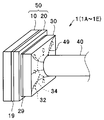
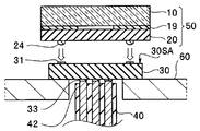
- the imaging module 1 includes a cover glass 10, an imaging element chip 20, a wiring board 30, and a cable 40.
- the imaging element chip 20 to which the cover glass 10 is bonded is referred to as an imaging chip 50.
- a transparent cover glass 10 is bonded to the front surface 20SA of the imaging element chip 20 via an adhesive layer 19.
- the adhesive layer 19 is not disposed on the CCD 21.
- the imaging chip 50 is manufactured by cutting and separating one bonded wafer 50W (see FIG. 5) by wafer level chip size package (WL-CSP) technology. Therefore, the outer size of the cover glass 10 is the same as the outer size of the imaging element chip 20.
- the external electrode 24 of the back surface 20SB of the imaging chip 50 is bonded to the chip electrode 31 of the first main surface 30SA of the wiring board 30.
- a space between the imaging chip 50 and the wiring board 30 is sealed by a sealing resin 29.
- the outer size of the wiring board 30 is smaller than the outer size of the imaging chip 50.
- the conducting wire 42 of the cable 40 is joined to the cable electrode 33 of the second main surface 30SB of the wiring board 30.
- the cable electrode 33 is connected to the chip electrode 31 of the first main surface 30SA via the through wiring 32 and the surface wiring 34 of the second main surface 30SB.
- the junction between the wiring board 30 and the cable 40 is covered with a sealing resin 49.
- the imaging module 1 is characterized in the relative arrangement, that is, the positional relationship between the tip electrode 31 of the wiring board 30 and the cable electrode 33.
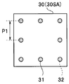
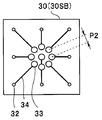
- the outer peripheral portion of the first main surface 30SA of the wiring board 30 (near the outer side of the wiring board 30 in plan view and its periphery, ie, the surface on the side closer to the peripheral edge) , Eight chip electrodes 31 are disposed, and the central portion of the second main surface 30SB (near the center of wiring board 30 and its periphery in plan view, that is, on the inner surface) , Nine cable electrodes 33 are disposed.
- the arrangement interval P1 of the plurality of tip electrodes 31 arranged in the outer peripheral portion is wider than the arrangement interval P2 of the plurality of cable electrodes 33 arranged in the central portion.
- the chip electrode 31 and the cable electrode 33 are connected through the through wiring 32.
- the cable electrode 33 is disposed in a region not facing the disposition region of the tip electrode 31. In other words, in the transmission plan view, the cable electrode 33 and the tip electrode 31 are not displayed in an overlapping manner.
- the chip electrode 31 is disposed immediately above the through wiring 32
- the cable electrode 33 is disposed at the central portion of the wiring board 30 separated from the through wiring 32 via the surface wiring 34.
- the imaging module 1 is manufactured by bonding the cable 40 to the second main surface 30SB of the wiring board 30, and then forming the CSP type imaging chip 50 as the first main surface 30SA of the wiring board 30.
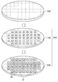
- a plurality of CCDs 21 and a plurality of signal processing circuits are formed on the front surface of the silicon wafer 20W using known semiconductor technology.
- a micro lens and a color filter may be disposed on the CCD 21.
- a COMS image sensor or the like may be used as the solid-state imaging device.
- a plurality of CCD electrode pads 22 connected to the CCD 21 via respective wirings (not shown) extended from the signal processing circuit are arranged on the outer peripheral portion of each CCD 21.
- the transparent glass wafer 10W is bonded to the front surface of the silicon wafer 20W, that is, the surface on which the CCD 21 is formed via the adhesive layer 19W, whereby a bonded wafer 50W is produced.
- An opening is formed in the adhesive layer 19 W above at least the effective imaging element forming region of the CCD 21. Therefore, a cavity is formed between the CCD 21 formation region of the silicon wafer 20W and the glass wafer 10W. Depending on the specifications of the imaging module, it may not be necessary to form a cavity.
- a photoresist is used on the back surface of the bonded wafer 50W (silicon wafer 20W), and an etching mask having an opening at a position facing the CCD electrode pad 22 is disposed. Then, dry etching such as ICP-RIE from the back surface side is used to form a through hole which penetrates the silicon wafer 20 W and reaches the back surface of the CCD electrode pad 22. For the formation of the through holes, wet etching using an alkaline solution such as KOH or TMAH may be used, for example.
- an alkaline solution such as KOH or TMAH
- a through wire 23 made of a conductive material covering the inside of the through hole is manufactured, and the inside of the through hole is filled with a conductive material or the like. Furthermore, the external electrode 24 is manufactured on the back surface side of the through wiring 23.
- the external electrode 24 is a convex bump made of gold, solder or the like.
- the external electrode 24 is produced, for example, by forming a plating bump or a stud bump on the electrode pattern.
- the bonding wafer 50W is cut / divided along the dashed line shown in FIG. 5 by a blade dicing method, whereby a plurality of imaging chips 50 are manufactured collectively.
- the wiring board 30 is manufactured using a double-sided wiring board.
- the wiring board 30 has a plurality of chip electrodes 31 on the outer peripheral portion of the first major surface 30SA. The position of each tip electrode 31 is set to coincide with the position of the corresponding external electrode 24 of the imaging chip 50. A through wire 32 reaching the second main surface 30SB is formed immediately below the chip electrode 31.
- the wiring board 30 has a plurality of cable electrodes 33 at the center of the second main surface 30SB. The cable electrode 33 connected to the through wire 32 through the surface wire 34 is set to coincide with the position of the corresponding wire 42 of the cable 40.
- the outer size of the wiring board 30 is smaller than the outer size of the imaging chip 50 in order to reduce the diameter of the imaging module 1.
- the cable electrode 33 of the wiring board 30 and the conducting wire 42 of the cable 40 are joined.
- a joint to which thermal energy is locally applied is heated to a temperature higher than the melting point of the solder.
- heater heating, laser heating, lamp heating, or the like may be used, and heating may be performed while applying pressure as necessary.
- bonding may be performed by applying different energy, for example, applying ultrasonic energy or the like.
- a sealing resin 49 is disposed around the periphery.
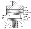
- the wiring board 30 holds the first main surface 30SA upward on the stage 60 having a hole through which the cable 40 can be inserted.
- the imaging chip 50 is aligned such that the external electrode 24 abuts on the chip electrode 31 of the first main surface 30SA of the wiring board 30. Then, thermal energy is locally applied to the contact portion between the tip electrode 31 and the external electrode 24 through the stage 60, whereby the bonding process is performed.
- a sealing resin 29 is disposed at the joint portion.
- the sealing resin 29 seals the periphery of the bonding portion to improve the reliability of connection, and at the same time, bonds the imaging chip 50 and the wiring board 30.
- epoxy resin, silicone resin, acrylic resin, phenol resin or the like is used as the sealing resin 29, epoxy resin, silicone resin, acrylic resin, phenol resin or the like.
- An anisotropic conductive paste (ACP), an anisotropic conductive film (ACF), an insulating paste (NCP) or the like may be used as the sealing resin 29.
- the sealing resin 29 may not be used.
- the chip electrode 31 and the cable electrode 33 are not provided at the same position on the front and back of the wiring board 30. For this reason, when the joint between the tip electrode 31 and the external electrode 24 is locally heated, unnecessary thermal energy and thermal stress are applied to the joint between the cable electrode 33 and the cable 40 already joined. I have not.
- the imaging module 1 has high connection reliability while realizing reduction in diameter.
- the imaging chip 50 may be joined to the wiring board 30 by holding the imaging chip 50 by the collet 61 and applying thermal energy to the joint via the collet 61. .
- the cable 40 and the wiring board 30 may be bonded after the imaging chip 50 and the wiring board 30 are bonded.
- imaging modules 1A to 1F of modifications of the embodiment will be described.
- the imaging modules 1A to 1F of the modified example are similar to the imaging module 1 of the embodiment, so the same components are denoted by the same reference numerals and descriptions thereof will be omitted.
- the cable electrode 33 is disposed in a region not facing the disposition region of the chip electrode 31, so all of them are imaged It has the same effect as module 1.
- the chip electrode 31 is disposed at the center of the first main surface 30SA of the wiring board 30A, and is separated from the chip electrode 31 via the surface wiring 35. It is connected to the through wire 32 at the position.
- the cable electrode 33 is arrange
- the chip electrode 31 is disposed at the central portion and the peripheral portion of the first main surface 30SA of the wiring board 30B.
- a part of the chip electrodes 31 is connected to the through wiring 32 through the surface wiring 35, and a part of the chip electrodes 31 is connected to the through wiring 32 immediately below.
- the cable electrode 33 is arrange
- a portion of the cable electrodes 33 is disposed immediately above the through wiring 32, and a portion of the cable electrodes 33 is disposed at a distance from the through wiring 32 via the surface wiring 34. Further, a part of the through wiring 32 connects the cable electrode 33 and the chip electrode 31 through the surface wirings 34 and 35.
- the plurality of chip electrodes 31 are disposed in a region eccentric from the center of the first main surface 30SA of the wiring board 30C. Then, as in the imaging module 1B, the surface wiring 35 is disposed on the first main surface 30SA, the surface wiring 34 is disposed on the second main surface 30SB, and the cable electrode 33 is a chip It is arrange
- the chip electrode 31C of the first main surface 30SA is a dummy electrode for securing the balance of bonding.
- the electronic component 36 is surface-mounted on the surface wiring 34 of the second main surface 30SB of the wiring board 30C.
- the mounted electronic component is, for example, a chip component such as a chip capacitor.
- a multilayer wiring board or a component built-in board may be used as the wiring board.
- ⁇ Modification 4> As shown in FIG. 11, in the imaging module 1D of the fourth modification, the ends of the plurality of conducting wires 42 of the cable 40 are rearranged according to the arrangement of the plurality of cable electrodes 33 of the wiring board 30. It is integrated.
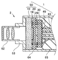
- the imaging unit 2 includes the imaging module 1 described above, and an optical member that forms an object image on the light receiving surface of the imaging element chip. That is, in the imaging unit 2, the lens unit 62 (optical lens and lens barrel for holding the same) and the lens unit holder 63 for holding the same are housed inside the shield frame 64 together with the imaging module 1. Is sealed by the filling resin 65.
- the imaging unit 2 including the imaging module 1 has high connection reliability and a small diameter, and thus is suitable for being disposed at the tip of the electronic endoscope.
- An imaging unit having imaging modules 1A to 1E instead of the imaging module 1 also has the same effect as the imaging unit 2.
Landscapes
- Physics & Mathematics (AREA)
- Engineering & Computer Science (AREA)
- Power Engineering (AREA)
- General Physics & Mathematics (AREA)
- Computer Hardware Design (AREA)
- Condensed Matter Physics & Semiconductors (AREA)
- Electromagnetism (AREA)
- Microelectronics & Electronic Packaging (AREA)
- Signal Processing (AREA)
- Multimedia (AREA)
- Optics & Photonics (AREA)
- Solid State Image Pick-Up Elements (AREA)
- Transforming Light Signals Into Electric Signals (AREA)
- Studio Devices (AREA)
- Lens Barrels (AREA)
- Endoscopes (AREA)
Abstract
撮像モジュール1は、第1の主面30SAにチップ電極31が配設されており、第2の主面30SBに貫通配線32を介してチップ電極31と接続されているケーブル電極33が配設されている配線板30と、チップ電極31と接合された外部電極24を有する撮像素子チップ20と、ケーブル電極33と接合された導線42を有するケーブル40と、を具備し、ケーブル電極33がチップ電極31の配設領域と対向していない領域に配設されている。
Description
本発明は、撮像チップと、前記撮像チップと接合された配線板と、前記配線板を介して前記撮像チップと接合されたケーブルと、を具備する撮像モジュールおよび前記撮像モジュールを具備する撮像ユニットに関する。
図1に示す撮像モジュール101が日本国特開2010-263020号公報に開示されている。撮像モジュール101は、カバーガラス110と、撮像素子チップ120と、配線板130と、ケーブル140と、を有する。カバーガラス110と撮像素子チップ120とは接着層119により接合されており、撮像素子チップ120と配線板130とは補強部材129により接合されている。また配線板130とケーブル140との接合部は補強部材149で覆われている。
撮像素子チップ120の外部電極122は、配線板130のチップ電極132と接合されている。配線板130にはチップ電極132の裏面に到達する貫通孔131がある。ケーブル140の導線142は、貫通孔131に挿入された状態で接合されることで、チップ電極132と電気的に接続されている。
撮像モジュール101では、配線板130の貫通孔131に挿入された導線142を接合するときに、すでに接合されている外部電極122とチップ電極132との接合部にも、熱エネルギーまたは機械的負荷が印加される。
このため、撮像モジュール101は、小型化・細径化を図ろうとすると、接合部に不具合が生じ、接続信頼性が低下するおそれがあった。
本発明は、接続信頼性の高い細径の撮像モジュールおよび接続信頼性の高い細径の撮像ユニットを提供することを目的とする。
本発明の実施形態の撮像モジュールは、第1の主面にチップ電極が配設されており、第2の主面に貫通配線を介して前記チップ電極と接続されているケーブル電極が配設されている配線板と、前記チップ電極と接合された外部電極を有する撮像素子チップと、前記ケーブル電極と接合された導線を有するケーブルと、を具備し、前記ケーブル電極が前記チップ電極の配設領域と対向していない領域に配設されている。
また、別の実施形態の撮像ユニットは、第1の主面にチップ電極が配設されており、第2の主面に貫通配線を介して前記チップ電極と接続されているケーブル電極が配設されている配線板と、前記チップ電極と接合された外部電極を有する撮像素子チップと、前記ケーブル電極と接合された導線を有するケーブルと、を具備し、前記ケーブル電極が前記チップ電極の配設領域と対向していない領域に配設されている撮像モジュールと、前記撮像素子チップの受光面に被写体像を結像する光学部材とを具備する。
<第1実施形態>
図2~図4Bを用いて、本発明の実施形態の撮像モジュール1の構造について説明する。なお図は、いずれも説明のための模式図であり、縦横の寸法比等は実際とは異なっている。また一部の構成要素の図示を省略することがある。
図2~図4Bを用いて、本発明の実施形態の撮像モジュール1の構造について説明する。なお図は、いずれも説明のための模式図であり、縦横の寸法比等は実際とは異なっている。また一部の構成要素の図示を省略することがある。
図2および図3に示すように、撮像モジュール1は、カバーガラス10と、撮像素子チップ20と、配線板30と、ケーブル40と、を具備する。なお、カバーガラス10が接合された撮像素子チップ20を、撮像チップ50という。
シリコン等の半導体からなる撮像素子チップ20のおもて面20SAの略中央部には固体撮像素子であるCCD21が形成されている。CCD21と接続された信号処理回路(不図示)からの配線(不図示)は、CCD電極パッド22と貫通配線23とを介して裏面20SBの外部電極24に接続されている。
撮像素子チップ20のおもて面20SAには、透明なカバーガラス10が接着層19を介して接合されている。なお、接着層19はCCD21の上には配設されていない。後述するように、撮像チップ50は、ウエハレベルチップサイズパッケージ(WL-CSP)技術により、1枚の接合ウエハ50W(図5参照)を切断し個片化することにより作製される。このため、カバーガラス10の外寸は、撮像素子チップ20の外寸と同じである。
撮像チップ50の裏面20SBの外部電極24は、配線板30の第1の主面30SAのチップ電極31と接合されている。撮像チップ50と配線板30との間は、封止樹脂29で封止されている。配線板30の外寸は、撮像チップ50の外寸よりも小さい。
ケーブル40の導線42は、配線板30の第2の主面30SBのケーブル電極33と接合されている。ケーブル電極33は、貫通配線32および第2の主面30SBの表面配線34を介して、第1の主面30SAのチップ電極31と接続されている。配線板30とケーブル40の接合部は封止樹脂49で覆われている。なお、図示にあたっての便宜上、導線42は全て直線形状で表示しているが、部分的に曲がっていたり互いに撚られていたりしてもよい。
撮像モジュール1は、配線板30のチップ電極31とケーブル電極33との相対的な配置すなわち位置関係に特徴がある。
すなわち、図4Aおよび図4Bに示すように、配線板30の第1の主面30SAの外周部(平面視したときの配線板30の外辺近傍とその周辺、すなわち周縁寄りの側の面上)には、8個のチップ電極31が配設されており、第2の主面30SBの中央部(平面視したときの配線板30の中心近傍とその周辺、すなわち内側の面上)には、9個のケーブル電極33が配設されている。外周部に配置されている複数のチップ電極31の配置間隔P1は、中央部に配置されている複数のケーブル電極33の配置間隔P2よりも広い。
チップ電極31とケーブル電極33とは、貫通配線32を介して接続されている。しかし、撮像モジュール1では、ケーブル電極33は、チップ電極31の配設領域と対向していない領域に配設されている。言い換えれば、透過平面図において、ケーブル電極33とチップ電極31とは重複して表示されることがない。
すなわち、チップ電極31は貫通配線32の直上に配設されているが、ケーブル電極33は、表面配線34を介して貫通配線32から離れた配線板30の中央部に配設されている。
次に、撮像モジュール1の製造方法について説明する。
撮像モジュール1は、配線板30の第2の主面30SBにケーブル40を接合した後に、CSPタイプの撮像チップ50を配線板30の第1の主面30SAすることで製造される。
<撮像チップの作製>
図5に示すように、シリコンウエハ20Wのおもて面に公知の半導体技術を用いて複数のCCD21および複数の信号処理回路(不図示)が形成される。なお、CCD21上に、マイクロレンズおよびカラーフィルタを配設してもよい。また、固体撮像素子としてはCOMSイメージセンサ等でもよい。
図5に示すように、シリコンウエハ20Wのおもて面に公知の半導体技術を用いて複数のCCD21および複数の信号処理回路(不図示)が形成される。なお、CCD21上に、マイクロレンズおよびカラーフィルタを配設してもよい。また、固体撮像素子としてはCOMSイメージセンサ等でもよい。
さらに、信号処理回路から延設された、それぞれの配線(不図示)を介してCCD21と接続されている複数のCCD電極パッド22が、それぞれのCCD21の外周部に配設される。
<接合ウエハの作製>
シリコンウエハ20Wのおもて面、すなわち、CCD21形成面に、接着層19Wを介して透明なガラスウエハ10Wが接合されることで接合ウエハ50Wが作製される。CCD21の少なくとも有効撮像素子形成領域の上の接着層19Wには開口が形成されている。このため、シリコンウエハ20WのCCD21形成領域と、ガラスウエハ10Wとの間には、空洞部が形成される。なお、撮像モジュールの仕様によっては、空洞部を形成する必要がない場合もある。
シリコンウエハ20Wのおもて面、すなわち、CCD21形成面に、接着層19Wを介して透明なガラスウエハ10Wが接合されることで接合ウエハ50Wが作製される。CCD21の少なくとも有効撮像素子形成領域の上の接着層19Wには開口が形成されている。このため、シリコンウエハ20WのCCD21形成領域と、ガラスウエハ10Wとの間には、空洞部が形成される。なお、撮像モジュールの仕様によっては、空洞部を形成する必要がない場合もある。
<貫通配線の作製>
接合ウエハ50W(シリコンウエハ20W)の裏面にフォトレジストを用いて、CCD電極パッド22と対向する位置に開口のあるエッチングマスクが配設される。そして、裏面側からのICP-RIE等のドライエッチングを用いて、シリコンウエハ20Wを貫通しCCD電極パッド22の裏面に到達する貫通孔が形成される。貫通孔の形成には、例えば、KOHまたはTMAH等のアルカリ溶液を用いたウエットエッチングを用いてもよい。
接合ウエハ50W(シリコンウエハ20W)の裏面にフォトレジストを用いて、CCD電極パッド22と対向する位置に開口のあるエッチングマスクが配設される。そして、裏面側からのICP-RIE等のドライエッチングを用いて、シリコンウエハ20Wを貫通しCCD電極パッド22の裏面に到達する貫通孔が形成される。貫通孔の形成には、例えば、KOHまたはTMAH等のアルカリ溶液を用いたウエットエッチングを用いてもよい。
次に、貫通孔の内部を覆う導電性材料からなる貫通配線23が作製され、貫通孔の内部は導電性材料等で充填される。さらに、貫通配線23の裏面側には、外部電極24が作製される。外部電極24は、金、または、はんだ等からなる凸形状バンプである。外部電極24は、例えば、電極パターンの上に、めっきバンプまたはスタッドバンプ等を形成することにより作製される。
<個片化>
接合ウエハ50Wが、図5に示す破線に沿ってブレードダイシング法により切断/個片化されることにより、一括して複数の撮像チップ50が作製される。
接合ウエハ50Wが、図5に示す破線に沿ってブレードダイシング法により切断/個片化されることにより、一括して複数の撮像チップ50が作製される。
<配線板の作製>
別途、例えば、両面配線基板を用いて、配線板30が作製される。配線板30は、第1の主面30SAの外周部に複数のチップ電極31を有する。それぞれのチップ電極31の位置は、撮像チップ50の対応する外部電極24の位置と、一致するように設定されている。チップ電極31の直下には第2の主面30SBに到達する貫通配線32が形成されている。一方、配線板30は、第2の主面30SBの中央部に複数のケーブル電極33を有する。表面配線34を介して貫通配線32と接続されたケーブル電極33は、ケーブル40の対応する導線42の位置と、一致するように設定されている。なお、すでに説明したように、撮像モジュール1の細径化のために、配線板30の外寸は、撮像チップ50の外寸よりも小さい。
別途、例えば、両面配線基板を用いて、配線板30が作製される。配線板30は、第1の主面30SAの外周部に複数のチップ電極31を有する。それぞれのチップ電極31の位置は、撮像チップ50の対応する外部電極24の位置と、一致するように設定されている。チップ電極31の直下には第2の主面30SBに到達する貫通配線32が形成されている。一方、配線板30は、第2の主面30SBの中央部に複数のケーブル電極33を有する。表面配線34を介して貫通配線32と接続されたケーブル電極33は、ケーブル40の対応する導線42の位置と、一致するように設定されている。なお、すでに説明したように、撮像モジュール1の細径化のために、配線板30の外寸は、撮像チップ50の外寸よりも小さい。
<配線板とケーブルとの接合>
配線板30のケーブル電極33とケーブル40の導線42とが、接合される。接合には、接合部に外部からエネルギーを印加する必要がある。例えば、はんだ接合の場合には、熱エネルギーが局所的に印加された接合箇所が、はんだ融点以上に加熱される。局所加熱には、ヒーター加熱、レーザー加熱またはランプ加熱等を用い、必要に応じて圧力を加えながら加熱してもよい。なお、熱エネルギー印加に換えて、異なるエネルギーの印加、例えば超音波エネルギー等の印加により接合してもよい。
配線板30のケーブル電極33とケーブル40の導線42とが、接合される。接合には、接合部に外部からエネルギーを印加する必要がある。例えば、はんだ接合の場合には、熱エネルギーが局所的に印加された接合箇所が、はんだ融点以上に加熱される。局所加熱には、ヒーター加熱、レーザー加熱またはランプ加熱等を用い、必要に応じて圧力を加えながら加熱してもよい。なお、熱エネルギー印加に換えて、異なるエネルギーの印加、例えば超音波エネルギー等の印加により接合してもよい。
接合後に、接合部の機械的強度を向上するために、周囲に封止樹脂49が配設される。
<撮像チップと配線板との接合>
ケーブル40が接合された配線板30のチップ電極31に、撮像チップ50の外部電極24が接合される。ケーブル電極33とケーブル40との接合と同様に、この接合にも接合部にエネルギーの印加が必要である。
ケーブル40が接合された配線板30のチップ電極31に、撮像チップ50の外部電極24が接合される。ケーブル電極33とケーブル40との接合と同様に、この接合にも接合部にエネルギーの印加が必要である。
図6に示すように、ケーブル40が挿通可能な穴のあるステージ60に配線板30が第1の主面30SAが上向きに保持される。配線板30の第1の主面30SAのチップ電極31に、外部電極24が当接するように撮像チップ50が位置合わせされる。そして、ステージ60を介して、チップ電極31と外部電極24との当接部に局部的に熱エネルギーが印加されることで、接合処理が行われる。
なお、図6には図示しないが、図3等に示すように接合部には封止樹脂29が配設される。封止樹脂29は、接合部の周囲を封止し接続の信頼性を高めると同時に、撮像チップ50と配線板30とを接合している。封止樹脂29としては、エポキシ系樹脂、シリコーン系樹脂、アクリル系樹脂、またはフェーノール系樹脂等を用いる。
なお、封止樹脂29として、異方性導電ペースト(ACP)、異方性導電膜(ACF)、絶縁性ペースト(NCP)等を用いてもよい。なお、封止樹脂29を用いなくともよい。
すでに説明したように、撮像モジュール1では、チップ電極31とケーブル電極33とは配線板30の表裏において一致する位置には設けられていない。このため、チップ電極31と外部電極24との接合部を局所加熱するときに、すでに接合されているケーブル電極33とケーブル40との接合部には、不要な熱エネルギーおよび熱応力が印加されることがない。
このため、撮像モジュール1は、細径化を実現しながら、高い接続信頼性を有する。
なお、図7に示すように、撮像チップ50をコレット61で保持するとともに、コレット61を介して接合部に熱エネルギーを印加することで、撮像チップ50と配線板30とを接合してもよい。
また、撮像チップ50と配線板30とを接合した後に、ケーブル40と配線板30とを接合してもよい。
<実施形態の変形例>
次に、実施形態の変形例の撮像モジュール1A~1Fについて説明する。変形例の撮像モジュール1A~1Fは、実施形態の撮像モジュール1と類似しているので、同じ構成要素には同じ符号を付し説明は省略する。
次に、実施形態の変形例の撮像モジュール1A~1Fについて説明する。変形例の撮像モジュール1A~1Fは、実施形態の撮像モジュール1と類似しているので、同じ構成要素には同じ符号を付し説明は省略する。
以下の説明のように、撮像モジュール1A~1Fは、撮像モジュール1と同様に、ケーブル電極33が、チップ電極31の配設領域と対向していない領域に配設されているため、いずれも撮像モジュール1と同じ効果を有する。
<変形例1>
図8Aに示すように、変形例1の撮像モジュール1Aでは、配線板30Aの第1の主面30SAの中央部にチップ電極31が配設され、表面配線35を介してチップ電極31と離れた位置にある貫通配線32と接続されている。そして、図8Bに示すように、配線板30Aの第2の主面30SBの周辺部に形成された貫通配線32の直上にケーブル電極33が配設されている。
図8Aに示すように、変形例1の撮像モジュール1Aでは、配線板30Aの第1の主面30SAの中央部にチップ電極31が配設され、表面配線35を介してチップ電極31と離れた位置にある貫通配線32と接続されている。そして、図8Bに示すように、配線板30Aの第2の主面30SBの周辺部に形成された貫通配線32の直上にケーブル電極33が配設されている。
<変形例2>
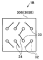
図9Aに示すように、変形例2の撮像モジュール1Bでは、配線板30Bの第1の主面30SAの中央部および周辺部にチップ電極31が配設されている。一部のチップ電極31は表面配線35を介して貫通配線32と接続されており、一部のチップ電極31は直下の貫通配線32と接続されている。そして、図9Bに示すように、配線板30Bの第2の主面30SBの中央部および周辺部にケーブル電極33が配設されている。一部のケーブル電極33は、貫通配線32の直上に配設されており、一部のケーブル電極33は、表面配線34を介して貫通配線32と離れた位置に配設されている。また一部の貫通配線32は表面配線34、35を介してケーブル電極33とチップ電極31とを接続している。
図9Aに示すように、変形例2の撮像モジュール1Bでは、配線板30Bの第1の主面30SAの中央部および周辺部にチップ電極31が配設されている。一部のチップ電極31は表面配線35を介して貫通配線32と接続されており、一部のチップ電極31は直下の貫通配線32と接続されている。そして、図9Bに示すように、配線板30Bの第2の主面30SBの中央部および周辺部にケーブル電極33が配設されている。一部のケーブル電極33は、貫通配線32の直上に配設されており、一部のケーブル電極33は、表面配線34を介して貫通配線32と離れた位置に配設されている。また一部の貫通配線32は表面配線34、35を介してケーブル電極33とチップ電極31とを接続している。
<変形例3>
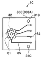
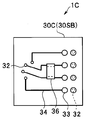
図10Aに示すように、変形例3の撮像モジュール1Cでは、配線板30Cの第1の主面30SAの中央から偏芯した領域に複数のチップ電極31が配設されている。そして、撮像モジュール1Bと同様に、第1の主面30SAに表面配線35が配設されており、第2の主面30SBにも表面配線34が配設されており、ケーブル電極33は、チップ電極31の配設領域と対向していない領域に配設されている。なお、第1の主面30SAのチップ電極31Cは、接合のバランスを確保するためのダミー電極である。
図10Aに示すように、変形例3の撮像モジュール1Cでは、配線板30Cの第1の主面30SAの中央から偏芯した領域に複数のチップ電極31が配設されている。そして、撮像モジュール1Bと同様に、第1の主面30SAに表面配線35が配設されており、第2の主面30SBにも表面配線34が配設されており、ケーブル電極33は、チップ電極31の配設領域と対向していない領域に配設されている。なお、第1の主面30SAのチップ電極31Cは、接合のバランスを確保するためのダミー電極である。
さらに、図10Bに示すように、撮像モジュール1Cでは、配線板30Cの第2の主面30SBの表面配線34に電子部品36が表面実装されている。実装されている電子部品は例えばチップコンデンサ等のチップ部品である。なお、配線板として、多層配線板または部品内蔵基板を用いてもよい。
<変形例4>
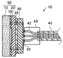
図11に示すように、変形例4の撮像モジュール1Dでは、ケーブル40の複数の導線42の端部が、配線板30の複数のケーブル電極33の配列にあわせて再配列され、ブロック部材43により一体化されている。
図11に示すように、変形例4の撮像モジュール1Dでは、ケーブル40の複数の導線42の端部が、配線板30の複数のケーブル電極33の配列にあわせて再配列され、ブロック部材43により一体化されている。
<変形例5>
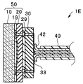
図12に示すように、変形例5の撮像モジュール1Eでは、ケーブル40の複数の導線42の端部が、配線板30の複数のケーブル電極33の配列にあわせて折り曲げられている。そして、ケーブル電極33と導線42とは、はんだ付けされている。
図12に示すように、変形例5の撮像モジュール1Eでは、ケーブル40の複数の導線42の端部が、配線板30の複数のケーブル電極33の配列にあわせて折り曲げられている。そして、ケーブル電極33と導線42とは、はんだ付けされている。
<第2実施形態>
図13に示すように、本発明の第2実施形態の撮像ユニット2は、すでに説明した撮像モジュール1と、撮像素子チップの受光面に被写体像を結像する光学部材と、を具備する。すなわち、撮像ユニット2は、レンズユニット62(光学レンズおよびそれを保持するレンズバレル)とそれを保持するレンズユニットホルダ63とが、撮像モジュール1とともにシールド枠64の内側に収容されており、ケーブル40は充填樹脂65により封止されている。撮像モジュール1を具備する撮像ユニット2は、接続信頼性が高く、細径であるために、電子内視鏡の先端部に配設するのに適している。なお、撮像モジュール1に替えて撮像モジュール1A~1Eを具備している撮像ユニットも、撮像ユニット2と同様の効果を有する。
図13に示すように、本発明の第2実施形態の撮像ユニット2は、すでに説明した撮像モジュール1と、撮像素子チップの受光面に被写体像を結像する光学部材と、を具備する。すなわち、撮像ユニット2は、レンズユニット62(光学レンズおよびそれを保持するレンズバレル)とそれを保持するレンズユニットホルダ63とが、撮像モジュール1とともにシールド枠64の内側に収容されており、ケーブル40は充填樹脂65により封止されている。撮像モジュール1を具備する撮像ユニット2は、接続信頼性が高く、細径であるために、電子内視鏡の先端部に配設するのに適している。なお、撮像モジュール1に替えて撮像モジュール1A~1Eを具備している撮像ユニットも、撮像ユニット2と同様の効果を有する。
本発明は上述した実施形態または変形例等に限定されるものではなく、本発明の要旨を変えない範囲において、種々の変更、改変、組み合わせ等ができる。
本出願は、2011年12月5日に日本国に出願された特願2011-266073号を優先権主張の基礎として出願するものであり、上記の開示内容は、本願明細書、請求の範囲、図面に引用されたものとする。
Claims (8)
- 第1の主面にチップ電極が配設されており、第2の主面に貫通配線を介して前記チップ電極と接続されているケーブル電極が配設されている配線板と、
前記チップ電極と接合された外部電極を有する撮像素子チップと、
前記ケーブル電極と接合された導線を有するケーブルと、を具備する撮像モジュールであって、
前記ケーブル電極が前記チップ電極の配設領域と対向していない領域に配設されていることを特徴とする。 - 前記チップ電極が、前記第1の主面の外周部に配設されており、
前記ケーブル電極が、前記第2の主面の中央部に配設されていることを特徴とする請求項1に記載の撮像モジュール。 - 前記チップ電極が、前記第1の主面の中央部に配設されており、
前記ケーブル電極が、前記第2の主面の外周部に配設されていることを特徴とする請求項1に記載の撮像モジュール。 - 前記配線板の、前記第2の主面の前記チップ電極の配設領域と対向していない領域に電子部品が表面実装されていることを特徴とする請求項1に記載の撮像モジュール。
- 第1の主面にチップ電極が配設されており、第2の主面に貫通配線を介して前記チップ電極と接続されているケーブル電極が配設されている配線板と、前記チップ電極と接合された外部電極を有する撮像素子チップと、前記ケーブル電極と接合された導線を有するケーブルと、を具備し、前記ケーブル電極が前記チップ電極の配設領域と対向していない領域に配設されている撮像モジュールと、
前記撮像素子チップの受光面に被写体像を結像する光学部材と、を具備することを特徴とする撮像ユニット。 - 前記チップ電極が、前記第1の主面の外周部に配設されており、
前記ケーブル電極が、前記第2の主面の中央部に配設されていることを特徴とする請求項5に記載の撮像ユニット。 - 前記チップ電極が、前記第1の主面の中央部に配設されており、
前記ケーブル電極が、前記第2の主面の外周部に配設されていることを特徴とする請求項5に記載の撮像ユニット。 - 前記配線板の、前記第2の主面の前記チップ電極の配設領域と対向していない領域に電子部品が表面実装されていることを特徴とする請求項5に記載の撮像ユニット。
Priority Applications (2)
| Application Number | Priority Date | Filing Date | Title |
|---|---|---|---|
| EP12854656.1A EP2790218A4 (en) | 2011-12-05 | 2012-09-07 | IMAGING MODULE AND IMAGING UNIT |
| US14/291,178 US9455358B2 (en) | 2011-12-05 | 2014-05-30 | Image pickup module and image pickup unit |
Applications Claiming Priority (2)
| Application Number | Priority Date | Filing Date | Title |
|---|---|---|---|
| JP2011266073A JP5757852B2 (ja) | 2011-12-05 | 2011-12-05 | 撮像モジュールおよび撮像ユニット |
| JP2011-266073 | 2011-12-05 |
Related Child Applications (1)
| Application Number | Title | Priority Date | Filing Date |
|---|---|---|---|
| US14/291,178 Continuation US9455358B2 (en) | 2011-12-05 | 2014-05-30 | Image pickup module and image pickup unit |
Publications (1)
| Publication Number | Publication Date |
|---|---|
| WO2013084553A1 true WO2013084553A1 (ja) | 2013-06-13 |
Family
ID=48573937
Family Applications (1)
| Application Number | Title | Priority Date | Filing Date |
|---|---|---|---|
| PCT/JP2012/072882 WO2013084553A1 (ja) | 2011-12-05 | 2012-09-07 | 撮像モジュールおよび撮像ユニット |
Country Status (4)
| Country | Link |
|---|---|
| US (1) | US9455358B2 (ja) |
| EP (1) | EP2790218A4 (ja) |
| JP (1) | JP5757852B2 (ja) |
| WO (1) | WO2013084553A1 (ja) |
Families Citing this family (15)
| Publication number | Priority date | Publication date | Assignee | Title |
|---|---|---|---|---|
| JP6344935B2 (ja) * | 2014-03-13 | 2018-06-20 | Hoya株式会社 | 半導体装置及び内視鏡 |
| JPWO2015141802A1 (ja) * | 2014-03-20 | 2017-04-13 | オリンパス株式会社 | 実装構造体の製造方法、実装用治具、実装構造体の製造装置、撮像装置および内視鏡装置 |
| JP6515431B2 (ja) * | 2015-03-31 | 2019-05-22 | 国立大学法人東北大学 | 挿入器具および挿入器具の製造方法 |
| WO2016166890A1 (ja) | 2015-04-17 | 2016-10-20 | オリンパス株式会社 | 撮像装置 |
| CN107613838A (zh) * | 2015-05-29 | 2018-01-19 | 奥林巴斯株式会社 | 摄像装置、内窥镜系统以及摄像装置的制造方法 |
| US10122953B2 (en) | 2015-11-30 | 2018-11-06 | Fujikura Ltd. | Imaging module |
| JP2019047300A (ja) | 2017-08-31 | 2019-03-22 | 株式会社フジクラ | 撮像モジュール及びハーネスユニット |
| TWI646939B (zh) * | 2017-11-10 | 2019-01-11 | 沅聖科技股份有限公司 | 微內視鏡裝置 |
| WO2019138462A1 (ja) * | 2018-01-10 | 2019-07-18 | オリンパス株式会社 | 撮像装置、内視鏡、および、撮像装置の製造方法 |
| WO2019176601A1 (ja) * | 2018-03-14 | 2019-09-19 | オリンパス株式会社 | 撮像ユニットおよび斜視型内視鏡 |
| CN108511475B (zh) * | 2018-05-17 | 2023-10-10 | 黄琴 | 一种超小型pad的辅助焊接元件的制造方法和辅助焊接方法 |
| JP6792661B2 (ja) * | 2019-03-27 | 2020-11-25 | Hoya株式会社 | 撮像モジュール及び内視鏡 |
| JP2020194854A (ja) * | 2019-05-27 | 2020-12-03 | 株式会社 Rosnes | 固体撮像装置へ配線する製造方法 |
| CN116635769A (zh) * | 2021-01-18 | 2023-08-22 | 三星电子株式会社 | 包括微型相机的可穿戴的电子装置 |
| JPWO2024053097A1 (ja) * | 2022-09-09 | 2024-03-14 |
Citations (5)
| Publication number | Priority date | Publication date | Assignee | Title |
|---|---|---|---|---|
| JP2000092477A (ja) * | 1998-09-07 | 2000-03-31 | Olympus Optical Co Ltd | 撮像装置 |
| JP2004031498A (ja) * | 2002-06-24 | 2004-01-29 | Fuji Photo Film Co Ltd | 固体撮像装置の製造方法 |
| JP2006051258A (ja) * | 2004-08-16 | 2006-02-23 | Pentax Corp | 電子内視鏡の先端部 |
| JP2006324304A (ja) * | 2005-05-17 | 2006-11-30 | Yuutekku System:Kk | 半導体パッケージ及びイメージセンサー型モジュール |
| JP2010263020A (ja) | 2009-04-30 | 2010-11-18 | Panasonic Corp | 光学デバイスモジュール |
Family Cites Families (4)
| Publication number | Priority date | Publication date | Assignee | Title |
|---|---|---|---|---|
| TW332348B (en) * | 1992-06-23 | 1998-05-21 | Sony Co Ltd | Manufacturing method for solid state motion picture device provides a highly accurate and low cost solid state motion picture device by use of empty package made of resin. |
| JP2001118967A (ja) * | 1999-10-19 | 2001-04-27 | Sanyo Electric Co Ltd | 固体撮像素子のパッケージ構造 |
| DE102004056946A1 (de) * | 2004-11-23 | 2006-05-24 | Karl Storz Gmbh & Co. Kg | Bildaufnehmermodul sowie Verfahren zum Zusammenbauen eines Bildaufnehmermoduls |
| JP2011188375A (ja) * | 2010-03-10 | 2011-09-22 | Olympus Corp | 撮像装置 |
-
2011
- 2011-12-05 JP JP2011266073A patent/JP5757852B2/ja active Active
-
2012
- 2012-09-07 EP EP12854656.1A patent/EP2790218A4/en not_active Withdrawn
- 2012-09-07 WO PCT/JP2012/072882 patent/WO2013084553A1/ja unknown
-
2014
- 2014-05-30 US US14/291,178 patent/US9455358B2/en active Active
Patent Citations (5)
| Publication number | Priority date | Publication date | Assignee | Title |
|---|---|---|---|---|
| JP2000092477A (ja) * | 1998-09-07 | 2000-03-31 | Olympus Optical Co Ltd | 撮像装置 |
| JP2004031498A (ja) * | 2002-06-24 | 2004-01-29 | Fuji Photo Film Co Ltd | 固体撮像装置の製造方法 |
| JP2006051258A (ja) * | 2004-08-16 | 2006-02-23 | Pentax Corp | 電子内視鏡の先端部 |
| JP2006324304A (ja) * | 2005-05-17 | 2006-11-30 | Yuutekku System:Kk | 半導体パッケージ及びイメージセンサー型モジュール |
| JP2010263020A (ja) | 2009-04-30 | 2010-11-18 | Panasonic Corp | 光学デバイスモジュール |
Non-Patent Citations (1)
| Title |
|---|
| See also references of EP2790218A4 |
Also Published As
| Publication number | Publication date |
|---|---|
| JP2013118337A (ja) | 2013-06-13 |
| US20140264697A1 (en) | 2014-09-18 |
| EP2790218A1 (en) | 2014-10-15 |
| US9455358B2 (en) | 2016-09-27 |
| JP5757852B2 (ja) | 2015-08-05 |
| EP2790218A4 (en) | 2015-07-29 |
Similar Documents
| Publication | Publication Date | Title |
|---|---|---|
| WO2013084553A1 (ja) | 撮像モジュールおよび撮像ユニット | |
| KR100494044B1 (ko) | 촬상장치 및 그의 제조방법 | |
| US8698887B2 (en) | Image pickup apparatus, endoscope and manufacturing method for image pickup apparatus | |
| JP6021618B2 (ja) | 撮像装置、内視鏡及び撮像装置の製造方法 | |
| JP2005333142A (ja) | チップパッケージ、そのパッケージを含むイメージセンサーモジュール及びその製造方法 | |
| JP2009088510A (ja) | ガラスキャップモールディングパッケージ及びその製造方法、並びにカメラモジュール | |
| JP2008092417A (ja) | 半導体撮像素子およびその製造方法並びに半導体撮像装置および半導体撮像モジュール | |
| JP4005994B2 (ja) | コネクター及びこれを用いたイメージセンサーモジュール | |
| JP6124505B2 (ja) | 撮像モジュール | |
| WO2017037828A1 (ja) | 内視鏡、電子ユニットおよび電子ユニットの製造方法 | |
| WO2016166888A1 (ja) | 撮像装置 | |
| JP2002299592A (ja) | 半導体装置 | |
| JP6081170B2 (ja) | 撮像装置、内視鏡及び撮像装置の製造方法 | |
| JP2015188004A (ja) | パッケージ、半導体装置及び半導体モジュール | |
| WO2016166809A1 (ja) | 撮像モジュール、および撮像モジュールの製造方法 | |
| JP2008288327A (ja) | 半導体装置及びその製造方法 | |
| JP2008300574A (ja) | 固体撮像装置 | |
| JP2005242242A (ja) | 画像センサパッケージおよびカメラモジュール | |
| JP2006245359A (ja) | 光電変換装置及びその製造方法 | |
| JP2009088650A (ja) | イメージセンサモジュールおよびイメージセンサモジュールの製造方法 | |
| JP2005244116A (ja) | 半導体装置の製造方法 | |
| WO2019077980A1 (ja) | 固体撮像装置 | |
| JP6184106B2 (ja) | 固体撮像素子用中空パッケージ、固体撮像素子及び固体撮像装置 | |
| JP2004343638A (ja) | 光デバイス及びその製造方法、光モジュール並びに電子機器 | |
| JP2005159136A (ja) | Cob実装用の枠体、パッケージ実装用の枠体、及び半導体装置 |
Legal Events
| Date | Code | Title | Description |
|---|---|---|---|
| 121 | Ep: the epo has been informed by wipo that ep was designated in this application |
Ref document number: 12854656 Country of ref document: EP Kind code of ref document: A1 |
|
| NENP | Non-entry into the national phase |
Ref country code: DE |