WO2013080805A1 - ポンプ制御ユニット - Google Patents
ポンプ制御ユニット Download PDFInfo
- Publication number
- WO2013080805A1 WO2013080805A1 PCT/JP2012/079657 JP2012079657W WO2013080805A1 WO 2013080805 A1 WO2013080805 A1 WO 2013080805A1 JP 2012079657 W JP2012079657 W JP 2012079657W WO 2013080805 A1 WO2013080805 A1 WO 2013080805A1
- Authority
- WO
- WIPO (PCT)
- Prior art keywords
- control unit
- voltage
- signal
- duty ratio
- pump
- Prior art date
- Legal status (The legal status is an assumption and is not a legal conclusion. Google has not performed a legal analysis and makes no representation as to the accuracy of the status listed.)
- Ceased
Links
Images
Classifications
-
- F—MECHANICAL ENGINEERING; LIGHTING; HEATING; WEAPONS; BLASTING
- F04—POSITIVE - DISPLACEMENT MACHINES FOR LIQUIDS; PUMPS FOR LIQUIDS OR ELASTIC FLUIDS
- F04B—POSITIVE-DISPLACEMENT MACHINES FOR LIQUIDS; PUMPS
- F04B49/00—Control, e.g. of pump delivery, or pump pressure of, or safety measures for, machines, pumps, or pumping installations, not otherwise provided for, or of interest apart from, groups F04B1/00 - F04B47/00
- F04B49/06—Control using electricity
- F04B49/065—Control using electricity and making use of computers
-
- F—MECHANICAL ENGINEERING; LIGHTING; HEATING; WEAPONS; BLASTING
- F04—POSITIVE - DISPLACEMENT MACHINES FOR LIQUIDS; PUMPS FOR LIQUIDS OR ELASTIC FLUIDS
- F04B—POSITIVE-DISPLACEMENT MACHINES FOR LIQUIDS; PUMPS
- F04B49/00—Control, e.g. of pump delivery, or pump pressure of, or safety measures for, machines, pumps, or pumping installations, not otherwise provided for, or of interest apart from, groups F04B1/00 - F04B47/00
- F04B49/06—Control using electricity
-
- F—MECHANICAL ENGINEERING; LIGHTING; HEATING; WEAPONS; BLASTING
- F04—POSITIVE - DISPLACEMENT MACHINES FOR LIQUIDS; PUMPS FOR LIQUIDS OR ELASTIC FLUIDS
- F04B—POSITIVE-DISPLACEMENT MACHINES FOR LIQUIDS; PUMPS
- F04B17/00—Pumps characterised by combination with, or adaptation to, specific driving engines or motors
- F04B17/03—Pumps characterised by combination with, or adaptation to, specific driving engines or motors driven by electric motors
-
- H—ELECTRICITY
- H02—GENERATION; CONVERSION OR DISTRIBUTION OF ELECTRIC POWER
- H02P—CONTROL OR REGULATION OF ELECTRIC MOTORS, ELECTRIC GENERATORS OR DYNAMO-ELECTRIC CONVERTERS; CONTROLLING TRANSFORMERS, REACTORS OR CHOKE COILS
- H02P1/00—Arrangements for starting electric motors or dynamo-electric converters
- H02P1/16—Arrangements for starting electric motors or dynamo-electric converters for starting dynamo-electric motors or dynamo-electric converters
- H02P1/42—Arrangements for starting electric motors or dynamo-electric converters for starting dynamo-electric motors or dynamo-electric converters for starting an individual single-phase induction motor
-
- H—ELECTRICITY
- H02—GENERATION; CONVERSION OR DISTRIBUTION OF ELECTRIC POWER
- H02P—CONTROL OR REGULATION OF ELECTRIC MOTORS, ELECTRIC GENERATORS OR DYNAMO-ELECTRIC CONVERTERS; CONTROLLING TRANSFORMERS, REACTORS OR CHOKE COILS
- H02P5/00—Arrangements specially adapted for regulating or controlling the speed or torque of two or more electric motors
- H02P5/68—Arrangements specially adapted for regulating or controlling the speed or torque of two or more electric motors controlling two or more DC dynamo-electric motors
-
- H—ELECTRICITY
- H02—GENERATION; CONVERSION OR DISTRIBUTION OF ELECTRIC POWER
- H02P—CONTROL OR REGULATION OF ELECTRIC MOTORS, ELECTRIC GENERATORS OR DYNAMO-ELECTRIC CONVERTERS; CONTROLLING TRANSFORMERS, REACTORS OR CHOKE COILS
- H02P6/00—Arrangements for controlling synchronous motors or other dynamo-electric motors using electronic commutation dependent on the rotor position; Electronic commutators therefor
- H02P6/14—Electronic commutators
- H02P6/16—Circuit arrangements for detecting position
- H02P6/18—Circuit arrangements for detecting position without separate position detecting elements
-
- H—ELECTRICITY
- H02—GENERATION; CONVERSION OR DISTRIBUTION OF ELECTRIC POWER
- H02P—CONTROL OR REGULATION OF ELECTRIC MOTORS, ELECTRIC GENERATORS OR DYNAMO-ELECTRIC CONVERTERS; CONTROLLING TRANSFORMERS, REACTORS OR CHOKE COILS
- H02P6/00—Arrangements for controlling synchronous motors or other dynamo-electric motors using electronic commutation dependent on the rotor position; Electronic commutators therefor
- H02P6/28—Arrangements for controlling current
-
- F—MECHANICAL ENGINEERING; LIGHTING; HEATING; WEAPONS; BLASTING
- F04—POSITIVE - DISPLACEMENT MACHINES FOR LIQUIDS; PUMPS FOR LIQUIDS OR ELASTIC FLUIDS
- F04B—POSITIVE-DISPLACEMENT MACHINES FOR LIQUIDS; PUMPS
- F04B2203/00—Motor parameters
- F04B2203/02—Motor parameters of rotating electric motors
- F04B2203/0201—Current
-
- F—MECHANICAL ENGINEERING; LIGHTING; HEATING; WEAPONS; BLASTING
- F04—POSITIVE - DISPLACEMENT MACHINES FOR LIQUIDS; PUMPS FOR LIQUIDS OR ELASTIC FLUIDS
- F04B—POSITIVE-DISPLACEMENT MACHINES FOR LIQUIDS; PUMPS
- F04B2203/00—Motor parameters
- F04B2203/02—Motor parameters of rotating electric motors
- F04B2203/0202—Voltage
-
- F—MECHANICAL ENGINEERING; LIGHTING; HEATING; WEAPONS; BLASTING
- F04—POSITIVE - DISPLACEMENT MACHINES FOR LIQUIDS; PUMPS FOR LIQUIDS OR ELASTIC FLUIDS
- F04B—POSITIVE-DISPLACEMENT MACHINES FOR LIQUIDS; PUMPS
- F04B2203/00—Motor parameters
- F04B2203/02—Motor parameters of rotating electric motors
- F04B2203/0204—Frequency of the electric current
-
- F—MECHANICAL ENGINEERING; LIGHTING; HEATING; WEAPONS; BLASTING
- F04—POSITIVE - DISPLACEMENT MACHINES FOR LIQUIDS; PUMPS FOR LIQUIDS OR ELASTIC FLUIDS
- F04B—POSITIVE-DISPLACEMENT MACHINES FOR LIQUIDS; PUMPS
- F04B2203/00—Motor parameters
- F04B2203/02—Motor parameters of rotating electric motors
- F04B2203/0209—Rotational speed
-
- F—MECHANICAL ENGINEERING; LIGHTING; HEATING; WEAPONS; BLASTING
- F04—POSITIVE - DISPLACEMENT MACHINES FOR LIQUIDS; PUMPS FOR LIQUIDS OR ELASTIC FLUIDS
- F04B—POSITIVE-DISPLACEMENT MACHINES FOR LIQUIDS; PUMPS
- F04B2203/00—Motor parameters
- F04B2203/02—Motor parameters of rotating electric motors
- F04B2203/0213—Pulses per unit of time (pulse motor)
Definitions
- the present invention relates to a pump control unit, and more particularly, to an improvement of a technique for supplying power by pulse width modulation to a plurality of excitation coils of an electric motor that drives a pump.
- Patent Document 1 shows a sensorless three-phase brushless DC motor for driving a hydraulic pump, which is controlled by a microcomputer-controlled motor drive IC and this motor drive IC.
- a control device is shown having an FET circuit.
- a unit rotation angle detection circuit which detects rotation of the electric motor and gives it to the motor drive IC, and a current value supplied to the electric motor (excitation coil) through the FET circuit is shunt resistance.
- a power supply current detection circuit for detecting and supplying the microcomputer.
- An object of the present invention is to realize control for maintaining the pressure of fluid pumped from a pump at a target value without increasing the cost.
- a feature of the present invention is that the electric motor for driving the pump has a drive configuration for driving and rotating the rotor by a magnetic field by supplying power to a plurality of excitation coils, and setting the duty ratio of the current supplied to the excitation coils
- Power control unit a shunt resistor for converting current flowing in the exciting coil into a voltage signal
- a voltage division ratio setting circuit for generating a detection voltage signal having a voltage division ratio corresponding to the duty ratio from the voltage signal from the shunt resistor
- the power control unit may include a power correction unit that changes the duty ratio set by the power control unit based on the detection voltage signal.
- the shunt resistance converts the current supplied to the exciting coil into a voltage signal, and based on this voltage signal, the voltage division ratio setting circuit produces a detection signal value that is a voltage division ratio corresponding to the duty ratio.
- the voltage division ratio setting circuit is configured to increase the divided voltage in a state where the duty ratio is high compared to a state where the duty ratio is low, a change in the current value flowing to the exciting coil in a state where the duty ratio is high It is also possible to make a large change in the detected voltage signal. Then, the power correction unit can change the duty ratio based on the detected voltage signal to maintain the power supplied to the exciting coil.
- the power control unit outputs a signal for setting the power control element to an ON state according to a set duty ratio
- the power correction unit outputs the power when the detected voltage signal exceeds a set value.
- a correction operation may be performed to shorten the ON time of the control element.
- the power correction unit when the detected voltage signal exceeds the set value, the power correction unit performs the correction operation to shorten the ON time of the power control element, thereby suppressing the increase of the current flowing to the exciting coil and thereby achieving the target value. Can be maintained.
- the voltage dividing ratio setting circuit includes a plurality of voltage dividing resistors for dividing a voltage signal from the shunt resistor, and a capacitor disposed in parallel with the voltage dividing resistor on the ground side among the plurality of voltage dividing resistors. It may be configured.
- the ON time of the duty ratio is shortened and the rotation of the electric motor is responsive.
- the speed can be reduced to suppress an increase in discharge pressure.
- the present invention may further comprise a relief valve for releasing the pressure of the fluid delivered from the pump when the fluid pressure delivered from the pump exceeds a preset required pressure.
- the relief valve releases the fluid pressure, thereby suppressing an excessive increase in the oil pressure and reducing the load on the electric motor. Suppress fever.
- the present invention includes a driver circuit provided between the power control unit and the electric motor, switching the power control element according to the duty ratio, and supplying power to the exciting coil, and the voltage division ratio setting circuit
- the detection voltage signal may be generated based on a voltage signal between the driver circuit and the shunt resistor.
- the voltage dividing resistor includes a first voltage dividing resistor connected to the other end of the shunt resistor whose one end is grounded, a second voltage dividing resistor connected in series with the first voltage dividing resistor, and The detection voltage signal may be generated at an intermediate position between the second voltage dividing resistor and the third voltage dividing resistor.
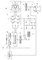
- a pump control unit provided in a vehicle including a hydraulic pressure control ECU 1, a driver control unit 10 (an example of a power control unit), a driver circuit 2, an electric motor M and a hydraulic pump P is configured. It is done.
- the engine of a vehicle such as a passenger car is equipped with a valve opening / closing timing control mechanism and a hydraulic operating device 3 such as a hydraulic actuator.
- the driver control unit 10 supplies the electric motor M by pulse width modulation. Power to control the drive rotation of the hydraulic pump P.
- a vehicle in which idling stop control is performed can be exemplified.
- an engine-driven main hydraulic pump (not shown) and an oil passage system provided in parallel with the hydraulic pump P of the present invention are provided, and hydraulic oil is supplied from this oil passage system.
- a hydraulic operating device 3 is provided.
- the pump control unit of the present invention controls the electric motor M to drive the hydraulic pump P, and supply of hydraulic fluid to the hydraulic operating device 3 even when the engine is stopped. To achieve.
- a hybrid vehicle provided with a hydraulic pump P controlled by the electric motor M can be exemplified.
- the hybrid motor is not only supplied with the hydraulic fluid to the hydraulic actuator 3 when the engine is stopped, but also a part of the hydraulic fluid from the hydraulic pump P is cooled by the oil cooler to cool the hybrid motor.
- the pump control unit shown in FIG. 1 is provided with a main oil passage 4 for supplying hydraulic oil from the hydraulic pump P to the hydraulic operating device 3, and the main oil passage 4 has a relief valve 5 for releasing the pressure when the pressure of the hydraulic oil rises.
- An oil passage system is provided which supplies hydraulic oil not supplied to the hydraulic actuator 3 as a lubricating oil to a main gallery (not shown) of the engine.
- the main oil passage 4 is provided with a hydraulic pressure sensor Sp that detects the hydraulic pressure of the hydraulic fluid delivered from the hydraulic pump P, and the detection result of the hydraulic pressure sensor Sp is fed back to the hydraulic pressure control ECU 1.
- the electric motor M is configured as a sensorless brushless DC motor having a plurality of excitation coils 6 and a rotor 7 driven and rotated by the action of a magnetic field from the excitation coils 6.
- the electric motor M is controlled by a driver control unit 10.
- the hydraulic control ECU 1 sets a target hydraulic pressure according to the rotational speed of the engine and the traveling condition of the vehicle, sets target duty ratio information for obtaining the hydraulic pressure, and outputs the target duty ratio information to the driver control unit 10.
- the driver control unit 10 generates a PWM signal based on the target duty ratio information, and controls a plurality of power control elements such as a plurality of power transistors and MOSFETs of the driver circuit 2 to drive the electric motor M.
- the pump control unit includes a shunt resistor Rs that converts the current supplied to the driver circuit 2 into a voltage signal, and generates a detection voltage signal having a voltage division ratio corresponding to the duty ratio from the voltage signal from the shunt resistor Rs.
- a voltage dividing ratio setting circuit A configured of three voltage dividing resistors R1, R2, and R3 and a capacitor C is provided.
- the driver control unit 10 performs control to change the duty ratio of the PWM signal output from the driver control unit 10 to the driver circuit 2 by acquiring the detection voltage from the voltage division ratio setting circuit A.
- the configuration and operation of the driver control unit 10 will be described below.
- the driver control unit 10 includes a duty ratio setting unit 11, a pulse generation circuit 12, a PWM signal generation unit 13, a signal correction circuit 14 (an example of a power correction unit), a comparator 15, and a reference voltage generation circuit 16.
- a duty ratio setting unit 11 a pulse generation circuit 12
- a PWM signal generation unit 13 a pulse generation circuit 14
- a comparator 15 a comparator 15
- a reference voltage generation circuit 16 a comparator 15 and a reference voltage generation circuit 16.
- the duty ratio setting unit 11 applies target duty ratio information output from the hydraulic pressure control ECU 1 to the PWM signal generation unit 13 as a threshold by D / A conversion processing.
- the pulse generation circuit 12 generates a drive pulse signal of a set period and supplies the drive pulse signal to the PWM signal generation unit 13.
- the PWM signal generation unit 13 has a comparator (not shown) that generates a PWM signal based on the threshold value from the duty ratio setting unit 11 and a sawtooth signal generated by an internal oscillation circuit (not shown). ing. Further, the PWM signal generation unit 13 includes an output circuit (not shown) which outputs the PWM signal to a plurality of power control elements of the driver circuit 2 in a carrier cycle synchronized with the drive pulse signal from the pulse generation circuit 12 A correction circuit (not shown) is provided to change the threshold based on the correction signal from the signal correction circuit 14 to shorten the ON time of the PWM signal.
- the signal correction circuit 14 supplies a correction signal to the PWM signal generation unit 13 when the output signal is output from the comparator 15. By receiving this correction signal, the PWM signal generator 13 adjusts the threshold to shorten the ON time of the PWM signal.
- the reference voltage from the reference voltage generation circuit 16 is applied to one input terminal, and the detection voltage signal from the voltage division ratio setting circuit A is applied to the other input terminal.
- the voltage division ratio setting circuit A generates a detection voltage signal having a voltage division ratio corresponding to the duty ratio from the voltage signal from the shunt resistor Rs.
- the comparator 15 outputs an output signal from the output terminal.
- the driver control unit 10 is configured to include a clock generation circuit and a counter, and the duty ratio setting unit 11 is configured to give the number of clocks indicating the ON time of the PWM signal. Further, the PWM signal generation unit 13 generates a waveform of a PWM signal which is in the ON state only for the time when the clock number corresponding to the ON time is counted and is OFF for the time when the clock number corresponding to the OFF time is counted. To configure. In this alternative embodiment, the duty ratio of the PWM signal can be changed by logic such as a clock generation circuit, a counter, a gate or a register.
- the driver control unit 10 is also provided with a start control circuit that increases the ON time of the duty ratio of the PWM signal from a low value to a high value when the electric motor M starts.
- a start control circuit that increases the ON time of the duty ratio of the PWM signal from a low value to a high value when the electric motor M starts.
- the signal correction circuit 14 is configured by a switching element interposed in a signal path output from the PWM signal generation unit 13 to the driver circuit 2, and the switching element is configured to be turned off by the output signal from the comparator 15.
- the PWM signal is cut off at the timing when the output signal is output from the comparator 15, so that the ON time can be shortened.
- the signal correction circuit 14 changes the count value corresponding to the ON time. By performing the processing, the change of the duty ratio is realized.
- the voltage dividing ratio setting circuit A has three resistors of voltage dividing resistors R1, R2 and R3 between the position where the voltage signal of the shunt resistor Rs acts and the ground position (between the terminals of the shunt resistor Rs).
- the capacitor C is connected in series in this order and in parallel with the voltage-dividing resistor R3 on the most ground side. From such a configuration, based on the voltage signal from the shunt resistor Rs, a detection voltage signal having a voltage dividing ratio corresponding to the duty ratio can be created, and can be taken out from an intermediate position between the voltage dividing resistor R1 and the voltage dividing resistor R2.
- this voltage division ratio setting circuit A when the duty ratio of the PWM signal is low (when the ON time is short), the capacitor C repeats charging and discharging, so the voltage signal from the shunt resistor Rs flows to the capacitor C and the ground side The value of the current flowing through the voltage dividing resistor R3 is reduced, and the rise of the detection voltage signal applied to the input terminal of the comparator 15 is suppressed. That is, the voltage signal from the shunt resistor Rs is dominantly divided by the two voltage dividing resistors R1 and R2.
- the voltage dividing ratio setting circuit A may be configured by providing a processing device for reducing the size. With this configuration, there is no need to provide a voltage dividing resistor, and the detection accuracy is not affected by the accuracy of the voltage dividing resistor.
- a servo motor that does not have the capacitor C and is configured with a variable resistor on the ground side (for example, R3 in FIG. 1) and operates the variable resistor.
- the control system may be configured to control the actuator so that the resistance value of the voltage dividing resistor, which is a variable resistor, decreases as the duty ratio decreases.
- it is also possible to set the operation mode of the actuator so as to set the characteristic that requires the relationship between the change in the voltage division resistance to the change in the duty ratio.
- the capacitor C is not provided, and the voltage division resistor on the ground side (for example, R3 in FIG. 1) is configured by a digital potentiometer, and is set by the digital potentiometer as the duty ratio is lower.
- a control system that lowers the resistance value may be provided.
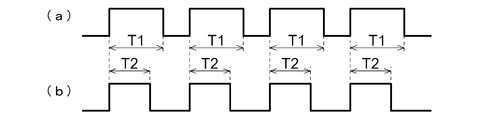
- the oil pressure control ECU 1 performs control to set the target duty ratio to 100% to obtain a target oil pressure with the hydraulic pump P. That is, when the electric motor M is rotated steadily, a current with a duty ratio of 100% is supplied as a PWM signal. Thereby, the capacitor C of the voltage dividing ratio setting circuit A is maintained in the charged state, and when the current flowing to the exciting coil 6 increases and the voltage signal from the shunt resistor Rs rises, the voltage dividing ratio setting circuit A to the comparator 15 The detection voltage signal applied to the input terminal of the signal sensitively rises. Therefore, for example, as shown in FIG.
- the ON time of the PWM signal of T1 is shortened to T2 so that the ON time of the PWM signal is shortened to T2, and the driving speed of the electric motor M is reduced.
- the rise is suppressed, and the disadvantage that the oil pressure of the hydraulic fluid pumped from the hydraulic pump P excessively rises is suppressed.
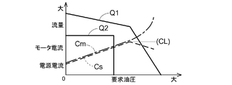
- FIG. 3 shows a graph in which the required oil pressure is taken on the horizontal axis and the flow rates Q1 and Q2 of hydraulic fluid, the motor current Cm, and the power supply current Cs are taken on the vertical axis in the configuration without the relief valve 5.
- the motor current Cm and the power supply current Cs rise upward to the right as the required hydraulic pressure rises.
- the motor current Cm and the power supply current Cs correspond to the duty ratio, and after reaching the power supply current limit value CL (the duty ratio is 100%), the ON time of the duty ratio is shortened as described above, and the power supply current Cs decreases with falling to the right, and the motor current Cm increases under the influence of the exciting coil 6.
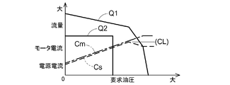
- FIG. 4 shows a graph in which the required oil pressure is taken on the horizontal axis and the flow rates Q1 and Q2 of hydraulic fluid, the motor current Cm and the power supply current Cs are taken on the vertical axis in the configuration provided with the relief valve 5.
- the relief pressure of the relief valve 5 is set so as to release the pressure of the hydraulic fluid at a pressure slightly above the upper limit of the required hydraulic pressure (required pressure).
- the motor current Cm and the power supply current Cs rise upward to the right as the required hydraulic pressure rises.
- the motor current Cm and the power supply current Cs correspond to the duty ratio, and after reaching the power supply current limit value CL, the ON time of the duty ratio is shortened as described above, and the power supply current Cs decreases in the downward direction.
- the motor current Cm increases under the influence of the exciting coil 6.
- the required oil amount Q2 is secured when the required oil pressure rises, and the flow rate Q1 of the hydraulic oil decreases in the downward direction as the required oil pressure increases, and further after relief valve 5 reaches the relief pressure. It becomes steep and declines at the bottom.
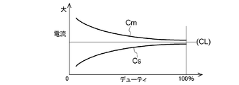
- FIG. 5 shows a graph in which the duty ratio is plotted on the horizontal axis and the current is plotted on the vertical axis.
- the motor current Cm decreases. That is, the motor coil Cm has a large value because it stores current in the exciting coil 6 of the transmission motor at low speed rotation, but decreases as the power supply current Cs rises, and when the duty ratio reaches 100%
- the power supply current Cs and the motor current Cm have approximate values.
- the present invention can be used in an apparatus in which the rotational speed of an electric motor for driving a pump is controlled by setting the duty ratio of a PWM signal.
Landscapes
- Engineering & Computer Science (AREA)
- Power Engineering (AREA)
- Mechanical Engineering (AREA)
- General Engineering & Computer Science (AREA)
- Computer Hardware Design (AREA)
- Control Of Motors That Do Not Use Commutators (AREA)
- Control Of Positive-Displacement Pumps (AREA)
Priority Applications (2)
| Application Number | Priority Date | Filing Date | Title |
|---|---|---|---|
| CN201280058517.5A CN103958894B (zh) | 2011-11-30 | 2012-11-15 | 泵控制单元 |
| US14/359,072 US9163625B2 (en) | 2011-11-30 | 2012-11-15 | Current limited pulse width modulation controlled motor |
Applications Claiming Priority (2)
| Application Number | Priority Date | Filing Date | Title |
|---|---|---|---|
| JP2011-262501 | 2011-11-30 | ||
| JP2011262501A JP5557056B2 (ja) | 2011-11-30 | 2011-11-30 | ポンプ制御ユニット |
Publications (1)
| Publication Number | Publication Date |
|---|---|
| WO2013080805A1 true WO2013080805A1 (ja) | 2013-06-06 |
Family
ID=48535271
Family Applications (1)
| Application Number | Title | Priority Date | Filing Date |
|---|---|---|---|
| PCT/JP2012/079657 Ceased WO2013080805A1 (ja) | 2011-11-30 | 2012-11-15 | ポンプ制御ユニット |
Country Status (4)
| Country | Link |
|---|---|
| US (1) | US9163625B2 (enExample) |
| JP (1) | JP5557056B2 (enExample) |
| CN (1) | CN103958894B (enExample) |
| WO (1) | WO2013080805A1 (enExample) |
Cited By (1)
| Publication number | Priority date | Publication date | Assignee | Title |
|---|---|---|---|---|
| CN113958390A (zh) * | 2021-10-15 | 2022-01-21 | 潍柴动力股份有限公司 | 一种尿素泵建压占空比自学习的方法 |
Families Citing this family (4)
| Publication number | Priority date | Publication date | Assignee | Title |
|---|---|---|---|---|
| BR112012023070A2 (pt) * | 2010-03-18 | 2019-09-24 | Axia Acquisition Corp | ajuste de fluxo de bomba em ferramenta. |
| WO2019202831A1 (ja) * | 2018-04-19 | 2019-10-24 | 株式会社村田製作所 | ポンプ装置 |
| CN113294323B (zh) * | 2021-05-25 | 2023-04-18 | 上海飞象健康科技有限公司 | 流量恒定控制方法、计算机可读存储介质及冲牙器 |
| KR102370626B1 (ko) * | 2021-12-20 | 2022-03-03 | 이창수 | 듀얼 펌프의 스마트 컨트롤 시스템 |
Citations (5)
| Publication number | Priority date | Publication date | Assignee | Title |
|---|---|---|---|---|
| JP2001268935A (ja) * | 2000-03-24 | 2001-09-28 | Daikin Ind Ltd | 空気調和機の駆動回路 |
| JP2004309386A (ja) * | 2003-04-09 | 2004-11-04 | Toyota Motor Corp | 電流検出装置 |
| JP2005094938A (ja) * | 2003-09-18 | 2005-04-07 | Matsushita Electric Ind Co Ltd | インバータ装置 |
| JP2006325332A (ja) * | 2005-05-19 | 2006-11-30 | Matsushita Electric Ind Co Ltd | インバータ装置 |
| JP2008271628A (ja) * | 2007-04-16 | 2008-11-06 | Jtekt Corp | 電流検出回路 |
Family Cites Families (9)
| Publication number | Priority date | Publication date | Assignee | Title |
|---|---|---|---|---|
| US3586990A (en) * | 1969-10-30 | 1971-06-22 | Gte Automatic Electric Lab Inc | Low-pass active parallel-t filter with zero source impedance |
| ES2433647T3 (es) | 2001-09-29 | 2013-12-12 | Daikin Industries, Ltd. | Procedimiento para la detección de la corriente de fase, procedimiento de control de inversor, procedimiento de control de motor y aparatos utilizados en estos procedimientos |
| JP2004353624A (ja) | 2003-05-30 | 2004-12-16 | Aisin Seiki Co Ltd | 電動液体ポンプの制御方法および装置 |
| JP4065441B2 (ja) * | 2004-07-28 | 2008-03-26 | 松下電器産業株式会社 | モータ駆動装置及びモータ駆動方法 |
| GB0502149D0 (en) * | 2005-02-02 | 2005-03-09 | Boc Group Inc | Method of operating a pumping system |
| JP2008092784A (ja) * | 2006-07-28 | 2008-04-17 | Mitsuba Corp | ブラシレスモータの駆動装置及びブラシレスモータの始動方法並びにブラシレスモータのロータ停止位置検出方法 |
| US7956561B2 (en) * | 2007-05-28 | 2011-06-07 | Denso Corporation | Rotor position sensing system of brushless motor |
| JP4884355B2 (ja) * | 2007-11-26 | 2012-02-29 | オムロンオートモーティブエレクトロニクス株式会社 | 多相電動機の制御装置 |
| JP5328592B2 (ja) | 2009-10-02 | 2013-10-30 | オムロンオートモーティブエレクトロニクス株式会社 | モータ駆動装置 |
-
2011
- 2011-11-30 JP JP2011262501A patent/JP5557056B2/ja active Active
-
2012
- 2012-11-15 CN CN201280058517.5A patent/CN103958894B/zh active Active
- 2012-11-15 US US14/359,072 patent/US9163625B2/en active Active
- 2012-11-15 WO PCT/JP2012/079657 patent/WO2013080805A1/ja not_active Ceased
Patent Citations (5)
| Publication number | Priority date | Publication date | Assignee | Title |
|---|---|---|---|---|
| JP2001268935A (ja) * | 2000-03-24 | 2001-09-28 | Daikin Ind Ltd | 空気調和機の駆動回路 |
| JP2004309386A (ja) * | 2003-04-09 | 2004-11-04 | Toyota Motor Corp | 電流検出装置 |
| JP2005094938A (ja) * | 2003-09-18 | 2005-04-07 | Matsushita Electric Ind Co Ltd | インバータ装置 |
| JP2006325332A (ja) * | 2005-05-19 | 2006-11-30 | Matsushita Electric Ind Co Ltd | インバータ装置 |
| JP2008271628A (ja) * | 2007-04-16 | 2008-11-06 | Jtekt Corp | 電流検出回路 |
Cited By (2)
| Publication number | Priority date | Publication date | Assignee | Title |
|---|---|---|---|---|
| CN113958390A (zh) * | 2021-10-15 | 2022-01-21 | 潍柴动力股份有限公司 | 一种尿素泵建压占空比自学习的方法 |
| CN113958390B (zh) * | 2021-10-15 | 2022-08-23 | 潍柴动力股份有限公司 | 一种尿素泵建压占空比自学习的方法 |
Also Published As
| Publication number | Publication date |
|---|---|
| CN103958894B (zh) | 2015-07-22 |
| US20140286793A1 (en) | 2014-09-25 |
| CN103958894A (zh) | 2014-07-30 |
| US9163625B2 (en) | 2015-10-20 |
| JP2013113273A (ja) | 2013-06-10 |
| JP5557056B2 (ja) | 2014-07-23 |
Similar Documents
| Publication | Publication Date | Title |
|---|---|---|
| US10291110B2 (en) | Driving circuit for switching element and power conversion system | |
| US9000698B2 (en) | Motor controlling apparatus | |
| US9450533B2 (en) | Rotation-speed-controlled fan with control of the power consumption of the electric motor | |
| WO2013080805A1 (ja) | ポンプ制御ユニット | |
| CN107246382B (zh) | 车载用电动压缩机的控制方法 | |
| EP2445111A2 (en) | Brushless motor driving circuit | |
| JP2009072051A (ja) | 充電システムおよび車両用発電制御装置 | |
| CN102966449A (zh) | 用于调节发电机组的方法 | |
| JP4678545B2 (ja) | モータ駆動装置 | |
| US20170218875A1 (en) | Fluid supply device | |
| JP2010233301A (ja) | センサレス・ブラシレスモータ制御装置及びそれを用いた電動流体ポンプ | |
| KR20080083696A (ko) | 모터 부하를 모니터링하기 위한 시스템 및 방법 | |
| JP2007282328A (ja) | 発電制御システム | |
| US12404853B2 (en) | Electric oil pump for automobile transmission clutch engagement, electric oil pump control method for automobile transmission clutch engagement, vehicle, and vehicle electric oil pump for automobile transmission clutch engagement | |
| KR100453666B1 (ko) | 차량용 교류발전기의 전압제어장치 | |
| EP1699130B1 (en) | Inverter unit | |
| US9083277B2 (en) | Control device for an electric motor | |
| JP4218317B2 (ja) | 電動流体ポンプ装置 | |
| KR100994109B1 (ko) | 하이브리드 차량용 외장형 오일펌프 제어장치 | |
| CN111379693B (zh) | 电动泵 | |
| JP5716311B2 (ja) | 電動ポンプユニット | |
| JP2015144525A (ja) | 車両用電源装置 | |
| EP2843831A2 (en) | Motor drive unit | |
| US11041472B2 (en) | Motor driving device | |
| JP5450248B2 (ja) | 電子制御装置 |
Legal Events
| Date | Code | Title | Description |
|---|---|---|---|
| 121 | Ep: the epo has been informed by wipo that ep was designated in this application |
Ref document number: 12852530 Country of ref document: EP Kind code of ref document: A1 |
|
| WWE | Wipo information: entry into national phase |
Ref document number: 14359072 Country of ref document: US |
|
| NENP | Non-entry into the national phase |
Ref country code: DE |
|
| 122 | Ep: pct application non-entry in european phase |
Ref document number: 12852530 Country of ref document: EP Kind code of ref document: A1 |