WO2013080652A1 - 接触式内部温度計 - Google Patents
接触式内部温度計 Download PDFInfo
- Publication number
- WO2013080652A1 WO2013080652A1 PCT/JP2012/075418 JP2012075418W WO2013080652A1 WO 2013080652 A1 WO2013080652 A1 WO 2013080652A1 JP 2012075418 W JP2012075418 W JP 2012075418W WO 2013080652 A1 WO2013080652 A1 WO 2013080652A1
- Authority
- WO
- WIPO (PCT)
- Prior art keywords
- temperature sensor
- measurement
- bypass
- contact
- temperature
- Prior art date
- Legal status (The legal status is an assumption and is not a legal conclusion. Google has not performed a legal analysis and makes no representation as to the accuracy of the status listed.)
- Ceased
Links
Images



Classifications
-
- G—PHYSICS
- G01—MEASURING; TESTING
- G01K—MEASURING TEMPERATURE; MEASURING QUANTITY OF HEAT; THERMALLY-SENSITIVE ELEMENTS NOT OTHERWISE PROVIDED FOR
- G01K7/00—Measuring temperature based on the use of electric or magnetic elements directly sensitive to heat ; Power supply therefor, e.g. using thermoelectric elements
- G01K7/42—Circuits effecting compensation of thermal inertia; Circuits for predicting the stationary value of a temperature
-
- G—PHYSICS
- G01—MEASURING; TESTING
- G01K—MEASURING TEMPERATURE; MEASURING QUANTITY OF HEAT; THERMALLY-SENSITIVE ELEMENTS NOT OTHERWISE PROVIDED FOR
- G01K13/00—Thermometers specially adapted for specific purposes
- G01K13/20—Clinical contact thermometers for use with humans or animals
Definitions
- the present invention relates to a contact type internal thermometer.
- thermometer In various situations, there is a demand for measuring the internal temperature, not the surface temperature of a measurement object, quickly, accurately, and simply (ie, non-invasively).
- a typical example of such a requirement is measurement of body temperature of a living body including a human body.
- body temperature of a living body including a human body.
- the measurement target is a human body, generally hold the thermometer in a place where heat is difficult to escape to the outside, such as under the tongue or under the arm, and read the thermometer after the thermometer and human body are in thermal equilibrium.
- thermometers for measuring the internal temperature of the human body quickly and accurately have been proposed.
- Patent Document 1 describes an electronic thermometer having first temperature measuring means and second temperature measuring means sandwiching a heat insulating material, and variable temperature heating means for heating the first temperature measuring means.
- This electronic thermometer measures the temperature at the first temperature measuring means while measuring the temperature of the part on the measured object side with the second temperature measuring means. Then, the temperature of the first temperature measuring means is changed by the variable temperature heating means, and a plurality of measurements are performed while preventing the thermal equilibrium state, and the inverse problem of the heat conduction equation is solved based on the obtained result. To calculate the internal temperature.
- Patent Document 2 includes at least two sets of a first temperature sensor that is in contact with the body surface and a second temperature sensor that is disposed with a heat insulating material interposed between the first temperature sensor and each set.
- the non-heating type depth thermometer from which the heat resistance value of the heat insulating material in is different is described.
- This non-heating type deep thermometer solves the simultaneous heat conduction equation from the temperature measurement result of each temperature sensor in the steady state, and obtains the deep body temperature.
- thermometer When the contact-type internal thermometer requires variable temperature heating means, that is, a heater as in Patent Document 1 described above, a portable contact-type internal temperature that requires high power consumption and small size is required. Not suitable for the total. In consideration of bringing the thermometer into contact with the human body surface, it is not preferable to mount a heater.
- the present invention has been made in view of such circumstances, and a problem to be solved is to provide a contact type internal thermometer capable of measuring the internal temperature of a measurement object quickly, accurately and simply.
- thermometer which measures the internal temperature of a human body
- contact-type internal thermometer which this invention makes object is limited to this. It can be applied to any measurement object that needs to measure its internal temperature non-invasively regardless of whether it is living or inanimate.
- a first measurement surface side temperature sensor is arranged on the measurement surface to be brought into contact with the measurement target surface of the measurement object to calculate the internal temperature of the measurement object, and the measurement surface side of the first thermal resistor.
- a heat flux that passes through the first temperature sensor stack in a steady state and a heat flow that passes through the second temperature sensor have at least a second temperature sensor stack in which the second back surface temperature sensor is disposed.
- the bundles are configured to be different, and form bypass channels that are thermal connections between the measurement object and the first back surface temperature sensor and between the measurement object and the second back surface temperature sensor.
- a bypass member for connecting and blocking the bypass flow path; Based on the measurement results of the path flow path connection cutoff mechanism, the first measurement surface side temperature sensor, the first back surface temperature sensor, the second measurement surface side temperature sensor, and the second back surface temperature sensor.
- An internal temperature calculator that calculates an internal temperature of the measurement object.
- the thermal resistance of the bypass member is a contact-type internal thermometer smaller than the thermal resistance of the first thermal resistor and the second thermal resistor.
- (1) or (2) it has a connection detection part for detecting whether or not the bypass flow path is connected, and the internal temperature calculation part is connected to the bypass flow path by the connection detection part.
- a contact-type internal thermometer that calculates the internal temperature of the measurement object after the first temperature sensor multilayer body and the second temperature sensor multilayer body reach a steady state after detecting that they are connected.
- a shut-off timing detection section that detects a timing at which the bypass flow path should be shut off, and the shut-off timing detection section And a shutoff timing notifying unit for notifying the user that the timing for shutting off the bypass flow path has been detected.
- a shut-off timing detection section that detects a timing at which the bypass flow path should be shut off, and the shut-off timing detection section
- a contact-type internal thermometer comprising: a shut-off portion that shuts off the bypass flow path when the timing at which the bypass flow path should be shut off is detected by
- the internal temperature calculation unit further includes the first temperature sensor laminate and the first A contact-type internal thermometer that calculates the internal temperature of the measurement object after the temperature sensor stack of 2 reaches a steady state.
- the bypass member includes a temperature sensitive blocking mechanism that blocks the bypass flow path according to a temperature rise of the bypass member.
- the bypass channel connection blocking mechanism includes a push button operated by a user, and the bypass channel is connected when the user presses the push button.
- a contact-type interior that includes an elastic support structure that supports the measurement surface movably with respect to the case, and the bypass channel is connected by a user pressing the measurement surface against the measurement object. thermometer.
- the bypass member includes a first bypass member that thermally connects the measurement object and the first back surface temperature sensor, and the measurement object. And a second bypass member thermally connected between the object and the second back surface temperature sensor and thermally isolated from the first bypass member, provided on the measurement surface, A first probe thermally coupled to the measurement surface side temperature sensor, a second probe provided on the measurement surface and thermally coupled to the second measurement surface side temperature sensor, and the measurement surface A third probe provided and thermally coupled to the first bypass member; and a fourth probe provided on the measurement surface and thermally coupled to the second bypass member; The first probe, the second probe, the third probe Lobe and the fourth probe contact type internal thermometer that is thermally isolated from each other.
- a contact type internal thermometer capable of measuring the internal temperature of the measurement object quickly, accurately and simply is provided.
- the first temperature sensor laminate and the second temperature sensor laminate quickly reach a steady state.
- the internal temperature of the measurement object can be accurately calculated.
- the user can block the bypass flow path at an appropriate timing.
- the bypass flow path can be blocked at an appropriate timing without requiring the user to perform the operation of blocking the bypass flow path.
- the internal temperature of the measurement object can be accurately calculated.
- the bypass channel can be shut off autonomously without the user performing a blocking operation of the bypass channel or performing control for blocking the bypass channel.
- the user can connect the bypass flow path with a simple operation.
- the measurement error due to the heat flow between the first temperature sensor laminate and the second temperature sensor laminate can be greatly reduced.
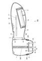
- FIG. 3 is a schematic sectional view of a contact-type internal thermometer taken along line III-III in FIG. 1.
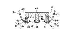
- FIG. 4 is an enlarged cross-sectional view in the vicinity of the measurement head in FIG. 3. It is a figure which shows the equivalent thermal circuit of the measurement part provided in the measurement head of the contact-type internal thermometer which concerns on the 1st Embodiment of this invention.
- FIG. 8 is a schematic sectional view of a contact-type internal thermometer taken along line VIII-VIII in FIG. 7.
- FIG. 8 is a schematic cross-sectional view of the contact-type internal thermometer according to the third embodiment of the present invention taken along line VIII-VIII in FIG.
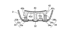
- FIG. 10 is an enlarged cross-sectional view of the vicinity of the measurement head in FIG.
- FIG. 13 is an enlarged cross-sectional view of the vicinity of the measurement head taken along line XIII-XIII in FIG.
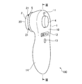
- FIG. 1 is an external view of a contact type internal thermometer 100 according to the first embodiment of the present invention viewed from the back side
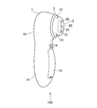
- FIG. 2 is a view of the contact type internal thermometer 100 according to the same embodiment from the measurement surface side. It is an external view.
- the contact-type internal thermometer is a thermometer, and means a thermometer that measures the internal temperature by bringing it into contact with the surface to be measured.
- the internal temperature means not the surface temperature of the measurement target but the temperature inside the region that is considered to be a substantially constant temperature heat source.
- the heat source is substantially constant temperature when the heat capacity inside the measurement target is large, or when heat is constantly supplied to the measurement target, the measurement with the contact-type internal thermometer is practically applied to that temperature. It means that it is considered that there is no influence. For example, when the measurement target is a living body, heat is always supplied from the trunk by the blood flow, which corresponds to the latter.
- the contact-type internal thermometer 100 shown in the present embodiment is portable as shown in the figure, and the measurement head 2 is attached to the tip of the case 1.
- the measuring head 2 is provided so as to protrude from the case 1, and the tip thereof is a substantially flat measuring surface 20.
- the internal temperature is measured by making this measurement surface 20 contact the to-be-measured surface of a measuring object, for example, skin.
- a substantially circular first probe 30, second probe 31, and third probe 32 are arranged in series along the longitudinal direction of the contact-type internal thermometer 100 on the surface of the measurement surface 20, as shown in FIG. Has been placed.
- the arrangement of the first probe 30, the second probe 31, and the third probe 32 is arbitrary, and the arrangement direction is not necessarily along the longitudinal direction of the contact-type internal thermometer 100. Furthermore, it is not necessary to arrange each probe in series, such as arranging each probe at a position where it becomes the vertex of an equilateral triangle.
- a lamp 11, a push button 4, a display unit 12, and a buzzer 13 are provided on the back surface 10, which is the surface opposite to the measurement surface 20 of the case 1.
- the direction in which the measurement surface 20 faces is referred to as the measurement surface side
- the direction in which the back surface, which is the opposite direction, faces is referred to as the back side.
- the case 1 has a long and rounded shape, and forms a grip 14 that the user has in his hand.
- a battery lid 15 is provided on the measurement surface side of the grip 14 of the case 1, and a battery serving as a power source for the contact type internal thermometer 100 is accommodated therein.
- an intake hole 16 is provided at an appropriate position of the case 1, here the position shown in FIG. 2, and an exhaust hole 21 is provided on the side surface of the measurement head 2, so that each internal space communicates with the outside air.
- Case 1 and measuring head 2 are connected by a support ring 5.
- the design of the contact type internal thermometer 100 shown in FIGS. 1 and 2 is an example. Such a design may be appropriately changed in consideration of its main use and marketability. Further, the arrangement of each component may be arbitrarily selected within a range that does not impair its function.
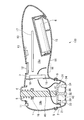
- FIG. 3 is a schematic cross-sectional view of the contact-type internal thermometer 100 taken along line III-III in FIG.
- the case 1 is preferably a hollow molded product made of any synthetic resin such as ABS resin, and various parts constituting the contact-type internal thermometer 100 are integrally accommodated therein.
- a battery 6 and a circuit board 17 are accommodated in the grip 14.
- Various electronic components such as a controller (not shown) are mounted on the circuit board 17 and receive power from the battery 6 to supply power to all components that require power. In addition, the operation is controlled.
- the battery 6 shown in the figure is a commercially available AAA type (referred to as AAA in the United States) dry battery, but the type thereof may be arbitrary, such as a button type or a square type, or a primary type.
- the battery and secondary battery may be optional. Note that wiring for electrically connecting each component and the circuit board 17 is omitted because it is complicated to illustrate.
- the lamp 11 is preferably a light emitting diode capable of emitting multiple colors, and is lit to notify the user of the state of the contact type internal thermometer 100.
- the display unit 12 is a liquid crystal display device in the present embodiment, and is used to notify the user of the measurement result of the contact-type internal thermometer 100 in a manner as shown in FIG. Of course, any other information such as the remaining amount of the battery 6 may be displayed on the display unit 12. Alternatively, the state of the contact type internal thermometer 100 may be displayed together and the lamp 11 may be omitted.
- the buzzer 13 is a general electronic buzzer in this embodiment, and is for notifying the user of the state of the contact-type internal thermometer 100 by a beep sound. The form of the buzzer 13 is also arbitrary, and a speaker may be provided to notify by voice or melody. Alternatively, the buzzer 13 may be omitted only for notification by the lamp 11 and / or the display unit 12.
- a partition wall 18 is provided inside the case 1, and the inside of the case 1 is partitioned into a grip space 19a and a head space 19b.
- the partition wall 18 is provided with an opening, and the blower 7 is attached so as to close the opening. The function of the blower 7 will be described later.
- the measuring head 2 is attached to the tip of the case 1 through a support ring 5.
- the support ring 5 is preferably made of a material having elasticity such as silicon rubber or its foam and having excellent heat insulation properties, and allows slight movement of the measuring head 2 with respect to the case 1, and from the measuring head 2 to the case.
- the heat transfer to 1 is cut off. This is because when the measurement surface 20 is brought into contact with the measurement object, the measurement surface 20 is surely brought into close contact with the measurement object, and the measurement error is caused by heat flowing from the measurement head 2 to the case 1. This is to prevent the occurrence of the above.
- the support ring 5 is not an essential configuration, there is no problem in the close contact between the measurement surface 20 and the measurement object, and the measurement head 2 is a material having a sufficiently low thermal conductivity, and there is no practical problem. This may be omitted, and the measurement head 2 may be directly fixed to the case 1 or both may be integrally formed. Further, the shape of the support ring 5 is not limited to a ring shape, and an arbitrary shape may be used.
- the measuring head 2 is preferably formed of a material having a stable shape, low thermal conductivity, and low specific heat.
- a material having a stable shape, low thermal conductivity, and low specific heat for example, rigid foamed urethane or rigid foamed vinyl chloride is suitably used.
- the material is not particularly limited in this respect as long as there is no practical problem, and any material may be used.
- the measurement surface 20 of the measurement head 2 is provided with openings at positions corresponding to the first probe 30, the second probe 31, and the third probe 32, and each probe slightly protrudes from the measurement surface 20. It is attached as follows.
- Each probe is preferably made of a material having high thermal conductivity, and is made of metal in this embodiment.
- the material of each probe preferably has corrosion resistance, and aluminum or stainless steel is suitable as the metal material.
- the measuring head 2 itself is made of a material having low thermal conductivity, the first probe 30, the second probe 31, and the third probe 32 are thermally isolated from each other. It becomes.
- the first temperature sensor laminate 33 is provided on the back side of the first probe 30 and both are thermally coupled to each other. Further, a second temperature sensor laminate 34 is provided on the back side of the second probe 31, and both are thermally coupled to each other. Details of the first temperature sensor stacked body 33 and the second temperature sensor stacked body 34 will be described later.
- the temperature sensor stack is provided with two of the first temperature sensor stack 33 and the second temperature sensor stack 34. However, the temperature sensor stack may be used for error dispersion or for backup purposes in the event of a failure. Three or more sensor stacks may be provided.
- the push button 4 is arranged on the back surface 10 of the case 1 so that it can be pressed to the measurement surface side. In this embodiment, it is urged to the back side by a spring 8 provided on a spring seat 19 provided in the case 1.
- the structure for supporting and urging the push button 4 is not limited to the structure shown here, and any structure can be used as long as a bypass member 42 described later can be pressed against the measurement surface side. There may be.
- a pressing rod 40 extends from the push button 4 toward the measurement surface, and a bypass member 42 is attached to the tip of the pressing rod 40 via a heat insulating material 41.
- the bypass member 42 is preferably made of a material having high thermal conductivity, and is made of metal in the present embodiment.
- the cross-sectional shape of the pressing rod 40 is not particularly limited, and may be any shape such as a solid or hollow cylinder or prism, or a cross shape.
- FIG. 4 is an enlarged cross-sectional view of the vicinity of the measuring head 2 in FIG.
- the support ring 5 and the heat insulating material 41 in FIG. 3 and members located on the back side from these members are not shown.
- the first temperature sensor stacked body 33 is disposed on the measurement surface side, and contacts with the first probe 30 and is thermally coupled to the first measurement surface side temperature sensor 33a.
- the first back surface temperature sensor 33b disposed on the back surface side and the first back surface temperature sensor 33b disposed between the first back surface temperature sensor 33b and the first back surface temperature sensor 33b.
- the thermal resistor 33c is laminated.
- the second temperature sensor laminate 34 also has the same structure as that of the first temperature sensor laminate 33, and is arranged on the measurement surface side, and is in contact with the second probe 31 and thermally coupled thereto.
- the second thermal resistor 34c forming the path is laminated. Therefore, when the measurement surface 20 is brought into contact with the measurement object, heat is transferred from the measurement object to the probe 30 and the probe 31, and the heat is the first measurement surface side temperature sensor for the first temperature sensor stack 33.
- the second measurement surface side temperature sensor 34a and the second thermal resistor 34c and the 2nd back side temperature sensor 34b are passed in order, and are dissipated to air
- Each temperature sensor is connected to the circuit board 17 (see FIG. 3) by a wiring (not shown) so that the temperature in each temperature sensor can be detected.
- the heat flux passing through the first temperature sensor laminate 33 and the heat flux passing through the second temperature sensor laminate 34 are different, and at least the ratio of the thermal resistances.
- the first temperature sensor laminate 33 and the second temperature sensor laminate 34 have different heat fluxes that pass through the temperature sensor laminate when the same temperature difference is given to both ends. Configured.
- the thermal resistance of the thermal resistor 33c and the second thermal resistor 34c may be different, or a heat dissipation control member having a plate shape or other shape may be disposed on the back surface of one or both temperature sensor laminates.
- the thermal resistance of the first thermal resistor 33c and the second thermal resistor 34c may be equal, and the thermal resistance ratio is 1: 1.
- each thermal resistance can be arbitrarily selected by selecting the material or controlling the shape. Can be set to something.
- the first thermal resistor 33c and the second thermal resistor 34c are made of the same material and have the same cross-sectional cylindrical shape, and only the heights thereof are different. Yes.
- the value of the thermal resistance is proportional to the height thereof, so that the thermal resistance ratio can be easily set. Can be set arbitrarily. In the present embodiment, the ratio between the height and the thermal resistance is 1: 2. Of course, this ratio may be different.
- the bypass member 42 has columnar portions 42a, 42b, and 42c protruding toward the measurement surface side, and the columnar portions 42a and 42b are connected by a beam 42d and the columnar portions 42a and 42c are connected by a beam 42e. It has a shape.
- the push button 4 see FIG. 3
- the measurement surface side surface of the columnar portion 42a comes into contact with the rear surface side surface of the third probe 32, and the measurement surface side of the columnar portion 42b and the columnar portion 42c.
- the surfaces are in contact with the first back side temperature sensor 33b of the first temperature sensor stack 33 and the second back side temperature sensor 34b of the second temperature sensor stack 34, respectively, and the probe 32 and the first back side The temperature sensor 33b and the second back surface temperature sensor 34b are thermally connected.
- the bypass member 42 is between the measurement object and the first back surface temperature sensor 33b and between the measurement object and the second back surface temperature sensor 34b.
- a bypass flow path that is a thermal connection between them is formed.
- the bypass member 42 has the third probe 32, the first back surface temperature sensor 33b, and the second back surface temperature. Since it will be separated from the sensor 34b, it will be blocked.
- the beams 42d and 42e preferably allow some elastic deformation.
- the beams 42d and 42e preferably allow some elastic deformation.
- FIG. 5 is a diagram showing an equivalent thermal circuit of a measurement unit provided in the measurement head 2 of the contact-type internal thermometer 100 according to the present embodiment.
- Tb is an internal temperature to be measured
- T11 is a temperature in the first measurement surface side temperature sensor 33a
- T12 is a temperature in the first back surface temperature sensor 33b
- T21 is The temperature at the second measurement surface side temperature sensor 34a, T22, is the temperature at the first back surface temperature sensor 34b.
- the thermal resistance Rb is a thermal resistance when heat is transmitted from the inside of the measurement object to the first measurement surface side temperature sensor 33a and the second measurement surface side temperature sensor 34a through the first probe 30 and the second probe 31.
- the thermal resistance R1 is the thermal resistance of the first thermal resistor 33c
- the thermal resistance R2 is the thermal resistance of the second thermal resistor 34c.
- the system shown in FIG. 5 in order to obtain the internal temperature Tb by Equation 3, the system shown in FIG. 5 must be in a steady state.
- the first back surface temperature sensor 33b and the second back surface temperature sensor 34b are measured via the first heat resistor 33c and the second heat resistor 34c, respectively. Since it is thermally bonded to the object, heat from the object to be measured is difficult to be transmitted, and it takes a considerable time for the temperature to rise and reach a steady state. Therefore, in the present embodiment, in order to reduce the time for the system shown in FIG.
- the thermal conductivity of the bypass member 42 must be at least smaller than the thermal resistance of the first thermal resistor 33c and the second thermal resistor 34c.
- Procedure 1 The measurement surface 20 of the contact-type internal thermometer 100 is brought into contact with the measurement object.
- Procedure 2 Press down push button 4.
- the bypass member 42 contacts the back surface of each of the first temperature sensor stacked body 33, the second temperature sensor stacked body 34, and the third probe, and the bypass flow path is connected.
- the controller mounted on the circuit board 17 detects that the bypass channel has been formed and starts the temperature measurement operation.
- the controller notifies the user that the measurement is started by a beep sound by the buzzer 13.
- the lamp 11 is lit in an arbitrary color, for example, red, and the user is urged to keep the push button 4 depressed while the measurement surface 20 is in contact with the measurement object.
- the contact-type internal thermometer 100 is provided with a connection detection unit that detects whether or not the bypass channel is connected.
- a connection detection unit that detects whether or not the bypass channel is connected.
- an electrical switch may be provided at any position of the button 4, the pressing rod 40 or the spring 8 to detect that the button 4 is pressed down.
- any one or more of the bypass member 42, the third probe 32, the back surface of the first temperature sensor stack 33, and the back surface of the second temperature sensor stack 34 are used as electrical contacts. You may make it detect electrically that the member contacted.
- the bypass member 42 and the third probe 32 are used as contacts, and the contact between them is electrically detected.
- Procedure 3 The controller detects the timing at which the bypass flow path should be shut off, and notifies the user that the timing at which the bypass flow path should be shut off has been detected. This operation is performed by notifying the user that the first back surface temperature sensor 33b and the second back surface temperature sensor 34b are sufficiently heated, that is, close to a steady state, and pressing the button 4 down. (Ie, release the force applied to the button 4 or release the finger from the button). Thereby, the button 4 is returned to the initial position by the spring 8, and the bypass flow path is blocked.
- the shut-off timing detection unit may have any structure and may be provided with a dedicated circuit or mechanism.
- the shut-off timing is detected by software executed by a controller provided on the circuit board 17.
- the detection unit is virtually realized. That is, the controller provided on the circuit board 17 also serves as a shutoff timing detection unit.
- the criterion used for determining the timing at which the bypass flow path should be shut off is reasonable if the first back side temperature sensor 33b and the second back side temperature sensor 34b are heated to a temperature close to a steady state. Any standard may be used as long as the calculated timing can be detected. Examples of such criteria are as follows. Criteria 1: The temperature change of the first back side temperature sensor 33b and / or the second back side temperature sensor 34b is equal to or less than a predetermined threshold.
- the reference 1 is for detecting that the first back surface temperature sensor 33b and / or the second back surface temperature sensor 34b is in a substantially steady state with the bypass flow path connected thereto. In this state, it is considered that the temperature of the first back surface temperature sensor 33b and / or the second back surface temperature sensor 34b is sufficiently raised by the heat flowing in from the surface temperature of the measurement object. It is preferable to detect that the temperature change for both the first back surface temperature sensor 33b and the second back surface temperature sensor 34b is equal to or less than a predetermined threshold, but only one of them is detected. You may do it. Standard 2: The temperature of the first back surface temperature sensor 33b and / or the second back surface temperature sensor 34b is equal to or higher than a predetermined threshold value.
- This standard 2 can be adopted when the temperature range of the target to be measured by the contact-type internal thermometer 100 is generally known.
- the surface temperature is generally 35 degrees Celsius or higher and is not usually lower than that.
- the first back surface temperature sensor 33b and / or the second back surface temperature sensor 34b is heated to a temperature close to a steady state.
- This detection may be performed for both the first back surface temperature sensor 33b and the second back surface temperature sensor 34b, or only one of them may be performed.
- Criteria 3 The time during which the bypass channel is connected is equal to or longer than a predetermined time.
- This standard 3 is assumed because the heat capacities of the bypass member 42, the first back surface temperature sensor 33b, and the second back surface temperature sensor 34b are known, and the heat transfer rate of the bypass member 42 can be estimated roughly. If the bypass channel is connected for a predetermined time depending on the application, the temperature of the first back side temperature sensor 33b and the second back side temperature sensor 34b is naturally raised to a temperature close to the steady state. Is calculated. This time may be obtained theoretically or experimentally in advance.
- any of these may be used for the above criteria, or a plurality may be used in combination.
- the reference 1 is used in the contact type internal thermometer 100 according to the present embodiment.
- criteria other than the criteria 1 to 3 listed here may be used.
- the controller notifies the user that the timing at which the bypass flow path should be shut off has arrived by a beep sound from the buzzer 13, and at the same time, the lamp 11 is lit in an arbitrary color different from the previous color, for example, yellow, and the user is in the process of measuring the internal temperature and releases the push button 4 while keeping the measurement surface 20 in contact with the measurement object. Encourage them to stay in the correct state. Therefore, the buzzer 13 and the lamp 11 function as an interruption timing notification unit that notifies the user of the timing at which the bypass flow path should be interrupted.
- Step 4 The controller calculates the internal temperature of the measurement object after the first temperature sensor stacked body 33 and the second temperature sensor stacked body 34 reach a steady state after the bypass flow path is blocked. indicate. That is, the controller monitors the outputs of the first measurement surface side temperature sensor 33a, the first back surface temperature sensor 33b, the second measurement surface side temperature sensor 34a, and the second back surface temperature sensor 34b, and these temperatures. When it is detected that the temperature change of the sensor is equal to or less than a predetermined threshold value, the internal temperature is obtained from the above-described Expression 3 using the output from these temperature sensors.
- the controller measures the measurement object based on the measurement results of the first measurement surface temperature sensor 33a, the first back surface temperature sensor 33b, the second measurement surface temperature sensor 34a, and the second back surface temperature sensor 34b. It functions as an internal temperature calculation unit that calculates the internal temperature of an object. Furthermore, the internal temperature calculation unit realized by the controller detects that the bypass flow path is connected by the connection detection unit and further that the bypass flow path is blocked, and then the first temperature sensor stacked body 33 and the second temperature sensor. After the temperature sensor laminate 34 reaches a steady state, the internal temperature of the measurement object is calculated.
- the controller displays the internal temperature thus calculated on the display unit 12 as shown in FIG. Further, the user is notified that the measurement is completed by generating a beep sound by the buzzer 13 and lighting the lamp 11 in an arbitrary color different from the previous color, for example, green.
- the calculated internal temperature is displayed on the display unit 12 to notify the user, but the present invention is not limited to this, and the calculated internal temperature is stored in a memory provided in the contact-type internal thermometer 100. Alternatively, it may be output to a device external to the contact-type internal thermometer 100 by wire or wirelessly.
- the display unit 12 is not necessarily an essential configuration.
- the measurement is started by first bringing the measurement surface 20 of the contact-type internal thermometer 100 into contact with the measurement object and pressing the button 4 down. At this time, a beep sound is emitted and the lamp 11 is lit red. Subsequently, a beep sound is emitted again, and the lamp 11 is lit in yellow. Therefore, the finger is released from the button 4 and the measurement surface 20 is continuously brought into contact with the measurement object. Finally, when the beep is sounded three times and the lamp 11 is lit in green, the measurement is completed. The contact-type internal thermometer 100 is moved away from the measurement object, and the measurement result displayed on the display unit 12 is confirmed. The time required during this time depends on the measurement target and the size (heat capacity) of each part of the contact-type internal thermometer 100, but is approximately 10 seconds when the internal temperature of the human body is the measurement target.
- the measurement start notification to the user, the bypass flow path shutoff timing notification, and the various measurement end notifications are all made by the beep sound by the buzzer 13 and the lighting of the lamp 11.
- the method is not limited to the one exemplified here.
- the beep sound may be omitted or may not be uttered by the user's setting.
- how the lamp 11 is turned on, for example, how to select the emission color is arbitrary.
- This operation cools the first temperature sensor laminate 33, the second temperature sensor laminate 34, and the bypass member 42, and prepares for the next measurement. For example, when the internal temperature of a relatively high temperature measurement object is first measured and immediately after that the internal temperature of the relatively low temperature measurement object is measured, the first temperature sensor is measured at the time of the first measurement.
- the stacked body 33, the second temperature sensor stacked body 34, and the bypass member 42 may be hotter than required for the next measurement.
- the bypass member 42 may take time. Therefore, the first temperature sensor stacked body 33, the second temperature sensor stacked body 34, and the bypass member 42 are cooled to some extent for each measurement.
- the blower 7 generates an airflow that flows from the grip space 19a to the head space 19b in FIG. Therefore, the air flow induced by the blower 7 is sucked from the intake hole 16 as shown by an arrow in the figure, passes through the blower 7, and the first temperature sensor stacked body 33 and the second temperature sensor stacked body. 34 and the vicinity of the bypass member 42 are discharged from the exhaust hole 21. Therefore, the blower 7, the intake hole 16 and the exhaust hole 21 of the present embodiment cooperate to constitute a cooling mechanism that cools the first temperature sensor stacked body 33, the second temperature sensor stacked body 34, and the bypass member 42. It will be.
- the cooling mechanism may have any configuration, and the arrangement of the blower 7, the intake hole 16, and the exhaust hole 21 is arbitrary. Further, the direction of intake and exhaust may be reversed. Furthermore, the cooling target may be at least one of the first temperature sensor stacked body 33, the second temperature sensor stacked body 34, and the bypass member 42.
- the type of the blower 7 is not particularly limited, and may be a general fan or a micro blower using a piezoelectric element. Alternatively, if there is no practical problem in the measurement time for continuous measurement, the cooling mechanism itself may be omitted.
- FIG. 6 is a graph showing temperature changes of the first back side temperature sensor 33b and the second back side temperature sensor 34b in the temperature measuring operation of the contact-type internal thermometer 100 according to the present embodiment.
- the horizontal axis represents time t from the start of temperature measurement
- the vertical axis represents the temperature T of each temperature sensor.
- a curve A indicated by a thick solid line in the graph indicates a temperature change of the first back side temperature sensor 33b
- a curve B indicated by a thick broken line indicates a temperature change of the second back side temperature sensor 34b.
- the curve C shown by the thin solid line in the graph and the curve D shown by the thin broken line compare the temperature changes of the first back side temperature sensor 33b and the back side temperature sensor 34b of the 2 when the bypass member 42 is not used. It is shown for.
- the temperature of the first back surface temperature sensor 33b and the second back surface temperature sensor 34b has not yet reached the steady temperature at time t2. . This is because it takes time because heat from the object to be measured must pass through the thermal resistors 33c and 34c to be transmitted to the first back surface temperature sensor 33b and the second back surface temperature sensor 34b. It is. From the graph, in the contact-type internal thermometer 100 according to the present embodiment, the temperatures of the first back-side temperature sensor 33b and the second back-side temperature sensor 34b are quickly changed to the steady temperature after the start of the temperature measuring operation. Since the temperature is raised to a temperature close to T1s and T2s, it can be seen that the time until the first back side temperature sensor 33b and the second back side temperature sensor 34b reach the steady temperature is shortened.
- the above-described reference 1 is used.
- FIG. 7 is an external view of a contact-type internal thermometer 200 according to the second embodiment of the present invention as viewed from the back side.
- the contact-type internal thermometer 200 according to the present embodiment and the contact-type internal thermometer 100 according to the first embodiment have some differences such as the support structure of the measurement head 2 and the presence / absence of the push button 4. Apart from that, the structure is generally the same. Therefore, members and structures that are common in both embodiments are given the same reference numerals, and redundant descriptions are omitted.
- the contact-type internal thermometer 200 has a measurement head 2 attached to the tip of the case 1, the tip of which is the measurement surface 20, and the back of the case 1. 10 is provided with the lamp 11, the display unit 12, and the buzzer 13, and the grip 14 that the user holds is the same as the contact-type internal thermometer 100 in the previous embodiment.
- the push button 4 (see FIG. 1) is not provided, and the shape of the support ring 205 is also different.
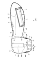
- FIG. 8 is a schematic sectional view of the contact-type internal thermometer 200 taken along line VIII-VIII in FIG.
- the support ring 205 has a cylindrical shape with a bellows cross section, and elastically supports the measurement head 2 with respect to the case 1, and in particular, the measurement head 2 can move in the back direction. ing. Then, as a result of the user of the contact-type internal thermometer 200 pressing the measurement surface 20 against the object to be measured, the support ring 205 is compressed in the cylindrical axis direction, and the measurement head 2 moves in the rear direction, the first temperature sensor The stacked body 33, the second temperature sensor stacked body 34, and the third probe 32 come into contact with the bypass member 42 and are thermally coupled.
- the support ring 205 shown here is an example of an elastic support structure that supports the measurement surface 20 so as to be movable with respect to the case 1.
- the measurement surface 20 is movable with respect to the case 1, and the first temperature sensor stacked body 33, the second temperature sensor stacked body 34, and the third probe 32 are not in contact with the bypass member 42 in a no-load state.
- Any structure other than that shown here may be adopted as long as it is a structure that makes contact in a loaded state.
- the material of the support ring 205 is not particularly limited, but silicon rubber or a foam thereof is suitable, like the support ring 5 in the first embodiment.
- bypass member 42 is attached to the tip of the rod 240 of the linear motion actuator 204 via the heat insulating material 41. Accordingly, the rod 240 of the linear actuator 204 can be moved between the illustrated extended position and the contracted position under the control of the controller provided on the circuit board 17. Therefore, the bypass member 42 is movable to the position shown in the figure and the position offset to the back side.
- the type and structure of the linear motion actuator 204 are not particularly limited, and may be anything as long as the bypass member 42 can be moved.
- the direct acting actuator 204 is a pull-type solenoid actuator, and when not energized, the rod 240 is in the illustrated extended position due to the repulsive force of the built-in spring, and is in the contracted position moved to the back side when energized. .
- the procedure of the temperature measurement operation in the contact type internal thermometer 200 of the present embodiment is compared with the procedure of the temperature measurement operation of the contact type internal thermometer 100 in the first embodiment by the user with the push button 4 (see FIG. 1). The difference is that there is no need to operate. That is, the procedure in this embodiment is as follows.
- Procedure 1 The measurement surface 20 of the contact-type internal thermometer 200 is pressed and brought into contact with an object to be measured. Thereby, the bypass member 42 contacts the back surface of each of the first temperature sensor stacked body 33, the second temperature sensor stacked body 34, and the third probe, and the bypass flow path is connected. In addition, the controller detects this and starts the temperature measuring operation.
- Procedure 2 The user maintains the state in which the measurement surface 20 is pressed against the measurement object.
- Step 3 The controller calculates the internal temperature of the measurement object after the first temperature sensor stacked body 33 and the second temperature sensor stacked body 34 reach a steady state after the bypass flow path is blocked. indicate. At this time, it is preferable to notify the user that the measurement of the internal temperature is completed by the lamp 11 and / or the buzzer 13.
- Procedure 4 The controller operates the blower 7 to cool the measurement unit.
- the bypass flow path is automatically shut off regardless of the user's operation. There is no request, and the possibility that an error occurs in the measurement result due to an erroneous operation or the measurement fails is reduced.
- the bypass flow path is connected by pressing the button 4, and in the contact type internal thermometer 200 according to the second embodiment, the measurement surface 20 is the measurement object.
- the bypass channel is connected by pressing the measurement surface 20 against the measurement object.
- the bypass channel may be connected by pressing the button 4 down.
- FIG. 7 is an external view of the contact type internal thermometer 200 according to the second embodiment as viewed from the back side
- FIG. 7 is an external view of the contact type internal thermometer 300 according to the present embodiment as viewed from the back side.
- FIG. 9 is a schematic cross-sectional view of the contact-type internal thermometer 300 according to the third embodiment of the present invention taken along line VIII-VIII in FIG.
- the contact-type internal thermometer 300 according to the present embodiment and the contact-type internal thermometer 200 according to the second embodiment are substantially the same except for a slight difference in the support structure of the bypass member 42. Are common. Therefore, members and structures that are common in both embodiments are given the same reference numerals, and redundant descriptions are omitted.
- the bypass member 42 is attached to the tip of a support column 340 extending from the case 1 via a heat insulating material 41.
- the cross-sectional shape of the support column 340 is arbitrary, and may be a solid or hollow cylinder or prism, a cross shape, or the like.
- the support pillar 340 may be formed integrally with the case 1 or may be formed as a separate body and fixed to the case 1 later.
- the measuring head 2 is elastically supported with respect to the case 1 by a support ring 205 having a cylindrical shape with a bellows cross section, and the user of the contact-type internal thermometer 300 can measure the measurement surface.
- the measuring head 2 moves in the back direction, and the first temperature sensor stacked body 33, the second temperature sensor stacked body 34, and the third probe 32 come into contact with the bypass member 42. , Thermally bond.
- a dissimilar material layer 43 made of a material having a linear expansion coefficient different from the linear expansion coefficient of the constituent material of the bypass member 42 is formed on the back surface of the bypass member 42.
- the bypass member 42 is a metal
- the dissimilar material layer 43 is a metal layer having a different composition.
- the bypass member 42 has a property as a so-called bimetal, and is deformed as the temperature rises.
- FIG. 10 is an enlarged cross-sectional view of the vicinity of the measurement head 2 in FIG. 9, in which the first temperature sensor stacked body 33, the second temperature sensor stacked body 34, and the third probe 32 are in contact with the bypass member 42.
- FIG. 10 in this figure, as in FIG. 4, the support ring 205, the heat insulating material 41, and members located on the back side of these members are not shown.
- the measuring head 2 moves in the back direction, and the first temperature sensor stacked body 33, the second temperature sensor stacked body 34, and the third probe are moved.
- 32 shows a state in which the bypass member 42 is in contact with and thermally coupled to the bypass member 42, and the temperature of the bypass member 42 has not risen enough to deform the bypass member 42.
- the beams 42d and 42e mainly function as a bimetal.
- the dissimilar material layer 43 is formed on the entire back surface of the bypass member 42.
- the dissimilar material layer 43 is formed on at least a part of the bypass member 42, preferably on the back surface or the measurement surface side of the beams 42d and 42e. You may make it do.
- the property of the bimetal formed by the bypass member 42 and the dissimilar material layer 43 is determined so as to be deformed by the temperature rise caused by the heat transmitted from the measurement object via the third probe 32.
- FIG. 11 is an enlarged sectional view showing a state where the bypass member 42 is deformed. This figure corresponds to FIG. 10, and the bypass member 42 is deformed so as to warp toward the back side by the action of the bimetal formed by the different material layer 43. In addition, this illustration shows the modification slightly exaggerated in order to help understanding.
- bypass flow path connected by the bypass member 42 is interrupted by the temperature rise of the bypass member 42 itself.
- the structure shown here is shown as a specific example of a temperature-sensitive blocking mechanism that blocks the bypass flow path according to the temperature rise of the bypass member 42. As such a mechanism, any mechanism that shuts off the bypass flow path according to the temperature rise of the bypass member 42 may be used.
- the bypass member 42 itself is used as a bimetal by forming the dissimilar material layer 43 on the surface of the bypass member 42, but a bimetal may be separately attached to the surface of the bypass member 42.
- a mechanism that does not use bimetal may be used as long as it is a mechanism that can convert a temperature change into a physical displacement, such as a mechanism that uses a shape memory alloy.
- the bypass member 42 is designed to block the bypass flow path by deformation when the temperature reaches a predetermined threshold value.
- This threshold value is the same as the threshold value of the reference 2 described in the first embodiment, and the first back surface temperature sensor 33b and / or the second back surface temperature sensor 34b is heated to a temperature close to a steady state.
- the value considered to be can bypass the bypass channel without any user operation and without a power mechanism such as an actuator. It is designed to shut off.
- the procedure of the temperature measuring operation in the contact-type internal thermometer 300 of the present embodiment is as follows.
- Procedure 1 The measurement surface 20 of the contact-type internal thermometer 300 is pressed and brought into contact with an object to be measured. Thereby, the bypass member 42 contacts the back surface of each of the first temperature sensor stacked body 33, the second temperature sensor stacked body 34, and the third probe, and the bypass flow path is connected. In addition, the controller detects this and starts the temperature measuring operation.
- Procedure 2 The user maintains the state in which the measurement surface 20 is pressed against the measurement object. Then, the temperature of the bypass member 42 is increased by the heat flowing in from the measurement object, and when the threshold value is reached, the bypass member 42 is deformed to block the bypass flow path.
- Procedure 3 After the first temperature sensor laminate 33 and the second temperature sensor laminate 34 reach a steady state, the internal temperature of the measurement object is calculated and displayed. At this time, it is preferable to notify the user that the measurement of the internal temperature is completed by the lamp 11 and / or the buzzer 13.
- the blocking of the bypass flow path due to the deformation of the bypass member 42 is the steady temperature of the first temperature sensor stacked body 33 and the second temperature sensor stacked body 34 in a state where the bypass flow path is connected.
- the lower temperature is set as a threshold value. Therefore, the first temperature sensor stacked body 33 and the second temperature sensor stacked body 34 do not reach a steady state before the bypass flow path is blocked.
- Procedure 4 The controller operates the blower 7 to cool the measurement unit.
- the contact-type internal thermometer 300 automatically shuts off the bypass flow path regardless of the user's operation after the start of the temperature measurement operation, and shuts off the bypass flow path. No power mechanism is required. For this reason, the user is not required to perform complicated button operations, and the possibility of errors occurring in measurement results or measurement failures due to incorrect operations is reduced, and power consumption is low, resulting in manufacturing costs. Can be kept low.
- the contact-type internal thermometer 400 according to the fourth embodiment of the present invention and the contact-type internal thermometer 100 according to the first embodiment described above are the number and arrangement of probes provided in the measurement head 2.
- the bypass member 42 is divided, and other structures are generally the same. Therefore, members and structures that are common in both embodiments are given the same reference numerals, and redundant descriptions are omitted.
- FIG. The contact-type internal thermometer 400 according to the above is used as an external view as seen from the back side.
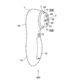
- FIG. 12 is an external view of the contact-type internal thermometer 400 according to the present embodiment as viewed from the measurement surface side.
- the contact-type internal thermometer 400 according to the present embodiment has four probes on the measurement surface 20, that is, a first probe 30, a second probe 31, a third probe 32, and a fourth probe.
- the probe 35 is provided.
- the arrangement of these probes is arbitrary, but in the embodiment shown here, each probe is arranged so as to be positioned at the apex of a square.
- FIG. 13 is an enlarged cross-sectional view of the vicinity of the measuring head 2 taken along line XIII-XIII in FIG.
- the bypass member 42 is divided into two parts, a first bypass member 44 and a second bypass member 45.
- the first bypass member 44 and the second bypass member 45 are independently attached to the pressing rod 40 via the heat insulating material 41, and both are thermally isolated.
- the 1st bypass member 44 contacts the 3rd probe 32 and the 1st back side temperature sensor 33b, and is thermally couple
- the measurement object and the first back surface temperature sensor 33b are thermally connected.
- the second bypass member 45 is in contact with and thermally coupled to the fourth probe 35 and the second back surface temperature sensor 34b by pressing down the push button 4 (see FIG. 1).
- the measurement object and the second back side temperature sensor 34b are thermally connected.
- first probe 30, the second probe 31, the third probe 32, and the fourth probe 35 are supported so as not to contact each other by the measurement head 2 made of a material having low thermal conductivity, They are thermally isolated from each other. For these reasons, the bypass flow path connected by the first bypass member 44 and the bypass flow path connected by the second bypass member 45 are thermally independent from each other.
- the first back surface temperature sensor 33b and the second back surface temperature sensor 34b are not thermally connected, and the first back surface temperature sensor 33b and the second back surface temperature sensor are not thermally connected. Interference due to heat exchange between 34b does not occur.
- the bypass member 42 shown in the present embodiment is divided into two members, and the structure for thermally separating the first back surface temperature sensor 33b and the second back surface temperature sensor 34b is as in this embodiment. Furthermore, this may be applied not only to the first embodiment but also to the second and third embodiments.
Landscapes
- Physics & Mathematics (AREA)
- General Physics & Mathematics (AREA)
- Measuring Temperature Or Quantity Of Heat (AREA)
- Measuring And Recording Apparatus For Diagnosis (AREA)
Abstract
迅速・正確かつ簡便に測定対象物の内部温度を測定可能な接触式内部温度計を提供すること。本発明に係る接触式内部温度計100は、測定面20と、熱抵抗体の測定面側に測定面側温度センサが配置され、背面側に背面側温度センサが配置される第1の温度センサ積層体33と第2の温度センサ積層体34を少なくとも有し、測定対象物と第1の温度センサ積層体33の背面側温度センサ及び第2の温度センサ積層体34の背面側温度センサ間の熱的接続であるバイパス流路を形成するバイパス部材42と、前記バイパス流路を接続及び遮断するバイパス流路接続遮断機構と、前記測定面側温度センサ及び前記背面側温度センサの測定結果に基づいて測定対象物の内部温度を算出する内部温度算出部と、を有する。
Description
本発明は、接触式内部温度計に関する。
様々な状況において、測定対象物の表面温度ではなく、その内部温度を迅速・正確かつ簡便(すなわち、非侵襲)に測定したいとの要求が存在している。そのような要求の代表的なものとして、人体を含む生体の体温測定が挙げられる。しかしながら、生体の内部温度(深部体温などと称されることもある)、すなわち、血流により概ね恒温に保たれていると考えられる程度の生体内部の温度を測定するのは通常困難である。測定対象が人体の場合、一般的には、舌下や脇の下など熱が外部に逃げにくい場所に温度計を保持し、温度計と人体とが熱平衡状態となってからの温度計の読みを体温として採用することが多いが、熱平衡状態が得られるまでに5分から10分程度と長時間を要し、また得られる体温は必ずしもその内部温度と一致するとは限らない。このため、かかる方式は、乳幼児やある種の傷病患者等、長時間の体温測定が困難な対象への適用が困難な場合があり、また、精密な体温管理を行うに足る精度の高い体温を得るのは難しい。
そのため、人体の内部温度を迅速・正確に測定するための種々の温度計が提案されている。
特許文献1には、断熱材を挟む第1の温度測定手段と第2の温度測定手段、及び第1の温度測定手段を加熱する可変温度加熱手段を有する電子体温計が記載されている。この電子体温計は、第2の温度測定手段で被測定体側の部位の温度を測定しつつ第1の温度測定手段での温度も測定する。そして可変温度加熱手段で第1の温度測定手段の温度を変化させることで熱平衡状態となることを防ぎながら複数回の測定を行い、得られた結果に基づいて熱伝導方程式の逆問題を解くことで内部温度を算出する。
特許文献2には、体表面に接触する第1の温度センサと、第1の温度センサに対し断熱材を挟んで配置される第2の温度センサからなる組を少なくとも二組備え、それぞれの組における断熱材の熱抵抗値が異なる非加熱型深部体温計が記載されている。この非加熱型深部体温計は、定常状態における各温度センサにおける温度測定結果から連立熱伝導方程式を解き、深部体温を求める。
上述の特許文献1のように、接触式内部温度計が可変温度加熱手段、すなわちヒータを必要とする場合には、消費電力が大きく、小型であることが要求される携帯型の接触式内部温度計には不向きである。また、温度計を人体表面と接触させることを考慮すると、ヒータを搭載するのは好ましくない。
上述の特許文献2ではヒータを必要としないが、定常状態での測定が必要であり、体表面からは断熱材を隔てて配置される第2の温度センサが定常状態となるまでには相当程度の時間が必要であり、迅速な内部温度測定が実現されているとは言い難い。
本発明はかかる事情に鑑みてなされたものであり、その解決しようとする課題は、迅速・正確かつ簡便に測定対象物の内部温度を測定可能な接触式内部温度計を提供することである。
なお、ここまでの記載は接触式内部温度計の代表的な例として人体の内部温度を測定する体温計について主に説明したが、本発明が対象とする接触式内部温度計はこれに限定されるものでなく、生物・無生物問わず非侵襲にてその内部温度を測定する必要があるいかなる測定対象物にも適用可能である。
上記課題を解決すべく本出願において開示される発明は種々の側面を有しており、それら側面の代表的なものの概要は以下のとおりである。
(1)測定対象物の内部温度を算出するため前記測定対象物の被測定面に接触させる測定面と、第1の熱抵抗体の測定面側に第1の測定面側温度センサが配置され、背面側に第1の背面側温度センサが配置される第1の温度センサ積層体と、第2の熱抵抗体の測定面側に第2の測定面側温度センサが配置され、背面側に第2の背面側温度センサが配置される第2の温度センサ積層体を少なくとも有し、定常状態において前記第1の温度センサ積層体を通過する熱流束と前記第2の温度センサを通過する熱流束が異なるように構成され、前記測定対象物と前記第1の背面側温度センサ間及び、前記測定対象物と前記第2の背面側温度センサ間の熱的接続であるバイパス流路を形成するバイパス部材と、前記バイパス流路を接続及び遮断するバイパス流路接続遮断機構と、前記第1の測定面側温度センサ、前記第1の背面側温度センサ、前記第2の測定面側温度センサ及び前記第2の背面側温度センサの測定結果に基づいて前記測定対象物の内部温度を算出する内部温度算出部と、を有する接触式内部温度計。
(2)(1)において、前記バイパス部材の熱抵抗は、前記第1の熱抵抗体及び前記第2の熱抵抗体の熱抵抗より小さい接触式内部温度計。
(3)(1)又は(2)において、前記バイパス流路が接続されているか否かを検知する接続検知部を有し、前記内部温度算出部は、前記接続検知部により前記バイパス流路が接続されたことを検知した後、さらに前記第1の温度センサ積層体及び前記第2の温度センサ積層体が定常状態に達した後に前記測定対象物の内部温度を算出する接触式内部温度計。
(4)(3)において、前記接続検知部により前記バイパス流路が接続されたことを検知した後、前記バイパス流路を遮断すべきタイミングを検知する遮断タイミング検知部と、前記遮断タイミング検知部により前記バイパス流路を遮断すべきタイミングが検知されたことを使用者に通知する遮断タイミング通知部と、を有する接触式内部温度計。
(5)(3)において、前記接続検知部により前記バイパス流路が接続されたことを検知した後、前記バイパス流路を遮断すべきタイミングを検知する遮断タイミング検知部と、前記遮断タイミング検知部により前記バイパス流路を遮断すべきタイミングが検知された際に前記バイパス流路を遮断する遮断部と、を有する接触式内部温度計。
(6)(4)又は(5)において、前記内部温度算出部は、前記接続検知部により前記バイパス流路が遮断されたことを検知した後、さらに前記第1の温度センサ積層体及び前記第2の温度センサ積層体が定常状態に達した後に前記測定対象物の内部温度を算出する接触式内部温度計。
(7)(3)において、前記バイパス部材は、前記バイパス部材の温度上昇に応じて前記バイパス流路を遮断する温度感応性遮断機構を含む接触式内部温度計。
(8)(1)乃至(7)のいずれかにおいて、前記バイパス流路接続遮断機構は、使用者が操作する押ボタンを含み、使用者が前記押ボタンを押すことにより前記バイパス流路が接続されるか、又は、前記測定面をケースに対し移動可能に支持する弾性支持構造を含み、使用者が前記測定面を前記測定対象物に押し付けることにより前記バイパス流路が接続される接触式内部温度計。
(9)(1)乃至(8)のいずれかにおいて、前記測定面に設けられ、前記第1の測定面側温度センサと熱的に結合する第1のプローブと、前記測定面に設けられ、前記第2の測定面側温度センサと熱的に結合する第2のプローブと、前記測定面に設けられ、前記バイパス部材と熱的に結合する第3のプローブと、を有し、前記第1のプローブ、前記第2のプローブ及び前記第3のプローブは互いに熱的に隔離される接触式内部温度計。
(10)(1)乃至(8)のいずれかにおいて、前記バイパス部材は、前記測定対象物と前記第1の背面側温度センサ間を熱的に接続する第1のバイパス部材と、前記測定対象物と前記第2の背面側温度センサ間を熱的に接続するとともに前記第1のバイパス部材から熱的に隔離された第2のバイパス部材を有し、前記測定面に設けられ、前記第1の測定面側温度センサと熱的に結合する第1のプローブと、前記測定面に設けられ、前記第2の測定面側温度センサと熱的に結合する第2のプローブと、前記測定面に設けられ、前記第1のバイパス部材と熱的に結合する第3のプローブと、前記測定面に設けられ、前記第2のバイパス部材と熱的に結合する第4のプローブと、を有し、前記第1のプローブ、前記第2のプローブ、前記第3のプローブ及び前記第4のプローブは互いに熱的に隔離される接触式内部温度計。
(11)(1)乃至(10)のいずれかにおいて、前記内部温度算出部による内部温度の算出後、前記第1の温度センサ積層体、前記第2の温度センサ積層体及び前記バイパス部材の少なくともいずれかを冷却する冷却機構を有する接触式内部温度計。
上記(1)の側面によれば、迅速・正確かつ簡便に測定対象物の内部温度を測定可能な接触式内部温度計が提供される。
上記(2)の側面によれば、第1の温度センサ積層体及び第2の温度センサ積層体は速やかに定常状態に達する。
上記(3)の側面によれば、正確に測定対象物の内部温度を算出できる。
上記(4)の側面によれば、使用者はバイパス流路を適正なタイミングで遮断できる。
上記(5)の側面によれば、使用者によるバイパス流路の遮断操作を必要とせずに、バイパス流路を適正なタイミングで遮断できる。
上記(6)の側面によれば、正確に測定対象物の内部温度を算出できる。
上記(7)の側面によれば、使用者によるバイパス流路の遮断操作や、バイパス流路を遮断するための制御を行うことなく、自律的にバイパス流路を遮断できる。
上記(8)の側面によれば、使用者は簡単な操作でバイパス流路を接続できる。
上記(9)の側面によれば、第1の温度センサ積層体と第2の温度センサ積層体間での熱流に起因する測定誤差を低減できる。
上記(10)の側面によれば、第1の温度センサ積層体と第2の温度センサ積層体間での熱流に起因する測定誤差を大幅に低減できる。
上記(11)の側面によれば、連続して測定を行う際にもそれぞれ正確に測定対象物の内部温度を測定できる。
以下、本発明の第1の実施形態について図面に基づき詳細に説明する。
図1は、本発明の第1の実施形態に係る接触式内部温度計100を背面側から見た外観図、図2は同実施形態に係る接触式内部温度計100を測定面側から見た外観図である。なお、本明細書にて接触式内部温度計とは、温度計であって、測定対象表面に接触させることにより内部温度を測定する温度計を意味している。また、内部温度とは、測定対象の表面温度でなく、その内部であって、実質的に恒温熱源と考えられる部位の温度を意味している。ここで、実質的に恒温熱源と考えられるとは、測定対象内部の熱容量が大きい場合や、測定対象内部に常に熱が供給される結果、接触式内部温度計による測定がその温度に実用上の影響を及ぼさないと考えられることを意味している。たとえば、測定対象が生体である場合には、血流により体幹より常に熱が供給されることとなるので、後者に該当する。
本実施形態で示す接触式内部温度計100は、図示の通り携帯式であり、ケース1の先端に測定ヘッド2が取り付けられている。測定ヘッド2はケース1から突き出すように設けられており、その先端はおおむね平坦な測定面20となっている。そして、かかる測定面20を測定対象物の被測定面、例えば皮膚に接触させることによりその内部温度を計測する。測定面20の表面には、略円形の第1のプローブ30、第2のプローブ31及び第3のプローブ32が図2に示すように、接触式内部温度計100の長手方向に沿って直列に配置されている。なお、これら第1のプローブ30、第2のプローブ31及び第3のプローブ32の配置は任意であり、その配置方向は必ずしも接触式内部温度計100の長手方向に沿ったものでなくともよく、さらには、各プローブを正三角形の頂点となる位置に配置する等直列に配置せずともよい。
ケース1の測定面20の反対側の面である背面10には、ランプ11、押ボタン4、表示部12、ブザー13が設けられている。以降、本明細書では、測定面20が向く方向を測定面側、その反対方向である背面が向く方向を背面側と称する。また、ケース1は長く伸び丸みを帯びた形状をしており、使用者が手に持つグリップ14を形成している。図2に見られるように、ケース1のグリップ14の測定面側には電池蓋15が設けられ、内部に接触式内部温度計100の電源となる電池を収容するようになっている。また、ケース1の適宜の位置、ここでは図2に示した位置に吸気穴16が、測定ヘッド2の側面に排気穴21が設けられ、それぞれの内部空間が外気と連通するようになされている。ケース1と測定ヘッド2は、支持環5により接続されている。
なお、図1及び図2に示した接触式内部温度計100のデザインは一例である。かかるデザインは、その主たる用途や市場性等を考慮の上適宜変更して差し支えない。また、各構成部品の配置は、その機能を損なわない範囲で任意に選択してよい。
図3は、図1のIII-III線による接触式内部温度計100の概略断面図である。ケース1は、好ましくはABS樹脂等任意の合成樹脂製の中空の成形品であり、接触式内部温度計100を構成する各種部品をその内部に一体に収容する。グリップ14内には、電池6及び回路基板17が収容されている。回路基板17上には、その上に図示しないコントローラをはじめとする各種の電子部品が実装されており、電池6からの電力供給を受けて、電力を必要とする全ての部品への電力を供給するとともにその動作を制御している。電池6は、図示のものは市販の単4型(米国ではAAAと称される)乾電池であるが、その形式は任意のものであってよく、ボタン型、角型等の形状や、1次電池・2次電池の別も任意であってよい。なお、各部品と回路基板17とを電気的に接続する配線は、図示が煩雑となるため省略している。
ランプ11は、好ましくは多色発光可能な発光ダイオードであり、接触式内部温度計100の状態を使用者に通知するために点灯するものである。表示部12は、本実施形態では液晶表示装置であり、接触式内部温度計100の測定結果を図1に示すような態様で使用者に通知するためのものである。もちろん、表示部12にはこのほかにも任意の情報、例えば、電池6の残量等を表示するようにしてよい。あるいは、接触式内部温度計100の状態を併せて表示するようにして、ランプ11を省略してもよい。ブザー13は、本実施形態では一般的な電子ブザーであり、ビープ音により接触式内部温度計100の状態を使用者に通知するためのものである。なお、ブザー13の形式も又任意であり、スピーカを備えるようにして、音声あるいはメロディ等による通知をするようにしてもよい。あるいは、ランプ11及び/又は表示部12による通知のみとして、ブザー13を省略してもよい。
また、ケース1内部には隔壁18が設けられており、ケース1内部をグリップ空間19aとヘッド空間19bとに仕切っている。隔壁18には開口が設けられており、かかる開口を塞ぐようにブロア7が取り付けられている。ブロア7の機能については後述する。
ケース1の先端部には、支持環5を介して測定ヘッド2が取り付けられる。支持環5は、好ましくはシリコンゴム或いはその発泡体等の弾力を有し且つ断熱性に優れた材料で形成され、測定ヘッド2のケース1に対する若干の動きを許容するとともに、測定ヘッド2からケース1への伝熱を遮断するようになっている。これは、測定面20を測定対象物に接触させる際に、測定面20が確実に測定対象物に密着するようにするためと、測定ヘッド2からケース1へと熱が流出することによる測定誤差の発生を防止するためである。しかしながら、支持環5は必須の構成でなく、測定面20と測定対象物との密着に問題がなく、また測定ヘッド2が十分に熱伝導率の低い材質であり実用上問題ない場合には、これを省略し、測定ヘッド2を直接ケース1に固定する又は両者を一体に形成するなどしてもよい。また、支持環5の形状も環状に限定されるものでなく、任意の形状のものを用いてよい。
測定ヘッド2は、形状が安定しており、熱伝導率が低く、かつ比熱の小さい材質で形成することが好ましく、例えば、硬質発泡ウレタンや硬質発泡塩化ビニルが好適に用いられる。しかしながら、この点についても実用上の問題がなければ材質は特に限定されるものでなく、任意でよい。
測定ヘッド2の測定面20には第1のプローブ30、第2のプローブ31及び第3のプローブ32に対応する位置にそれぞれ開口が設けられており、各プローブが測定面20からわずかに突出するように取り付けられている。各プローブは、熱伝導率の高い材質であることが好ましく、本実施形態では金属製である。なお、各プローブの材質は耐腐食性を備えていることが好ましく、金属材料では、アルミニウムやステンレスが好適である。なお、上述の通り、測定ヘッド2自体は熱伝導率が低い材質から構成されるため、第1のプローブ30、第2のプローブ31及び第3のプローブ32は、互いに熱的に隔離されることとなる。
第1のプローブ30の背面側には、第1の温度センサ積層体33が設けられており、両者は互いに熱的に結合している。また、第2のプローブ31の背面側には、第2の温度センサ積層体34が設けられており、両者は互いに熱的に結合している。第1の温度センサ積層体33及び第2の温度センサ積層体34の詳細については後述する。なお、温度センサ積層体は、本実施形態では第1の温度センサ積層体33及び第2の温度センサ積層体34の2つを設けているが、誤差の分散あるいは故障時のバックアップ目的で、温度センサ積層体を3つ以上設けるようにしてもよい。
押ボタン4は、ケース1の背面10に測定面側に押下できるように配置される。本実施形態では、ケース1に設けられたバネ受座19上に設けられたバネ8により背面側に付勢されるようになっている。しかしながら、押ボタン4を支持及び付勢する構造はここで示したものに限定されるものではなく、後述するバイパス部材42を測定面側に押し付けることが可能な構造であればどのようなものであってもよい。押ボタン4からは測定面側に向かって押付桿40が伸びており、その先端に断熱材41を介して、バイパス部材42が取り付けられている。バイパス部材42は熱伝導率の高い材質であることが好ましく、本実施形態では金属製である。また、押ボタン4を押し下げたときにバイパス部材42が第1の温度センサ積層体33、第2の温度センサ積層体34及び第3のプローブ32のそれぞれの背面側表面に接触する形状となっている。押付桿40の断面形状は特に限定されず、中実又は中空の円柱又は角柱、十字形状等任意のものとしてよい。
図4は、図3における測定ヘッド2近傍の拡大断面図である。ここでは、図3の支持環5及び断熱材41並びにそれら部材より背面側に位置する部材は図示を省略している。
同図に詳細に示されるように、第1の温度センサ積層体33は、測定面側に配置され、第1のプローブ30と接触し熱的に結合する第1の測定面側温度センサ33aと、背面側に配置される第1の背面側温度センサ33bと、その間に配置され、第1の測定面側温度センサ33aから第1の背面側温度センサ33bへの熱流路を形成する第1の熱抵抗体33cを積層した構造となっている。また、第2の温度センサ積層体34も第1の温度センサ積層体33と同様の構造となっており、測定面側に配置され、第2のプローブ31に接触し熱的に結合する第2の測定面側温度センサ34a、背面側に配置される第2の背面側温度センサ34bと、その間に配置され、第2の測定面側温度センサ34aから第2の背面側温度センサ34bへの熱流路を形成する第2の熱抵抗体34cを積層した構造となっている。従って、測定面20を測定対象物に接触させると、測定対象物から熱がプローブ30及びプローブ31に伝わり、その熱はそれぞれ第1の温度センサ積層体33については第1の測定面側温度センサ33a、第1の熱抵抗体33c、第1の背面側温度センサ33bを順番に通過し、第2の温度センサ積層体34については第2の測定面側温度センサ34a、第2の熱抵抗体34c、第2の背面側温度センサ34bを順番に通過して大気に放散されることになる。
各温度センサにはどのようなものを用いてもよいが、本実施形態ではサーミスタである。それぞれの温度センサは、回路基板17(図3参照)に図示しない配線により接続されており、各温度センサにおける温度を検知できるようになっている。
ここで重要なのは、定常状態において、第1の温度センサ積層体33を通過する熱流束と、第2の温度センサ積層体34を通過する熱流束が異なっており、なおかつ、少なくともその熱抵抗の比が既知であることである。すなわち、第1の温度センサ積層体33と第2の温度センサ積層体34は、それぞれの両端に等しい温度差が与えられた場合に、それぞれの温度センサ積層体を通過する熱流束が互いに異なるように構成される。このように第1の温度センサ積層体33と第2の温度センサ積層体34を通過する熱流束を異ならしめる方法は様々なものがあり、本実施形態で採用しているように、第1の熱抵抗体33cと第2の熱抵抗体34cの熱抵抗を異なるものとしたり、あるいは、一方あるいは両方の温度センサ積層体の背面に板状あるいはその他の形状の放熱制御部材を配置したりすることにより実現される。後者の場合には、第1の熱抵抗体33cと第2の熱抵抗体34cの熱抵抗が等しくてもよく、その熱抵抗の比は1:1である。本実施形態のように、第1の熱抵抗体33cと第2の熱抵抗体34cの熱抵抗を異なるものとする場合、それぞれの熱抵抗は、その材質の選択や、形状の制御により任意のものに設定できる。熱抵抗を設定する手法の一例として、本実施形態では、第1の熱抵抗体33c及び第2の熱抵抗体34cを同材質かつ断面積の等しい円柱形状としており、その高さのみを異ならしめている。このように第1の熱抵抗体33cと第2の熱抵抗体34cの材質及び断面積を等しいものとすると、その熱抵抗の値はその高さに比例するため、熱抵抗の比を容易に任意のものに設定できる。本実施形態では、その高さ及び熱抵抗の比は1:2となっている。もちろん、この比は異なるものとしてもよい。
バイパス部材42は、測定面側に向かって突き出す柱状部42a,42b,42cを有しており、柱状部42aと42bの間を梁42dにより、柱状部42aと42cの間を梁42eにより接続した形状となっている。そして、押ボタン4(図3参照)を押し下げたときに、柱状部42aの測定面側表面が第3のプローブ32の背面側表面に接触し、また柱状部42b及び柱状部42cの測定面側表面がそれぞれ第1の温度センサ積層体33の第1の背面側温度センサ33b及び第2の温度センサ積層体34の第2の背面側温度センサ34bに接触し、プローブ32と第1の背面側温度センサ33b及び第2の背面側温度センサ34bとが熱的に接続される。このとき、測定面20が測定対象物に接触しているならば、バイパス部材42は、測定対象物と第1の背面側温度センサ33b間及び、測定対象物と第2の背面側温度センサ34b間の熱的接続であるバイパス流路を形成することになる。もちろん、このバイパス流路は、押ボタン4(図3参照)の押し下げを取りやめた場合には、バイパス部材42が第3のプローブ32、第1の背面側温度センサ33b及び第2の背面側温度センサ34bから離れることとなるため、遮断される。
なお、梁42d及び42eは、若干の弾性変形を許容することが好ましい。これにより、バイパス部材42の幾何学的形状や、第3のプローブ32、第1の背面側温度センサ33b及び第2の背面側温度センサ34bの配置位置に若干の寸法誤差があっても、バイパス部材42と各部材との接触による熱的結合を確実なものにできる。
ここで、本実施形態の接触式内部温度計100による内部温度の測定原理を、図5を用いて説明する。
図5は、本実施形態に係る接触式内部温度計100の測定ヘッド2に設けられた測定部の等価熱回路を示す図である。同図を図4を参照しつつ説明すると、Tbは測定対象である内部温度、T11は第1の測定面側温度センサ33aにおける温度、T12は第1の背面側温度センサ33bにおける温度、T21は第2の測定面側温度センサ34aにおける温度、T22は第1の背面側温度センサ34bにおける温度である。また、熱抵抗Rbは測定対象内部から第1のプローブ30及び第2のプローブ31を通して第1の測定面側温度センサ33a及び第2の測定面側温度センサ34aに熱が伝わる際の熱抵抗であり、熱抵抗R1は第1の熱抵抗体33cの、熱抵抗R2は第2の熱抵抗体34cの熱抵抗である。そして、Tb>T11>T12及び、Tb>T12>T22が成立している。
ここで、図に示した系が定常状態にあると仮定すると、TbよりT12へと流れる熱流束は一定であるから、次式が成立する。
[式1]
 又同様に、TbよりT22へと流れる熱流束を考えると、
[式2]
 が成立する。この式1及び式2より、内部温度Tbは、
[式3]
 として求められる。なお、ここでK=R1/R2であり、本実施形態の例ではK=1/2である。先述したように、第1の熱抵抗体33cと第2の熱抵抗体34cの熱抵抗が等しい場合にはR1=R2であるから、K=1となる。
[式1]
[式2]
[式3]
ところで、式3により内部温度Tbを求めるためには、図5に示した系が定常状態とならなければならない。しかしながら、図4より理解できるように、特に第1の背面側温度センサ33b及び第2の背面側温度センサ34bは、それぞれ第1の熱抵抗体33c及び第2の熱抵抗体34cを介して測定対象物と熱的に接合されることとなるから、測定対象物からの熱が伝わりにくく、その温度が上昇して定常状態に達するまでに相当の時間を要する。そこで、本実施形態では、図5に示した系が定常状態に達する時間を短縮するため、バイパス部材42によるバイパス流路を形成することにより、第3のプローブ32から熱伝導率が高く、熱抵抗の小さいバイパス部材42を通じて被接触面の熱を第1の背面側温度センサ33b及び第2の背面側温度センサ34bに伝え、その温度を速やかに上昇させるのである。その後バイパス部材42を引き上げ、バイパス流路を遮断すれば、第1の背面側温度センサ33b及び第2の背面側温度センサ34bは概ね定常状態に近い温度まで加熱されているため、速やかに定常状態へと移行する。これにより、本実施形態に係る接触式内部温度計100は、迅速に内部温度の測定を可能としている。従って、バイパス部材42の熱抵抗は、少なくとも第1の熱抵抗体33c及び第2の熱抵抗体34cの熱抵抗より小さくなければならない。
続いて、本実施形態に係る接触式内部温度計100を用いて内部温度を測定する手順、すなわち測温動作の手順を図1乃至4を参照しつつ説明する。手順1:接触式内部温度計100の測定面20を測定対象物に接触させる。手順2:押ボタン4を押し下げる。これにより、バイパス部材42が第1の温度センサ積層体33、第2の温度センサ積層体34及び第3のプローブのそれぞれの背面側表面に接触し、バイパス流路が接続される。また、回路基板17に搭載されたコントローラはバイパス流路が形成されたことを検知して測温動作を開始する。このとき、本実施形態では、コントローラはブザー13によるビープ音により測定を開始したことを使用者に通知する。同時に、ランプ11を任意の色、例えば赤色に点灯し、使用者に測定面20を測定対象物に接触させつつ押ボタン4を押し下げた状態を維持するよう促す。
なお、バイパス流路が接続されたことを検知するため、接触式内部温度計100にはバイパス流路が接続されているか否かを検知する接続検知部が設けられる。この接続検知部の構造は、種々のものが考えられる。例えば、ボタン4、押付桿40或いはバネ8の任意の位置に電気的スイッチを設け、ボタン4が押し下げられていることを検知してよい。あるいは、バイパス部材42と第3のプローブ32、第1の温度センサ積層体33の背面側表面、第2の温度センサ積層体34の背面側表面のいずれか若しくは複数を電気的接点として用い、これら部材が接触したことを電気的に検出するようにしてもよい。本実施形態では、バイパス部材42と第3のプローブ32を接点として用い、両者の接触を電気的に検出するようにしている。かかる方法は、スイッチを設ける方法に比べ、機械的誤差による誤検出の恐れがない点で優れている。手順3:コントローラは、バイパス流路を遮断すべきタイミングを検知し、バイパス流路を遮断すべきタイミングが検知されたことを使用者に通知する。この動作は、第1の背面側温度センサ33b及び第2の背面側温度センサ34bが十分に、すなわち、定常状態に近い状態まで昇温されたことを使用者に通知して、ボタン4の押し下げを取りやめる(すなわち、ボタン4に加えていた力を緩める、又はボタンから指を離す)よう促す動作である。これにより、ボタン4がバネ8により当初の位置に復帰し、バイパス流路が遮断される。
なお、バイパス流路を遮断すべきタイミングを検知するため、接触式内部温度計100には遮断タイミング検知部が設けられる。この遮断タイミング検知部構造はいかなるものであってもよく、専用の回路あるいは機構を備えるようにしてもよいが、本実施形態では、回路基板17上に設けられたコントローラが実行するソフトウェアにより遮断タイミング検知部が仮想的に実現されている。すなわち、回路基板17上に設けられたコントローラは遮断タイミング検知部を兼ねるものである。
バイパス流路を遮断すべきタイミングの判断にあたって用いる基準は、上述の通り、第1の背面側温度センサ33b及び第2の背面側温度センサ34bが定常状態に近い温度まで昇温されたと合理的に算出されるタイミングを検出できるものであればいかなる基準を用いてもよい。そのような基準を例示すると、次のとおりである。基準1:第1の背面側温度センサ33b及び/又は第2の背面側温度センサ34bの温度変化があらかじめ定められた閾値以下となる。
この基準1は、第1の背面側温度センサ33b及び/又は第2の背面側温度センサ34bがバイパス流路が接続された状態で略定常状態となったことを検出するものである。この状態では、第1の背面側温度センサ33b及び/又は第2の背面側温度センサ34bの温度は測定対象物の表面温度から流入した熱により十分昇温されていると考えられる。なお、第1の背面側温度センサ33b及び第2の背面側温度センサ34bの両者についての温度変化があらかじめ定められた閾値以下となることを検出することが好ましいが、いずれか片方のみについて検出するようにしてもよい。基準2:第1の背面側温度センサ33b及び/又は第2の背面側温度センサ34bの温度があらかじめ定められた閾値以上となる。
この基準2は、接触式内部温度計100により測定しようとする対象の温度の範囲が概ね分かっている場合に採用できる。例えば、接触式内部温度計100が人体を対象とする体温計である場合には、その表面温度はおおむね摂氏35度以上となり、それ以下となることは通常ない。このような場合には、閾値として、例えば、摂氏33度を設定することにより、第1の背面側温度センサ33b及び/又は第2の背面側温度センサ34bが定常状態に近い温度まで昇温されたことを検出できる。この検出は、第1の背面側温度センサ33b及び第2の背面側温度センサ34bの両者について行ってもよいし、いずれか片方のみでもよい。基準3:バイパス流路が接続されている時間があらかじめ定められた時間以上となる。
この基準3は、バイパス部材42、第1の背面側温度センサ33b及び第2の背面側温度センサ34bの熱容量が既知であり、またバイパス部材42の伝熱速度もおおよそ予測できることから、想定される用途によってあらかじめ定めた時間バイパス流路が接続されているならば、当然に第1の背面側温度センサ33b及び第2の背面側温度センサ34bの温度が定常状態に近い温度まで昇温していると算出するものである。この時間は、理論的にあるいは実験的にあらかじめ求めておくとよい。
以上の基準は、これらのうちいずれかを用いてもよいし、複数を組み合わせて用いてもよい。本実施形態に係る接触式内部温度計100では、基準1を用いている。もちろん、ここにあげた基準1乃至3以外の基準を用いてもよい。
かかる基準に基づいてバイパス流路を遮断すべきタイミングが検知されたならば、コントローラは、ブザー13によるビープ音によりバイパス流路を遮断すべきタイミングが到来したことを使用者に通知すると同時に、ランプ11を先ほどの色とは異なる任意の色、例えば黄色に点灯し、使用者には、内部温度の測定が進行中であり、測定面20を測定対象物に接触させたまま押ボタン4を離した状態に保持するよう促す。従って、ブザー13とランプ11は、使用者にバイパス流路を遮断すべきタイミングを通知する遮断タイミング通知部として機能することになる。手順4:コントローラは、バイパス流路が遮断された後、第1の温度センサ積層体33及び前記第2の温度センサ積層体34が定常状態に達した後に測定対象物の内部温度を算出し、表示する。すなわち、コントローラは、第1の測定面側温度センサ33a、第1の背面側温度センサ33b、第2の測定面側温度センサ34a及び第2の背面側温度センサ34bの出力を監視し、これら温度センサの温度変化があらかじめ定められた閾値以下となったことを検出すると、これら温度センサからの出力を用いて、上述の式3から内部温度を求める。従って、コントローラは、第1の測定面側温度センサ33a、第1の背面側温度センサ33b、第2の測定面側温度センサ34a及び第2の背面側温度センサ34bの測定結果に基づいて測定対象物の内部温度を算出する内部温度算出部として機能する。さらに、コントローラにより実現される内部温度算出部は、接続検知部によりバイパス流路が接続され、さらにバイパス流路が遮断されたことを検知した後、第1の温度センサ積層体33及び前記第2の温度センサ積層体34が定常状態に達した後に測定対象物の内部温度を算出するものである。
コントローラは、このようにして算出された内部温度を図1に示したように表示部12に表示する。また、ブザー13によるビープ音の発生、並びに、ランプ11を先ほどの色とは異なる任意の色、例えば緑色に点灯することにより、使用者に測定が終了したことを通知する。なお、算出された内部温度は、本実施形態では表示部12に表示することにより使用者に通知することとしているが、これに限られず、接触式内部温度計100に設けたメモリに蓄積したり、接触式内部温度計100の外部の機器に有線又は無線にて出力したりしてもよい。この場合には、表示部12は必ずしも必須の構成ではない。
以上の手順を使用者の視点から再度説明すれば、まず、接触式内部温度計100の測定面20を測定対象物に接触させ、ボタン4を押し下げることにより測定が開始される。このとき、ビープ音が鳴り、ランプ11が赤色に点灯する。続いて、再度ビープ音が鳴り、ランプ11が黄色に点灯するので、ボタン4から指を離し、引き続き測定面20を測定対象物に接触させておく。最後に三度ビープ音が鳴り、ランプ11が緑色に点灯すれば測定終了であり、接触式内部温度計100を測定対象物から離し、表示部12に表示された測定結果を確認する。この間要する時間は、測定対象及び接触式内部温度計100の各部の大きさ(熱容量)にも依存するが、人体の内部温度を測定対象とする場合には、概ね10秒程度である。
なお、以上の説明では、使用者への測定開始の通知、バイパス流路遮断タイミングの通知、測定終了の各種通知をいずれもブザー13によるビープ音及びランプ11の点灯により行ったが、これらの通知の方法はここで例示したものに限定されない。特に、ビープ音についてはこれを省略したり、或いは使用者の設定によりこれを発声しないこととしてもよい。音声を用いず、ランプ11の点灯のみにより使用者に各種の通知を行うようにすると、例えば測定対象が就寝中の乳児である場合に、乳児の睡眠を妨げることなく測定が可能である等好ましい場合がある。もちろん、ランプ11の点灯をどのようにするか、例えば発光色をどのように選択するかは任意である。また、発色光によらず、ランプ11を点滅させたり、発光光の強度を変化させたり、あるいはランプ11を複数設けておき、その点灯数を違えることにより使用者に各種通知を行うようにしてもよい。さらに前述したように、ランプ11でなく、表示部12により使用者に各種通知を行ってもよい。手順5:コントローラは、ブロア7を作動させ、測定部を冷却する。
この動作は、第1の温度センサ積層体33、第2の温度センサ積層体34及びバイパス部材42を冷却し、次の測定に備えるものである。例えば、最初に比較的高温の測定対象の内部温度を測定し、その直後に、比較的低温の測定対象の内部温度を続けて測定する場合を考えると、最初の測定時に、第1の温度センサ積層体33、第2の温度センサ積層体34及びバイパス部材42が次の測定時に必要とされる以上に高温となる場合があり得る。このとき、第1の温度センサ積層体33及び第2の温度センサ積層体34、場合によってはバイパス部材42が定常状態となるためには、これら部材の放熱による自然冷却を待たなければならず、測定に時間を要する場合があり得る。そのため、測定の度に第1の温度センサ積層体33、第2の温度センサ積層体34及びバイパス部材42をある程度冷却するのである。
本実施形態では、ブロア7は図1のグリップ空間19aからヘッド空間19bへと流れる気流を発生させる。そのため、ブロア7により誘起される空気の流れは、図中矢印に示すように、吸気穴16から吸い込まれ、ブロア7を通過し、第1の温度センサ積層体33、第2の温度センサ積層体34及びバイパス部材42の近傍を通過して排気穴21から排出されるものとなる。従って、本実施形態のブロア7、吸気穴16及び排気穴21は協働して第1の温度センサ積層体33、第2の温度センサ積層体34及びバイパス部材42を冷却する冷却機構を構成することになる。
なお、冷却機構の構成はどのようなものであってもよく、ブロア7、吸気穴16及び排気穴21の配置は任意である。また、吸排気の向きを逆にしてもよい。さらに、冷却対象は、第1の温度センサ積層体33、第2の温度センサ積層体34及びバイパス部材42の少なくともいずれかであればよい。また、ブロア7の形式は特に限定されず、一般的なファンであってもよいし、圧電素子を利用したマイクロブロアであってもよい。あるいは、連続して測定する際の測定時間に実用上の問題がなければ、この冷却機構そのものを省略しても差し支えない。
図6は、本実施形態に係る接触式内部温度計100の測温動作における、第1の背面側温度センサ33b及び第2の背面側温度センサ34bの温度変化を示すグラフである。グラフ中横軸は測温を開始してからの時間t、縦軸は各温度センサの温度Tを示す。また、グラフ中太実線で示した曲線Aは、第1の背面側温度センサ33bの温度変化を、太破線で示した曲線Bは、第2の背面側温度センサ34bの温度変化を示している。なお、グラフ中細実線で示した曲線C及び細破線で示した曲線Dは、バイパス部材42を用いない場合の第1の背面側温度センサ33b及び2の背面側温度センサ34bの温度変化を比較のために示したものである。
同図に示すように、時刻t=0において測温を開始し、測定面20を測定対象物に接触させ(手順1)、バイパス流路を接続すると(手順2)、第1の背面側温度センサ33b及び第2の背面側温度センサ34bの温度は速やかに上昇し、時刻t=t1の時点で、第1の背面側温度センサ33b及び第2の背面側温度センサ34bの温度がバイパス流路が接続された状態でのそれぞれの定常温度であるT1sb及びT2sbに達する。この時点で上述の基準1が満たされるため、接触式内部温度計100からの通知により、使用者はボタン4の押圧を取りやめ、バイパス流路を切断する(手順3)。
バイパス流路が切断されると、第1の背面側温度センサ33b及び第2の背面側温度センサ34bの温度はグラフに示されるように若干低下し、時刻t=t2の時点で、それぞれ、バイパス流路が接続されない状態での定常温度であるT1s及びT2sに達する。このとき、T1sbとT1s、及び、T2sbとT2sの温度差は小さいため、時刻t1からt2までの時間間隔は短い。時刻t2の時点で、上述の手順4に従い、内部温度が算出される。算出された内部温度は、表示部12に表示される。
比較のために示した曲線C及びDを参照すると、時刻t2の時点で、第1の背面側温度センサ33b及び第2の背面側温度センサ34bの温度は未だに定常温度に達していないことが分かる。これは、第1の背面側温度センサ33b及び第2の背面側温度センサ34bに測定対象物からの熱が伝わるには、熱抵抗体33c及び34cを通過しなければならないため、時間がかかるからである。同グラフからは、本実施形態に係る接触式内部温度計100では、第1の背面側温度センサ33b及び第2の背面側温度センサ34bの温度が、測温動作の開始後、速やかに定常温度T1s及びT2sに近い温度まで昇温されるため、第1の背面側温度センサ33b及び第2の背面側温度センサ34bが定常温度に達するまでの時間が短縮されていることが分かる。
なお、本実施形態に係る接触式内部温度計100では、上述の基準1を用いているが、上述の基準2や基準3を用いた場合にも同様に、第1の背面側温度センサ33b及び第2の背面側温度センサ34bを速やかに定常温度に到達させ得ることは、容易に理解できるであろう。
続いて、本発明の第2の実施形態を図面に基づき詳細に説明する。
図7は、本発明の第2の実施形態に係る接触式内部温度計200を背面側から見た外観図である。なお、本実施形態に係る接触式内部温度計200と先の第1の実施形態に係る接触式内部温度計100とは、測定ヘッド2の支持構造や押ボタン4の有無等の若干の差異を除けば、概ねその構造は共通している。そこで、両実施形態において共通する部材及び構造については、同符号を付し、重複する説明については省略することとする。
同図に示されているように、接触式内部温度計200は、ケース1の先端に測定ヘッド2が取り付けられており、その先端が測定面20となっていること、また、ケース1の背面10にはランプ11、表示部12、ブザー13が設けられるとともに、使用者が手に持つグリップ14を形成していることについては、先の実施形態における接触式内部温度計100と同様である。しかしながら、接触式内部温度計200では、押ボタン4(図1参照)は設けられておらず、支持環205の形状も異なっている。
図8は、図7のVIII-VIII線による接触式内部温度計200の概略断面図である。ここで、支持環205は、本実施形態では、断面がベローズ状の円筒形状であり、測定ヘッド2をケース1に対し弾性的に支持し、特に、測定ヘッド2が背面方向に移動可能となっている。そして、接触式内部温度計200の使用者が測定面20を測定対象物に押し付けることにより支持環205が円筒軸方向に圧縮され、測定ヘッド2が背面方向に移動する結果、第1の温度センサ積層体33、第2の温度センサ積層体34及び第3のプローブ32がバイパス部材42に接触し、熱的に結合する。なお、ここで示した支持環205は、測定面20をケース1に対し移動可能に支持する弾性支持構造の一例として示したものである。測定面20がケース1に対し移動可能であって、第1の温度センサ積層体33、第2の温度センサ積層体34及び第3のプローブ32が無負荷状態ではバイパス部材42と接触せず、負荷状態において接触する構造であれば、ここで示した以外のいかなる構造を採用してもよい。また、支持環205の材質も特に限定されないが、第1の実施形態における支持環5同様に、シリコンゴム或いはその発泡体が好適である。
また、バイパス部材42は直動アクチュエータ204のロッド240の先端に断熱材41を介して取り付けられている。これにより、回路基板17に設けられたコントローラの制御により、直動アクチュエータ204のロッド240は図示の伸長位置と、収縮位置とに移動可能である。従って、バイパス部材42は、図示の位置と、背面側にオフセットした位置とに移動可能とされている。ここで、直動アクチュエータ204の形式や構造は特に限定するものではなく、バイパス部材42を移動可能であればいかなるものであってもよい。本実施形態では、直動アクチュエータ204は、プル型のソレノイドアクチュエータであり、非通電時には内蔵のバネの反発力により、ロッド240は図示した伸長位置となり、通電時には背面側に移動した収縮位置となる。
本実施形態の接触式内部温度計200における測温動作の手順は、第1の実施形態における接触式内部温度計100の測温動作の手順に比べ、使用者が押ボタン4(図1参照)を操作する必要がない点で異なっている。すなわち、本実施形態での手順は次の通りとなる。手順1:接触式内部温度計200の測定面20を測定対象物に押し付け接触させる。これにより、バイパス部材42が第1の温度センサ積層体33、第2の温度センサ積層体34及び第3のプローブのそれぞれの背面側表面に接触し、バイパス流路が接続される。また、それをコントローラが検知して測温動作を開始する。手順2:使用者は、測定面20を測定対象物に押し付けた状態を維持する。この間、コントローラはバイパス流路を遮断すべきタイミングを検知し、バイパス流路を遮断すべきタイミングが検知されたならば、直動アクチュエータ204に通電してロッド240を収縮させ、バイパス部材42を背面側へと移動させることにより、バイパス流路を遮断する。すなわち、ここでは、直動アクチュエータ204は、バイパス流路を遮断する遮断部として機能する。手順3:コントローラは、バイパス流路が遮断された後、第1の温度センサ積層体33及び前記第2の温度センサ積層体34が定常状態に達した後に測定対象物の内部温度を算出し、表示する。このとき、ランプ11及び/又はブザー13により、内部温度の測定が終了したことを使用者に通知することが好ましい。手順4:コントローラは、ブロア7を作動させ、測定部を冷却する。
以上の通り、本実施形態に係る接触式内部温度計200では、測温動作の開始後、バイパス流路の遮断を使用者の操作によらず自動で行うので、使用者に煩雑なボタン操作を要求することがなく、また、誤操作により計測結果に誤差が発生したり、計測が失敗したりする可能性が低減される。
なお、第1の実施形態に係る接触式内部温度計100ではバイパス流路の接続をボタン4の押し下げにより行い、第2の実施形態に係る接触式内部温度計200では測定面20を測定対象物に押し付けることにより行うこととしているが、これらを入れ替え、第1の実施形態に係る接触式内部温度計100において、測定面20を測定対象物に押し付けることによりバイパス流路を接続するようにしたり、第2の実施形態に係る接触式内部温度計200において、ボタン4の押し下げによりバイパス流路を接続するようにしたりしてもよい。
続いて、本発明の第3の実施形態を図面に基づき詳細に説明する。
なお、本発明の第3の実施形態に係る接触式内部温度計300の外観は、先に説明した第2の実施形態に係る接触式内部温度計200と変わりがない。そこで、第2の実施形態に係る接触式内部温度計200を背面側から見た外観図として示した図7を、本実施形態に係る接触式内部温度計300を背面側から見た外観図として援用する。そして、図9は、本発明の第3の実施形態に係る接触式内部温度計300についての図7のVIII-VIII線による概略断面図である。なお、本実施形態に係る接触式内部温度計300と先の第2の実施形態に係る接触式内部温度計200とは、バイパス部材42の支持構造についての若干の差異を除けば、概ねその構造は共通している。そこで、両実施形態において共通する部材及び構造については、同符号を付し、重複する説明については省略することとする。
同図に示されているように、本実施形態に係る接触式内部温度計300では、バイパス部材42はケース1から延びる支持柱340の先端に断熱材41を介して取り付けられており、ケース1に対してその位置は固定されている。支持柱340の断面形状は任意であり、中実又は中空の円柱又は角柱、十字形状等任意のものとしてよい。支持柱340は、ケース1と一体に形成されていても、別体として形成され、後からケース1に固定されていてもよい。
また、測定ヘッド2は第2の実施形態同様、断面がベローズ状の円筒形状である支持環205によりケース1に対し弾性的に支持されており、接触式内部温度計300の使用者が測定面20を測定対象物に押し付けることにより測定ヘッド2が背面方向に移動して、第1の温度センサ積層体33、第2の温度センサ積層体34及び第3のプローブ32がバイパス部材42に接触し、熱的に結合する。
ここで、バイパス部材42の背面側表面には、バイパス部材42の構成材料の線膨張係数と異なる線膨張係数を有する材質の異種材料層43が形成されている。ここでは、バイパス部材42は金属であるので、異種材料層43はそれとは異なる組成の金属層とされている。これにより、バイパス部材42はいわゆるバイメタルとしての性質を有しており、温度の上昇に伴い変形するようになっている。
図10は、図9における測定ヘッド2近傍の拡大断面図であって、第1の温度センサ積層体33、第2の温度センサ積層体34及び第3のプローブ32がバイパス部材42に接触している状態を示す図である。本図では、図4同様に、支持環205及び断熱材41並びにそれら部材より背面側に位置する部材は図示を省略している。
同図は、使用者が測定面20を測定対象物に押し付けることにより測定ヘッド2が背面方向に移動し、第1の温度センサ積層体33、第2の温度センサ積層体34及び第3のプローブ32がバイパス部材42に接触し、熱的に結合されており、かつ、バイパス部材42の温度がバイパス部材42を変形させるに足るほどには上昇していない状態を示している。図に示した形状より明らかなように、バイパス部材42のうち、主として梁42d及び42eがバイメタルとして機能する。図示の例では異種材料層43はバイパス部材42の背面側表面全面に形成されているが、その少なくとも一部、好ましくは梁42d及び42eの背面側又は測定面側表面に異種材料層43を形成するようにしてもよい。なお、バイパス部材42及び異種材料層43により形成されるバイメタルは、測定対象物から第3のプローブ32を介して伝わる熱による昇温によって変形するようにその性質が定められる。
図11は、バイパス部材42が変形している状態を示す拡大断面図である。同図は、図10に対応する図示となっており、バイパス部材42は、異種材料層43により形成されたバイメタルの働きにより、背面側に向かって反るように変形している。なお、この図示は理解を助けるため、その変形を若干誇張して示したものである。
バイパス部材42の変形により、柱状部42b及び42cは背面側に移動し、第1の背面側温度センサ33b及び第2の背面側温度センサ34bから離れ、両者はもはや接触しておらず、熱的に結合していない。このように、本実施形態では、バイパス部材42により接続されたバイパス流路は、バイパス部材42自身の昇温により遮断されるのである。なお、ここで示した構造は、バイパス部材42の温度上昇に応じてバイパス流路を遮断する温度感応性遮断機構の具体的な一例として示したものである。かかる機構としては、バイパス部材42の温度上昇に応じてバイパス流路を遮断するいかなるものを用いてもよい。本実施形態では、バイパス部材42の表面に異種材料層43を形成することによりバイパス部材42自体をバイメタルとして用いたが、バイパス部材42の表面に別途バイメタルを貼り付けてもよい。あるいは、形状記憶合金を用いた機構等、温度変化を物理的な変位に変換することができる機構であればバイメタルを用いない機構であってもよい。
ここで、バイパス部材42は、その温度があらかじめ定めた閾値に達した時にその変形によりバイパス流路を遮断するように設計される。この閾値は、第1の実施形態で述べた基準2の閾値と同様であり、第1の背面側温度センサ33b及び/又は第2の背面側温度センサ34bが定常状態に近い温度まで昇温されたと考えられる値とする。このように、温度感応性遮断機構を備えることで、本実施形態に係る接触式内部温度計300は、使用者の操作によらず、且つ、アクチュエータ等の動力機構を備えることなくバイパス流路を遮断するようになっている。
すなわち、本実施形態の接触式内部温度計300における測温動作の手順は次の通りとなる。手順1:接触式内部温度計300の測定面20を測定対象物に押し付け接触させる。これにより、バイパス部材42が第1の温度センサ積層体33、第2の温度センサ積層体34及び第3のプローブのそれぞれの背面側表面に接触し、バイパス流路が接続される。また、それをコントローラが検知して測温動作を開始する。手順2:使用者は、測定面20を測定対象物に押し付けた状態を維持する。そして、バイパス部材42が測定対象物から流入する熱により昇温し、閾値に達した時点で変形してバイパス流路が遮断される。
なお、このバイパス流路が遮断されたことは、適宜のスイッチを設けることにより検知するようにしてもよいが、必ずしも必要でない。そのため、本実施形態では、バイパス部材42の変形によるバイパス流路の遮断については、これを検知していない。手順3:第1の温度センサ積層体33及び前記第2の温度センサ積層体34が定常状態に達した後に測定対象物の内部温度を算出し、表示する。このとき、ランプ11及び/又はブザー13により、内部温度の測定が終了したことを使用者に通知することが好ましい。
なお、本実施形態では、バイパス部材42の変形によるバイパス流路の遮断は、バイパス流路が接続された状態における第1の温度センサ積層体33及び前記第2の温度センサ積層体34の定常温度より低い温度を閾値としてなされるように設定される。そのため、バイパス流路が遮断される前に、第1の温度センサ積層体33及び前記第2の温度センサ積層体34が定常状態に達することはない。手順4:コントローラは、ブロア7を作動させ、測定部を冷却する。
以上の通り、本実施形態に係る接触式内部温度計300では、測温動作の開始後、バイパス流路の遮断を使用者の操作によらず自動で行い、かつ、バイパス流路を遮断するための動力機構を必要としない。そのため、使用者に煩雑なボタン操作を要求することがなく、また、誤操作により計測結果に誤差が発生したり、計測が失敗したりする可能性が低減されるとともに、電力消費が少なく、製造コストを低く抑えることができる。
続いて、本発明の第4の実施形態を図面に基づき詳細に説明する。
なお、本発明の第4の実施形態に係る接触式内部温度計400と先の第1の実施形態に係る接触式内部温度計100とは、測定ヘッド2に設けられたプローブの数及び配置と、バイパス部材42が分割されている点が異なっており、その他の構造は概ね共通している。そこで、両実施形態において共通する部材及び構造については、同符号を付し、重複する説明については省略することとする。また、本実施形態に係る接触式内部温度計400を背面側から見た外観図は、第1の実施形態における接触式内部温度計100のものと差異がないため、図1を、本実施形態に係る接触式内部温度計400を背面側から見た外観図として援用する。
図12は、本実施形態に係る接触式内部温度計400を測定面側から見た外観図である。同図に示すように、本実施形態に係る接触式内部温度計400は、測定面20に4つのプローブ、すなわち、第1のプローブ30、第2のプローブ31、第3のプローブ32及び第4のプローブ35が設けられている。これらプローブの配置は任意であるが、ここで示した実施形態では各プローブが正方形の頂点に位置するように配置されている。
図13は、図12のXIII-XIII線による測定ヘッド2近傍の拡大断面図である。本実施形態では、バイパス部材42が第1のバイパス部材44と、第2のバイパス部材45の2つに分離されている。そして、第1のバイパス部材44及び第2のバイパス部材45はそれぞれ独立に断熱材41を介して押付桿40に取り付けられており、両者は熱的に隔離されている。
そして、第1のバイパス部材44は、押ボタン4(図1参照)を押し下げることにより、第3のプローブ32及び第1の背面側温度センサ33bに接触し熱的に結合するものであり、測定面20が測定対象物に接触している場合には、測定対象物と第1の背面側温度センサ33b間を熱的に接続する。また、第2のバイパス部材45は、押ボタン4(図1参照)を押し下げることにより、第4のプローブ35及び第2の背面側温度センサ34bに接触し熱的に結合するものであり、測定面20が測定対象物に接触している場合には、測定対象物と第2の背面側温度センサ34b間を熱的に接続する。そして、第1のプローブ30、第2のプローブ31、第3のプローブ32及び第4のプローブ35は、熱伝導率の低い材質からなる測定ヘッド2により互いに接触しないように支持されているため、互いに熱的に隔離されている。これらのことから、第1のバイパス部材44により接続されるバイパス流路と、第2のバイパス部材45により接続されるバイパス流路は互いに熱的に独立していることになる。
この構造によれば、第1の背面側温度センサ33bと第2の背面側温度センサ34bが熱的に接続されることがなく、第1の背面側温度センサ33bと第2の背面側温度センサ34b間での熱交換による干渉が発生しない。
なお、本実施形態で示したバイパス部材42を2つの部材に分け、第1の背面側温度センサ33bと第2の背面側温度センサ34bとを熱的に分離する構造は、本実施形態のように、先の第1の実施形態のみならず、第2、第3の実施形態にこれを適用してもよい。
以上説明した実施形態に示した具体的な構成は例示として示したものであり、本明細書にて開示される発明をこれら具体例の構成そのものに限定するものではない。当業者はこれら開示された実施形態に種々の変形、例えば、各部材あるいはその部分の形状や数、配置等を適宜変更してもよく、本明細書にて開示される発明の技術的範囲は、そのようになされた変形をも含むものと理解すべきである。
Claims (11)
- 測定対象物の内部温度を算出するため前記測定対象物の被測定面に接触させる測定面と、
第1の熱抵抗体の測定面側に第1の測定面側温度センサが配置され、背面側に第1の背面側温度センサが配置される第1の温度センサ積層体と、
第2の熱抵抗体の測定面側に第2の測定面側温度センサが配置され、背面側に第2の背面側温度センサが配置される第2の温度センサ積層体を少なくとも有し、
定常状態において前記第1の温度センサ積層体を通過する熱流束と前記第2の温度センサを通過する熱流束が異なるように構成され、
前記測定対象物と前記第1の背面側温度センサ間及び、前記測定対象物と前記第2の背面側温度センサ間の熱的接続であるバイパス流路を形成するバイパス部材と、
前記バイパス流路を接続及び遮断するバイパス流路接続遮断機構と、
前記第1の測定面側温度センサ、前記第1の背面側温度センサ、前記第2の測定面側温度センサ及び前記第2の背面側温度センサの測定結果に基づいて前記測定対象物の内部温度を算出する内部温度算出部と、を有する接触式内部温度計。 - 前記バイパス部材の熱抵抗は、前記第1の熱抵抗体及び前記第2の熱抵抗体の熱抵抗より小さい請求項1に記載の接触式内部温度計。
- 前記バイパス流路が接続されているか否かを検知する接続検知部を有し、
前記内部温度算出部は、前記接続検知部により前記バイパス流路が接続されたことを検知した後、さらに前記第1の温度センサ積層体及び前記第2の温度センサ積層体が定常状態に達した後に前記測定対象物の内部温度を算出する請求項1又は2に記載の接触式内部温度計。 - 前記接続検知部により前記バイパス流路が接続されたことを検知した後、前記バイパス流路を遮断すべきタイミングを検知する遮断タイミング検知部と、
前記遮断タイミング検知部により前記バイパス流路を遮断すべきタイミングが検知されたことを使用者に通知する遮断タイミング通知部と、を有する請求項3に記載の接触式内部温度計。 - 前記接続検知部により前記バイパス流路が接続されたことを検知した後、前記バイパス流路を遮断すべきタイミングを検知する遮断タイミング検知部と、
前記遮断タイミング検知部により前記バイパス流路を遮断すべきタイミングが検知された際に前記バイパス流路を遮断する遮断部と、を有する請求項3に記載の接触式内部温度計。 - 前記内部温度算出部は、前記接続検知部により前記バイパス流路が遮断されたことを検知した後、前記第1の温度センサ積層体及び前記第2の温度センサ積層体が定常状態に達した後に前記測定対象物の内部温度を算出する請求項4又は5に記載の接触式内部温度計。
- 前記バイパス部材は、前記バイパス部材の温度上昇に応じて前記バイパス流路を遮断する温度感応性遮断機構を含む請求項3に記載の接触式内部温度計。
- 前記バイパス流路接続遮断機構は、使用者が操作する押ボタンを含み、使用者が前記押ボタンを押すことにより前記バイパス流路が接続されるか、又は、前記測定面をケースに対し移動可能に支持する弾性支持構造を含み、使用者が前記測定面を前記測定対象物に押し付けることにより前記バイパス流路が接続される請求項1乃至7のいずれかに記載の接触式内部温度計。
- 前記測定面に設けられ、前記第1の測定面側温度センサと熱的に結合する第1のプローブと、
前記測定面に設けられ、前記第2の測定面側温度センサと熱的に結合する第2のプローブと、
前記測定面に設けられ、前記バイパス部材と熱的に結合する第3のプローブと、を有し、
前記第1のプローブ、前記第2のプローブ及び前記第3のプローブは互いに熱的に隔離される請求項1乃至8のいずれかに記載の接触式内部温度計。 - 前記バイパス部材は、前記測定対象物と前記第1の背面側温度センサ間を熱的に接続する第1のバイパス部材と、前記測定対象物と前記第2の背面側温度センサ間を熱的に接続するとともに前記第1のバイパス部材から熱的に隔離された第2のバイパス部材を有し、
前記測定面に設けられ、前記第1の測定面側温度センサと熱的に結合する第1のプローブと、
前記測定面に設けられ、前記第2の測定面側温度センサと熱的に結合する第2のプローブと、
前記測定面に設けられ、前記第1のバイパス部材と熱的に結合する第3のプローブと、
前記測定面に設けられ、前記第2のバイパス部材と熱的に結合する第4のプローブと、を有し、
前記第1のプローブ、前記第2のプローブ、前記第3のプローブ及び前記第4のプローブは互いに熱的に隔離される請求項1乃至8のいずれかに記載の接触式内部温度計。 - 前記内部温度算出部による内部温度の算出後、前記第1の温度センサ積層体、前記第2の温度センサ積層体及び前記バイパス部材の少なくともいずれかを冷却する冷却機構を有する請求項1乃至10のいずれかに記載の接触式内部温度計。
Applications Claiming Priority (2)
| Application Number | Priority Date | Filing Date | Title |
|---|---|---|---|
| JP2011-264317 | 2011-12-02 | ||
| JP2011264317A JP2013117408A (ja) | 2011-12-02 | 2011-12-02 | 接触式内部温度計 |
Publications (1)
| Publication Number | Publication Date |
|---|---|
| WO2013080652A1 true WO2013080652A1 (ja) | 2013-06-06 |
Family
ID=48535127
Family Applications (1)
| Application Number | Title | Priority Date | Filing Date |
|---|---|---|---|
| PCT/JP2012/075418 Ceased WO2013080652A1 (ja) | 2011-12-02 | 2012-10-01 | 接触式内部温度計 |
Country Status (2)
| Country | Link |
|---|---|
| JP (1) | JP2013117408A (ja) |
| WO (1) | WO2013080652A1 (ja) |
Cited By (3)
| Publication number | Priority date | Publication date | Assignee | Title |
|---|---|---|---|---|
| CN108981937A (zh) * | 2018-04-25 | 2018-12-11 | 曹生珠 | 一种冷链超温监测装置及其制作方法 |
| CN112525387A (zh) * | 2020-10-30 | 2021-03-19 | 珠海一多监测科技有限公司 | 基于双探头测温传感器的精度补偿方法及双探头测温传感器 |
| CN113286991A (zh) * | 2019-03-14 | 2021-08-20 | 生物数据银行股份有限公司 | 温度传感器单元及体内温度计 |
Citations (4)
| Publication number | Priority date | Publication date | Assignee | Title |
|---|---|---|---|---|
| JP2006308538A (ja) * | 2004-09-15 | 2006-11-09 | Seiko Epson Corp | 体温計、体温計を有する電子機器および体温測定方法 |
| JP2008502903A (ja) * | 2004-06-18 | 2008-01-31 | アドヴァンスト・モニターズ・コーポレーション | 医療用ボディコア温度計 |
| JP2009236624A (ja) * | 2008-03-26 | 2009-10-15 | Terumo Corp | 生体の深部温度測定装置 |
| JP2010513911A (ja) * | 2006-12-20 | 2010-04-30 | コーニンクレッカ フィリップス エレクトロニクス エヌ ヴィ | 核心温度を測定するための装置及び方法 |
-
2011
- 2011-12-02 JP JP2011264317A patent/JP2013117408A/ja active Pending
-
2012
- 2012-10-01 WO PCT/JP2012/075418 patent/WO2013080652A1/ja not_active Ceased
Patent Citations (4)
| Publication number | Priority date | Publication date | Assignee | Title |
|---|---|---|---|---|
| JP2008502903A (ja) * | 2004-06-18 | 2008-01-31 | アドヴァンスト・モニターズ・コーポレーション | 医療用ボディコア温度計 |
| JP2006308538A (ja) * | 2004-09-15 | 2006-11-09 | Seiko Epson Corp | 体温計、体温計を有する電子機器および体温測定方法 |
| JP2010513911A (ja) * | 2006-12-20 | 2010-04-30 | コーニンクレッカ フィリップス エレクトロニクス エヌ ヴィ | 核心温度を測定するための装置及び方法 |
| JP2009236624A (ja) * | 2008-03-26 | 2009-10-15 | Terumo Corp | 生体の深部温度測定装置 |
Cited By (4)
| Publication number | Priority date | Publication date | Assignee | Title |
|---|---|---|---|---|
| CN108981937A (zh) * | 2018-04-25 | 2018-12-11 | 曹生珠 | 一种冷链超温监测装置及其制作方法 |
| CN113286991A (zh) * | 2019-03-14 | 2021-08-20 | 生物数据银行股份有限公司 | 温度传感器单元及体内温度计 |
| CN113286991B (zh) * | 2019-03-14 | 2024-05-10 | 生物数据银行股份有限公司 | 温度传感器单元及体内温度计 |
| CN112525387A (zh) * | 2020-10-30 | 2021-03-19 | 珠海一多监测科技有限公司 | 基于双探头测温传感器的精度补偿方法及双探头测温传感器 |
Also Published As
| Publication number | Publication date |
|---|---|
| JP2013117408A (ja) | 2013-06-13 |
Similar Documents
| Publication | Publication Date | Title |
|---|---|---|
| CN104220855B (zh) | 接触式内部温度计 | |
| WO2013145968A1 (ja) | 接触式内部温度計 | |
| JP6068306B2 (ja) | カップホルダ | |
| JP2010513911A (ja) | 核心温度を測定するための装置及び方法 | |
| EP2092283A1 (en) | Device for measuring core temperature | |
| JP6350212B2 (ja) | 内部温度測定装置 | |
| WO2013080652A1 (ja) | 接触式内部温度計 | |
| JP5922535B2 (ja) | 体温計 | |
| BRPI0908499B1 (pt) | Termômetro eletrônico | |
| JP2009236624A (ja) | 生体の深部温度測定装置 | |
| KR20190133161A (ko) | 모의 피부 장치, 전자기기 평가 방법, 및 전자기기 평가 시스템 | |
| JP6755034B1 (ja) | 温度センサユニット及び体内温度計 | |
| JP2011062370A (ja) | 耳式体温計 | |
| JP2009050376A (ja) | 温度調節機能付き鏡、露点計、及び湿度センサ | |
| JP4597563B2 (ja) | 接触式温度センサ及び接触式温度センサユニット | |
| JP2013210326A (ja) | 接触式内部温度計 | |
| JP3920662B2 (ja) | 電子体温計 | |
| JP2005192896A (ja) | 暖房便座 | |
| JP5864336B2 (ja) | 接触式内部温度計 | |
| US20250164323A1 (en) | Internal temperature measurement device, internal temperature measurement method, and program | |
| CN104204746B (zh) | 接触式内部温度计 | |
| JP2007285996A (ja) | 熱感知型加速度センサ | |
| JP2014098639A (ja) | 接触式内部温度計 | |
| CN107333466B (zh) | 用于无创伤地确定分析物浓度的装置和方法 | |
| JP2012073128A (ja) | 体温計 |
Legal Events
| Date | Code | Title | Description |
|---|---|---|---|
| 121 | Ep: the epo has been informed by wipo that ep was designated in this application |
Ref document number: 12853788 Country of ref document: EP Kind code of ref document: A1 |
|
| NENP | Non-entry into the national phase |
Ref country code: DE |
|
| 122 | Ep: pct application non-entry in european phase |
Ref document number: 12853788 Country of ref document: EP Kind code of ref document: A1 |