WO2013080614A1 - 車両用前照灯制御装置及び方法、車両用前照灯制御システム - Google Patents
車両用前照灯制御装置及び方法、車両用前照灯制御システム Download PDFInfo
- Publication number
- WO2013080614A1 WO2013080614A1 PCT/JP2012/071490 JP2012071490W WO2013080614A1 WO 2013080614 A1 WO2013080614 A1 WO 2013080614A1 JP 2012071490 W JP2012071490 W JP 2012071490W WO 2013080614 A1 WO2013080614 A1 WO 2013080614A1
- Authority
- WO
- WIPO (PCT)
- Prior art keywords
- pitch angle
- road surface
- gradient
- vehicle
- value
- Prior art date
- Legal status (The legal status is an assumption and is not a legal conclusion. Google has not performed a legal analysis and makes no representation as to the accuracy of the status listed.)
- Ceased
Links
Images


Classifications
-
- B—PERFORMING OPERATIONS; TRANSPORTING
- B60—VEHICLES IN GENERAL
- B60Q—ARRANGEMENT OF SIGNALLING OR LIGHTING DEVICES, THE MOUNTING OR SUPPORTING THEREOF OR CIRCUITS THEREFOR, FOR VEHICLES IN GENERAL
- B60Q1/00—Arrangement of optical signalling or lighting devices, the mounting or supporting thereof or circuits therefor
- B60Q1/02—Arrangement of optical signalling or lighting devices, the mounting or supporting thereof or circuits therefor the devices being primarily intended to illuminate the way ahead or to illuminate other areas of way or environments
- B60Q1/04—Arrangement of optical signalling or lighting devices, the mounting or supporting thereof or circuits therefor the devices being primarily intended to illuminate the way ahead or to illuminate other areas of way or environments the devices being headlights
- B60Q1/06—Arrangement of optical signalling or lighting devices, the mounting or supporting thereof or circuits therefor the devices being primarily intended to illuminate the way ahead or to illuminate other areas of way or environments the devices being headlights adjustable, e.g. remotely-controlled from inside vehicle
- B60Q1/08—Arrangement of optical signalling or lighting devices, the mounting or supporting thereof or circuits therefor the devices being primarily intended to illuminate the way ahead or to illuminate other areas of way or environments the devices being headlights adjustable, e.g. remotely-controlled from inside vehicle automatically
- B60Q1/10—Arrangement of optical signalling or lighting devices, the mounting or supporting thereof or circuits therefor the devices being primarily intended to illuminate the way ahead or to illuminate other areas of way or environments the devices being headlights adjustable, e.g. remotely-controlled from inside vehicle automatically due to vehicle inclination, e.g. due to load distribution
- B60Q1/115—Arrangement of optical signalling or lighting devices, the mounting or supporting thereof or circuits therefor the devices being primarily intended to illuminate the way ahead or to illuminate other areas of way or environments the devices being headlights adjustable, e.g. remotely-controlled from inside vehicle automatically due to vehicle inclination, e.g. due to load distribution by electric means
-
- B—PERFORMING OPERATIONS; TRANSPORTING
- B60—VEHICLES IN GENERAL
- B60Q—ARRANGEMENT OF SIGNALLING OR LIGHTING DEVICES, THE MOUNTING OR SUPPORTING THEREOF OR CIRCUITS THEREFOR, FOR VEHICLES IN GENERAL
- B60Q2300/00—Indexing codes for automatically adjustable headlamps or automatically dimmable headlamps
- B60Q2300/10—Indexing codes relating to particular vehicle conditions
- B60Q2300/13—Attitude of the vehicle body
- B60Q2300/132—Pitch
-
- B—PERFORMING OPERATIONS; TRANSPORTING
- B60—VEHICLES IN GENERAL
- B60Q—ARRANGEMENT OF SIGNALLING OR LIGHTING DEVICES, THE MOUNTING OR SUPPORTING THEREOF OR CIRCUITS THEREFOR, FOR VEHICLES IN GENERAL
- B60Q2300/00—Indexing codes for automatically adjustable headlamps or automatically dimmable headlamps
- B60Q2300/30—Indexing codes relating to the vehicle environment
- B60Q2300/31—Atmospheric conditions
-
- B—PERFORMING OPERATIONS; TRANSPORTING
- B60—VEHICLES IN GENERAL
- B60Q—ARRANGEMENT OF SIGNALLING OR LIGHTING DEVICES, THE MOUNTING OR SUPPORTING THEREOF OR CIRCUITS THEREFOR, FOR VEHICLES IN GENERAL
- B60Q2300/00—Indexing codes for automatically adjustable headlamps or automatically dimmable headlamps
- B60Q2300/30—Indexing codes relating to the vehicle environment
- B60Q2300/32—Road surface or travel path
- B60Q2300/324—Road inclination, e.g. uphill or downhill
Definitions
- the present invention relates to a vehicle headlamp control device.
- the vehicle In order to control the optical axis direction of the headlamp of the vehicle body according to the pitch angle (elevation angle) of the vehicle with respect to the road surface, the vehicle is provided with an inclination sensor that detects the pitch angle of the vehicle, and based on the detection value of the sensor A technique for controlling the optical axis direction is known (see Patent Document 1).
- a vehicle height sensor is provided on either the front wheel or the rear wheel of the vehicle, and the displacement angle of the vehicle height on which the vehicle height sensor is not provided is estimated based on the detection value of the vehicle height sensor.
- a technique for calculating the pitch angle of the vehicle using the estimated value and the detection value of the vehicle height sensor and controlling the optical axis of the headlamp in an appropriate direction according to the calculated pitch angle is known. (See Patent Document 2).
- JP 2002-337600 A JP-A-9-286274
- the technique described in the above-mentioned patent document is effective because the optical axis can be irradiated in an appropriate direction when the pitch angle of the vehicle fluctuates in a short time, such as a bumpy road.
- a short time such as a bumpy road.
- an object of the present invention is to provide a vehicle headlamp control device that can control the optical axis of a headlamp in an appropriate direction even on a slope. More specifically, in controlling the optical axis direction according to the road surface pitch angle of the vehicle body, the output of the inclination sensor that detects the vehicle body inclination angle with respect to a reference plane (for example, a horizontal plane) fixed in the vertical direction is used. When calculating the road surface pitch angle based on this, the possibility of calculating an incorrect road surface pitch angle on a slope is to be reduced.
- the vehicle headlamp control device for controlling the optical axis direction of a vehicle headlamp (1) according to claim 1, wherein the vehicle body is relative to a reference plane fixed in the vertical direction.
- An absolute pitch angle obtaining means (105) for obtaining an absolute pitch output from an inclination sensor (4) for detecting an absolute pitch angle which is a pitch angle of the vehicle, and a gradient relation for detecting a gradient related amount capable of specifying a road surface gradient Gradient related quantity acquisition means (110) for acquiring the gradient related quantity output from the quantity detection sensor (5), the absolute pitch angle acquired by the absolute pitch angle acquisition means (105), and the gradient related quantity acquisition means
- the road surface pitch angle calculating means (120 to 170) for calculating the pitch angle of the vehicle with respect to the road surface based on the gradient related amount acquired by (110), and the road surface pitch angle calculating means (120 to 170).
- the optical axis control means for controlling the optical axis direction of the headlamp (175), to provide a headlamp
- the headlamp control device may detect the gradient-related amount acquisition unit (110) as the gradient-related amount by changing an amount corresponding to a change in altitude of the vehicle.
- the gradient-related amount is an amount that changes in response to a change in altitude
- the gradient of the road surface can be specified based on the amount of change in the altitude of the vehicle.
- the headlight control device can set the atmospheric pressure to an amount that changes in accordance with a change in the altitude of the vehicle.
- the atmospheric pressure is an amount that changes in accordance with the change in the altitude of the vehicle
- the road surface gradient can be appropriately specified using the relationship between the altitude and the atmospheric pressure.
- the headlamp control device is configured such that the road surface pitch angle calculation means (120 to 170) has a road surface gradient within a predetermined range with respect to the horizontal, based on the gradient related amount.
- the road surface slope is within a predetermined range with respect to the horizontal
- the current value of the absolute pitch angle is set as the latest value of the road surface pitch angle, and the road surface slope is horizontal.
- the current value of the absolute pitch angle may not be reflected in the road surface pitch angle.
- the current value of the absolute pitch angle is set as the latest value of the road surface pitch angle, while the slope of the road surface is not within the predetermined range with respect to the horizontal. In this case, by not reflecting the current value of the absolute pitch angle in the road surface pitch angle, it is possible to reduce the possibility of calculating an incorrect road surface pitch angle on a slope.
- the road surface pitch angle changes when the load on the vehicle changes, such as when people get on and off, when loading and unloading, and when acceleration / deceleration occurs (that is, inertia force is generated in the vehicle). If any).
- the change of the road surface pitch angle due to the change of load balance does not occur so frequently, but once changed, the angle after the change is maintained for a while.
- a change in the road surface pitch angle due to acceleration / deceleration occurs relatively frequently, but has a characteristic that the duration of the change is short.
- the road surface pitch angle is used for optical axis control
- the current value of the absolute pitch angle is used as the latest value of the road surface pitch angle, while the road surface pitch angle is updated when the road surface gradient is small, and the absolute pitch angle when the road surface slope is not small. Even if the current value of the angle is not reflected in the road surface pitch angle, the update of the road surface pitch angle is not delayed.
- the road surface pitch angle calculation means (120 to 170) may calculate the difference between the road surface gradient corresponding to the gradient related amount and the absolute pitch angle as described in claim 5.
- a road surface pitch angle is preferable.
- the road surface pitch angle can be obtained by removing the influence of the road surface gradient from the absolute pitch angle.
- the road surface pitch angle can be detected even on a road other than a horizontal road.
- the headlamp control device includes vehicle speed acquisition means (115) for acquiring the vehicle speed signal from a vehicle speed sensor (3) that outputs a vehicle speed signal, and includes a road surface pitch angle calculation means. (120 to 170) calculates the latest value of the road surface pitch angle when the change amount of the vehicle speed according to the vehicle speed signal acquired by the vehicle speed acquisition means (115) is smaller than a reference value, and the vehicle speed acquisition means (115 When the amount of change in the vehicle speed acquired in (1) is larger than the reference value, the current value of the absolute pitch angle may not be reflected in the road pitch angle.
- An embodiment of the present invention is a vehicle headlamp control device. It is a flowchart of the process which a control part performs in 1st Embodiment. It is a figure which shows the relationship between absolute pitch angle (alpha) and road surface pitch angle (theta). It is a flowchart of the process which a control part performs in 2nd Embodiment. It is a figure which shows the altitude change of a vehicle.
- FIG. 4 is a diagram showing a movement amount D of a vehicle 10. It is a figure which shows the relationship between absolute pitch angle (alpha), road surface gradient (beta), and road surface pitch angle (theta).
- FIG. 1 shows a configuration of a vehicle headlamp control system according to the present embodiment.
- the vehicle headlamp control system is mounted on a vehicle, and is a system for controlling two headlamps (corresponding to “headlamps” in the claims) 1 mounted on the left and right of the vehicle. , A headlamp driving unit 2, a vehicle speed sensor 3, a tilt sensor 4, an atmospheric pressure sensor 5, and a control unit 6.
- the headlamp driving unit 2 is an actuator for controlling the optical axis direction of the headlamp 1.
- the headlamp driving unit 2 has a swivel motor for changing the irradiation direction of the headlamp 1 in the left-right direction of the vehicle for each headlamp 1 (that is, sweeping), and the irradiation of the headlamp 11. It has a leveling motor that changes the direction in the vertical direction of the vehicle.
- the vehicle speed sensor 3 outputs a vehicle speed signal corresponding to the number of wheel rotations per unit time to the control unit 6.
- the controller 6 can specify the vehicle speed based on the vehicle speed signal.
- the tilt sensor 4 is a sensor that detects a pitch angle of a vehicle body (hereinafter referred to as an absolute pitch angle) with respect to a horizontal plane (corresponding to an example of a reference plane fixed in the vertical direction), and outputs the detected absolute pitch angle. is there.
- an absolute pitch angle a pitch angle of a vehicle body
- a horizontal plane corresponding to an example of a reference plane fixed in the vertical direction
- the absolute pitch angle is positive when the vehicle nose is lowered and negative when the vehicle tail is lowered.
- the atmospheric pressure sensor 5 (corresponding to an example of a gradient related amount acquisition sensor) is a sensor that detects the atmospheric pressure at the location of the vehicle and outputs a value of the detected atmospheric pressure.
- the mounting position of the atmospheric pressure sensor 5 may be anywhere as long as it is unlikely to be exposed to water or wind.
- the atmospheric pressure sensor 5 may be in the vehicle interior or outside the vehicle interior.
- the atmospheric pressure is an amount that changes in accordance with a change in altitude (elevation), and therefore the gradient of the road surface with respect to the horizontal plane can be specified from the amount of change in the atmospheric pressure.
- the control unit 6 (corresponding to an example of a vehicle headlamp control device) is an electronic control device including a microcomputer and the like, and executes a program recorded in advance in a storage medium (for example, ROM) of the control unit 6. Thus, the process for controlling the optical axis of the headlamp 11 is executed.
- a storage medium for example, ROM
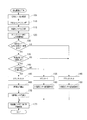
- FIG. 2 shows a flowchart of processing repeatedly executed by the control unit 6.
- the control unit 6 When the main power source (for example, IG: ignition) of the vehicle is on and the headlamp 1 is lit, the control unit 6 performs the process shown in FIG. 2 every time the vehicle travels a predetermined distance L (for example, 1 meter). It is designed to be executed repeatedly.
- IG ignition
- step 105 an output signal of an absolute pitch angle detected and output by the tilt sensor 4 is acquired.
- step 110 an output signal representing the atmospheric pressure value detected and output by the atmospheric pressure sensor 5 is acquired.
- step 115 the vehicle speed signal output from the vehicle speed sensor 3 is acquired.
- step 120 the unit travel distance after the counter reset is detected.
- the counter is a numerical value that is changed in steps 145, 155, and 165 described later.
- the travel distance after the counter reset is obtained by multiplying the counter value by the predetermined distance L.
- step 125 it is determined whether or not the atmospheric pressure fluctuation amount is within a certain value (specifically, the atmospheric pressure fluctuation reference value). Specifically, from the detected value of the atmospheric pressure sensor (for example, the detected value of the atmospheric pressure sensor acquired 10 times in the past) in the current step 110 and the previous N times (N is an integer of 1 or more) step 110, The most probable value (for example, by the method of least squares) is calculated as the amount of change in atmospheric pressure per unit travel distance (the value is positive when increasing or decreasing). Then, it is determined whether or not the calculated most probable fluctuation amount is smaller than the atmospheric pressure fluctuation reference value.
- the atmospheric pressure fluctuation reference value for example, the detected value of the atmospheric pressure sensor acquired 10 times in the past
- N is an integer of 1 or more
- a fluctuation value of 1.75 Pa per 100 m travel (that is, 1.75 ⁇ 10 ⁇ 2 Pa / m) is adopted. This is because it is determined whether or not the road gradient is within an angle range of ⁇ 0.1 ° or less with respect to the horizontal. That is, in step 125, it is determined whether or not the road gradient is within a predetermined range ( ⁇ 0.1 ° or less) with respect to the horizontal.
- step 105 when the iterative process including one cycle from step 105 to step 175 in FIG. 2 is the Nth time or less, a value larger than the atmospheric pressure fluctuation reference value is set as a provisional value of the atmospheric pressure fluctuation amount.
- the current time is the Nth or less, it is determined that the atmospheric pressure fluctuation amount is not within the atmospheric pressure fluctuation reference value (step 125: NO), and the process proceeds to step 145.
- step 145 the counter value is reset to zero.
- the previous value (the last updated value) is held as the value of the road surface pitch angle.
- the road surface pitch angle may be a predetermined initial value (for example, 0 °) as the previous value or updated last time during the previous traveling.
- the value may be read from a nonvolatile storage medium (for example, a flash memory included in the control unit 6).
- the control unit 6 is configured to record the road surface pitch angle calculated in step 170 described later on the storage medium.
- step 175 the optical axis direction of the headlamp 1 is controlled based on the current value of the road surface pitch angle. For example, if the road surface pitch angle is 0 °, the vertical direction of the optical axis is set as a predetermined reference optical axis direction.
- the reference optical axis direction is a direction fixed to the vehicle, and is, for example, a vehicle front-rear direction (a direction in which the optical axis is in front of the vehicle and in the horizontal direction when the vehicle is on a horizontal road surface).
- the left-right direction of the optical axis may be a fixed direction or may be changed according to the steering angle of the vehicle.
- Steps 105, 110, 115, 120, 125, 145, 150, and 175 are repeated in this order until Steps 105 to 175 are repeated N times.
- the outputs of the inclination sensor 4, the atmospheric pressure sensor 5, and the vehicle speed sensor 3 are acquired, and the absolute pitch angle, atmospheric pressure, and vehicle speed are accumulated in a storage medium such as a RAM. Meanwhile, the counter continues to be reset to zero (step 145), the road surface pitch angle is not updated (step 150), and the vertical direction of the optical axis does not change (step 175).
- Steps 105 to 175 for the (N + 1) th time after Steps 105, 110, 115, and 120, the atmospheric pressure is calculated based on the atmospheric pressure acquired from the atmospheric pressure sensor 5 at Step 125 and the previous N times and this time. It is determined whether or not the resulting fluctuation amount is within the atmospheric pressure fluctuation reference value.
- step 125 the determination result in step 125 is negative (step 125: NO), and then the process proceeds to step 145, where the counter value is reset to zero.
- step 150 the previous value is set as the value of the road surface pitch angle. Hold.
- step 175 the optical axis direction of the headlamp 1 is controlled based on the current value of the road surface pitch angle. However, since the road surface pitch angle is the same as the previous value, the vertical direction of the optical axis does not change.
- steps 105, 110, 115, 120, 125, 145, 150, and 175 are repeated in this order, and in each step 105, 110, 115, and 115,
- the outputs of the inclination sensor 4, the atmospheric pressure sensor 5, and the vehicle speed sensor 3 are acquired, and the absolute pitch angle, atmospheric pressure, and vehicle speed are accumulated in a storage medium such as a RAM.
- the counter continues to be reset to zero (step 145), the road surface pitch angle is not updated (step 150), and the vertical direction of the optical axis does not change (step 175).
- the atmospheric pressure is It is determined that the fluctuation amount is within the atmospheric pressure fluctuation reference value (step 125: YES).
- control unit 6 advances the process to step 130 to determine whether or not the absolute pitch angle variation obtained from the tilt sensor 4 is within a certain value (specifically, the absolute pitch angle reference variation). . Specifically, the standard deviation of the detected value of the absolute pitch angle in the current step 105 and the previous N steps 105 is calculated, and whether or not the calculated standard deviation is smaller than the absolute pitch angle reference fluctuation amount. Determine.
- the absolute pitch angle reference fluctuation amount is a reference value for determining whether or not the absolute pitch angle fluctuates suddenly when the vehicle travels on an uneven road and is, for example, 20 °. . This is because the road surface pitch angle is calculated when the vertical direction of the optical axis is controlled following the situation in which the vehicle travels on an uneven road and the absolute pitch angle changes rapidly. This is because it becomes inaccurate, and as a result, there is a high possibility that an appropriate direction cannot be irradiated.
- step 130 it is assumed that the absolute pitch angle fluctuation amount continues to be smaller than the absolute pitch angle reference fluctuation amount for a while after entering the horizontal road (step 130: YES). In that case, the control unit 6 advances the process to step 135.
- step 135 the change amount of the vehicle speed is calculated based on the vehicle speed pulse signal acquired from the vehicle speed sensor 3, and whether or not the calculated change amount of the vehicle speed is within a certain value (specifically, the reference speed change amount of the vehicle). Determine. Specifically, it is most probable as the amount of fluctuation in the vehicle speed per unit time (the value is positive if it increases or decreases) from the vehicle speed signal acquired in the current step 115 and the previous N steps 115. A value is calculated (for example, by the method of least squares). Then, it is determined whether or not the calculated most probable fluctuation amount is smaller than the vehicle speed reference fluctuation amount.
- a certain value specifically, the reference speed change amount of the vehicle.
- This vehicle speed reference fluctuation amount is a reference value for determining whether or not the influence of the inertial force appears in the detection result of the tilt sensor 4 due to acceleration / deceleration of the vehicle. / S 2 .
- step 140 it is assumed that the vehicle continues to travel at a constant speed for a while after entering the horizontal road, and the vehicle speed fluctuation amount is smaller than the vehicle speed reference fluctuation amount (step 135: YES). In that case, the control unit 6 advances the process to step 140.
- step 140 it is determined whether or not the travel distance calculated in step 120 is equal to or greater than a certain value (specifically, the reference travel distance).
- the reference travel distance is, for example, 100 meters.
- step 155 the counter value is incremented by one. Thereby, the value of the counter is changed from 0 to 1 in this example.
- step 160 the previous value is held as the value of the road surface pitch angle.
- step 175 the optical axis direction of the headlamp 1 is controlled based on the current value of the road surface pitch angle. Since the pitch angle is the same as the previous value, the vertical direction of the optical axis does not change.
- the control part 6 repeats the process of step 105,110,115,120,125,130,135,140,155,160,175 in this order.
- the value of the counter increases by one count for each distance L traveling.
- the control unit 6 determines in step 130 that the variation amount of the absolute pitch angle exceeds the absolute pitch angle reference variation amount (step 130: NO), and advances the processing to step 145.
- step 145 the counter is reset to zero, and in step 150, the previous value of the road surface pitch angle is held.
- step 175 the optical axis direction is controlled according to the road surface pitch angle. Does not change.
- the control part 6 repeats the process of step 105,110,115,120,125,130,135,140,155,160,175 in this order.
- the value of the counter increases from 0 by 1 count for each distance L travel.
- step 135 the control unit 6 determines in step 135 that the fluctuation amount of the vehicle speed exceeds the reference fluctuation amount of the vehicle speed (step 135: NO), and advances the processing to step 145.
- step 145 the counter is reset to zero.
- step 150 the previous value of the road surface pitch angle is held.
- step 175 the optical axis direction is controlled according to the road surface pitch angle. It does not change.
- the control part 6 repeats the process of step 105,110,115,120,125,130,135,140,155,160,175 in this order.
- the value of the counter increases from 0 by 1 count for each distance L travel.
- the value of the counter reaches or exceeds a value corresponding to the reference travel distance (that is, reference travel distance / L).
- step 140 determines in step 140 that the travel distance has exceeded the reference travel distance (step 140: YES), proceeds to step 165, resets the counter, and further proceeds to step 170 to calculate the road surface pitch angle.
- the road surface pitch angle is updated with the current value of the absolute pitch angle acquired in the immediately preceding step 105 (that is, step 105 in the current processing of steps 105 to 175). Thereby, the current value of the absolute pitch angle becomes the latest value of the road surface pitch angle.
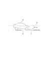
- the current absolute pitch angle ⁇ detected by the atmospheric pressure sensor 5 is the reference plane of the vehicle body.
- 11 is an angle with respect to the horizontal plane 13, and since the horizontal plane 13 is parallel to the road surface 12, the road surface pitch angle ⁇ formed by the reference plane 11 of the vehicle body with respect to the road surface 12 is the same value as the absolute pitch angle ⁇ .
- the reference plane 11 of the vehicle body is a surface fixed to the vehicle body, and is a surface parallel to the road surface 12 when the road surface pitch angle ⁇ of the vehicle body is zero.
- the cause of the occurrence of the road surface pitch angle such that the front of the vehicle body is tilted downward may be that the load on the front of the vehicle is very large.
- the optical axis direction of the headlamp 1 is controlled based on the current value of the road surface pitch angle. For example, if the road pitch angle is + 1 ° (a positive value indicates a pitch at which the vehicle nose sinks, and a negative value indicates a pitch at which the vehicle tail sinks), the influence of the road pitch angle is offset.
- the vertical direction of the optical axis is changed by ⁇ 1 ° (a positive value indicates a downward change and a negative value indicates an upward change) with respect to a predetermined reference optical axis direction. By doing so, the direction of the optical axis relative to the road surface can be stabilized even when the pitch angle to the road surface changes.
- step 105,110,115,120,125,130,135,140,155,160,175 the control part 6 repeats the process of step 105,110,115,120,125,130,135,140,155,160,175 in this order.
- the reason for proceeding from step 140 to step 155 is that the counter has been reset in step 165 as described above.
- the counter value is incremented by 1 for every distance L traveled from 0, and the updated road pitch angle is maintained, and the vertical direction of the optical axis corresponding to the road pitch angle is changed. Maintained.
- the control unit 6 of the present embodiment calculates the road surface pitch angle with respect to the road surface based on the acquired current value of the absolute pitch angle and the amount of atmospheric pressure fluctuation (corresponding to an example of a gradient-related amount). To do. That is, by calculating the road surface pitch based on the absolute pitch angle using the gradient-related amount that can specify the road surface gradient, the possibility of calculating an incorrect road surface pitch angle on a slope is reduced. be able to. Further, as described above, when the gradient-related amount changes according to the altitude (altitude) change, the road surface gradient can be specified based on the altitude fluctuation amount.
- control unit 6 determines whether or not the road surface gradient is within a predetermined range with respect to the horizontal based on the gradient-related amount, and when the road surface gradient is within the predetermined range with respect to the horizontal. If the current value of the absolute pitch angle is the latest value of the road surface pitch angle and the slope of the road surface is not within the specified range with respect to the horizontal, the current value of the absolute pitch angle is reflected in the road surface pitch angle. do not do.
- the current value of the absolute pitch angle is set to the road surface pitch angle.
- the slope of the road surface is not within the predetermined range with respect to the horizontal, the current value of the absolute pitch angle is not reflected in the road surface pitch angle. The possibility of calculation can be reduced.
- the road surface pitch angle changes when the load on the vehicle changes, such as when people get on and off, when loading and unloading, and when acceleration / deceleration occurs (that is, inertia force is generated in the vehicle). If any).
- the change of the road surface pitch angle due to the change of load balance does not occur so frequently, but once changed, the angle after the change is maintained for a while.
- a change in the road surface pitch angle due to acceleration / deceleration occurs relatively frequently, but has a characteristic that the duration of the change is short.
- the current value of the absolute pitch angle is set as the latest value of the road surface pitch angle, while the road surface pitch angle is updated when the road surface gradient is small, and the current value of the absolute pitch angle is updated when it is not small. Even if the value of is not reflected in the road surface pitch angle, it does not mean that the update of the road surface pitch angle is slow.
- the control unit 6 calculates the latest value of the road surface pitch angle, and the fluctuation amount of the vehicle speed is greater than the reference value (vehicle speed reference fluctuation amount). Is larger, the current value of the absolute pitch angle is not reflected in the road surface pitch angle, and the previous road surface pitch angle is maintained. By doing so, it is possible to reduce the possibility that the detection result of the inclination sensor 4 is affected by acceleration other than the acceleration or deceleration of the vehicle, that is, the influence other than the absolute pitch angle (specifically, the influence of inertial force). .
- steps having the same processing contents are given the same step numbers.
- the processing contents of the steps described in FIG. 2 and FIG. 4 will be omitted or simplified in the present embodiment.
- step 105 an output signal of an absolute pitch angle detected and output by the tilt sensor 4 is acquired.
- step 110 an output signal of the atmospheric pressure detected and output by the atmospheric pressure sensor 5 is acquired.
- step 115 the vehicle speed signal output from the vehicle speed sensor 3 is acquired.
- step 120 the travel distance after the counter reset is detected.
- step 130 the variation amount of the absolute pitch angle obtained from the tilt sensor 4 is within a certain value (specifically, the absolute pitch angle reference variation amount). It is determined whether or not. Specifically, based on the absolute pitch angle detection values in the current step 105 and the previous N steps 105, the amount of variation in the absolute pitch angle per unit travel distance (the value is positive regardless of whether it increases or decreases). ) As the most probable value (for example, by the method of least squares). Then, it is determined whether or not the calculated most probable fluctuation amount is smaller than the absolute pitch angle reference fluctuation amount.
- step 105 to step 175 in FIG. 4 When the process from step 105 to step 175 in FIG. 4 is repeated for the first time and this time is the Nth or less, a provisional value for the variation amount of the absolute pitch angle is set to a value larger than the absolute pitch angle variation reference value. To do. As a result, if the current time is the Nth or less, it is determined that the absolute pitch angle fluctuation amount is not within the absolute pitch angle fluctuation reference value (step 130: NO), and the process proceeds to step 145.
- step 145 the counter value is reset to zero, and in the subsequent step 150, the previous value is held as the value of the road surface pitch angle.
- the road surface pitch angle may be a predetermined initial value (for example, 0 °) as the previous value or updated last time during the previous traveling.
- the value may be read from a non-volatile storage medium.
- the control unit 6 is configured to record the road surface pitch angle calculated in step 170 described later on the storage medium.
- the optical axis direction of the headlamp 1 is controlled based on the current value of the road surface pitch angle.
- steps 105, 110, 115, 120, 130, 145, 150, and 175 are repeated in this order until the steps 105 to 175 are repeated N times.
- the outputs of the inclination sensor 4, the atmospheric pressure sensor 5, and the vehicle speed sensor 3 are acquired, and the absolute pitch angle, atmospheric pressure, and vehicle speed are accumulated in a storage medium such as a RAM. Meanwhile, the counter continues to be reset to zero (step 145), the road surface pitch angle is not updated (step 150), and the vertical direction of the optical axis does not change (step 175).
- Steps 105 to 175 for the (N + 1) th time after Steps 105, 110, 115, and 120, the absolute pitch is calculated based on the absolute pitch angle acquired from the tilt sensor 4 at Step 130 and the previous N times and this time.
- the angle variation amount can be calculated, and it is determined whether or not the resulting variation amount is within the absolute pitch angle variation reference value.
- step 130 the vehicle is still traveling on a slope (for example, 1 ° ascending slope), but is not traveling on a bumpy road surface, and the variation amount of the absolute pitch angle is smaller than the reference variation amount of the absolute pitch angle. Shall continue for a while. Therefore, the determination result in step 130 is affirmative (step 130: YES), and then the process proceeds to step 135.
- a slope for example, 1 ° ascending slope
- the variation amount of the absolute pitch angle is smaller than the reference variation amount of the absolute pitch angle. Shall continue for a while. Therefore, the determination result in step 130 is affirmative (step 130: YES), and then the process proceeds to step 135.
- step 135 the change amount of the vehicle speed is calculated based on the vehicle speed pulse signal acquired from the vehicle speed sensor 3, and whether or not the calculated change amount of the vehicle speed is within a certain value (specifically, the reference speed change amount of the vehicle). Determine.
- Step 135 the control unit 6 advances the process to step 140.
- step 140 it is determined whether or not the travel distance calculated in step 120 is equal to or greater than a certain value (specifically, the reference travel distance).
- the reference travel distance of the present embodiment may be 10 meters or 5.7 meters, for example. This amount of 5.7 meters corresponds to a travel distance in which the atmospheric pressure changes by 0.1 Pa (corresponding to a height difference of 1 cm) with a road surface gradient of 0.1 °.
- step 155 the counter value is incremented by one. Thereby, the value of the counter is changed from 0 to 1 in this example.
- step 160 the previous value is held as the value of the road surface pitch angle.
- step 175 the optical axis direction of the headlamp 1 is controlled based on the current value of the road surface pitch angle. Since the pitch angle is the same as the previous value, the vertical direction of the optical axis does not change.
- the control part 6 repeats the process of step 105,110,115,120,130,135,140,155,160,175 in this order.
- the value of the counter increases by one count for each distance L traveling.
- the value of the counter reaches or exceeds a value corresponding to the reference travel distance (that is, the reference travel distance / L) while traveling on the slope.
- Step 140 the control unit 6 determines that the travel distance has exceeded the reference travel distance (Step 140: YES), proceeds to Step 165, resets the counter, further proceeds to Step 168, and has completed the atmospheric pressure sensor until now. 5 is used to calculate the gradient of the road surface on which the vehicle is traveling.
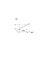
- the time T (the time from the time t1 before the current time by the time T1 to the current time t2, for example, The amount of decrease in atmospheric pressure per 100 milliseconds) is calculated, and the amount of increase in vehicle altitude H2-H1 per time T is calculated based on the calculation result.
- the control unit 6 calculates the atmospheric pressure decrease amount per time T based on the correspondence table of the atmospheric pressure decrease amount and the altitude increase amount recorded in the storage medium (for example, ROM) of the control unit 6 in advance. Then, the amount of increase in altitude H2-H1 per time T is calculated.
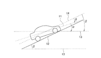
- a broken line 11 represents a vehicle reference plane
- a solid line 12 represents a road surface
- a broken line 13 represents a horizontal plane
- a broken line 14 represents a plane parallel to the road surface 12.
- step 170 the road surface pitch angle is calculated based on the road surface gradient calculated in step 173 and the absolute pitch angle calculated in the immediately preceding step 105.
- the current value of the road surface slope ⁇ calculated in the immediately preceding step 173 is obtained in the immediately preceding step 105.
- a value ⁇ obtained by subtracting the current absolute pitch angle ⁇ is set as the latest value of the road surface pitch angle ⁇ .
- step 175 the vertical direction of the optical axis of the headlamp 1 is controlled by the same method as in the first embodiment based on the latest value of the road surface pitch angle updated in the immediately preceding step 170.
- step 105,110,115,120,130,135,140,155,160,175 the control part 6 repeats the process of step 105,110,115,120,130,135,140,155,160,175 in this order.
- the reason for proceeding from step 140 to step 155 is that the counter has been reset in step 165 as described above.
- the counter value is incremented by 1 for every distance L traveled from 0, and the updated road pitch angle is maintained, and the vertical direction of the optical axis corresponding to the road pitch angle is changed. Maintained.
- step 130 the variation amount of the absolute pitch angle is the absolute pitch angle. It is determined that the angle fluctuation reference value is greater than the angle fluctuation reference value (step 130: NO), the process proceeds to step 145, and then the counter is reset. In step 150, the previous value of the road surface pitch angle is retained. Although the optical axis of the headlamp 1 is controlled based on the road surface pitch angle, the vertical direction of the optical axis does not change.
- the control part 6 repeats the process of step 105,110,115,120,130,135,140,155,160,175 in this order.
- the counter value is incremented by 1 for every distance L traveled from 0, and the updated road pitch angle is maintained, and the vertical direction of the optical axis corresponding to the road pitch angle is changed. Maintained.
- steps 105, 110, 115, 120, 130, 135, 140, 165, 168, 170, and 175 are executed in this order, and the difference ⁇ between the current absolute pitch angle ⁇ and the current road surface gradient ⁇ at that time is set as the latest value of the road surface pitch angle ⁇ , and the head according to the latest value.
- the vertical direction of the optical axis of the lamp 1 is controlled.
- the control unit 6 calculates the road surface pitch angle based on the acquired absolute value of the absolute pitch angle and the amount of atmospheric pressure fluctuation (corresponding to an example of a gradient related amount). In this way, by calculating the road surface pitch based on the absolute pitch angle using the gradient-related amount that can identify the road surface gradient, there is a possibility of calculating an incorrect road surface pitch angle on a slope. Can be reduced. Further, as described above, when the gradient-related amount is an amount that changes in accordance with a change in altitude, the road surface gradient can be specified based on the amount of change in altitude.
- control unit 6 sets the difference ⁇ between the road surface gradient ⁇ corresponding to the gradient related amount (specifically, atmospheric pressure) and the absolute pitch angle ⁇ as the road surface pitch angle ⁇ .
- the road surface pitch angle can be obtained by removing the influence of the road surface gradient from the absolute pitch angle.
- the road surface pitch angle can be detected even on a road other than a horizontal road, it is possible to control the optical axis direction following the road surface pitch angle that changes in a short time.
- the control unit 6 calculates the latest value of the road surface pitch angle, and the fluctuation amount of the vehicle speed is greater than the reference value (vehicle speed reference fluctuation amount). Is larger, the current value of the absolute pitch angle is not reflected in the road surface pitch angle, and the previous road surface pitch angle is maintained. By doing so, it is possible to reduce the possibility that the acceleration due to the acceleration / deceleration of the vehicle may have an influence other than the absolute pitch angle (specifically, the influence of inertial force) on the detection result of the inclination detecting means 4.
- control unit 6 functions as an example of an absolute pitch angle acquisition unit by executing Step 105, and functions as an example of a gradient related amount acquisition unit by executing Step 110.
- Executing 120 to 170 functions as an example of a road surface pitch angle calculating unit, and executing step 175 functions as an example of an optical axis control unit.
- the atmospheric pressure detected by the atmospheric pressure sensor 5 is adopted as the gradient-related amount that can specify the gradient of the road surface, but is not necessarily limited thereto.
- the altitude of the vehicle detected by a satellite navigation receiver for example, a GPS receiver or a satellite navigation receiver using a quasi-zenith satellite
- the altitude detection accuracy is about several centimeters.
- the altitude of the vehicle detected by the satellite navigation receiver corresponds to an example of an amount that changes in accordance with a change in the altitude of the vehicle, like the atmospheric pressure.
- the gradient related amount detection means and the atmospheric pressure sensor 5 are used, but a leveler may be used instead of the atmospheric pressure sensor 5.
- This leveler outputs a signal indicating whether or not the road surface is horizontal.
- the level must be installed at a position that is not affected by the pitch angle of the vehicle body. As such a position, for example, there is a suspension inside interposed between the vehicle body and the wheel.
- an acceleration sensor for example, a biaxial sensor, a triaxial sensor
- a capacitance method or a piezoresistive method that detects a change in the absolute pitch angle of the vehicle is used. May be.
Landscapes
- Engineering & Computer Science (AREA)
- Mechanical Engineering (AREA)
- Lighting Device Outwards From Vehicle And Optical Signal (AREA)
Priority Applications (2)
| Application Number | Priority Date | Filing Date | Title |
|---|---|---|---|
| DE112012004964.0T DE112012004964B4 (de) | 2011-11-30 | 2012-08-24 | Fahrzeugscheinwerfersteuervorrichtung und -verfahren und Fahrzeugscheinwerfersteuersystem |
| US14/361,373 US9868386B2 (en) | 2011-11-30 | 2012-08-24 | Vehicle headlight control device and method, and vehicle headlight control system |
Applications Claiming Priority (2)
| Application Number | Priority Date | Filing Date | Title |
|---|---|---|---|
| JP2011262054A JP5678873B2 (ja) | 2011-11-30 | 2011-11-30 | 車両用前照灯制御装置 |
| JP2011-262054 | 2011-11-30 |
Publications (1)
| Publication Number | Publication Date |
|---|---|
| WO2013080614A1 true WO2013080614A1 (ja) | 2013-06-06 |
Family
ID=48535091
Family Applications (1)
| Application Number | Title | Priority Date | Filing Date |
|---|---|---|---|
| PCT/JP2012/071490 Ceased WO2013080614A1 (ja) | 2011-11-30 | 2012-08-24 | 車両用前照灯制御装置及び方法、車両用前照灯制御システム |
Country Status (4)
| Country | Link |
|---|---|
| US (1) | US9868386B2 (https=) |
| JP (1) | JP5678873B2 (https=) |
| DE (1) | DE112012004964B4 (https=) |
| WO (1) | WO2013080614A1 (https=) |
Cited By (1)
| Publication number | Priority date | Publication date | Assignee | Title |
|---|---|---|---|---|
| US12391169B1 (en) | 2024-04-19 | 2025-08-19 | Alexandro De La Torre | Adjustable headlight device |
Families Citing this family (13)
| Publication number | Priority date | Publication date | Assignee | Title |
|---|---|---|---|---|
| JP5778587B2 (ja) * | 2012-01-11 | 2015-09-16 | スタンレー電気株式会社 | 車両用前照灯の光軸調整装置、車両用前照灯システム |
| JP2013180672A (ja) * | 2012-03-02 | 2013-09-12 | Stanley Electric Co Ltd | 車両用前照灯の光軸調整装置、車両用前照灯システム |
| FR3021605B1 (fr) * | 2014-06-03 | 2016-05-27 | Valeo Vision | Procede et systeme de correction de l’orientation des projecteurs d’un vehicule a moteur |
| US20160001695A1 (en) * | 2014-07-03 | 2016-01-07 | Memsic, Inc. | Method and apparatus for determining the inclination of a moving vehicle with respect to the road and for performing dynamic headlight leveling |
| CN107206928B (zh) * | 2015-01-14 | 2020-11-10 | 株式会社小糸制作所 | 车辆用灯具的控制装置和车辆用灯具系统 |
| CN104742796B (zh) * | 2015-03-13 | 2017-07-18 | 安徽天健环保车辆部件有限公司 | 一种自动灯光控制器 |
| US9574964B2 (en) * | 2015-07-07 | 2017-02-21 | Toyota Jidosha Kabushiki Kaisha | Mobile computer atmospheric barometric pressure system |
| JP6462557B2 (ja) * | 2015-11-06 | 2019-01-30 | 株式会社Soken | 車両ピッチ角推定装置 |
| JP6936624B2 (ja) | 2017-05-19 | 2021-09-15 | スタンレー電気株式会社 | 車両用灯具の制御装置および車両用灯具システム |
| WO2021186230A1 (en) * | 2020-03-16 | 2021-09-23 | Kumar S Nithin | Light management system of vehicle |
| CN113566777B (zh) * | 2020-04-29 | 2023-04-18 | 广州汽车集团股份有限公司 | 车辆俯仰角估计方法及其系统、计算机设备、存储介质 |
| CN113942445A (zh) * | 2020-07-15 | 2022-01-18 | 厦门雅迅网络股份有限公司 | 一种自适应前照灯控制方法、终端设备及存储介质 |
| WO2022201376A1 (ja) * | 2021-03-24 | 2022-09-29 | 三菱電機株式会社 | 車両姿勢角推定装置及び車両用灯具の光軸制御装置 |
Citations (4)
| Publication number | Priority date | Publication date | Assignee | Title |
|---|---|---|---|---|
| JPH06144108A (ja) * | 1992-11-13 | 1994-05-24 | Toyota Motor Corp | 車両用前照灯装置 |
| JPH1128975A (ja) * | 1997-07-11 | 1999-02-02 | Mitsubishi Motors Corp | 車両のヘッドランプの光軸調整装置 |
| JP2006027300A (ja) * | 2004-07-12 | 2006-02-02 | Koito Mfg Co Ltd | 車両用前照灯装置 |
| JP2011116201A (ja) * | 2009-12-02 | 2011-06-16 | Stanley Electric Co Ltd | ヘッドランプの光軸調整装置 |
Family Cites Families (7)
| Publication number | Priority date | Publication date | Assignee | Title |
|---|---|---|---|---|
| DE4437949C1 (de) | 1994-10-24 | 1996-04-04 | Daimler Benz Ag | Leuchtweitenregelung an einem Fahrzeug |
| JP3128609B2 (ja) | 1996-02-01 | 2001-01-29 | 株式会社小糸製作所 | 車輌用灯具の照射方向制御装置 |
| JP3384236B2 (ja) | 1996-04-22 | 2003-03-10 | 株式会社デンソー | 車両用前照灯光軸方向自動調整装置 |
| JP3995846B2 (ja) * | 1999-09-24 | 2007-10-24 | 本田技研工業株式会社 | 物体認識装置 |
| JP4726277B2 (ja) | 2000-05-31 | 2011-07-20 | 株式会社デンソー | 車両用前照灯光軸方向自動調整装置 |
| JP2002337600A (ja) | 2001-05-18 | 2002-11-27 | Ichikoh Ind Ltd | 車両用前照灯の光軸自動調整装置 |
| JP4840486B2 (ja) | 2009-08-07 | 2011-12-21 | 株式会社デンソー | ライト制御装置 |
-
2011
- 2011-11-30 JP JP2011262054A patent/JP5678873B2/ja not_active Expired - Fee Related
-
2012
- 2012-08-24 US US14/361,373 patent/US9868386B2/en not_active Expired - Fee Related
- 2012-08-24 WO PCT/JP2012/071490 patent/WO2013080614A1/ja not_active Ceased
- 2012-08-24 DE DE112012004964.0T patent/DE112012004964B4/de not_active Expired - Fee Related
Patent Citations (4)
| Publication number | Priority date | Publication date | Assignee | Title |
|---|---|---|---|---|
| JPH06144108A (ja) * | 1992-11-13 | 1994-05-24 | Toyota Motor Corp | 車両用前照灯装置 |
| JPH1128975A (ja) * | 1997-07-11 | 1999-02-02 | Mitsubishi Motors Corp | 車両のヘッドランプの光軸調整装置 |
| JP2006027300A (ja) * | 2004-07-12 | 2006-02-02 | Koito Mfg Co Ltd | 車両用前照灯装置 |
| JP2011116201A (ja) * | 2009-12-02 | 2011-06-16 | Stanley Electric Co Ltd | ヘッドランプの光軸調整装置 |
Cited By (1)
| Publication number | Priority date | Publication date | Assignee | Title |
|---|---|---|---|---|
| US12391169B1 (en) | 2024-04-19 | 2025-08-19 | Alexandro De La Torre | Adjustable headlight device |
Also Published As
| Publication number | Publication date |
|---|---|
| US20140286025A1 (en) | 2014-09-25 |
| DE112012004964T5 (de) | 2014-08-21 |
| US9868386B2 (en) | 2018-01-16 |
| JP5678873B2 (ja) | 2015-03-04 |
| JP2013112267A (ja) | 2013-06-10 |
| DE112012004964B4 (de) | 2022-07-28 |
Similar Documents
| Publication | Publication Date | Title |
|---|---|---|
| JP5678873B2 (ja) | 車両用前照灯制御装置 | |
| US9771073B2 (en) | Adaptive cruise control system in vehicle and method thereof | |
| JP6073535B2 (ja) | 前照灯用光軸制御装置 | |
| EP2664494B1 (en) | Control device for vehicle lamp and vehicle lamp system | |
| EP2529976B1 (en) | Vehicle lamp control device and vehicle lamp system | |
| JP2011116201A (ja) | ヘッドランプの光軸調整装置 | |
| JP2000062525A (ja) | 車輌用灯具の照射方向制御装置 | |
| WO2016013419A1 (ja) | 車両用前照灯制御装置 | |
| US9902201B2 (en) | Method and devices for detecting and rectifying problems in connection with a vehicle load | |
| KR102542377B1 (ko) | 자동차의 글로벌 경사를 결정하기 위한 자율 방법 및 장치 | |
| JPWO2016189707A1 (ja) | 前照灯用光軸制御装置 | |
| KR20170070944A (ko) | 가속도 센서 및 자이로 센서를 이용한 차량 피치각 검출 장치 및 그 방법 | |
| JP6742696B2 (ja) | 自動車両のヘッドライトの配向を補正するための方法とシステム | |
| JP6362815B2 (ja) | 前照灯用光軸制御装置 | |
| JP2014047626A (ja) | 車両用制御装置 | |
| JP6614112B2 (ja) | 前照灯制御装置 | |
| JP7162114B2 (ja) | 車両用灯具の制御装置および車両用灯具システム | |
| JP2013129284A (ja) | ピッチング角処理装置 | |
| WO2013180113A1 (ja) | 路面に対する車両の傾斜を検出する装置及びその方法 | |
| US20040114382A1 (en) | Projecting direction control system for vehicle headlamp | |
| WO2019097724A1 (ja) | 傾斜角度計測装置及び光軸制御装置 | |
| JP6417098B2 (ja) | 車両姿勢制御装置 | |
| CN108928291A (zh) | 车辆用灯具的控制装置和车辆用灯具系统 | |
| KR102202202B1 (ko) | 가속도 센서 및 자이로 센서를 이용한 차량 피치각 검출 장치 및 그 방법 | |
| JP7470147B2 (ja) | 車両用制御装置 |
Legal Events
| Date | Code | Title | Description |
|---|---|---|---|
| 121 | Ep: the epo has been informed by wipo that ep was designated in this application |
Ref document number: 12852814 Country of ref document: EP Kind code of ref document: A1 |
|
| WWE | Wipo information: entry into national phase |
Ref document number: 14361373 Country of ref document: US |
|
| WWE | Wipo information: entry into national phase |
Ref document number: 112012004964 Country of ref document: DE Ref document number: 1120120049640 Country of ref document: DE |
|
| 122 | Ep: pct application non-entry in european phase |
Ref document number: 12852814 Country of ref document: EP Kind code of ref document: A1 |