WO2013073565A1 - 厚鋼板の高能率溶接方法 - Google Patents
厚鋼板の高能率溶接方法 Download PDFInfo
- Publication number
- WO2013073565A1 WO2013073565A1 PCT/JP2012/079492 JP2012079492W WO2013073565A1 WO 2013073565 A1 WO2013073565 A1 WO 2013073565A1 JP 2012079492 W JP2012079492 W JP 2012079492W WO 2013073565 A1 WO2013073565 A1 WO 2013073565A1
- Authority
- WO
- WIPO (PCT)
- Prior art keywords
- welding
- less
- electrode
- groove
- flux
- Prior art date
- Legal status (The legal status is an assumption and is not a legal conclusion. Google has not performed a legal analysis and makes no representation as to the accuracy of the status listed.)
- Ceased
Links
Images


Classifications
-
- B—PERFORMING OPERATIONS; TRANSPORTING
- B23—MACHINE TOOLS; METAL-WORKING NOT OTHERWISE PROVIDED FOR
- B23K—SOLDERING OR UNSOLDERING; WELDING; CLADDING OR PLATING BY SOLDERING OR WELDING; CUTTING BY APPLYING HEAT LOCALLY, e.g. FLAME CUTTING; WORKING BY LASER BEAM
- B23K9/00—Arc welding or cutting
- B23K9/18—Submerged-arc welding
- B23K9/186—Submerged-arc welding making use of a consumable electrodes
- B23K9/188—Submerged-arc welding making use of a consumable electrodes making use of several electrodes
-
- B—PERFORMING OPERATIONS; TRANSPORTING
- B23—MACHINE TOOLS; METAL-WORKING NOT OTHERWISE PROVIDED FOR
- B23K—SOLDERING OR UNSOLDERING; WELDING; CLADDING OR PLATING BY SOLDERING OR WELDING; CUTTING BY APPLYING HEAT LOCALLY, e.g. FLAME CUTTING; WORKING BY LASER BEAM
- B23K35/00—Rods, electrodes, materials, or media, for use in soldering, welding, or cutting
- B23K35/22—Rods, electrodes, materials, or media, for use in soldering, welding, or cutting characterised by the composition or nature of the material
- B23K35/24—Selection of soldering or welding materials proper
- B23K35/30—Selection of soldering or welding materials proper with the principal constituent melting at less than 1550°C
- B23K35/3053—Fe as the principal constituent
-
- B—PERFORMING OPERATIONS; TRANSPORTING
- B23—MACHINE TOOLS; METAL-WORKING NOT OTHERWISE PROVIDED FOR
- B23K—SOLDERING OR UNSOLDERING; WELDING; CLADDING OR PLATING BY SOLDERING OR WELDING; CUTTING BY APPLYING HEAT LOCALLY, e.g. FLAME CUTTING; WORKING BY LASER BEAM
- B23K35/00—Rods, electrodes, materials, or media, for use in soldering, welding, or cutting
- B23K35/22—Rods, electrodes, materials, or media, for use in soldering, welding, or cutting characterised by the composition or nature of the material
- B23K35/24—Selection of soldering or welding materials proper
- B23K35/30—Selection of soldering or welding materials proper with the principal constituent melting at less than 1550°C
- B23K35/3053—Fe as the principal constituent
- B23K35/3093—Fe as the principal constituent with other elements as next major constituents
-
- B—PERFORMING OPERATIONS; TRANSPORTING
- B23—MACHINE TOOLS; METAL-WORKING NOT OTHERWISE PROVIDED FOR
- B23K—SOLDERING OR UNSOLDERING; WELDING; CLADDING OR PLATING BY SOLDERING OR WELDING; CUTTING BY APPLYING HEAT LOCALLY, e.g. FLAME CUTTING; WORKING BY LASER BEAM
- B23K35/00—Rods, electrodes, materials, or media, for use in soldering, welding, or cutting
- B23K35/22—Rods, electrodes, materials, or media, for use in soldering, welding, or cutting characterised by the composition or nature of the material
- B23K35/36—Selection of non-metallic compositions, e.g. coatings or fluxes; Selection of soldering or welding materials, conjoint with selection of non-metallic compositions, both selections being of interest
- B23K35/3601—Selection of non-metallic compositions, e.g. coatings or fluxes; Selection of soldering or welding materials, conjoint with selection of non-metallic compositions, both selections being of interest with inorganic compounds as principal constituents
- B23K35/3602—Carbonates, basic oxides or hydroxides
-
- B—PERFORMING OPERATIONS; TRANSPORTING
- B23—MACHINE TOOLS; METAL-WORKING NOT OTHERWISE PROVIDED FOR
- B23K—SOLDERING OR UNSOLDERING; WELDING; CLADDING OR PLATING BY SOLDERING OR WELDING; CUTTING BY APPLYING HEAT LOCALLY, e.g. FLAME CUTTING; WORKING BY LASER BEAM
- B23K35/00—Rods, electrodes, materials, or media, for use in soldering, welding, or cutting
- B23K35/22—Rods, electrodes, materials, or media, for use in soldering, welding, or cutting characterised by the composition or nature of the material
- B23K35/36—Selection of non-metallic compositions, e.g. coatings or fluxes; Selection of soldering or welding materials, conjoint with selection of non-metallic compositions, both selections being of interest
- B23K35/3601—Selection of non-metallic compositions, e.g. coatings or fluxes; Selection of soldering or welding materials, conjoint with selection of non-metallic compositions, both selections being of interest with inorganic compounds as principal constituents
- B23K35/3607—Silica or silicates
-
- B—PERFORMING OPERATIONS; TRANSPORTING
- B23—MACHINE TOOLS; METAL-WORKING NOT OTHERWISE PROVIDED FOR
- B23K—SOLDERING OR UNSOLDERING; WELDING; CLADDING OR PLATING BY SOLDERING OR WELDING; CUTTING BY APPLYING HEAT LOCALLY, e.g. FLAME CUTTING; WORKING BY LASER BEAM
- B23K35/00—Rods, electrodes, materials, or media, for use in soldering, welding, or cutting
- B23K35/22—Rods, electrodes, materials, or media, for use in soldering, welding, or cutting characterised by the composition or nature of the material
- B23K35/36—Selection of non-metallic compositions, e.g. coatings or fluxes; Selection of soldering or welding materials, conjoint with selection of non-metallic compositions, both selections being of interest
- B23K35/3601—Selection of non-metallic compositions, e.g. coatings or fluxes; Selection of soldering or welding materials, conjoint with selection of non-metallic compositions, both selections being of interest with inorganic compounds as principal constituents
- B23K35/361—Alumina or aluminates
-
- B—PERFORMING OPERATIONS; TRANSPORTING
- B23—MACHINE TOOLS; METAL-WORKING NOT OTHERWISE PROVIDED FOR
- B23K—SOLDERING OR UNSOLDERING; WELDING; CLADDING OR PLATING BY SOLDERING OR WELDING; CUTTING BY APPLYING HEAT LOCALLY, e.g. FLAME CUTTING; WORKING BY LASER BEAM
- B23K35/00—Rods, electrodes, materials, or media, for use in soldering, welding, or cutting
- B23K35/22—Rods, electrodes, materials, or media, for use in soldering, welding, or cutting characterised by the composition or nature of the material
- B23K35/36—Selection of non-metallic compositions, e.g. coatings or fluxes; Selection of soldering or welding materials, conjoint with selection of non-metallic compositions, both selections being of interest
- B23K35/362—Selection of compositions of fluxes
-
- B—PERFORMING OPERATIONS; TRANSPORTING
- B23—MACHINE TOOLS; METAL-WORKING NOT OTHERWISE PROVIDED FOR
- B23K—SOLDERING OR UNSOLDERING; WELDING; CLADDING OR PLATING BY SOLDERING OR WELDING; CUTTING BY APPLYING HEAT LOCALLY, e.g. FLAME CUTTING; WORKING BY LASER BEAM
- B23K9/00—Arc welding or cutting
- B23K9/23—Arc welding or cutting taking account of the properties of the materials to be welded
-
- C—CHEMISTRY; METALLURGY
- C22—METALLURGY; FERROUS OR NON-FERROUS ALLOYS; TREATMENT OF ALLOYS OR NON-FERROUS METALS
- C22C—ALLOYS
- C22C38/00—Ferrous alloys, e.g. steel alloys
-
- C—CHEMISTRY; METALLURGY
- C22—METALLURGY; FERROUS OR NON-FERROUS ALLOYS; TREATMENT OF ALLOYS OR NON-FERROUS METALS
- C22C—ALLOYS
- C22C38/00—Ferrous alloys, e.g. steel alloys
- C22C38/02—Ferrous alloys, e.g. steel alloys containing silicon
-
- C—CHEMISTRY; METALLURGY
- C22—METALLURGY; FERROUS OR NON-FERROUS ALLOYS; TREATMENT OF ALLOYS OR NON-FERROUS METALS
- C22C—ALLOYS
- C22C38/00—Ferrous alloys, e.g. steel alloys
- C22C38/04—Ferrous alloys, e.g. steel alloys containing manganese
-
- C—CHEMISTRY; METALLURGY
- C22—METALLURGY; FERROUS OR NON-FERROUS ALLOYS; TREATMENT OF ALLOYS OR NON-FERROUS METALS
- C22C—ALLOYS
- C22C38/00—Ferrous alloys, e.g. steel alloys
- C22C38/08—Ferrous alloys, e.g. steel alloys containing nickel
-
- C—CHEMISTRY; METALLURGY
- C22—METALLURGY; FERROUS OR NON-FERROUS ALLOYS; TREATMENT OF ALLOYS OR NON-FERROUS METALS
- C22C—ALLOYS
- C22C38/00—Ferrous alloys, e.g. steel alloys
- C22C38/12—Ferrous alloys, e.g. steel alloys containing tungsten, tantalum, molybdenum, vanadium, or niobium
-
- C—CHEMISTRY; METALLURGY
- C22—METALLURGY; FERROUS OR NON-FERROUS ALLOYS; TREATMENT OF ALLOYS OR NON-FERROUS METALS
- C22C—ALLOYS
- C22C38/00—Ferrous alloys, e.g. steel alloys
- C22C38/14—Ferrous alloys, e.g. steel alloys containing titanium or zirconium
Definitions
- the present invention relates to a welding technique capable of efficiently welding a foundation portion of a wind power generation facility installed in a cold region.
- Steel materials having a tensile strength of 450 MPa or more and 650 MPa or less are often used, and in particular, thick steel plates having a tensile strength of 480 MPa or more and 620 MPa or less are often used.
- Economic rationality is important for whether wind power generation will become widespread in the future. From this point of view, it is an important issue to reduce the construction cost in the foundation of wind power generation, and it is required to weld such a thick steel plate with high efficiency in the field of welding.
- Patent Document 1 discloses a submerged arc welding method capable of welding a thick steel plate having a thickness of 70 mm with one layer on one side.
- this method is single-sided welding, the groove cross-sectional area is very wide and the welding heat input is very high at 780 kJ / cm.
- the toughness of the weld metal is not disclosed, but it is considered that it corresponds to the toughness at 0 ° C. considering that it is for architectural use, and is not suitable for use in cold regions.
- Patent Document 2 the building is subjected to large heat input submerged arc welding for box columns.
- the Charpy test of the weld metal is only evaluated at ⁇ 5 ° C., and it is presumed that the heat input is excessive because it is a single-sided weld as in Patent Document 1.
- the groove cross-sectional area In order to ensure the toughness of the weld metal, it is effective not to use unnecessarily large heat input by making the groove cross-sectional area as narrow as possible. In order to suppress the groove cross-sectional area, it is possible to suppress the groove cross-sectional area by processing the groove from both the front and back sides of the steel material, such as the X groove, rather than processing the groove from one side. The following is known as a technique related to the double-sided single-layer welding method using such an X groove.
- Patent Document 3 discloses the examination results up to a plate thickness of 38 mm as a method for producing a welded steel pipe by double-sided single-layer welding.
- a plate thickness of 50 mm is studied by double-sided single-layer welding.
- Patent Document 4 is also insufficient knowledge.
- patent document 5 it is supposed that the technique which can weld a plate
- knowledge up to 31.8 mm and is not knowledge applicable to the field of wind power generation.
- FIG. 1 An example of the waveform of the rectangular wave AC welding current output by such a power supply is shown in FIG.
- the welding current has a plus part and a minus part.
- the positive polarity reverse polarity
- the negative polarity positive polarity
- the current waveform size a, b and width (period) c, d can be freely changed, by changing the size of the plus portion and minus portion, The penetration depth or the amount of welding can be adjusted.
- Patent Document 7 discloses one-layer one-pass welding based on multi-layer welding. However, it is not a welding method in which an extremely thick steel plate is applied with high efficiency by high heat input welding, and knowledge that can drastically improve the welding efficiency of an extremely thick steel plate such as wind power generation cannot be obtained from Patent Document 7.
- each groove is only one layer, one pass, ie, one side, by multi-electrode submerged arc welding.
- welding by a pass it is not known what type of molten material and welding conditions are preferable from the viewpoint of improving the wire feed speed and suppressing the heat input.
- Japanese Unexamined Patent Publication No. 9-206946 Japanese Patent Laid-Open No. 9-277083 Japanese Unexamined Patent Publication No. 2009-241128 Japanese Unexamined Patent Publication No. 2009-195957 Japanese Unexamined Patent Publication No. 2004-143556 Japanese Unexamined Patent Publication No. 2005-193299 Japanese Unexamined Patent Publication No. 2011-200920
- the present invention provides a submerged arc welding method that can weld a X-groove of a thick steel plate with high efficiency using a welding power source capable of controlling the output waveform, and can obtain a weld metal having excellent toughness even at low temperatures. This is the issue.
- the inventors of the present invention examined welding conditions that can increase the wire feed speed with the same welding current when welding the groove in one pass by multi-electrode submerged arc welding using a welding power source capable of controlling the output waveform. .
- a welding power source capable of controlling the output waveform.
- the submerged arc welding method includes a processing step of machining an X groove into a pair of steel materials having a plate thickness of more than 50 mm and 100 mm or less; A multi-electrode submerged arc welding of at least 6 electrodes and at most 6 electrodes, and a welding step in which one pass is welded from the front and back surfaces using a flux.
- the welding current of the first electrode is The welding current of the other electrodes is welded as an alternating current with a waveform ratio of 70% or more or a negative direct current, and the flux is the same as that of the flux.
- the mass ratio with respect to the total mass includes Al 2 O 3 : 10% or more and 50% or less, SiO 2 : 16% or more and 30% or less, and MgO, TiO 2 , CaF 2 and MnO. 1 type or more in total containing 10% or more and 60% or less, limiting the MgO to 40% or less, limiting the TiO 2 to 20% or less, limiting the CaF 2 to 30% or less, Limit MnO to 20% or less.
- the welding current of the first electrode may be 2500 A or more.
- a plurality of groove shapes formed between the pair of steel materials, the height of the root face is 5 mm or more, and 25% of the plate thickness It may be the following.
- a groove angle of the X groove may be 30 ° or more and 50 ° or less.
- a groove angle of the X groove may be 30 ° or more and 50 ° or less.
- a weld metal that can weld the X groove of the thick steel plate with high efficiency and is excellent in toughness even at low temperatures can be obtained.
- the basic part of the wind power generation facility can be manufactured efficiently, which can greatly contribute to the spread of renewable energy.
- the inventors of the present invention use a welding power source capable of controlling the output waveform to open the front and rear surfaces of the X-groove of the thick steel plate by multi-electrode submerged arc welding (hereinafter, submerged arc welding is abbreviated as SAW).
- SAW multi-electrode submerged arc welding
- the present inventors conducted the following experimental investigation on the components of the flux.
- the SAW flux is formed by blending various substances such as oxides and fluorides.
- the flux composed of each substance alone is subjected to an experiment, and the influence on the wire feeding speed is examined. investigated.
- Submerged arc welding was performed using a rectangular wave AC welding current as shown in FIG. The result is shown in FIG.
- the waveform ratio used in FIG. 1 is a positive / negative area ratio of alternating current as shown in Equation 1 and FIG. 2, where the positive area is P and the negative area is N.
- the numerical value represented by N / (N + P) is converted to%.
- a waveform ratio of 0% means a direct current plus, and a waveform ratio of 100% means a direct current minus.
- Waveform ratio area N / (area N + area P) (1)
- the flux design guideline for increasing the wire feed rate and increasing the welding amount contains Al 2 O 3 and SiO 2 as essential components, and includes MgO, TiO 2 and CaF 2. , Was found to contain selectively MnO.
- each component was examined and determined as follows.
- the contents of essential substances Al 2 O 3 and SiO 2 are mass% with respect to the total mass of the flux (hereinafter, all components of the flux are expressed in mass% with respect to the total mass of the flux), and Al 2 O 3 is 10%. more, 50% or less, SiO 2 of 16% or more was 30% or less.
- the lower limit values of 10% and 16% of Al 2 O 3 and SiO 2 were defined because the effect of increasing the wire feeding speed was not clearly exhibited at a lower content.
- the lower limit of Al 2 O 3 may be 15%, 20%, 25%, or 30%, and the lower limit of SiO 2 may be 18% or 20%.
- the upper limit if Al 2 O 3 is contained in an amount exceeding 50%, the amount of Al in the weld metal 8 becomes excessive and low temperature toughness cannot be secured, so the upper limit was set to 50%.
- the upper limit may be limited to 47%, 45% or 40%.
- the upper limit In SiO 2 , if the content exceeds 30%, the oxygen content of the weld metal 8 becomes excessive and it is difficult to ensure low temperature toughness, so the upper limit was made 30%. In order to improve low temperature toughness, the upper limit may be limited to 28% or 26%.
- SiO 2 is contained in an amount of 22% or more, the effect of improving the wire feeding speed when the waveform ratio is increased by the combined action of Al 2 O 3 and SiO 2 becomes even more preferable.
- FIG. 5 shows the experimental results regarding the combined action of Al 2 O 3 and SiO 2 for the effect of improving the wire feed speed when 38% Al 2 O 3 is contained.
- the total amount of Al 2 O 3 and SiO 2 may be limited to 30% or more and 80% or less.
- the lower limit of the total amount of Al 2 O 3 and SiO 2 may be set to 35%, 40% or 45%, and the upper limit of the total amount is set to 75%, 70% or 68%. Also good.
- the flux used in the present invention is further made of MgO, TiO 2 , CaF 2 , MnO as one or more selected materials, MgO: 40% or less, TiO 2 : 20 %, CaF 2 : 30% or less, and MnO: 20% or less, the total of these selected substances must be contained in the range of 10% or more and 60% or less.
- These materials are less effective in improving the wire feed speed than Al 2 O 3 and SiO 2 , but there is no adverse effect of decreasing the wire feed speed when the waveform ratio is increased like ZrO 2 , and slag It is necessary to contain an appropriate amount from the viewpoint of optimizing the fluidity and viscosity of the. From the viewpoint of optimizing the fluidity and viscosity of the slag, the lower limit of the total amount of these selected substances may be 13%, 15% or 20%, and the upper limit of the total amount may be 55%, 50% or 45%. Good.
- the upper limit of TiO 2 and MnO may be limited to 15% or 10%, respectively.
- the upper limit of CaF 2 may be limited to 25%, 20%, or 15%.
- the total content of these selected substances when the total content of these selected substances is less than 10%, since the effect of slag fluidity and viscosity optimization is not clear, undercut is likely to occur, so the lower limit is 10% did.
- the total content of these selected substances may be 13% or more, 16% or more, or 20% or more. If the content exceeds 60%, the arc becomes unstable and poor fusion tends to occur. Therefore, the total content is set to 60% or less. In order to prevent poor fusion, the total content of these selected substances may be limited to 55% or less, 50% or less, or 45% or less.
- the component generally used as a flux component for SAW can be contained suitably.
- metal powders such as Si, Mn, Al, Ti, Mo, Cu, Ni, Cr, and V may be contained in the flux for the purpose of adjusting the components of the weld metal 8. These contents can be appropriately adjusted with reference to the above-mentioned patent documents.
- iron powder in the flux for the purpose of increasing the amount of welding and stabilizing the arc.
- the iron powder content is preferably 10% or more and 40% or less. If added in a large amount, the arc is likely to be unstable, and the arc is likely to be interrupted during welding. Therefore, the upper limit of the content may be 30%, 20%, or 15% or less as necessary.
- Patent Document 6 describes an example in which direct current is used for the first electrode 1 in order to obtain a necessary penetration depth.
- 6A shows the penetration shape of the weld metal 8 obtained as a result of performing double-sided one-pass SAW of the X groove with the first electrode 1 as a direct current plus.
- the groove angle was set to 30 ° from the viewpoint of heat input suppression, but the arc could be disturbed due to the effect of residual magnetism of the steel material, and the case where the center of the penetration shape of the weld metal 8 did not coincide on the front and back surfaces was observed. .
- this method is considered to be an effective method in the case of single-sided welding that requires deep penetration, and is difficult to apply in double-sided welding with an X groove, which is not practical.
- the penetration shape of the weld metal 8 when an AC welding current having a waveform ratio of 60% between the plus part and the minus part is applied to the first electrode 1 is shown in FIG. 6B.
- the penetration depth is smaller than when the first electrode 1 is a DC plus.
- the bead width is increased and the center of the weld metal 8 on both sides of the front and back surfaces is shifted, poor fusion hardly occurs, and it has been found that this waveform control is preferable.
- the arc may become unstable due to the effect of high residual magnetism, and thus is excluded from the scope of the present invention.
- the welding current waveform of the first electrode 1 is preferably a welding current waveform that has an effect of improving the wire feed speed and can easily avoid poor fusion even in a narrow groove.
- an alternating current having a waveform ratio of 60% or more and 90% or less was set as a condition.
- the lower limit of the waveform ratio may be 65%, 68%, or 71%
- the upper limit of the waveform ratio may be 85%, 82%, or 78%. Data obtained by verifying this in more detail is shown in FIGS. In the groove of FIG.
- the conditions of the first electrode 1 were set to 2500 A and 35 V, the second electrode 2 and subsequent electrodes were fixed at 1500 A and 40 V, and the waveform ratio was fixed at 90%, and an arc was generated under welding conditions of 50 cm / min. .
- the weld length of 5 m was produced by changing the waveform ratio of the first electrode 1, and 50 macro sections were cut out at intervals of 10 cm to confirm the presence or absence of poor fusion at the root face (root surface) portion.
- the evaluation was 1/50 if there was one fusion failure in 50 macros, and was evaluated as a fusion failure occurrence rate of 2%. From FIG. 7 to FIG.
- the waveform ratio of the first electrode 1 is 60% or more and 90% or less, and the fusion failure occurrence rate is suppressed. It has been confirmed. Further, the second electrode 2 and the subsequent electrodes do not have a great influence on the penetration shape of the weld metal 8, and it is only necessary to consider the improvement of the wire feed speed. Therefore, the waveform ratio is 70 for all the electrodes 7 after the second electrode 2. % Or more (including DC minus with a waveform ratio of 100%). In order to improve the wire feeding speed, the waveform ratio may be 75% or more, 80% or more, or 85% or more.
- the number of electrodes used for welding is 2 or more and 6 or less from the viewpoint of ensuring a certain degree of productivity (welding speed) and avoiding excessively complicated equipment configuration.
- the number of electrodes may be three electrodes or four or more, or the thickness of the steel material may be 55 mm or more, 60 mm or more, or 65 mm or more.
- FIGS. The results of detailed investigations regarding the waveform ratio after the second electrode 2 are shown in FIGS.
- the groove of FIG. 10 was used for 6-electrode welding
- the groove of FIG. 14 was used for 4-electrode welding
- the groove of FIG. 15 was used for 2-electrode welding.
- the conditions of the first electrode 1 were 2500 A, 35 V, and the waveform ratio was 70%.
- the waveform ratio was changed at 1800A and 40V.
- the welding speed was 50 cm / min.
- a welding length of 5 m was produced by changing the waveform ratio, and 50 macro sections were cut out at intervals of 10 cm to confirm the presence or absence of underfill. Evaluation was performed by the ratio of the macro test piece in which underfill occurred. For example, if there is one underfill in 50 macros, it was evaluated as an underfill occurrence rate of 2%. From FIG. 11 to FIG. 13, it was confirmed that the underfill decreased as the waveform ratio increased, and that the required amount of welding could be obtained without changing the heat input.
- the electrodes 7 are arranged at the center of the groove width with the interval between the electrodes 7 being 70 mm as shown in FIG.
- the first electrode angle is 10 °
- the second electrode angle is 7 °
- the third electrode angle is 4 °
- the fourth electrode angle is 4 °
- the fifth electrode angle is 5 °.
- the angle of the electrode was 7 °
- the angle of the sixth electrode (final pole) was 10 °.
- the range of application of the steel plate thickness according to the present invention as described above is set to more than 50 mm and not more than 100 mm in consideration of the steel plate thickness used for the foundation portion of the wind turbine of the wind power generator. Since the effect of the present invention can be exhibited particularly by welding of steel materials having a plate thickness of more than 50 mm, the lower limit is set to more than 50 mm. However, if the plate thickness exceeds 100 mm, even if the present invention is applied, the heat input becomes excessive and the required toughness cannot be obtained.
- the root face (specifically, the height of the root face) is preferably 5 mm or more and 25% or less of the plate thickness.
- the reason for this is that if the height is 5 mm or less, there is a possibility that it is not possible to deal with misunderstandings from the viewpoint of work accuracy. If the height exceeds 25% of the plate thickness, the root face becomes excessively large, resulting in poor fusion. Is more likely to occur.
- the height of the root face refers to the height of the root face in the thickness direction of the steel material. For example, in FIG. 10, the height of the root face is 14 mm.
- the groove angle is preferably 30 ° or more and 50 ° or less from the viewpoint of suppressing heat input.
- the X-groove is processed into a pair of steel materials having a plate thickness of more than 50 mm and 100 mm or less, and this is defined in the present invention when performing one-pass welding from the front and back surfaces by multi-electrode submerged arc welding.
- the feasibility and effects of the present invention will be further described in the examples.
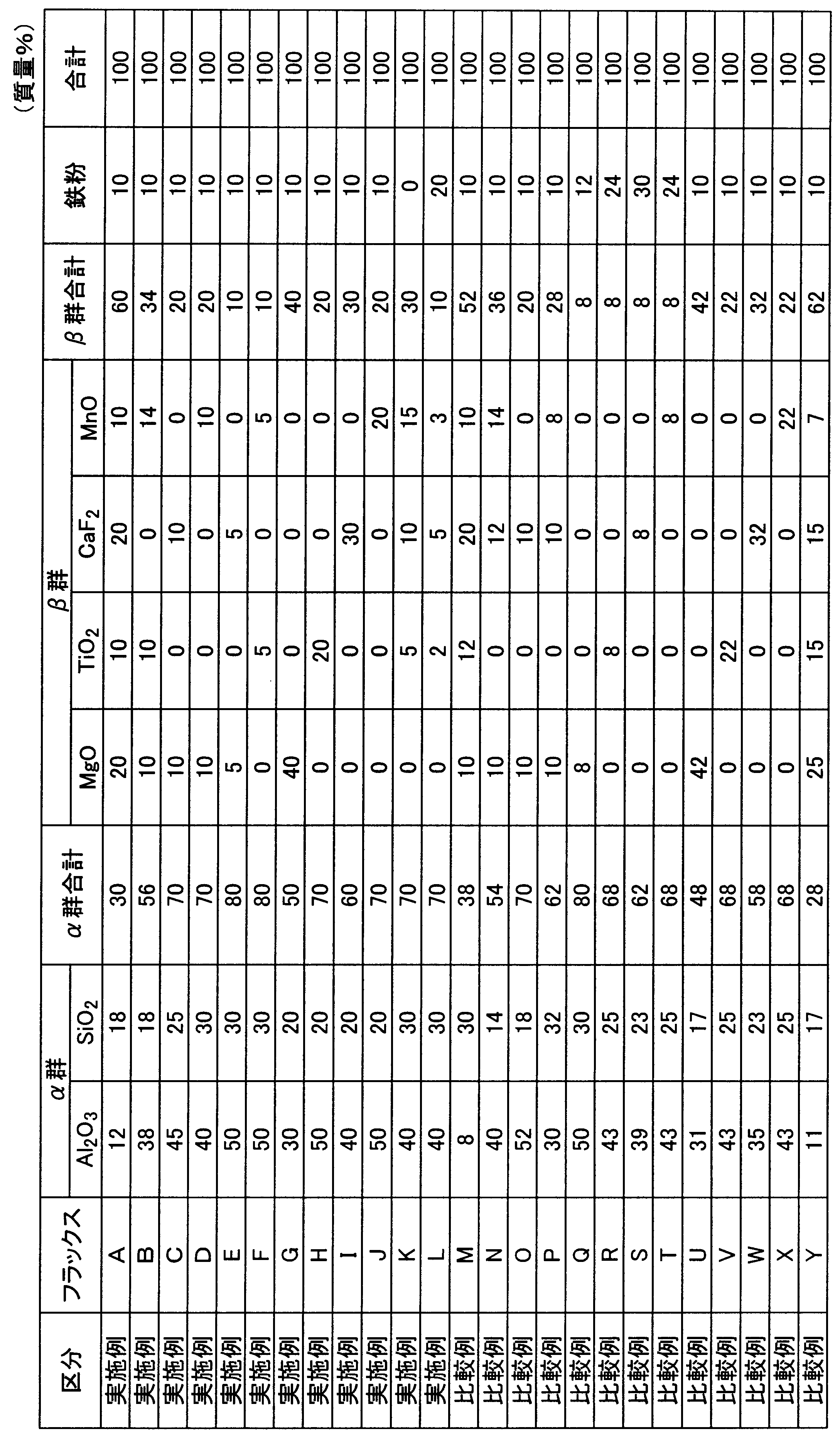
- Table 1 shows the chemical composition of the steel material and the welding wire subjected to the test, and Table 2 shows the composition of the flux. A value of zero in Table 2 indicates that it is not intentionally contained.
- Table 2 shows the composition of the flux. A value of zero in Table 2 indicates that it is not intentionally contained.
- the groove shapes of the pair of steel materials are shown in FIGS. 10 and 14 to 18.
- the welding of the pair of steel materials was performed by 1-pass welding on each surface by submerged arc welding of 2 to 6 electrodes using a welding power source capable of controlling the waveform of the welding current.
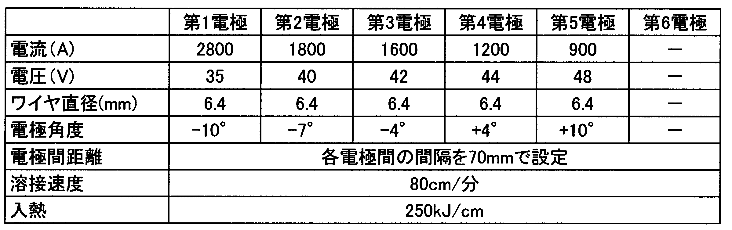
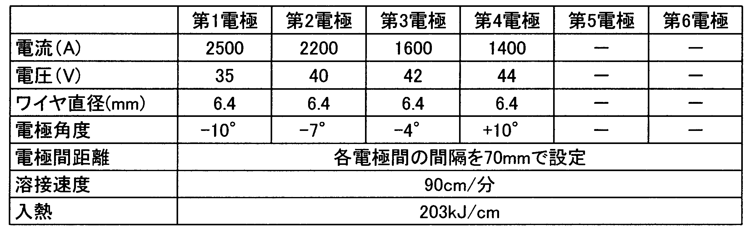
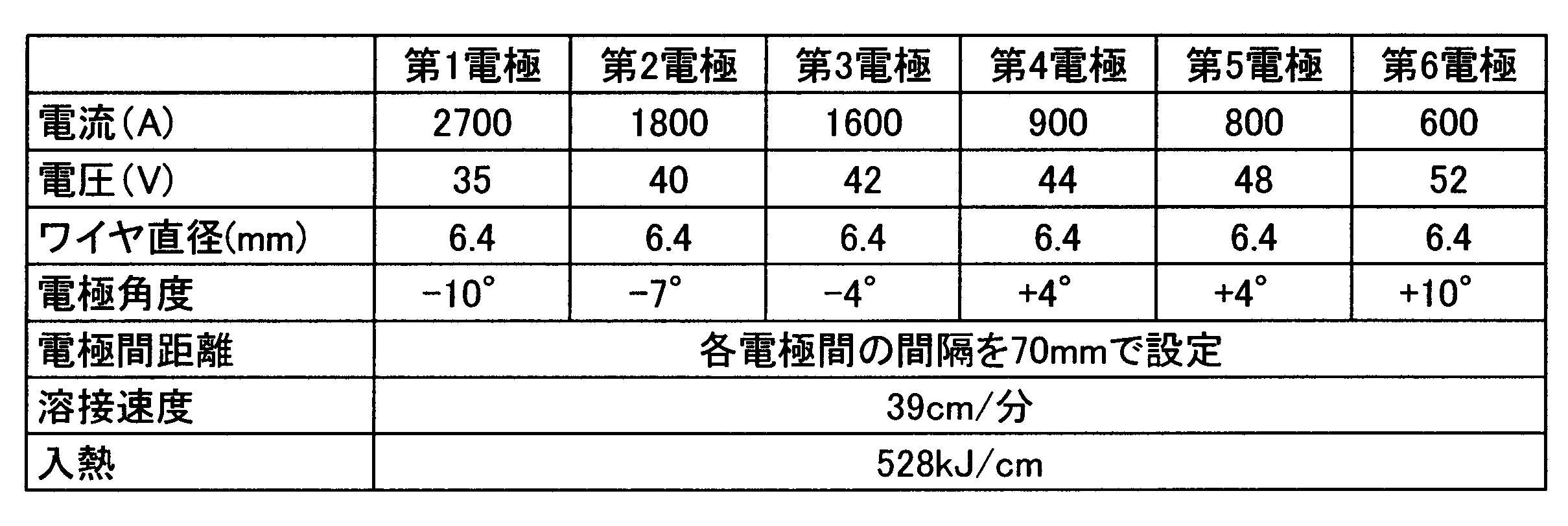
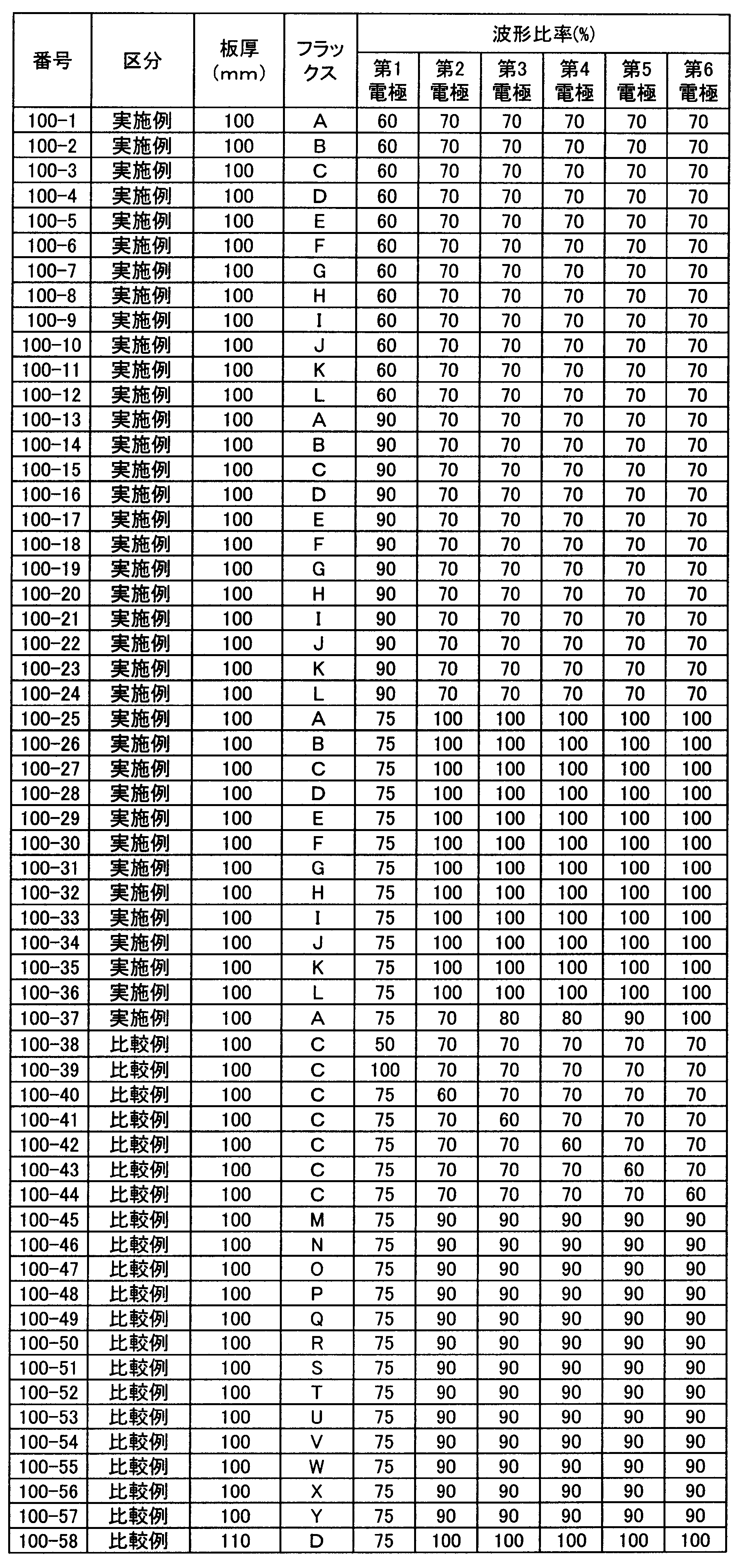
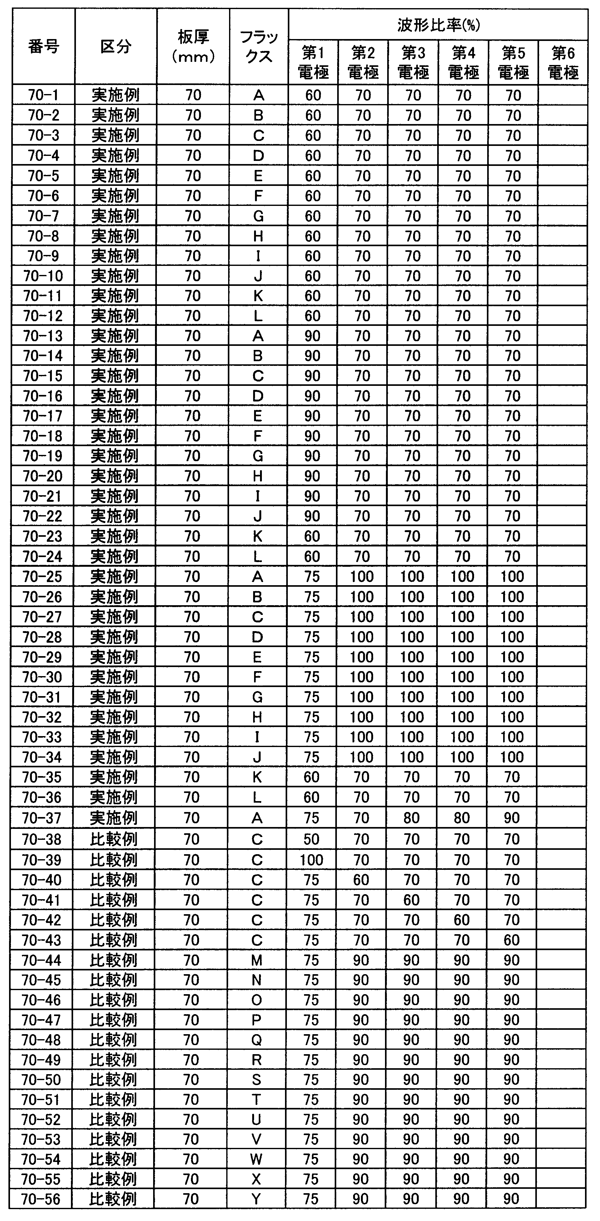
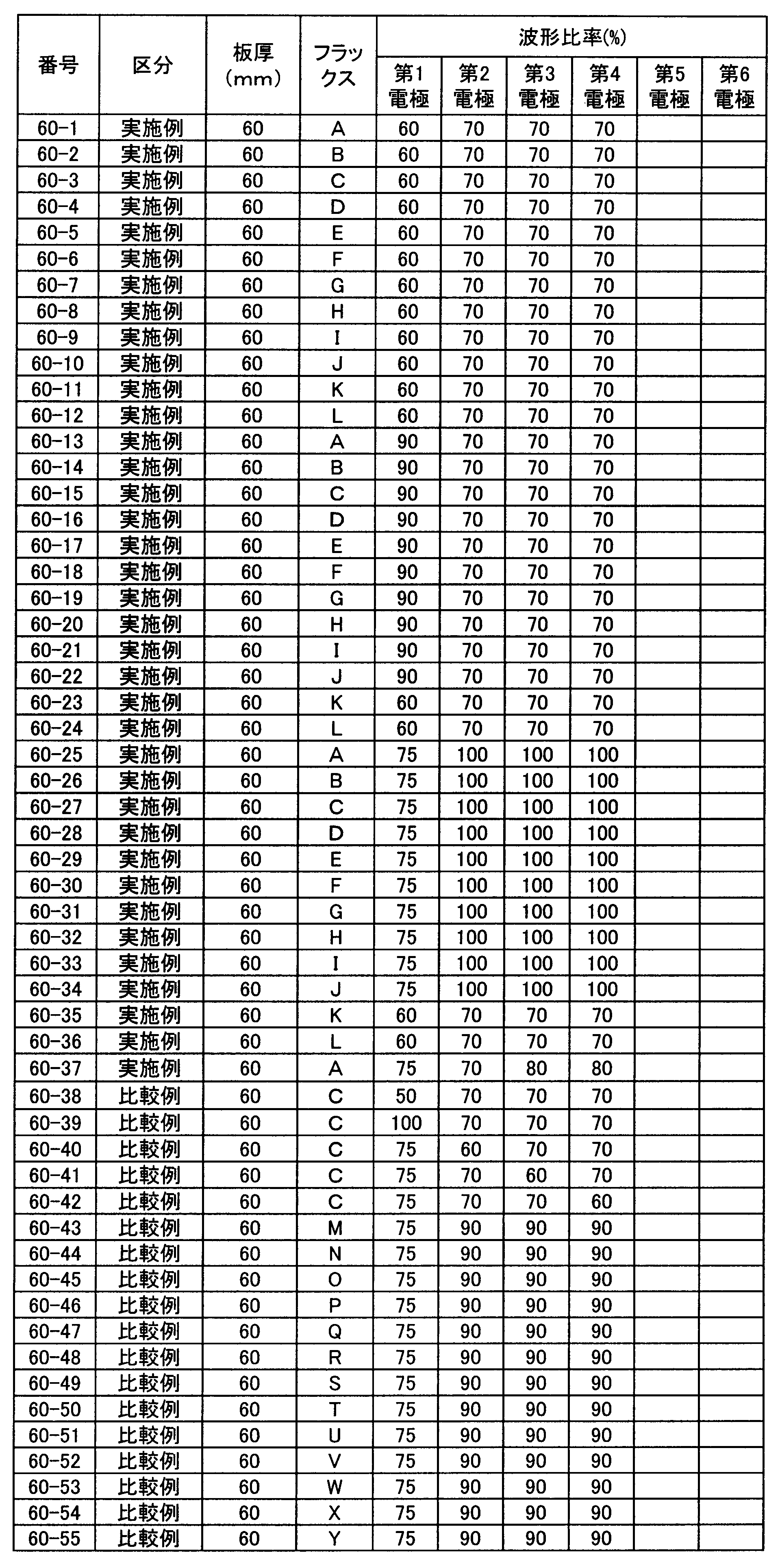
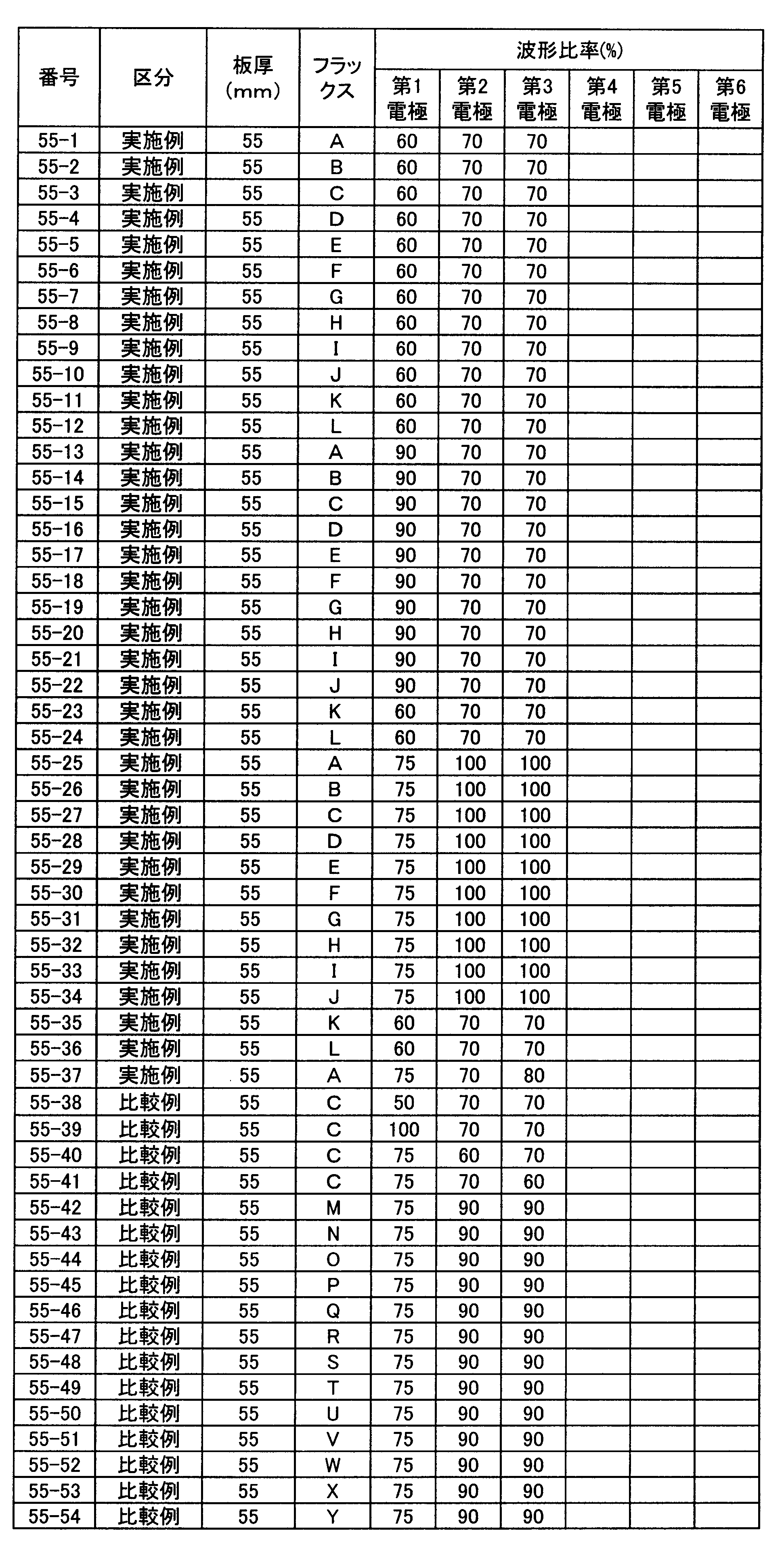
- Tables 3 to 8 show welding conditions other than the waveform ratio, and Tables 9 to 13 show the waveform ratio of the welding current of each electrode 7.
- Table 3 shows the plate thickness of 100 mm and 6 electrode welding conditions
- Table 4 shows the plate thickness of 70 mm and 5 electrode welding conditions
- Table 5 shows the plate thickness of 60 mm and 4 electrode welding conditions
- Table 6 Are the plate thickness of 55 mm and 3 electrode welding conditions
- Table 7 is the plate thickness of 51 mm and 2 electrode welding conditions
- Table 8 is the plate thickness of 110 mm and 6 electrode welding conditions.
- Each electrode 7 was disposed at the center of the groove width.
- the produced weld metal 8 was cut out from the position shown in FIG. 19, and was cut into a component analysis sample, a JIS Z3111 A1 round bar tensile test piece (diameter: 12.5 mm, distance between gauge points (GL): 50 mm) and A V-notch test piece (10 mm full-size test piece) of JIS Z2242 was processed and used for the test.
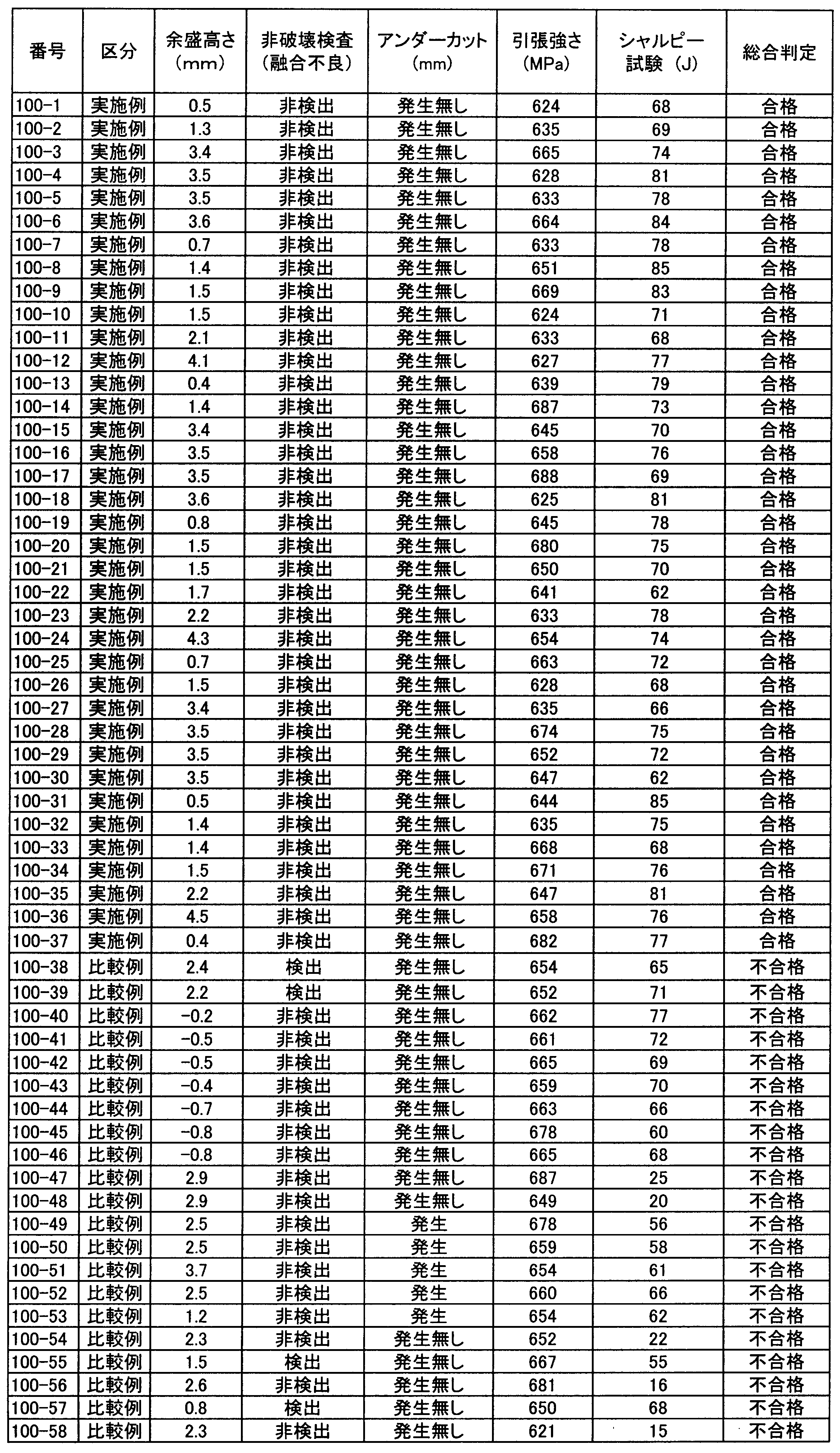
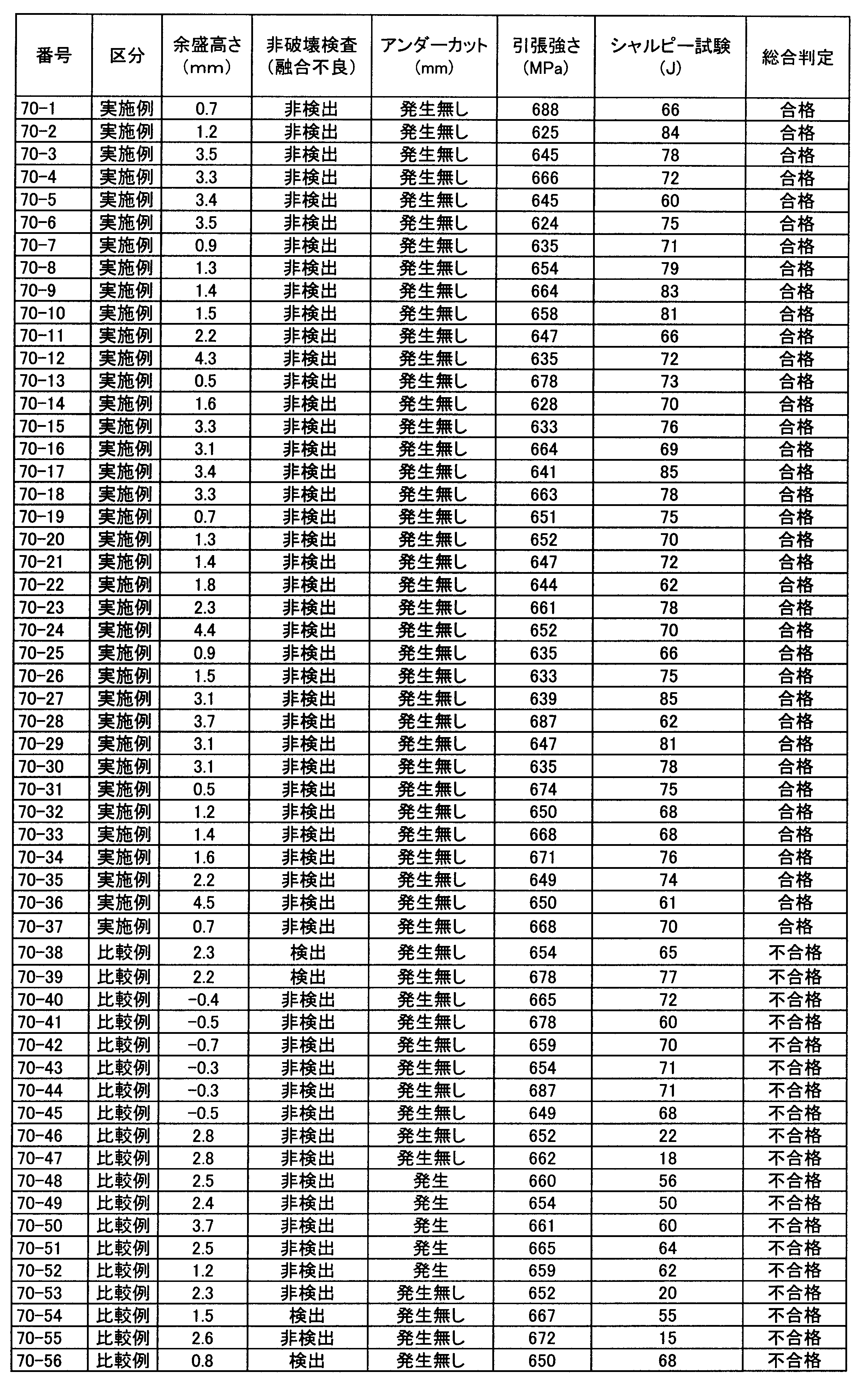
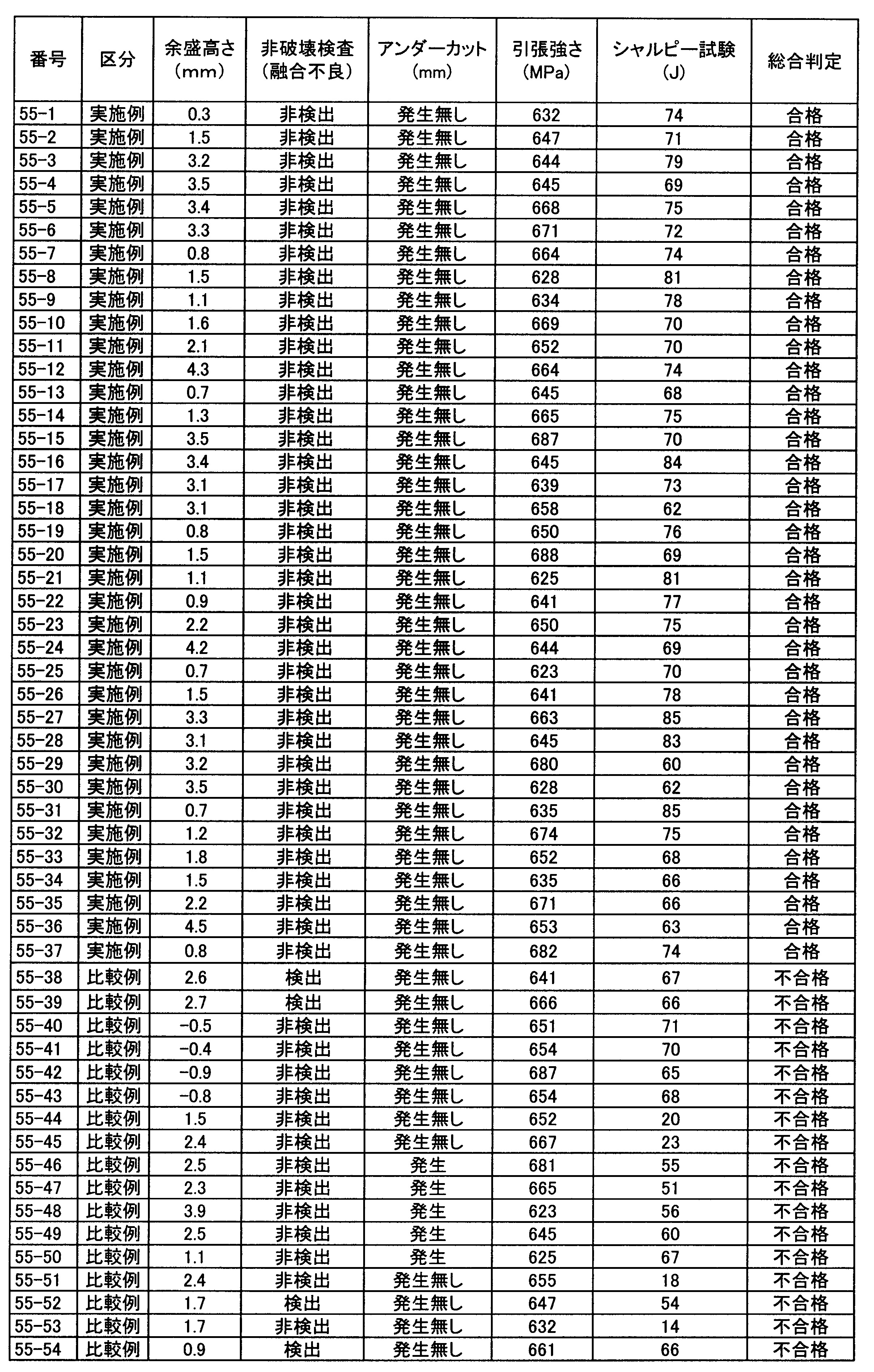
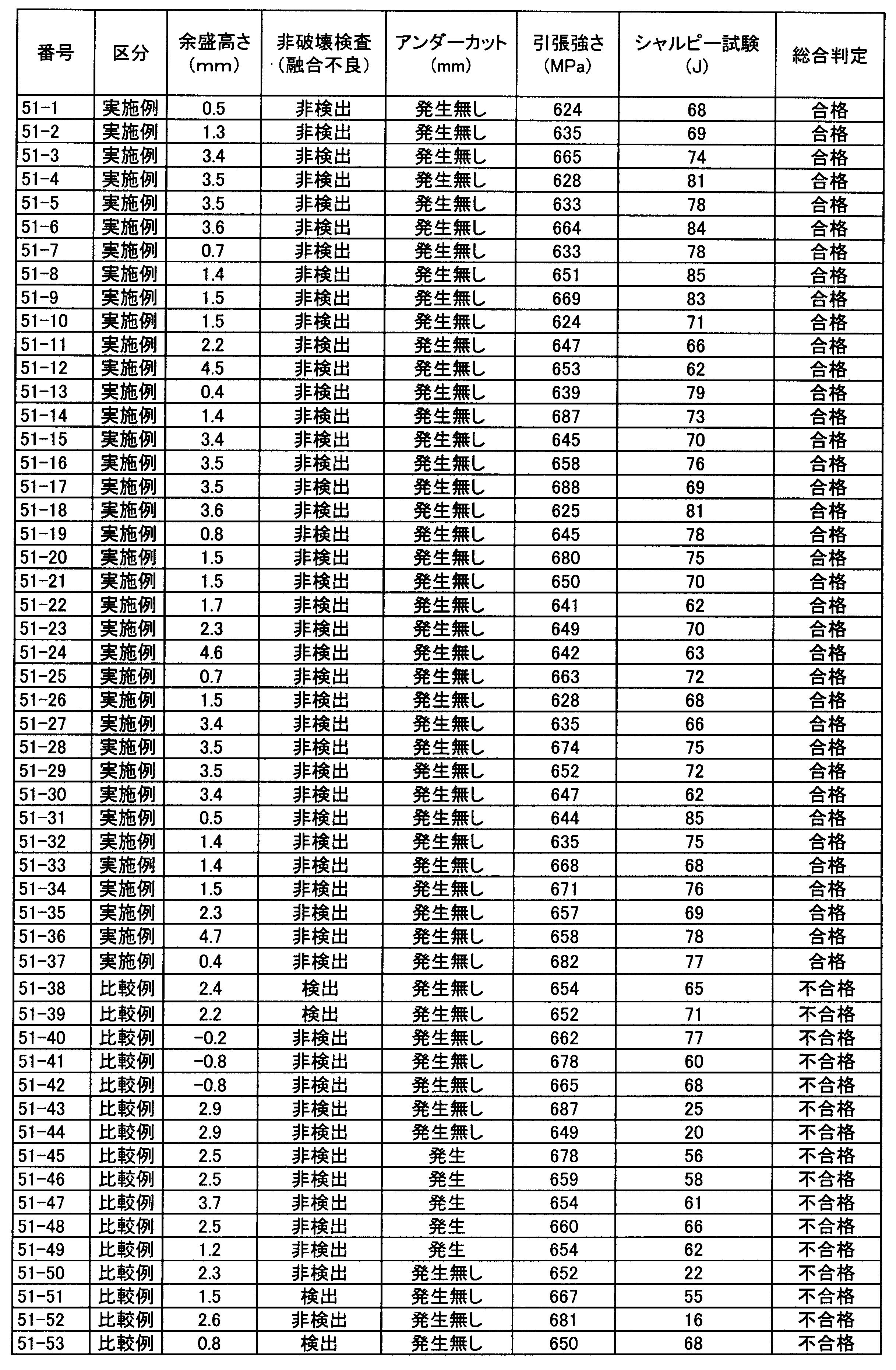
- Tables 15 to 19 show the results of determining these based on the pass / fail criteria in Table 14.
- the Charpy impact test temperature was ⁇ 40 ° C.
- Test numbers 100-1 to 100-37, Test numbers 70-1 to 70-37, Test numbers 60-1 to 60-37, Test numbers 55-1 to 55-37, Test numbers No. 51-1 to No. 51-37 are examples of the present invention, so that the height of the bead is appropriate, there is no poor fusion, no undercut occurs, and the weld metal 8 Good results were also obtained in strength and toughness.
- Al 2 O 3 is 38% and SiO 2 is 22% or more.
- the extra height was 4 mm or more, and a higher effect of increasing the welding amount was recognized.
- test numbers 100-38, 70-38, 60-38, 55-38, 51-38 the waveform ratio of the welding current of the first electrode 1 is 50%, which is outside the scope of the present invention. Therefore, the width of the penetration shape of the weld metal 8 was narrowed, resulting in failure of fusion as shown in FIG. 6A.
- test numbers 100-39, 70-39, 60-39, 55-39, and 51-39 a negative arc with a waveform ratio of 100% was used as the welding current for the first electrode 1, so that no arc occurred. A stable and proper weld metal 8 penetration depth could not be obtained, resulting in poor fusion, which was rejected.
- No. 40 since there was an electrode 7 that deviated from the present invention with a welding current waveform ratio of 60% after the second electrode 2, the required welding amount could not be obtained, and the surplus height became negative. It was not possible to deposit the weld metal up to the surface of 9 and it was rejected.
- Test Nos. 100-53, 70-52, 60-51, 55-50, and Test Nos. 51-49 were excessively deviated from the present invention because the MgO content was excessive. It occurred and was rejected.
- Test No. 100-54, No. 70-53, No. 60-52, No. 55-51, No. 51-50 were the weld metal because the content of TiO 2 was excessive and deviated from the present invention. The toughness of 8 deteriorated and was rejected.
- Test Nos. 100-55, 70-54, 60-53, 55-52, 51-51 were not stable because the CaF 2 content was excessive and deviated from the present invention. In this case, an appropriate penetration depth of the weld metal 8 could not be obtained, resulting in poor fusion, which was rejected.
- the weld metal 8 that can weld the X groove of the thick steel plate with high efficiency and is excellent in toughness even at a low temperature. Can be carried out efficiently and can greatly contribute to the spread of renewable energy.
Landscapes
- Engineering & Computer Science (AREA)
- Chemical & Material Sciences (AREA)
- Mechanical Engineering (AREA)
- Materials Engineering (AREA)
- Metallurgy (AREA)
- Organic Chemistry (AREA)
- Inorganic Chemistry (AREA)
- Physics & Mathematics (AREA)
- Plasma & Fusion (AREA)
- Nonmetallic Welding Materials (AREA)
- Arc Welding In General (AREA)
- Wind Motors (AREA)
- Butt Welding And Welding Of Specific Article (AREA)
Abstract
Description
本願は、2011年11月15日に、日本に出願された特願2011-249928号に基づき優先権を主張し、その内容をここに援用する。
風力発電が今後広く普及するか否かは、経済合理性が重要である。この観点から、風力発電の基礎部における施工コスト削減も重要な課題であり、溶接の分野でもそのような厚鋼板を高能率で溶接施工することが求められている。
このため、上述の社会的ニーズを満足するために、50mm超の厚鋼板を大入熱溶接しても、寒冷地での稼働にも耐え得る靭性の優れた溶接金属が得られるような溶接技術が必要となる。
例えば、特許文献1において、70mm厚の厚鋼板を片面1層で溶接できるサブマージアーク溶接方法が開示されている。
しかしながら、この方法は片面溶接であるため、開先断面積が非常に広く、780kJ/cmと溶接入熱も非常に高い。特許文献1で、溶接金属の靭性は開示されていないが、建築用途であることを考えれば0℃での靭性に対応するものと考えられ、寒冷地での使用に適さないと推測される。
特許文献2においても、建築はボックス柱を対象として大入熱サブマージアーク溶接が行われている。しかし、溶接金属のシャルピー試験は-5℃で評価されているにすぎず、しかも、特許文献1と同様に片面溶接であるため入熱が過大となるものと推測される。
このようなX開先を用いた両面1層溶接方法に関する技術としては、次のようなものが知られている。
また、特許文献4では50mmの板厚が両面1層溶接で検討されている。しかし、風力発電では50mm超の板厚も検討されており、特許文献4も不十分な知見である。
特許文献5においては、30mm以上の板厚を両面1層溶接できる技術を開示するとしている。しかし、実際に実施例で検討されているのは31.8mmまでの知見であり、風力発電の分野に適用できる知見ではない。
なお、ここでは大型構造物を想定しているため、電子ビーム溶接は真空チャンバー容積の観点から対象外としている。
しかし、最近、サブマージアーク溶接の分野でも、特許文献6に示されるような、溶接電流の波形制御を駆使することで、同一溶接電流でも溶着量(ワイヤ送給速度)を増加させることが可能な大容量デジタル制御交流/直流溶接電源が開発され、そのような電源を用いてサブマージアーク溶接する技術が開発された。
この溶接電源では、電流波形の大きさa、bと幅(周期)c、dの4つのパラメータを自由に変更できるようになっており、プラス部分とマイナス部分の大きさを変更することにより、溶け込み深さあるいは溶着量を調整することができる。
上述のような電源を用いて、溶接電流波形を制御した知見としては、例えば特許文献7を挙げることができる。特許文献7において、多層盛り溶接を前提とした1層1パス溶接を開示している。しかし、大入熱溶接によって極厚鋼板を高能率施工する溶接方法ではなく、特許文献7から風力発電のような極厚鋼板の溶接能率を抜本的に改善できる知見は得られない。
更に、板厚が50mmを超えるような厚鋼材のX開先を、出力波形の制御できる溶接電源を用いて、多電極サブマージアーク溶接によってそれぞれの開先を1層のみで1パスつまり片面を1パスで溶接する場合、ワイヤ送給速度を向上させて入熱量を抑制する観点から、どのような溶材や溶接条件を用いるのが好ましいかについては知られていない。
その過程で、特に、フラックスの組成及び第1電極及び、第2電極以降に印加する溶接電流の波形に着目して検討を進めた結果、それらの最適な組み合わせによって上記課題を達成できることを見出した。
(1)本発明の第一の態様に係るサブマージアーク溶接方法は、板厚が50mm超、100mm以下の一対の鋼材に、X開先を加工する加工工程と;前記一対の鋼材に対し、2電極以上、6電極以下の多電極サブマージアーク溶接で、フラックスを用いて表裏面からそれぞれ1パスの溶接を実施する溶接工程と;を備え、前記溶接工程に於いて、第1電極の溶接電流を、波形比率が60%以上、90%以下の交流電流とし、その他の電極の溶接電流を、波形比率が70%以上の交流電流あるいは、マイナスの直流電流として溶接し、前記フラックスが、前記フラックスの全質量に対する質量比で、Al2O3:10%以上、50%以下、SiO2:16%以上、30%以下を含有し、更に、MgO、TiO2、CaF2、MnOの内の1種以上を合計で10%以上、60%以下を含有し、前記MgOを40%以下に制限し、前記TiO2を20%以下に制限し、前記CaF2を30%以下に制限し、前記MnOを20%以下に制限する。
本発明者らはフラックスの成分に関して、次のような実験的な検討を行った。
SAW用フラックスは、酸化物や弗化物などの各種の物質を配合して形成される。そのようなフラックス成分のうち、ワイヤ送給速度を上昇させるためにはどの物質が最も効果的かを調べるため、各物質単独で構成されたフラックスを実験に供して、そのワイヤ送給速度に対する影響を調査した。
サブマージアーク溶接は、図2に示すような矩形波交流溶接電流を用いて行った。その結果を図1に示す。なお、図1で使用している波形比率とは、式1及び図2に示すように交流電流のプラスとマイナスの面積比率であり、プラスの面積をP、マイナスの面積をNとしたとき、N/(N+P)で表される数値を%に換算したものである。波形比率0%は直流プラスを、波形比率100%は直流マイナスを意味している。
波形比率=面積N/(面積N+面積P)・・・・・・式(1)
必須物質であるAl2O3、SiO2の含有量は、フラックス全質量に対する質量%(以下、フラックスの成分は全てフラックス全質量に対する質量%で表記する。)で、Al2O3を10%以上、50%以下、SiO2を16%以上、30%以下とした。
これらの物質はAl2O3やSiO2と比較すると、ワイヤ送給速度向上の効果は少ないが、ZrO2のように波形比率を高めた場合にワイヤ送給速度を減少させる悪影響はなく、スラグの流動性や粘性を適正化する観点から適量含有させることが必要である。このスラグの流動性や粘性を適正化する観点から、これら選択物質の合計量の下限を13%、15%又は20%としてよく、その合計量の上限を55%、50%又は45%としてもよい。
例えば、溶接金属8の成分調整を目的として、フラックス中にSi、Mn、Al、Ti、Mo、Cu、Ni、Cr、V等の金属粉が含有される場合がある。これらの含有量は、上述の特許文献等を参考に適宜調整することができる。また、溶着量の増大とアーク安定を目的として、フラックス中に鉄粉を含有することも可能である。その場合の鉄粉の含有量は10%以上、40%以下とすることが好ましい。大量に添加するとアークが不安定となり易くアークが溶接中に途切れやすくなるために、その含有量の上限を、必要に応じて30%、20%又は15%以下としてもよい。
特許文献6に記載されているような、大容量デジタル制御交流/直流溶接電源を用いて、多電極でサブマージアーク溶接(SAW)を行う場合に、各電極7の溶接電流波形は独立して制御することができる。しかし、多電極による一パス溶接では、第1電極1による溶け込みが重要であるので、第1電極1の電流条件について検討した。
これを更に詳細に検証したデータを図7から図9に示す。図10の開先に第1電極1の条件を2500A、35Vとし、第2電極2以降を1500A、40V、波形比率を90%で固定して、50cm/分の溶接条件でアークを発生させた。第1電極1の波形比率を変えて5mの溶接長を作製し、10cm間隔でマクロ断面を50個切り出して、ルートフェイス(ルート面)部の融合不良の有無を確認した。評価は50個のマクロで1個融合不良があれば1/50で、2%の融合不良発生率として評価した。
図7から図9より、2電極溶接、4電極溶接、6電極溶接のいずれの場合に於いても、第1電極1の波形比率が60%以上、90%以下で、融合不良発生率が抑制されていることが確認された。
また、第2電極2以降は溶接金属8の溶込み形状に大きな影響を及ぼさず、ワイヤ送給速度の向上を考慮すればよいので、第2電極2以降の全電極7で、波形比率が70%以上(波形比率100%の直流マイナスを含む)とする。ワイヤ送給速度の向上のために、その波形比率を75%以上、80%以上又は85%以上としてもよい。なお、溶接に使用する電極数は、生産性(溶接速度)がある程度確保でき、且つ設備構成が過度に複雑となることを避ける観点から2電極以上、6電極以下とする。本願の特徴をより生かすため、電極数を3電極または4電極以上、若しくは鋼材の板厚を55mm以上、60mm以上又は65mm以上としてもよい。
第2電極2以降の波形比率に関して詳細に検討した結果を図11から図13に示す。6電極溶接には図10の開先を、4電極溶接には図14の開先を、2電極溶接には図15の開先を使用した。溶接条件は、第1電極1の条件を2500A、35V、波形比率70%とした。第2電極2以降は、1800A、40Vで、波形比率を変化せた。溶接速度は50cm/分で実施した。上述と同様に波形比率を変えて5mの溶接長を作製し、10cm間隔でマクロ断面を50個切り出して、アンダーフィルの有無を確認した。評価は、アンダーフィルが生じたマクロ試験片の比率で評価した。例えば、50個のマクロで1個アンダーフィルがあれば2%のアンダーフィル発生率として評価した。図11から図13より、波形比率の上昇にしたがってアンダーフィルは減少し、必要な溶着量が入熱を変化させることなく得られることが確認できた。
なお、本発明において、第1電極1から第2電極2以降の各電極7の間隔、配置、角度等について、特に制約を設ける必要はない。前記の溶接試験においては、各電極7の配置は図20に示すように、各電極7の間隔を70mmとし、開先幅の中央部に配置した。第1電極の角度は後退角10°とし、第2電極の角度は後退角7°とし、第3電極の角度は後退角4°とし、第4電極の角度は前進角4°とし、第5電極の角度は前進角7°とし、第6電極(最終極)の角度は前進角10°とした。
板厚50mm超の鋼材の溶接で、特に本発明の効果が発揮されるようになることから、下限を50mm超と定めた。しかし、板厚が100mmを超えるようになると、本発明を適用しても入熱が過大となり必要な靭性が得られないため、100mmを上限とした。
また、開先角度は、入熱抑制の観点から30°以上、50°以下が好ましい。その理由として、角度が30°未満の狭開先では、溶接ビード幅のセンターが外れやすく、また十分な溶込深さを得るのも困難となるからであり、一方、角度が50°を超えると、開先断面積が広くなり溶接入熱が大きくなるため好ましくないからである。
各電極7の角度に関して、第1電極1は溶込みを確保する目的で後退角10°とし、最終極をビード外観確保の観点から前進角10°を採用した。各極間の間隔は溶融金属の溜まり量を適正化するように考慮し、各極70mmの電極間隔を採用した。それぞれの電極7は、開先幅の中央部に配置した。
作製された溶接金属8は図19の位置から断片を切り出し、それを成分分析試料、JIS Z3111のA1号丸棒引張試験片(直径:12.5mm、標点間距離(GL):50mm)およびJIS Z2242のVノッチ試験片(10mmフルサイズ試験片)に加工して試験に供した。これらを表14の合否基準で判定した結果を表15~表19に示す。シャルピー衝撃試験温度は、-40℃とした。
また、試験番号100―11番、100―23番、100―35番、試験番号70―11番、70―23番、70―35番、試験番号60―11番、60―23番、60―35番、試験番号55―11番、55―23番、55―35番、試験番号51―11番、51―23番、51―35番、においては、鉄粉が含有されていないにも関わらず、Al2O3、SiO2の効果により、余盛高さが2mm以上と優れた溶着量増加の効果を発現している。
更に試験番号100―12番、100―24番、100―36番、試験番号70―12番、70―24番、70―36番、試験番号60―12番、60―24番、60―36番、試験番号55―12番、55―24番、55―36番、試験番号51―12番、51―24番、51―36番、においては上記のAl2O3、SiO2の効果に加え、鉄粉の含有量を20%に増加した試験番号では、余盛高さが4mm以上であり、更に高い溶着量増加の効果が認められている。
試験番号100-40番から100-44番、試験番号70-40番から70-43番、試験番号60-40番から60-42番、試験番号55-40から55-41番、試験番号51-40番においては、第2電極2以降に、溶接電流の波形比率が60%という本発明を逸脱した電極7があったため、必要な溶着量が得られず、余盛高さがマイナスとなり鋼板9の表面まで溶着金属を盛ることができず不合格となった。
試験番号100-47番と試験番号100-48番、試験番号70-46番と試験番号70-47番、試験番号60-45番と試験番号60-46番、試験番号55-44番と試験番号55-45番、試験番号51-43番と試験番号51-44番では、Al2O3あるいはSiO2が本発明の上限値を上回って過剰に含有されたため、溶接金属8の靭性が劣化して不合格となった。
試験番号100-49番から100-52番、試験番号70-48番から70-51番、試験番号60-47から60-50番、試験番号55-46番から55-49番、試験番号51-45番から51-48番においては、MgO、TiO2、CaF2、MnOの合計含有量が本発明の下限値である10%に満たないために、アンダーカットが発生し不合格となった。
試験番号100-54番、70-53番、60-52番、試験番号55-51番、51-50番は、TiO2の含有量が本発明を逸脱して過剰であったために、溶接金属8の靭性が劣化して不合格となった。
試験番号100-55番、70-54番、60-53番、55-52番、51-51番は、CaF2の含有量が本発明を逸脱して過剰であったために、アークが不安定で適正な溶接金属8の溶込み深さが得られず、融合不良を発生したため不合格となった。
試験番号100-57番、70-56番、60-55番、55-54番、51-53番は、MgO、TiO2、CaF2、MnOの合計含有量が本発明の上限値である60%を超えて過剰であったために、アークが不安定で適正な溶接金属8の溶込み深さが得られず、融合不良を発生したため不合格となった。
試験番号100-58番は、本発明の範囲を逸脱し、板厚が過剰であったために入熱が多くなり、溶接金属8の靭性が劣化して不合格となった。







2 第2電極
3 第3電極
4 第4電極
5 第5電極
6 第6電極
7 電極
8 溶接金属
9 鋼板
a、b 電流波形の大きさ
c、d 電流波形の幅(周期)
Claims (5)
- 板厚が50mm超、100mm以下の一対の鋼材に、X開先を加工する加工工程と;
前記一対の鋼材に対し、2電極以上、6電極以下の多電極サブマージアーク溶接で、フラックスを用いて表裏面からそれぞれ1パスの溶接を実施する溶接工程と;
を備え、
前記溶接工程に於いて、第1電極の溶接電流を、波形比率が60%以上、90%以下の交流電流とし、その他の電極の溶接電流を、波形比率が70%以上の交流電流あるいは、マイナスの直流電流として溶接し、
前記フラックスが、前記フラックスの全質量に対する質量比で、
Al2O3:10%以上、50%以下、
SiO2:16%以上、30%以下
を含有し、
更に、MgO、TiO2、CaF2、MnOの内の1種以上を合計で10%以上、60%以下を含有し、
前記MgOを40%以下に制限し、前記TiO2を20%以下に制限し、前記CaF2を30%以下に制限し、前記MnOを20%以下に制限する
ことを特徴とするサブマージアーク溶接方法。 - 前記第1電極の前記溶接電流が2500A以上であることを特徴とする請求項1に記載のサブマージアーク溶接方法。
- 前記一対の鋼材間に複数形成される開先形状として、ルートフェイスの高さは5mm以上、前記板厚の25%以下であることを特徴とする請求項1又は2に記載のサブマージアーク溶接方法。
- 前記X開先の開先角度が、30°以上、50°以下であることを特徴とする請求項3に記載のサブマージアーク溶接方法。
- 前記X開先の開先角度が、30°以上、50°以下であることを特徴とする請求項1又は2に記載のサブマージアーク溶接方法。
Priority Applications (6)
| Application Number | Priority Date | Filing Date | Title |
|---|---|---|---|
| JP2013513458A JP5403186B2 (ja) | 2011-11-15 | 2012-11-14 | 厚鋼板の高能率溶接方法 |
| ES12849423.4T ES2619031T3 (es) | 2011-11-15 | 2012-11-14 | Método de soldadura de alta eficiencia de placas de acero gruesas |
| EP12849423.4A EP2767361B1 (en) | 2011-11-15 | 2012-11-14 | Method for high-efficiency welding of thick steel plates |
| DK12849423.4T DK2767361T3 (en) | 2011-11-15 | 2012-11-14 | PROCEDURE FOR HIGH-EFFICIENCY WELDING OF THICK STEEL STEPS |
| CN201280055656.2A CN103945973B (zh) | 2011-11-15 | 2012-11-14 | 厚钢板的高效率焊接方法 |
| KR1020147012385A KR101472722B1 (ko) | 2011-11-15 | 2012-11-14 | 후강판의 고능률 용접 방법 |
Applications Claiming Priority (2)
| Application Number | Priority Date | Filing Date | Title |
|---|---|---|---|
| JP2011249928 | 2011-11-15 | ||
| JP2011-249928 | 2011-11-15 |
Publications (1)
| Publication Number | Publication Date |
|---|---|
| WO2013073565A1 true WO2013073565A1 (ja) | 2013-05-23 |
Family
ID=48429621
Family Applications (1)
| Application Number | Title | Priority Date | Filing Date |
|---|---|---|---|
| PCT/JP2012/079492 Ceased WO2013073565A1 (ja) | 2011-11-15 | 2012-11-14 | 厚鋼板の高能率溶接方法 |
Country Status (7)
| Country | Link |
|---|---|
| EP (1) | EP2767361B1 (ja) |
| JP (1) | JP5403186B2 (ja) |
| KR (1) | KR101472722B1 (ja) |
| CN (1) | CN103945973B (ja) |
| DK (1) | DK2767361T3 (ja) |
| ES (1) | ES2619031T3 (ja) |
| WO (1) | WO2013073565A1 (ja) |
Cited By (6)
| Publication number | Priority date | Publication date | Assignee | Title |
|---|---|---|---|---|
| CN107553008A (zh) * | 2017-10-30 | 2018-01-09 | 巩义市广大焊业有限责任公司 | 一种x70管线钢直缝埋弧焊用焊剂及其制备方法 |
| JP2021167025A (ja) * | 2016-06-28 | 2021-10-21 | リンカーン グローバル,インコーポレイテッド | ステンレス鋼用途のための溶接波形 |
| WO2024166791A1 (ja) | 2023-02-06 | 2024-08-15 | Jfeスチール株式会社 | 鋼板の溶接継手およびその製造方法 |
| WO2024166790A1 (ja) | 2023-02-06 | 2024-08-15 | Jfeスチール株式会社 | 鋼板の溶接継手およびその製造方法 |
| KR20250145123A (ko) | 2023-03-31 | 2025-10-13 | 제이에프이 스틸 가부시키가이샤 | 강판의 가스 실드 아크 용접에 의한 용접 조인트의 제조 방법 |
| KR20250150127A (ko) | 2023-03-31 | 2025-10-17 | 제이에프이 스틸 가부시키가이샤 | 강판의 가스 실드 아크 용접에 의한 용접 조인트의 제조 방법 |
Families Citing this family (4)
| Publication number | Priority date | Publication date | Assignee | Title |
|---|---|---|---|---|
| KR101696025B1 (ko) * | 2014-08-21 | 2017-01-13 | 주식회사 포스코 | 충격인성이 우수한 용접이음부 및 그 제조 방법 |
| JP6383319B2 (ja) * | 2015-03-31 | 2018-08-29 | 株式会社神戸製鋼所 | 多電極片面1層サブマージアーク溶接方法 |
| CN104923892B (zh) * | 2015-06-12 | 2017-05-10 | 中石化石油工程机械有限公司沙市钢管厂 | 优化设计管线钢埋弧焊工艺参数的方法 |
| KR101898159B1 (ko) | 2016-06-21 | 2018-09-14 | 주식회사 포스코 | 용접 생산성 및 용접부 저온인성이 우수한 극후물 강판 용접이음부의 제조방법 |
Citations (10)
| Publication number | Priority date | Publication date | Assignee | Title |
|---|---|---|---|---|
| JPS6245475A (ja) * | 1985-08-24 | 1987-02-27 | Nippon Steel Corp | 厚板の両面1層サブマ−ジア−ク溶接法 |
| JPH0673757B2 (ja) * | 1988-12-28 | 1994-09-21 | 川崎製鉄株式会社 | 厚鋼板の大入熱潜弧溶接方法 |
| JPH09206946A (ja) | 1996-02-05 | 1997-08-12 | Nippon Steel Weld Prod & Eng Co Ltd | 3電極サブマージアーク溶接方法 |
| JPH09277083A (ja) | 1996-04-16 | 1997-10-28 | Nippon Steel Corp | 大入熱用耐候性鋼サブマージアーク溶接方法 |
| JP2004143556A (ja) | 2002-10-25 | 2004-05-20 | Jfe Steel Kk | 厳格靭性要求を満たす厚肉大径ストレートuoe鋼管およびその製造方法 |
| JP2005193299A (ja) | 2003-12-15 | 2005-07-21 | Lincoln Global Inc | 電気アーク溶接システム |
| JP2006007313A (ja) * | 2004-06-22 | 2006-01-12 | Lincoln Global Inc | 高電流溶接用電源 |
| JP2009195957A (ja) | 2008-02-22 | 2009-09-03 | Jfe Steel Corp | 鋼材の多電極サブマージアーク溶接方法 |
| JP2009241128A (ja) | 2008-03-31 | 2009-10-22 | Jfe Steel Corp | 溶接鋼管の製造方法 |
| JP2011200920A (ja) | 2010-03-26 | 2011-10-13 | Ihi Corp | サブマージアーク溶接方法及び装置 |
Family Cites Families (4)
| Publication number | Priority date | Publication date | Assignee | Title |
|---|---|---|---|---|
| US5004884A (en) * | 1988-12-28 | 1991-04-02 | Kawasaki Steel Corporation | Method of submerged arc welding a thick steel plate with large heat input and submerged arc welding flux |
| JP2000042741A (ja) * | 1998-07-30 | 2000-02-15 | Nkk Corp | 極厚鋼板のサブマージアーク溶接方法 |
| EP2255915B1 (en) * | 2008-02-22 | 2018-04-11 | JFE Steel Corporation | Submerged arc welding method with multiple electrodes for steel material |
| JP5489274B2 (ja) * | 2010-02-22 | 2014-05-14 | 株式会社神戸製鋼所 | 多電極片面溶接装置のアークスタート方法および多電極片面溶接装置 |
-
2012
- 2012-11-14 ES ES12849423.4T patent/ES2619031T3/es active Active
- 2012-11-14 CN CN201280055656.2A patent/CN103945973B/zh active Active
- 2012-11-14 WO PCT/JP2012/079492 patent/WO2013073565A1/ja not_active Ceased
- 2012-11-14 JP JP2013513458A patent/JP5403186B2/ja active Active
- 2012-11-14 DK DK12849423.4T patent/DK2767361T3/en active
- 2012-11-14 KR KR1020147012385A patent/KR101472722B1/ko active Active
- 2012-11-14 EP EP12849423.4A patent/EP2767361B1/en active Active
Patent Citations (10)
| Publication number | Priority date | Publication date | Assignee | Title |
|---|---|---|---|---|
| JPS6245475A (ja) * | 1985-08-24 | 1987-02-27 | Nippon Steel Corp | 厚板の両面1層サブマ−ジア−ク溶接法 |
| JPH0673757B2 (ja) * | 1988-12-28 | 1994-09-21 | 川崎製鉄株式会社 | 厚鋼板の大入熱潜弧溶接方法 |
| JPH09206946A (ja) | 1996-02-05 | 1997-08-12 | Nippon Steel Weld Prod & Eng Co Ltd | 3電極サブマージアーク溶接方法 |
| JPH09277083A (ja) | 1996-04-16 | 1997-10-28 | Nippon Steel Corp | 大入熱用耐候性鋼サブマージアーク溶接方法 |
| JP2004143556A (ja) | 2002-10-25 | 2004-05-20 | Jfe Steel Kk | 厳格靭性要求を満たす厚肉大径ストレートuoe鋼管およびその製造方法 |
| JP2005193299A (ja) | 2003-12-15 | 2005-07-21 | Lincoln Global Inc | 電気アーク溶接システム |
| JP2006007313A (ja) * | 2004-06-22 | 2006-01-12 | Lincoln Global Inc | 高電流溶接用電源 |
| JP2009195957A (ja) | 2008-02-22 | 2009-09-03 | Jfe Steel Corp | 鋼材の多電極サブマージアーク溶接方法 |
| JP2009241128A (ja) | 2008-03-31 | 2009-10-22 | Jfe Steel Corp | 溶接鋼管の製造方法 |
| JP2011200920A (ja) | 2010-03-26 | 2011-10-13 | Ihi Corp | サブマージアーク溶接方法及び装置 |
Non-Patent Citations (1)
| Title |
|---|
| See also references of EP2767361A4 |
Cited By (11)
| Publication number | Priority date | Publication date | Assignee | Title |
|---|---|---|---|---|
| JP2021167025A (ja) * | 2016-06-28 | 2021-10-21 | リンカーン グローバル,インコーポレイテッド | ステンレス鋼用途のための溶接波形 |
| CN107553008A (zh) * | 2017-10-30 | 2018-01-09 | 巩义市广大焊业有限责任公司 | 一种x70管线钢直缝埋弧焊用焊剂及其制备方法 |
| WO2024166791A1 (ja) | 2023-02-06 | 2024-08-15 | Jfeスチール株式会社 | 鋼板の溶接継手およびその製造方法 |
| WO2024166790A1 (ja) | 2023-02-06 | 2024-08-15 | Jfeスチール株式会社 | 鋼板の溶接継手およびその製造方法 |
| KR20250132509A (ko) | 2023-02-06 | 2025-09-04 | 제이에프이 스틸 가부시키가이샤 | 강판의 용접 이음매 및 그 제조 방법 |
| KR20250132508A (ko) | 2023-02-06 | 2025-09-04 | 제이에프이 스틸 가부시키가이샤 | 강판의 용접 이음매 및 그 제조 방법 |
| EP4628238A1 (en) | 2023-02-06 | 2025-10-08 | JFE Steel Corporation | Welded joint of steel plate and method for manufacturing same |
| KR20250145123A (ko) | 2023-03-31 | 2025-10-13 | 제이에프이 스틸 가부시키가이샤 | 강판의 가스 실드 아크 용접에 의한 용접 조인트의 제조 방법 |
| KR20250150127A (ko) | 2023-03-31 | 2025-10-17 | 제이에프이 스틸 가부시키가이샤 | 강판의 가스 실드 아크 용접에 의한 용접 조인트의 제조 방법 |
| EP4656318A1 (en) | 2023-03-31 | 2025-12-03 | JFE Steel Corporation | Method for manufacturing welded joint through gas-shielded arc welding of steel plate |
| EP4656319A1 (en) | 2023-03-31 | 2025-12-03 | JFE Steel Corporation | Production method for welded joint by gas-shielded arc welding of steel plate |
Also Published As
| Publication number | Publication date |
|---|---|
| EP2767361B1 (en) | 2017-01-04 |
| CN103945973A (zh) | 2014-07-23 |
| ES2619031T3 (es) | 2017-06-22 |
| EP2767361A4 (en) | 2015-09-23 |
| KR101472722B1 (ko) | 2014-12-12 |
| KR20140065481A (ko) | 2014-05-29 |
| JP5403186B2 (ja) | 2014-01-29 |
| DK2767361T3 (en) | 2017-03-13 |
| JPWO2013073565A1 (ja) | 2015-04-02 |
| EP2767361A1 (en) | 2014-08-20 |
| CN103945973B (zh) | 2015-07-01 |
Similar Documents
| Publication | Publication Date | Title |
|---|---|---|
| JP5403186B2 (ja) | 厚鋼板の高能率溶接方法 | |
| JP5521632B2 (ja) | 厚鋼板の溶接方法 | |
| JP6766866B2 (ja) | フラックス入りワイヤ、溶接継手の製造方法、及び溶接継手 | |
| US20120024822A1 (en) | Combination welding method using combination of gas metal arc welding and submerged-arc welding and combination arc welding machine | |
| CN102744498A (zh) | 一种特厚高强桥梁钢板焊接方法 | |
| KR20080030936A (ko) | 고장력강용 가스 실드 아크 용접 플럭스 함유 와이어 | |
| CN1608791A (zh) | 埋弧焊用熔融焊剂 | |
| RU2014117665A (ru) | Сварная стальная труба с превосходной ударной вязкостью околошовной зоны и способ ее производства | |
| US9981350B2 (en) | Welding flux used for austenitic stainless steel | |
| JP2013154363A (ja) | 片面サブマージアーク溶接用フラックス | |
| JPWO2013179614A1 (ja) | レーザ・アークハイブリッド溶接方法 | |
| WO2009104806A1 (ja) | 鋼材の多電極サブマージアーク溶接方法 | |
| JP5854145B2 (ja) | サブマージアーク溶接方法ならびに溶接継手および鋼管の製造方法 | |
| JP6209135B2 (ja) | 狭開先タンデムサブマージアーク溶接方法 | |
| JP2009214127A (ja) | 鋼材のサブマージアーク溶接方法 | |
| JP2009233679A (ja) | 鋼材のサブマージアーク溶接方法 | |
| EP3162489B1 (en) | Method of butt welding steel plates and butt weld joint of steel plates | |
| KR100709521B1 (ko) | 대입열용접의 용접이음매 및 그 용접방법 | |
| JP2018192518A (ja) | ガスシールドアーク溶接用フラックス入りワイヤ、及び溶接継手の製造方法 | |
| JP2020015092A (ja) | 2相ステンレス鋼溶接用フラックス入りワイヤ、溶接方法および溶接金属 | |
| JP6515287B2 (ja) | 溶接継手の製造方法 | |
| JP2015205303A (ja) | ガスシールドアーク溶接用フラックス入りワイヤ | |
| JP2013081985A (ja) | 鋼材のサブマージアーク溶接方法 | |
| JP7423395B2 (ja) | オーステナイト系ステンレス鋼溶接継手の製造方法 | |
| JP5954272B2 (ja) | サブマージアーク溶接方法および溶接継手の製造方法 |
Legal Events
| Date | Code | Title | Description |
|---|---|---|---|
| ENP | Entry into the national phase |
Ref document number: 2013513458 Country of ref document: JP Kind code of ref document: A |
|
| 121 | Ep: the epo has been informed by wipo that ep was designated in this application |
Ref document number: 12849423 Country of ref document: EP Kind code of ref document: A1 |
|
| REEP | Request for entry into the european phase |
Ref document number: 2012849423 Country of ref document: EP |
|
| WWE | Wipo information: entry into national phase |
Ref document number: 2012849423 Country of ref document: EP |
|
| ENP | Entry into the national phase |
Ref document number: 20147012385 Country of ref document: KR Kind code of ref document: A |
|
| NENP | Non-entry into the national phase |
Ref country code: DE |