WO2013073484A1 - 電気自動車の充電口構造 - Google Patents
電気自動車の充電口構造 Download PDFInfo
- Publication number
- WO2013073484A1 WO2013073484A1 PCT/JP2012/079183 JP2012079183W WO2013073484A1 WO 2013073484 A1 WO2013073484 A1 WO 2013073484A1 JP 2012079183 W JP2012079183 W JP 2012079183W WO 2013073484 A1 WO2013073484 A1 WO 2013073484A1
- Authority
- WO
- WIPO (PCT)
- Prior art keywords
- charging
- connection connector
- power
- cable
- external connection
- Prior art date
- Legal status (The legal status is an assumption and is not a legal conclusion. Google has not performed a legal analysis and makes no representation as to the accuracy of the status listed.)
- Ceased
Links
Images





Classifications
-
- B—PERFORMING OPERATIONS; TRANSPORTING
- B60—VEHICLES IN GENERAL
- B60L—PROPULSION OF ELECTRICALLY-PROPELLED VEHICLES; SUPPLYING ELECTRIC POWER FOR AUXILIARY EQUIPMENT OF ELECTRICALLY-PROPELLED VEHICLES; ELECTRODYNAMIC BRAKE SYSTEMS FOR VEHICLES IN GENERAL; MAGNETIC SUSPENSION OR LEVITATION FOR VEHICLES; MONITORING OPERATING VARIABLES OF ELECTRICALLY-PROPELLED VEHICLES; ELECTRIC SAFETY DEVICES FOR ELECTRICALLY-PROPELLED VEHICLES
- B60L1/00—Supplying electric power to auxiliary equipment of vehicles
- B60L1/006—Supplying electric power to auxiliary equipment of vehicles to power outlets
-
- B—PERFORMING OPERATIONS; TRANSPORTING
- B60—VEHICLES IN GENERAL
- B60L—PROPULSION OF ELECTRICALLY-PROPELLED VEHICLES; SUPPLYING ELECTRIC POWER FOR AUXILIARY EQUIPMENT OF ELECTRICALLY-PROPELLED VEHICLES; ELECTRODYNAMIC BRAKE SYSTEMS FOR VEHICLES IN GENERAL; MAGNETIC SUSPENSION OR LEVITATION FOR VEHICLES; MONITORING OPERATING VARIABLES OF ELECTRICALLY-PROPELLED VEHICLES; ELECTRIC SAFETY DEVICES FOR ELECTRICALLY-PROPELLED VEHICLES
- B60L3/00—Electric devices on electrically-propelled vehicles for safety purposes; Monitoring operating variables, e.g. speed, deceleration or energy consumption
- B60L3/0023—Detecting, eliminating, remedying or compensating for drive train abnormalities, e.g. failures within the drive train
- B60L3/0061—Detecting, eliminating, remedying or compensating for drive train abnormalities, e.g. failures within the drive train relating to electrical machines
-
- B—PERFORMING OPERATIONS; TRANSPORTING
- B60—VEHICLES IN GENERAL
- B60L—PROPULSION OF ELECTRICALLY-PROPELLED VEHICLES; SUPPLYING ELECTRIC POWER FOR AUXILIARY EQUIPMENT OF ELECTRICALLY-PROPELLED VEHICLES; ELECTRODYNAMIC BRAKE SYSTEMS FOR VEHICLES IN GENERAL; MAGNETIC SUSPENSION OR LEVITATION FOR VEHICLES; MONITORING OPERATING VARIABLES OF ELECTRICALLY-PROPELLED VEHICLES; ELECTRIC SAFETY DEVICES FOR ELECTRICALLY-PROPELLED VEHICLES
- B60L50/00—Electric propulsion with power supplied within the vehicle
- B60L50/50—Electric propulsion with power supplied within the vehicle using propulsion power supplied by batteries or fuel cells
- B60L50/51—Electric propulsion with power supplied within the vehicle using propulsion power supplied by batteries or fuel cells characterised by AC-motors
-
- B—PERFORMING OPERATIONS; TRANSPORTING
- B60—VEHICLES IN GENERAL
- B60L—PROPULSION OF ELECTRICALLY-PROPELLED VEHICLES; SUPPLYING ELECTRIC POWER FOR AUXILIARY EQUIPMENT OF ELECTRICALLY-PROPELLED VEHICLES; ELECTRODYNAMIC BRAKE SYSTEMS FOR VEHICLES IN GENERAL; MAGNETIC SUSPENSION OR LEVITATION FOR VEHICLES; MONITORING OPERATING VARIABLES OF ELECTRICALLY-PROPELLED VEHICLES; ELECTRIC SAFETY DEVICES FOR ELECTRICALLY-PROPELLED VEHICLES
- B60L53/00—Methods of charging batteries, specially adapted for electric vehicles; Charging stations or on-board charging equipment therefor; Exchange of energy storage elements in electric vehicles
- B60L53/10—Methods of charging batteries, specially adapted for electric vehicles; Charging stations or on-board charging equipment therefor; Exchange of energy storage elements in electric vehicles characterised by the energy transfer between the charging station and the vehicle
- B60L53/11—DC charging controlled by the charging station, e.g. mode 4
-
- B—PERFORMING OPERATIONS; TRANSPORTING
- B60—VEHICLES IN GENERAL
- B60L—PROPULSION OF ELECTRICALLY-PROPELLED VEHICLES; SUPPLYING ELECTRIC POWER FOR AUXILIARY EQUIPMENT OF ELECTRICALLY-PROPELLED VEHICLES; ELECTRODYNAMIC BRAKE SYSTEMS FOR VEHICLES IN GENERAL; MAGNETIC SUSPENSION OR LEVITATION FOR VEHICLES; MONITORING OPERATING VARIABLES OF ELECTRICALLY-PROPELLED VEHICLES; ELECTRIC SAFETY DEVICES FOR ELECTRICALLY-PROPELLED VEHICLES
- B60L53/00—Methods of charging batteries, specially adapted for electric vehicles; Charging stations or on-board charging equipment therefor; Exchange of energy storage elements in electric vehicles
- B60L53/10—Methods of charging batteries, specially adapted for electric vehicles; Charging stations or on-board charging equipment therefor; Exchange of energy storage elements in electric vehicles characterised by the energy transfer between the charging station and the vehicle
- B60L53/14—Conductive energy transfer
- B60L53/16—Connectors, e.g. plugs or sockets, specially adapted for charging electric vehicles
-
- B—PERFORMING OPERATIONS; TRANSPORTING
- B60—VEHICLES IN GENERAL
- B60L—PROPULSION OF ELECTRICALLY-PROPELLED VEHICLES; SUPPLYING ELECTRIC POWER FOR AUXILIARY EQUIPMENT OF ELECTRICALLY-PROPELLED VEHICLES; ELECTRODYNAMIC BRAKE SYSTEMS FOR VEHICLES IN GENERAL; MAGNETIC SUSPENSION OR LEVITATION FOR VEHICLES; MONITORING OPERATING VARIABLES OF ELECTRICALLY-PROPELLED VEHICLES; ELECTRIC SAFETY DEVICES FOR ELECTRICALLY-PROPELLED VEHICLES
- B60L58/00—Methods or circuit arrangements for monitoring or controlling batteries or fuel cells, specially adapted for electric vehicles
- B60L58/10—Methods or circuit arrangements for monitoring or controlling batteries or fuel cells, specially adapted for electric vehicles for monitoring or controlling batteries
- B60L58/24—Methods or circuit arrangements for monitoring or controlling batteries or fuel cells, specially adapted for electric vehicles for monitoring or controlling batteries for controlling the temperature of batteries
- B60L58/26—Methods or circuit arrangements for monitoring or controlling batteries or fuel cells, specially adapted for electric vehicles for monitoring or controlling batteries for controlling the temperature of batteries by cooling
-
- B—PERFORMING OPERATIONS; TRANSPORTING
- B60—VEHICLES IN GENERAL
- B60L—PROPULSION OF ELECTRICALLY-PROPELLED VEHICLES; SUPPLYING ELECTRIC POWER FOR AUXILIARY EQUIPMENT OF ELECTRICALLY-PROPELLED VEHICLES; ELECTRODYNAMIC BRAKE SYSTEMS FOR VEHICLES IN GENERAL; MAGNETIC SUSPENSION OR LEVITATION FOR VEHICLES; MONITORING OPERATING VARIABLES OF ELECTRICALLY-PROPELLED VEHICLES; ELECTRIC SAFETY DEVICES FOR ELECTRICALLY-PROPELLED VEHICLES
- B60L2210/00—Converter types
- B60L2210/30—AC to DC converters
-
- B—PERFORMING OPERATIONS; TRANSPORTING
- B60—VEHICLES IN GENERAL
- B60L—PROPULSION OF ELECTRICALLY-PROPELLED VEHICLES; SUPPLYING ELECTRIC POWER FOR AUXILIARY EQUIPMENT OF ELECTRICALLY-PROPELLED VEHICLES; ELECTRODYNAMIC BRAKE SYSTEMS FOR VEHICLES IN GENERAL; MAGNETIC SUSPENSION OR LEVITATION FOR VEHICLES; MONITORING OPERATING VARIABLES OF ELECTRICALLY-PROPELLED VEHICLES; ELECTRIC SAFETY DEVICES FOR ELECTRICALLY-PROPELLED VEHICLES
- B60L2240/00—Control parameters of input or output; Target parameters
- B60L2240/10—Vehicle control parameters
- B60L2240/36—Temperature of vehicle components or parts
-
- B—PERFORMING OPERATIONS; TRANSPORTING
- B60—VEHICLES IN GENERAL
- B60L—PROPULSION OF ELECTRICALLY-PROPELLED VEHICLES; SUPPLYING ELECTRIC POWER FOR AUXILIARY EQUIPMENT OF ELECTRICALLY-PROPELLED VEHICLES; ELECTRODYNAMIC BRAKE SYSTEMS FOR VEHICLES IN GENERAL; MAGNETIC SUSPENSION OR LEVITATION FOR VEHICLES; MONITORING OPERATING VARIABLES OF ELECTRICALLY-PROPELLED VEHICLES; ELECTRIC SAFETY DEVICES FOR ELECTRICALLY-PROPELLED VEHICLES
- B60L2250/00—Driver interactions
-
- Y—GENERAL TAGGING OF NEW TECHNOLOGICAL DEVELOPMENTS; GENERAL TAGGING OF CROSS-SECTIONAL TECHNOLOGIES SPANNING OVER SEVERAL SECTIONS OF THE IPC; TECHNICAL SUBJECTS COVERED BY FORMER USPC CROSS-REFERENCE ART COLLECTIONS [XRACs] AND DIGESTS
- Y02—TECHNOLOGIES OR APPLICATIONS FOR MITIGATION OR ADAPTATION AGAINST CLIMATE CHANGE
- Y02T—CLIMATE CHANGE MITIGATION TECHNOLOGIES RELATED TO TRANSPORTATION
- Y02T10/00—Road transport of goods or passengers
- Y02T10/60—Other road transportation technologies with climate change mitigation effect
- Y02T10/70—Energy storage systems for electromobility, e.g. batteries
-
- Y—GENERAL TAGGING OF NEW TECHNOLOGICAL DEVELOPMENTS; GENERAL TAGGING OF CROSS-SECTIONAL TECHNOLOGIES SPANNING OVER SEVERAL SECTIONS OF THE IPC; TECHNICAL SUBJECTS COVERED BY FORMER USPC CROSS-REFERENCE ART COLLECTIONS [XRACs] AND DIGESTS
- Y02—TECHNOLOGIES OR APPLICATIONS FOR MITIGATION OR ADAPTATION AGAINST CLIMATE CHANGE
- Y02T—CLIMATE CHANGE MITIGATION TECHNOLOGIES RELATED TO TRANSPORTATION
- Y02T10/00—Road transport of goods or passengers
- Y02T10/60—Other road transportation technologies with climate change mitigation effect
- Y02T10/7072—Electromobility specific charging systems or methods for batteries, ultracapacitors, supercapacitors or double-layer capacitors
-
- Y—GENERAL TAGGING OF NEW TECHNOLOGICAL DEVELOPMENTS; GENERAL TAGGING OF CROSS-SECTIONAL TECHNOLOGIES SPANNING OVER SEVERAL SECTIONS OF THE IPC; TECHNICAL SUBJECTS COVERED BY FORMER USPC CROSS-REFERENCE ART COLLECTIONS [XRACs] AND DIGESTS
- Y02—TECHNOLOGIES OR APPLICATIONS FOR MITIGATION OR ADAPTATION AGAINST CLIMATE CHANGE
- Y02T—CLIMATE CHANGE MITIGATION TECHNOLOGIES RELATED TO TRANSPORTATION
- Y02T10/00—Road transport of goods or passengers
- Y02T10/60—Other road transportation technologies with climate change mitigation effect
- Y02T10/72—Electric energy management in electromobility
-
- Y—GENERAL TAGGING OF NEW TECHNOLOGICAL DEVELOPMENTS; GENERAL TAGGING OF CROSS-SECTIONAL TECHNOLOGIES SPANNING OVER SEVERAL SECTIONS OF THE IPC; TECHNICAL SUBJECTS COVERED BY FORMER USPC CROSS-REFERENCE ART COLLECTIONS [XRACs] AND DIGESTS
- Y02—TECHNOLOGIES OR APPLICATIONS FOR MITIGATION OR ADAPTATION AGAINST CLIMATE CHANGE
- Y02T—CLIMATE CHANGE MITIGATION TECHNOLOGIES RELATED TO TRANSPORTATION
- Y02T90/00—Enabling technologies or technologies with a potential or indirect contribution to GHG emissions mitigation
- Y02T90/10—Technologies relating to charging of electric vehicles
- Y02T90/14—Plug-in electric vehicles
Definitions
- the present invention relates to a charging port structure for an electric vehicle.
- This application claims priority based on Japanese Patent Application No. 2011-248160 filed in Japan on November 14, 2011, the contents of which are incorporated herein by reference.
- a charging port is formed at the front portion of a vehicle, and a charging connector (charging port) that enables charging by a household power source and charging from the charging connector for the household power source are provided in the charging port.
- a charging connector charging port
- an electric vehicle provided with a charging connector (charging port) for quick charging that enables charging at a higher charging speed.
- the charging port when the charging port is provided on the side portion of the vehicle, the charging port is provided separately on the left and right side portions, the charging connector for household power supply is provided on either the left or right side, and the charging connector for quick charging is provided on the other side.
- a mode can be considered, in a vehicle, a steering wheel is set to either the right or left.
- the charging connector for household power supply and the charging connector for quick charging can be selected and attached to the left and right charging ports according to the position of the handle, the arrangement of the charging connector favorable for the user can be easily performed. Can be realized.
- an object of the present invention is to provide a charging port structure for an electric vehicle that can easily realize a good layout for a user of a charging connector provided in the charging port regardless of the handle specification.
- a charging port structure for an electric vehicle is a charging port structure for an electric vehicle in which a power control unit is disposed at the center in the vehicle width direction in a motor room formed in a front portion of the vehicle.
- a home power charging device that can store power from a household power source in a power storage device, and power from a quick charging power source are faster than charging from the home power source.
- a device for rapid charging that can store power in the power storage device at a charging speed, and the power control unit has a first external connection connector for connecting to the household power source at one end;
- a home power supply charging cable having a first internal connection connector for connecting to the power control unit at the other end is the first internal connection connector.
- a quick charging cable having a power supply is connected via the second internal connection connector, and the household power supply charging device can receive power from the household power supply via the household power supply charging cable.
- the quick charging device is configured to receive power from the quick charging power source via the quick charging cable, and is arranged on the left side of the front portion of the vehicle to form the motor room.
- a charging port is provided in each of the front fender and the right front fender which is arranged on the right side of the front part of the vehicle and forms the motor room, so The mouth is at a position facing the power control unit, and the left and right charging ports are both the first external connector part and the second of the household power supply charging cable and the quick charging cable.
- the first external connection connector portion of the household power charging cable is attached to the charging port arranged on the driver's seat side among the left and right charging ports.
- the second external connection connector portion of the quick charging cable is attached to the charging port arranged on the passenger side.
- connection portion to which the first internal connection connector portion of the household power supply charging cable is connected is provided on the upper side of the power control unit. May be.
- a charging port structure for an electric vehicle is a charging port structure for an electric vehicle in which a power control unit is arranged at the center in the vehicle width direction in a motor room formed in a front portion of the vehicle.
- a charging device that can store power from a charging power source in a power storage device and a power feeding device that can supply power stored in the power storage device to an external device are provided inside the power control unit.
- the power control unit has a first external connector for connecting to the charging power source at one end, and a first internal connector for connecting to the charging device at the other end
- a charging cable having a first portion is connected via the first inner connecting connector portion, and a second external connection connector for connecting to the external device at one end
- a charging cable having a second internal connection connector for connecting to the power supply device at the other end is connected via the second internal connection connector
- the charging device Is configured to be able to receive power from the charging power supply via the charging cable
- the power feeding device is configured to be able to transmit power from the power storage device via the power feeding cable.
- the left front fender that is arranged on the left side of the front of the vehicle and forms the motor room, and the right front fender that is arranged on the right side of the front of the vehicle and forms the motor room are provided with charging ports,
- the charging port is located opposite to the power control unit, and the left and right charging ports are both the charging cable and the power feeding cable.
- the first external connection connector portion and the second external connection connector portion are configured to be attachable, and among the left and right charging ports, the charging port arranged on the driver's seat side is connected to the charging cable.
- a first external connection connector portion is attached, and the second external connection connector portion of the power feeding cable is attached to the charging port arranged on the passenger side.
- the charging port is in a position facing the left and right, and the external connection connector of the home power charging cable can be attached to either charging port.
- the external power connector for the household power supply cable can be easily positioned at the charging port on the driver's seat side.
- the external connection connector of the frequently used household power supply cable is placed at the charging port immediately after getting off the vehicle, and a good charging connector layout that allows smooth charging work has been made into a handle specification. It can be realized easily.
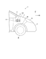
- 1 is a front left side view of an electric vehicle according to a first embodiment of the present invention.
- 1 is a front right side view of an electric vehicle according to a first embodiment of the present invention.
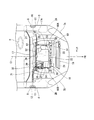
- 1 is a front top view of an electric vehicle according to a first embodiment of the present invention.
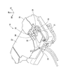
- It is a perspective view of the power control unit with which the electric vehicle concerning a 1st embodiment of the present invention is provided.
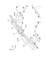
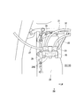
- It is the perspective view which showed the connection connector with which the said power control unit for connecting with the cable for charge is provided.
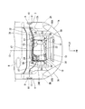
- It is a front top view of the electric vehicle which concerns on the 1st Embodiment of this invention, and is a figure which shows the state which changed the wiring of the cable for charging from the state shown in FIG.
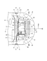
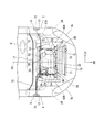
- FIG. 1 It is a front top view of the electric vehicle which concerns on the 2nd Embodiment of this invention. It is a principal part enlarged view of FIG. It is the perspective view which showed the connection connector with which the power control unit which concerns on 2nd Embodiment for connecting with the cable for charging is provided. It is a front top view of the electric vehicle which concerns on the 3rd Embodiment of this invention. It is a front top view of the electric vehicle which concerns on the 3rd Embodiment of this invention, and is a figure which shows the state which changed the wiring of the cable for charging from the state shown in FIG.
- the arrow FR indicates the front (traveling direction) of the vehicle
- the arrow UP indicates the upper side of the vehicle
- the arrow LH indicates the left side of the vehicle.
- First Embodiment> 1 and 2 show a vehicle front portion of an electric vehicle 1 to which the charging port structure according to the first embodiment of the present invention is applied.
- a left front fender 3 that covers the left front wheel 2 ⁇ / b> A and a right front fender 4 that covers the right front wheel 2 ⁇ / b> B are provided at the front portion of the electric vehicle 1, and between the left front fender 3 and the right front fender 4.
- a bumper 5 extending in the vehicle width direction is provided.
- the left front fender 3, the right front fender 4, and the bumper 5 form a pair of left and right wheel houses 6A and 6B, and the front wheels 2A and 2B are provided in the wheel houses 6A and 6B.
- a pair of left and right headlights 7A and 7B are provided above both sides of the bumper 5, and the rear portions of the headlights 7A and 7B are smoothly connected to the left front fender 3 and the right front fender 4, respectively.
- a bonnet (not shown) is provided between the upper portions of the left front fender 3 and the right front fender 4.
- the left front fender 3 is located above the front wheel 2A, and the left charging port 8 that is opened when charging power from a household power source is located above the front wheel 2B in the right front fender 4. Is provided with a right side charging port 9 that is opened when charging power from a quick charging power source.
- the charging ports 8 and 9 are covered with lids 14A and 14B so as to be opened and closed.
- the left charging port 8 is provided with a first attachment portion 11 for attaching a home power supply external connection connector portion 10 for connection to a home power supply.
- a second attachment portion 13 for attaching the quick connection external connection connector portion 12 for connection is provided.
- the home power supply external connection connector portion 10 is fixedly supported by the first attachment portion 11, and the quick charge external connection connector portion 12 is fixedly supported by the second attachment portion 13.
- the first attachment portion 11 is configured so that the quick connection external connection connector portion 12 can also be attached
- the second attachment portion 13 is configured so that the home power supply external connection connector portion 10 can also be attached.
- the 1st attachment part 11 and the 2nd attachment part 13 are comprised by the plate-shaped bracket etc. which are provided in a charging port, for example.
- a motor room 16 is formed between the left front fender 3 and the right front fender 4 below the bonnet.
- the rear part of the left front fender 3 and the rear part of the right front fender 4 are connected to both side parts of the dash panel 17 extending in the vehicle width direction to form the motor room 16.
- the motor room 16 and the vehicle compartment behind the motor room 16 are partitioned by a dash panel 17.
- the upper portion of the dash panel 17 extends relatively long toward the front of the vehicle.
- Reference numeral 17A in the figure indicates a dash panel upper portion 17A.
- the dash panel upper portion 17A is indicated by a two-dot chain line.
- a power control unit (hereinafter referred to as “PCU (Control Control Unit)”) 18 for controlling the motor is disposed in the center of the motor room 16 in the vehicle width direction, and a driving motor (not shown) is disposed below the PCU 18. .
- a radiator 19 is disposed in front of the PCU 18. The radiator 19 cools the coolant of the drive train including the motor and the PCU 18 and the coolant of the power storage device (not shown) by exchanging heat with the outside air that is traveling wind.
- the home power supply external connector 10 on the left charging port 8 side and the quick charging external connection connector 12 on the right charging port 9 side sandwich the PCU 18, in other words, the vehicle width direction center line C1. They are arranged at opposite positions (symmetric positions). Further, the front ends of the home power supply external connection connector portion 10 and the quick charge external connection connector portion 12 are located behind the front ends of the front wheels 2A and 2B, and the rear ends thereof are located forward of the dash panel 17. Yes.
- the electric vehicle 1 has a left handle specification, a handle H is provided on the left side of the passenger compartment, and the home power supply external connector 10 is attached to the left charging port 8 of the left front fender 3 on the handle H side.
- the quick-charge external connection connector portion 12 is attached to the right charging port 9 located on the passenger side.
- the PCU 18 has, in a top view, a rectangular case body 22, an inverter that converts power from the power storage device from direct current to alternating current, a control device that controls the inverter, and a home that can store power from a household power source in the power storage device.
- the PCU 18 is supported by a unit support frame 50 that has a rectangular frame shape when viewed from above.
- the unit support frame 50 is disposed so as to surround the four sides of the PCU 18.
- the unit support frame 50 is configured by joining a plurality of steel pipe members, and includes a front extension 51 located in front of the front wall of the PCU 18, a rear extension 52 located in the rear of the rear wall of the PCU 18, A left extension 53 that connects the left end of the front extension 51 and the left end of the rear extension 52, and the right end of the front extension 51 and the right end of the rear extension 52 And a right extending portion 54 to be coupled.
- the front left leg 55, the front right leg 56, the rear side are provided at the corners where the front extension 51, the rear extension 52, the left extension 53, and the right extension 54 are respectively coupled.
- the left leg 57 and the rear right leg 58 are formed so as to extend downward.
- the unit support frame 50 is held in a posture by fastening the lower ends of the leg portions 55 to 58 to the pair of left and right side frames 60A and 60B.
- the PCU 18 is fastened to appropriate positions of the front extension 51, the rear extension 52, the left extension 53, and the right extension 54, and is supported by the unit support frame 50.
- the side frames 60A and 60B extend in the vehicle front-rear direction on both sides of the PCU 18 in a top view.
- the home power charging device 20 includes an AC / DC converter and the like
- the quick charging device 21 includes a contactor for storing the voltage from the quick charging power source in a power storage device step by step. Has been.
- a charge cable 25 for inputting electric power into the PCU 18 is connected to a lower part on the right side of the rear wall of the case body 22 of the PCU 18.
- the charge cable 25 extends upward along the rear wall toward the inner side in the vehicle width direction.
- the charge cable 25 extends from the upper side of the upper wall of the case body 22 toward the left side, and a connection connector 24 is integrally provided at the tip thereof.
- connection connector 24 is attached to a bracket 24A fixed to the front side of the rear extension 52 of the unit support frame 50, and the attachment port faces leftward.
- connection connector 24 has the home power supply external connection connector portion 10 at one end and the home power supply internal connection connector portion 26 for connecting to the connection connector 24 at the other end. 27 is detachably connected via the home power supply internal connection connector portion 26.
- the home power supply charging cable 27 is connected to the connection connector 24 by inserting the home power supply internal connection connector portion 26 to the right with respect to the connection connector 24. As shown in FIG. 3, the household power supply charging cable 27 is extended from the connection connector 24 to the left along the rearward extending portion 52 of the unit support frame 50, and the household power supply external connection connector portion 10 is on the left side. It is routed so as to be located in the charging port 8. Here, the connection connector 24 is disposed in front of the home power supply external connection connector portion 10.
- the household power charging cable 27 is extended from the connection connector 24 to the left along the rearward extending portion 52 of the unit support frame 50, and is not routed above the case body 22. It is covered with a panel upper portion 17A. For this reason, when the bonnet is opened, the household power supply charging cable 27 does not stand out.
- an accommodating portion 28 that protrudes upward in a rectangular cross section and accommodates the quick charging device 21 is formed.
- a positive connector 29 and a negative connector 30 connected to the quick charging device 21 are provided so that the attachment opening faces rearward.
- the plus side quick charge cable 31 is connected to the plus connector 29.
- a negative quick charge cable 32 is connected to the negative connector 30.
- the positive-side quick charging cable 31 and the negative-side quick charging cable 32 are integrally provided with quick-charging internal connection connector portions 33 and 34 for connection to the positive connector 29 and the negative connector 30, respectively.
- the other ends of the plus-side quick charge cable 31 and the minus-side quick charge cable 32 are integrated with the quick-charge external connection connector portion 12.
- the external connection connector portion 12 for quick charge collectively holds the other end portions of the plus side quick charge cable 31 and the minus side quick charge cable 32.
- the plus-side quick charge cable 31 and the minus-side quick charge cable 32 are respectively inserted into the plus connector 29 and the minus connector 30 with the quick-charge internal connection connector portions 33 and 34 facing forward. It is detachably connected to the connector.
- the plus-side quick charge cable 31 and the minus-side quick charge cable 32 are each extended toward the right side, and are arranged so that the quick-charge external connection connector portion 12 is located in the right-side charging port 9. .
- the plus connector 29 and the minus connector 30 are disposed in front of the quick charge external connection connector portion 12.
- the household power source charging device 20 is connected to the household power source via the household power source charging cable 27 and the charging cable 25 when the household power source is connected to the household power source external connection connector unit 10. It is configured to be able to receive the power.
- the quick charge device 21 is connected to the positive side quick charge cable 31 and the negative side quick charge cable 31 when the power source for quick charge is connected to the positive side quick charge cable 31 and the negative side quick charge cable 32. It is configured to be able to receive power from the rapid charging power source via the cable 32.
- connection connector part 10 is configured to be attachable. For this reason, according to the handle
- an external connection for home power supply is connected to the right charging port 9 without modifying the basic structure of the vehicle.
- the connector part 10 can be simply provided. Thereby, the external connection connector portion 10 of the frequently used household power supply charging cable 27 is arranged at the charging port immediately after getting off the vehicle, and a good charging connector layout that can smoothly perform the charging operation, It can be easily realized regardless of the handle specification.
- the connecting portion (connecting connector 24) of the home power supply internal connection connector portion 26 of the home power supply charging cable 27 to the PCU 18 is provided on the upper side of the PCU 18 which is easy to access. It can be easy.
- connection connector 24 is different from that of the first embodiment.
- the same components as those in the first embodiment are denoted by the same reference numerals and the description thereof is omitted.
- a plate-like bracket 24B is attached to the rear part of the housing part 28 of the case body 22 so as to extend rearward, and the connection connector 24 is attached to the rear part of the bracket 24B. It has been.
- the connection connector 24 has an attachment port directed to the right, and a charge cable 25 is connected to the left end.
- the charge cable 25 extends upward along the rear wall of the case body 22, and then extends to the right and is coupled to the connection connector 24.
- the vehicle has a right-hand drive specification, and the home power charging cable 27 is extended from the connection connector 24 to the right.
- the home power supply external connector 10 is disposed in the right charging port 9.
- the positive connector 29 and the negative connector 30 for rapid charging are partially covered from above by a bracket 24B.
- the plus-side quick charge cable 31 and the minus-side quick charge cable 32 are passed to the left along the rearward extending portion 52 of the unit support frame 50 after passing below the connection connector 24.
- the quick connection external connection connector portion 12 is disposed at the left charging port 8.
- the home power charging cable 27 passes only above a part of the rear right side of the case body 22.
- the plus-side quick charging cable 31 and the minus-side quick charging cable 32 are extended to the left along the rearward extending portion 52 of the unit support frame 50. Almost no cables are routed above the case body 22 and are further covered with a dash panel upper portion 17A. For this reason, cables are not conspicuous when the hood is opened. Furthermore, the plus-side quick charge cable 31 and the minus-side quick charge cable 32 are passed below the connection connector 24 and intersect the connection connector 24, thereby improving the efficiency of arrangement of cables.
- the left charging port 8 and the right charging port 9 are in positions facing each other on the left and right sides, and the home power supply external connection connector portion of the home power charging cable 27 is located in either charging port. 10 can be attached.
- the home power supply external connection connector 10 of the home power supply charging cable 27 is simply connected to the charging port on the driver's seat according to the handle position of the right-hand drive car and the left-hand drive car. Can be configured to be located.
- connection connector 24 can be changed.
- the same components as those in the first and second embodiments are denoted by the same reference numerals and the description thereof is omitted.
- a plate-like bracket 24B is attached to the rear portion of the housing portion 28 of the case body 22 so as to extend rearward, and the rear portion of the bracket 24B.
- the connection connector 24 is attached to.
- the connection connector 24 faces the attachment port to the right.
- the handle H is disposed on the right side
- the home power supply external connection connector portion 10 is attached to the right charging port 9
- the quick charging external connection connector portion 12 is attached to the left charging port 8.
- connection connector 24 is configured to be removable together with the bracket 24B, and the connection connector 24 can be attached to the rearward extending portion 52 of the unit support frame 50 as shown in FIG.
- the mounting mode in this case is the same as that of the first embodiment, and the bracket 24A (see FIG. 5) is used.
- the bracket 24A instead of the bracket 24A, the rear extending portion 52 is detachably mounted. A bracket or the like may be used.
- the left side charging port 8 and the right side charging port 9 are comprised so that the external connection connector part 10 for household power supplies and the external connection connector part 12 for quick charging can be attached.
- connection connector 24 is removed together with the bracket 24 ⁇ / b> B at the rear of the housing portion 28, and the connection connector 24 is attached to the rearward extension portion 52.
- the home power supply external connection connector portion 10 and the quick charge external connection connector portion 12 can be interchanged. Therefore, according to the position of the handle H, the home power supply external connection connector 10 can be easily arranged closer to the driver. Further, in the present embodiment, since the arrangement position of the connection connector 24 can be changed, the bending of the home power supply charging cable 27, the positive side quick charging cable 31, and the negative side quick charging cable 32 is suppressed, These cables can be routed, and the cable routing can be made compact.
- the home power supply external connection connector portion 10 can be easily arranged at a position close to the driver according to the position of the handle.
- the present invention also includes a configuration in which the external power connector 9 for home power supply and the external connector of a high-voltage power supply cable can be attached to the right charging port 9. Further, the present invention includes a configuration in which the external connection connector portion 12 for quick charging and the external connection connector for a high-voltage power supply cable can be attached to the left charging port 8 and the right charging port 9. Even in such a case, a connector that is considered good for the user can be easily provided at either the left charging port 8 or the right charging port 9 according to the handle specification. That is, as shown in FIG.
- a charging port structure for an electric vehicle in which a power control unit 18 is arranged at the center in the vehicle width direction in a motor room 16 formed at the front of the vehicle.
- a charging device 70 that can store power from a charging power source in a power storage device
- a power feeding device 71 that can supply power stored in the power storage device to an external device.
- the power control unit 18 includes a first external connection connector 72 for connecting to a charging power source at one end, and a first internal connection for connecting to the charging device 70 at the other end.
- a charging cable 73 having a connector portion is connected via the first internal connection connector portion, and has a second external connection for connecting to an external device at one end.
- a power supply cable 75 having a connector part 74 and having a second internal connection connector part for connecting to the power supply device 71 at the other end is connected via the second internal connection connector part,
- the device 70 is configured to receive power from the charging power source via the charging cable 73, and the power feeding device 71 is configured to be able to transmit power from the power storage device via the power feeding cable 75.
- Charging ports 8 and 9 are provided in the left front fender 3 that is arranged on the left side of the vehicle front and forms the motor room 16, and the right front fender 4 that is arranged on the right side of the front of the vehicle and forms the motor room 16, respectively.
- the left and right charging ports 8 and 9 are in positions facing each other with the power control unit 18 in between, and the left and right charging ports 8 and 9 are both connected to the charging cable 73 and
- the first external connection connector portion 72 and the second external connection connector portion 74 of the electric cable 75 are configured to be attachable, and the charging port 8 arranged on the driver's seat side among the left and right charging ports 8 and 9 is provided.
- the first external connection connector portion 72 of the charging cable 73 is attached, and the second external connection connector portion 74 of the power supply cable 75 is attached to the charging port 9 arranged on the passenger side.
- the charging port is located at the left and right opposing positions, and the external connection connector of the home power charging cable can be attached to either charging port.
- the handle position of the left-hand drive car it is possible to simply configure the external connection connector of the home power supply charging cable at the charging port on the driver's seat side.
- the external connection connector of the frequently used household power supply cable is placed at the charging port immediately after getting off the vehicle, and a good charging connector layout that allows smooth charging work has been made into a handle specification. It can be realized easily.
Landscapes
- Engineering & Computer Science (AREA)
- Power Engineering (AREA)
- Transportation (AREA)
- Mechanical Engineering (AREA)
- Life Sciences & Earth Sciences (AREA)
- Sustainable Development (AREA)
- Sustainable Energy (AREA)
- Electric Propulsion And Braking For Vehicles (AREA)
- Arrangement Or Mounting Of Propulsion Units For Vehicles (AREA)
Abstract
この電気自動車の充電口構造は、パワーコントロールユニットが配置される電気自動車の充電口構造であって、前記パワーコントロールユニットの内部に、家庭電源充電用デバイスと、急速充電用デバイスと、が設けられ、前記パワーコントロールユニットには、一端に第1の外部接続コネクタ部を有し、かつ他端に第1の内部接続コネクタ部を有する家庭電源充電用ケーブルが、前記第1の内部接続コネクタ部を介して接続されるとともに、一端に第2の外部接続コネクタ部を有し、かつ他端に第2の内部接続コネクタ部を有する急速充電用ケーブルが、前記第2の内部接続コネクタ部を介して接続され、左フロントフェンダ、及び、右フロントフェンダのそれぞれに、充電口が設けられ、運転席側に配される前記充電口に、前記第1の外部接続コネクタ部が取り付けられ、同乗者側に配される前記充電口に、前記第2の外部接続コネクタ部が取り付けられる。
Description
本発明は、電気自動車の充電口構造に関する。
本願は、2011年11月14日に、日本に出願された特願2011-248160号に基づき優先権を主張し、その内容をここに援用する。
本願は、2011年11月14日に、日本に出願された特願2011-248160号に基づき優先権を主張し、その内容をここに援用する。
特許文献1には、車両の前部に充電口が形成され、この充電口内に、家庭用電源による充電を可能とする充電コネクタ(充電ポート)と、この家庭用電源用の充電コネクタからの充電よりも速い充電速度での充電を可能とする急速充電用の充電コネクタ(充電ポート)と、が設けられる電気自動車が開示されている。
上記従来の電気自動車では、充電時にユーザが車両前方まで移動して充電作業を行う必要があるため、作業に手間がかかり、また、充電口に対する前突時の影響が大きい。このため、この種の車両では充電口を車両の側部に設け、この充電口内に充電コネクタを設けるものもある。このように車両の側部に充電口を設けた場合には、ユーザと充電口との距離を車両前部に充電口がある場合に比べて短くすることができるので、使い勝手を良いものにできるといえる。
ところで、車両の側部に充電口を設ける場合、左右側部に充電口を振り分けて設け、左右のいずれか一方に家庭用電源用の充電コネクタを設け、他方に急速充電用の充電コネクタを設ける態様が考えられるが、車両にあってはハンドルが左右のいずれかに設定される。この場合に、ハンドルの位置に応じ、ユーザにとって使い勝手の良い充電口に、所望の充電コネクタを配置することが好ましい。ここで、ハンドルの位置に応じて、家庭用電源用の充電コネクタと急速充電用の充電コネクタとを選択して左右の充電口に取り付けることができれば、ユーザにとって良好な充電コネクタの配置を簡易に実現することができる。
そこで、本発明は、充電口内に設けられる充電コネクタのユーザにとって良好なレイアウトを、ハンドル仕様によらず簡易に実現することができる電気自動車の充電口構造の提供を目的とする。
上記課題の解決手段として、本発明の態様は以下の構成を有する。
(1)本発明の一態様に係る電気自動車の充電口構造は、車両前部に形成されるモータルーム内の車幅方向中央にパワーコントロールユニットが配置される電気自動車の充電口構造であって、前記パワーコントロールユニットの内部に、家庭用電源からの電力を蓄電装置に蓄電可能とする家庭電源充電用デバイスと、急速充電用電源からの電力を、前記家庭用電源からの充電に比べて速い充電速度で前記蓄電装置に蓄電可能とする急速充電用デバイスと、が設けられ、前記パワーコントロールユニットには、一端に前記家庭用電源と接続するための第1の外部接続コネクタ部を有し、かつ他端に前記パワーコントロールユニットと接続するための第1の内部接続コネクタ部を有する家庭電源充電用ケーブルが、前記第1の内部接続コネクタ部を介して接続されるとともに、一端に前記急速充電用電源と接続するための第2の外部接続コネクタ部を有し、かつ他端に前記パワーコントロールユニットと接続するための第2の内部接続コネクタ部を有する急速充電用ケーブルが、前記第2の内部接続コネクタ部を介して接続され、前記家庭電源充電用デバイスは、前記家庭電源充電用ケーブルを介して前記家庭用電源からの電力を受電可能に構成されるとともに、前記急速充電用デバイスは、前記急速充電用ケーブルを介して前記急速充電用電源からの電力を受電可能に構成され、車両前部左側に配されて前記モータルームを形成する左フロントフェンダ、及び、車両前部右側に配されて前記モータルームを形成する右フロントフェンダのそれぞれに、充電口が設けられ、左右の前記充電口は、前記パワーコントロールユニットを挟んで対向する位置にあり、左右の前記充電口はいずれも、前記家庭電源充電用ケーブル及び前記急速充電用ケーブルの前記第1の外部接続コネクタ部及び前記第2の外部接続コネクタ部を取り付け可能に構成され、左右の前記充電口のうち、運転席側に配される前記充電口に、前記家庭電源充電用ケーブルの前記第1の外部接続コネクタ部が取り付けられ、同乗者側に配される前記充電口に、前記急速充電用ケーブルの前記第2の外部接続コネクタ部が取り付けられる。
(1)本発明の一態様に係る電気自動車の充電口構造は、車両前部に形成されるモータルーム内の車幅方向中央にパワーコントロールユニットが配置される電気自動車の充電口構造であって、前記パワーコントロールユニットの内部に、家庭用電源からの電力を蓄電装置に蓄電可能とする家庭電源充電用デバイスと、急速充電用電源からの電力を、前記家庭用電源からの充電に比べて速い充電速度で前記蓄電装置に蓄電可能とする急速充電用デバイスと、が設けられ、前記パワーコントロールユニットには、一端に前記家庭用電源と接続するための第1の外部接続コネクタ部を有し、かつ他端に前記パワーコントロールユニットと接続するための第1の内部接続コネクタ部を有する家庭電源充電用ケーブルが、前記第1の内部接続コネクタ部を介して接続されるとともに、一端に前記急速充電用電源と接続するための第2の外部接続コネクタ部を有し、かつ他端に前記パワーコントロールユニットと接続するための第2の内部接続コネクタ部を有する急速充電用ケーブルが、前記第2の内部接続コネクタ部を介して接続され、前記家庭電源充電用デバイスは、前記家庭電源充電用ケーブルを介して前記家庭用電源からの電力を受電可能に構成されるとともに、前記急速充電用デバイスは、前記急速充電用ケーブルを介して前記急速充電用電源からの電力を受電可能に構成され、車両前部左側に配されて前記モータルームを形成する左フロントフェンダ、及び、車両前部右側に配されて前記モータルームを形成する右フロントフェンダのそれぞれに、充電口が設けられ、左右の前記充電口は、前記パワーコントロールユニットを挟んで対向する位置にあり、左右の前記充電口はいずれも、前記家庭電源充電用ケーブル及び前記急速充電用ケーブルの前記第1の外部接続コネクタ部及び前記第2の外部接続コネクタ部を取り付け可能に構成され、左右の前記充電口のうち、運転席側に配される前記充電口に、前記家庭電源充電用ケーブルの前記第1の外部接続コネクタ部が取り付けられ、同乗者側に配される前記充電口に、前記急速充電用ケーブルの前記第2の外部接続コネクタ部が取り付けられる。
(2)上記(1)に記載の電気自動車の充電口構造は、前記パワーコントロールユニットの上部側に、前記家庭電源充電用ケーブルの前記第1の内部接続コネクタ部が接続される接続部が設けられてもよい。
(3)本発明の別態様に係る電気自動車の充電口構造は、車両前部に形成されるモータルーム内の車幅方向中央にパワーコントロールユニットが配置される電気自動車の充電口構造であって、前記パワーコントロールユニットの内部に、充電用電源からの電力を蓄電装置に蓄電可能とする充電用デバイスと、前記蓄電装置に蓄電した電力を外部装置に給電可能とする給電用デバイスと、が設けられ、前記パワーコントロールユニットには、一端に前記充電用電源と接続するための第1の外部接続コネクタ部を有し、かつ他端に前記充電用デバイスと接続するための第1の内部接続コネクタ部を有する充電用ケーブルが、前記第1の内部接続コネクタ部を介して接続されるとともに、一端に前記外部装置と接続するための第2の外部接続コネクタ部を有し、かつ他端に前記給電用デバイスと接続するための第2の内部接続コネクタ部を有する給電用ケーブルが、前記第2の内部接続コネクタ部を介して接続され、前記充電用デバイスは、前記充電用ケーブルを介して前記充電用電源からの電力を受電可能に構成されるとともに、前記給電用デバイスは、前記給電用ケーブルを介して前記蓄電装置からの電力を送電可能に構成され、車両前部左側に配されて前記モータルームを形成する左フロントフェンダ、及び、車両前部右側に配されて前記モータルームを形成する右フロントフェンダのそれぞれに、充電口が設けられ、左右の前記充電口は、前記パワーコントロールユニットを挟んで対向する位置にあり、左右の前記充電口はいずれも、前記充電用ケーブル及び前記給電用ケーブルの前記第1の外部接続コネクタ部及び前記第2の外部接続コネクタ部を取り付け可能に構成され、左右の前記充電口のうち、運転席側に配される前記充電口に、前記充電用ケーブルの前記第1の外部接続コネクタ部が取り付けられ、同乗者側に配される前記充電口に、前記給電用ケーブルの前記第2の外部接続コネクタ部が取り付けられる。
上記(1)に記載の電気自動車の充電口構造によれば、充電口が左右で対向する位置にあり、どちらの充電口にも家庭電源充電用ケーブルの外部接続コネクタが取り付け可能であるため、右ハンドル車、左ハンドル車のハンドル位置に応じて、簡易に、運転席側の充電口に家庭電源充電用ケーブルの外部接続コネクタが位置するように構成できる。これにより、車両を降りてすぐの充電口に、頻繁に使用する家庭電源充電用ケーブルの外部接続コネクタが配置され、スムーズに充電作業を行うことができる良好な充電コネクタのレイアウトを、ハンドル仕様によらず簡易に実現することができる。
上記(2)に記載の電気自動車の充電口構造によれば、家庭電源充電用ケーブルの内部接続コネクタ部のパワーコントロールユニットに対する接続部が、アクセスし易いパワーコントロールユニットの上部側に設けられるため、メンテナンス性を容易なものにできる。
以下、本発明の実施形態について説明する。なお、以下で用いる図面において、矢印FRは車両の前方(進行方向)を示し、矢印UPは車両の上方を示し、矢印LHは車両の左方を示している。
<第1の実施形態>
図1、図2には、本発明の第1の実施形態に係る充電口構造が適用された電気自動車1の車両前部が示されている。電気自動車1の車両前部には、左の前輪2Aを覆う左フロントフェンダ3と、右の前輪2Bを覆う右フロントフェンダ4が設けられ、左フロントフェンダ3と右フロントフェンダ4との間には車幅方向に延在するバンパ5が設けられている。左フロントフェンダ3、右フロントフェンダ4、及びバンパ5によって、左右一対のホイールハウス6Aと6Bが形成され、これらホイールハウス6Aと6B内に、前輪2Aと2Bが設けられている。
図1、図2には、本発明の第1の実施形態に係る充電口構造が適用された電気自動車1の車両前部が示されている。電気自動車1の車両前部には、左の前輪2Aを覆う左フロントフェンダ3と、右の前輪2Bを覆う右フロントフェンダ4が設けられ、左フロントフェンダ3と右フロントフェンダ4との間には車幅方向に延在するバンパ5が設けられている。左フロントフェンダ3、右フロントフェンダ4、及びバンパ5によって、左右一対のホイールハウス6Aと6Bが形成され、これらホイールハウス6Aと6B内に、前輪2Aと2Bが設けられている。
バンパ5の両側部の上方には、左右一対のヘッドライト7A、7Bが設けられ、ヘッドライト7A、7Bの後部はそれぞれ、左フロントフェンダ3と右フロントフェンダ4とに滑らかに連なっている。また、左フロントフェンダ3と右フロントフェンダ4との上部間には、図示省略するボンネットが設けられている。
左フロントフェンダ3において前輪2Aよりも上方に位置する部位には、家庭用電源から電力を充電する際に開放する左側充電口8が、右フロントフェンダ4において前輪2Bよりも上方に位置する部位には、急速充電用電源から電力を充電する際に開放する右側充電口9が設けられている。各充電口8、9は、リッド14A、14Bに開閉可能に覆われる。
左側充電口8内には、家庭用電源と接続するための家庭電源用外部接続コネクタ部10を取り付けるための第1の取り付け部11が設けられ、右側充電口9内には急速充電用電源と接続するための急速充電用外部接続コネクタ部12を取り付けるための第2の取り付け部13が設けられている。第1の取り付け部11によって家庭電源用外部接続コネクタ部10が固定支持され、第2の取り付け部13によって急速充電用外部接続コネクタ部12が固定支持されている。本実施形態において、第1の取り付け部11は急速充電用外部接続コネクタ部12も取り付け可能に構成され、第2の取り付け部13は家庭電源用外部接続コネクタ部10も取り付け可能に構成されている。なお、第1の取り付け部11、第2の取り付け部13は、例えば充電口内に設けられる板状のブラケット等で構成される。
図3を参照し、ボンネットの下方であって、左フロントフェンダ3と右フロントフェンダ4との間には、モータルーム16が形成される。左フロントフェンダ3の後部、及び右フロントフェンダ4の後部は、車幅方向に延在するダッシュパネル17の両側部に連なって、上記モータルーム16を形成している。モータルーム16とその後方の車室はダッシュパネル17によって区画されている。本実施形態においてダッシュパネル17の上部は、車両前方に向けて比較的長く延びている。図中符合17Aはダッシュパネルアッパ部17Aを示している。説明便宜上、ダッシュパネルアッパ部17Aは二点鎖線で示している。
モータルーム16内の車幅方向略中央に、モータを制御するパワーコントロールユニット(以下、PCU(Power Control Unit))18が配置され、PCU18の下方に図示省略する駆動用のモータが配置されている。PCU18の前方には、ラジエータ19が配置されている。このラジエータ19は、モータとPCU18を含むドライブトレインの冷却液と、図示しない蓄電装置の冷却液を、走行風である外気と熱交換することにより冷却する。
左側充電口8側の家庭電源用外部接続コネクタ部10と、右側充電口9側の急速充電用外部接続コネクタ部12は、PCU18を挟んで、換言すれば、車幅方向中心線C1を挟んで対向する位置(対称の位置)に配置されている。また、家庭電源用外部接続コネクタ部10及び急速充電用外部接続コネクタ部12それぞれの前端は、前輪2A、2Bの前端よりも後方であって、その後端はダッシュパネル17よりも前方に位置している。
ここで、電気自動車1は左ハンドル仕様であり、車室左側にハンドルHが設けられ、家庭電源用外部接続コネクタ部10は、ハンドルH側の左フロントフェンダ3の左側充電口8に取り付けられ、急速充電用外部接続コネクタ部12は、同乗者側に位置する右側充電口9に取り付けられている。
PCU18は、上面視で矩形のケース本体22に、蓄電装置からの電力を直流から交流に変換するインバータ、このインバータを制御する制御装置、家庭用電源からの電力を蓄電装置に蓄電可能とする家庭電源充電用デバイス、及び家庭用電源よりも電圧の高い急速充電用電源からの電力を、家庭用電源からの充電に比べて速い充電速度で蓄電装置に蓄電可能とする急速充電用デバイス等を収容して構成されている。
PCU18は、上面視で矩形枠状を呈するユニット支持フレーム50に支持される。ユニット支持フレーム50は、PCU18の四辺を囲むように配置されている。ユニット支持フレーム50は複数の鋼管材を接合して構成されており、PCU18の前壁の前方に位置する前方延在部51と、PCU18の後壁の後方に位置する後方延在部52と、前方延在部51の左側端部及び後方延在部52の左側端部を結合する左方延在部53と、前方延在部51の右側端部及び後方延在部52の右側端部を結合する右方延在部54と、を有している。
前方延在部51、後方延在部52、左方延在部53、及び右方延在部54が夫々結合する各角部には、前側左脚部55、前側右脚部56、後側左脚部57、及び後側右脚部58が下方に向けて延びるように形成される。ユニット支持フレーム50は、これら各脚部55~58の下端部が左右一対のサイドフレーム60A、60Bに締結されることで姿勢が保持されている。そしてPCU18は、前方延在部51、後方延在部52、左方延在部53、及び右方延在部54の適所に締結されて、ユニット支持フレーム50によって支持されている。なお、サイドフレーム60A、60Bは上面視でPCU18の両側方で車両前後方向に延在している。
図3において、説明便宜上、PCU18内に収容される家庭電源充電用デバイス20及び急速充電用デバイス21を図示している。家庭電源充電用デバイス20は、AC/DCコンバータ等を含んで構成され、急速充電用デバイス21は、急速充電用電源からの電圧を段階的に蓄電装置に蓄電するためのコンタクタ等を含んで構成されている。
図4を参照し、PCU18のケース本体22の後壁右側の下部には電力をPCU18内に入力するためのチャージケーブル25が接続される。チャージケーブル25は、車幅方向内側に向けて前記後壁に沿って上方へ延びている。
図5を参照し、チャージケーブル25は、ケース本体22の上壁の上方から左方に向けて延び、そして、その先端には接続コネクタ24が一体に設けられている。
図5を参照し、チャージケーブル25は、ケース本体22の上壁の上方から左方に向けて延び、そして、その先端には接続コネクタ24が一体に設けられている。
接続コネクタ24は、ユニット支持フレーム50の後方延在部52の前部側に固着されたブラケット24Aに取り付けられ、その取り付け口を左方に向けている。ここで、接続コネクタ24には、一端に上記家庭電源用外部接続コネクタ部10を有し、他端に接続コネクタ24に接続するための家庭電源用内部接続コネクタ部26を有する家庭電源充電用ケーブル27が、前記家庭電源用内部接続コネクタ部26を介して着脱可能に接続されている。
家庭電源充電用ケーブル27は、家庭電源用内部接続コネクタ部26を接続コネクタ24に対し右方に向けて挿入することで、接続コネクタ24に接続されている。そして図3に示すように、家庭電源充電用ケーブル27は、接続コネクタ24からユニット支持フレーム50の後方延在部52に沿って左方に延ばされ、家庭電源用外部接続コネクタ部10が左側充電口8内に位置するように配索されている。ここで、接続コネクタ24は、家庭電源用外部接続コネクタ部10よりも前方に配置されている。
また本実施形態では、家庭電源充電用ケーブル27が接続コネクタ24からユニット支持フレーム50の後方延在部52に沿って左方に延ばされ、ケース本体22の上方に配索されず、さらにダッシュパネルアッパ部17Aで覆われている。このため、ボンネットを開放させた際に家庭電源充電用ケーブル27が目立たないようになっている。
一方で、図4に示すように、PCU18のケース本体22の右側上部の前側には、横断面矩形で上方に突出し、急速充電用デバイス21を収容する収容部28が形成され、収容部28の後壁部には、急速充電用デバイス21に接続するプラスコネクタ29とマイナスコネクタ30とがそれぞれ、後方に取り付け口を向けるようにして設けられている。
プラスコネクタ29にはプラス側急速充電用ケーブル31が接続される。マイナスコネクタ30にはマイナス側急速充電用ケーブル32が接続される。プラス側急速充電用ケーブル31及びマイナス側急速充電用ケーブル32はそれぞれ一端側に、プラスコネクタ29及びマイナスコネクタ30に接続するための急速充電用内部接続コネクタ部33、34を一体に有している。また、図3に示すように、プラス側急速充電用ケーブル31及びマイナス側急速充電用ケーブル32の他端側は、上記急速充電用外部接続コネクタ部12に一体化されている。急速充電用外部接続コネクタ部12は、プラス側急速充電用ケーブル31及びマイナス側急速充電用ケーブル32の他端部を纏めて保持している。
そしてプラス側急速充電用ケーブル31及びマイナス側急速充電用ケーブル32はそれぞれ、急速充電用内部接続コネクタ部33,34を、プラスコネクタ29及びマイナスコネクタ30に対し前方に向けて挿入することで、各コネクタに着脱可能に接続されている。
プラス側急速充電用ケーブル31及びマイナス側急速充電用ケーブル32はそれぞれ、右側に向けて延ばされ、急速充電用外部接続コネクタ部12が右側充電口9内に位置するように配索されている。ここで、プラスコネクタ29及びマイナスコネクタ30は、急速充電用外部接続コネクタ部12よりも前方に配置されている。
プラス側急速充電用ケーブル31及びマイナス側急速充電用ケーブル32はそれぞれ、右側に向けて延ばされ、急速充電用外部接続コネクタ部12が右側充電口9内に位置するように配索されている。ここで、プラスコネクタ29及びマイナスコネクタ30は、急速充電用外部接続コネクタ部12よりも前方に配置されている。
なお、上記構成において、家庭電源充電用デバイス20は、家庭電源用外部接続コネクタ部10に家庭用電源が接続された際に、家庭電源充電用ケーブル27及びチャージケーブル25を介して家庭用電源からの電力を受電可能に構成されている。一方、急速充電用デバイス21は、プラス側急速充電用ケーブル31及びマイナス側急速充電用ケーブル32に急速充電用電源が接続された際に、これらプラス側急速充電用ケーブル31及びマイナス側急速充電用ケーブル32を介して急速充電用電源からの電力を受電可能に構成されている。
以上に説明した上記電気自動車1では、左側充電口8と右側充電口9が左右で対向する位置にあり、上述したように、どちらの充電口にも家庭電源充電用ケーブル27の家庭電源用外部接続コネクタ部10が取り付け可能に構成されている。このため、右ハンドル車、左ハンドル車のハンドル位置に応じて、簡易に、運転席側の充電口に家庭電源充電用ケーブル27の外部接続コネクタ部10が位置するように構成できる。
すなわち、具体的には、図6に示すように、車室右側にハンドルHが設けられる車両仕様の場合において、車両の基本的構造を改変することなく、右側充電口9に家庭電源用外部接続コネクタ部10を簡易に設けることができるようになっている。これにより、車両を降りてすぐの充電口に、頻繁に使用する家庭電源充電用ケーブル27の外部接続コネクタ部10が配置され、スムーズに充電作業を行うことができる良好な充電コネクタのレイアウトを、ハンドル仕様によらず簡易に実現することができるようになっている。
すなわち、具体的には、図6に示すように、車室右側にハンドルHが設けられる車両仕様の場合において、車両の基本的構造を改変することなく、右側充電口9に家庭電源用外部接続コネクタ部10を簡易に設けることができるようになっている。これにより、車両を降りてすぐの充電口に、頻繁に使用する家庭電源充電用ケーブル27の外部接続コネクタ部10が配置され、スムーズに充電作業を行うことができる良好な充電コネクタのレイアウトを、ハンドル仕様によらず簡易に実現することができるようになっている。
さらに、この電気自動車1では、家庭電源充電用ケーブル27の家庭電源用内部接続コネクタ部26のPCU18に対する接続部(接続コネクタ24)が、アクセスし易いPCU18の上部側に設けられるため、メンテナンス性を容易なものにできる。
<第2の実施形態>
次に本発明の第2の実施形態について図7~図9を用いて説明する。この実施形態では、接続コネクタ24の配置が第1の実施形態と異なっている。以下の説明において、第1の実施形態と同様の構成要素については、同一符合で示し説明を省略する。
次に本発明の第2の実施形態について図7~図9を用いて説明する。この実施形態では、接続コネクタ24の配置が第1の実施形態と異なっている。以下の説明において、第1の実施形態と同様の構成要素については、同一符合で示し説明を省略する。
図7~図9に示すように、本実施形態では、ケース本体22の収容部28の後部に板状のブラケット24Bが後方に延びるように取り付けられ、このブラケット24Bの後部に接続コネクタ24が取り付けられている。接続コネクタ24は右方に取り付け口を向けており、左端部にチャージケーブル25が接続されている。チャージケーブル25は、ケース本体22の後壁に沿って上方へ延び、その後、右方に向けて延ばされ接続コネクタ24に結合されている。
本実施形態では、車両が右ハンドル仕様であり、家庭電源充電用ケーブル27は接続コネクタ24から右方に延ばされる。家庭電源用外部接続コネクタ部10は、右側充電口9内に配置されている。
急速充電用のプラスコネクタ29及びマイナスコネクタ30は、ブラケット24Bによって一部上方から覆われている。プラス側急速充電用ケーブル31及びマイナス側急速充電用ケーブル32は、接続コネクタ24の下方を通された後、ユニット支持フレーム50の後方延在部52に沿って左方に延ばされる。急速充電用外部接続コネクタ部12は、左側充電口8に配置されている。
本実施形態では、家庭電源充電用ケーブル27がケース本体22の後部右側の一部のみの上方を通る。プラス側急速充電用ケーブル31及びマイナス側急速充電用ケーブル32は、ユニット支持フレーム50の後方延在部52に沿って左方に延ばされる。ケース本体22の上方にはケーブル類が殆ど配索されず、さらにダッシュパネルアッパ部17Aで覆われている。このため、ボンネットを開放させた際にケーブル類が目立たないようになっている。さらに、プラス側急速充電用ケーブル31及びマイナス側急速充電用ケーブル32を、接続コネクタ24の下方に通して接続コネクタ24と交差させることで、ケーブル類の配置スペースの効率化が図られている。
以上に説明した第2の実施形態においても、左側充電口8と右側充電口9が左右で対向する位置にあり、どちらの充電口にも家庭電源充電用ケーブル27の家庭電源用外部接続コネクタ部10が取り付け可能とされている。
これにより、第1の実施形態と同様に右ハンドル車、左ハンドル車のハンドル位置に応じて、簡易に、運転席側の充電口に家庭電源充電用ケーブル27の家庭電源用外部接続コネクタ部10が位置するように構成できる。
これにより、第1の実施形態と同様に右ハンドル車、左ハンドル車のハンドル位置に応じて、簡易に、運転席側の充電口に家庭電源充電用ケーブル27の家庭電源用外部接続コネクタ部10が位置するように構成できる。
<第3の実施形態>
次に本発明の第3の実施形態について図10~図12を用いて説明する。この実施形態は、上記接続コネクタ24の配置位置を変更できるようになっている。以下の説明において、第1,2の実施形態と同様の構成要素については、同一符合で示し説明を省略する。
次に本発明の第3の実施形態について図10~図12を用いて説明する。この実施形態は、上記接続コネクタ24の配置位置を変更できるようになっている。以下の説明において、第1,2の実施形態と同様の構成要素については、同一符合で示し説明を省略する。
本実施形態では、図10に示すように、第2の実施形態と同様に、ケース本体22の収容部28の後部に板状のブラケット24Bが後方に延びるように取り付けられ、このブラケット24Bの後部に接続コネクタ24が取り付けられている。接続コネクタ24は右方に取り付け口を向けている。ここで、ハンドルHは右側に配置され、家庭電源用外部接続コネクタ部10は右側充電口9に、急速充電用外部接続コネクタ部12は左側充電口8に取り付けられている。
そして本実施形態では、接続コネクタ24がブラケット24Bとともに取り外し可能に構成されていて、図11に示すように、接続コネクタ24をユニット支持フレーム50の後方延在部52に取り付け可能になっている。この場合の取り付け態様は、第1の実施形態と同様であり、ブラケット24A(図5参照)が用いられるものとするが、例えば、ブラケット24Aに代えて、後方延在部52に着脱可能に取り付けられるブラケット等を用いてもよい。
そして、本実施形態においても左側充電口8及び右側充電口9は、家庭電源用外部接続コネクタ部10及び急速充電用外部接続コネクタ部12を取り付け可能に構成されている。
この第3の実施形態の構成では、図10に示す状態から、収容部28の後部のブラケット24Bとともに接続コネクタ24を取り外し、後方延在部52に接続コネクタ24を取り付けた上で、図11に示すように、家庭電源用外部接続コネクタ部10と、急速充電用外部接続コネクタ部12と、を入れ替えることができる。したがって、ハンドルHの位置に応じて、運転者に近い方に家庭電源用外部接続コネクタ部10を簡易に配置することができるようになっている。そして、さらに本実施形態では、接続コネクタ24の配置位置が変更可能であるので、家庭電源充電用ケーブル27、プラス側急速充電用ケーブル31及びマイナス側急速充電用ケーブル32の湾曲を抑制して、これらケーブルを配索することができるとともに、ケーブルの配索をコンパクトにすることも可能となる。
なお、図12は、図11に示す状態から、プラス側急速充電用ケーブル31及びマイナス側急速充電用ケーブル32を取り除いた状態を示している。仮に急速充電が必要とされない場合には、充電口に急速充電用の外部接続コネクタを設けなくてもよい。しかしながら、本発明の基本的な構成を備えていれば、ハンドルの位置に応じて家庭電源用外部接続コネクタ部10を簡易に運転者に近い位置に配置することができることに変わりはない。
以上、本発明の実施形態について説明したが、本発明は上記した実施形態に限定されるものではなく、その趣旨を逸脱しない範囲で適宜変更可能である。
例えば、上記実施形態では、左側充電口8及び右側充電口9に、家庭電源用外部接続コネクタ部10及び急速充電用外部接続コネクタ部12を取り付け可能な構成を説明したが、左側充電口8及び右側充電口9に、家庭電源用外部接続コネクタ部10及び給電用の高圧ケーブルの外部接続コネクタを取り付け可能とする構成も本発明に含まれる。また、左側充電口8及び右側充電口9に、急速充電用外部接続コネクタ部12及び給電用の高圧ケーブルの外部接続コネクタを取り付け可能とする構成も本発明に含まれる。このような場合にあっても、ハンドル仕様に応じて、左側充電口8及び右側充電口9のいずれかに、ユーザにとって良好と考えられるコネクタを簡易に設けることができる。すなわち、図13に示すように、第4の実施形態として、車両前部に形成されるモータルーム16内の車幅方向中央にパワーコントロールユニット18が配置される電気自動車の充電口構造であって、パワーコントロールユニット18の内部に、充電用電源からの電力を蓄電装置に蓄電可能とする充電用デバイス70と、蓄電装置に蓄電した電力を外部装置に給電可能とする給電用デバイス71と、が設けられ、パワーコントロールユニット18には、一端に充電用電源と接続するための第1の外部接続コネクタ部72を有し、かつ他端に充電用デバイス70と接続するための第1の内部接続コネクタ部を有する充電用ケーブル73が、第1の内部接続コネクタ部を介して接続されるとともに、一端に外部装置と接続するための第2の外部接続コネクタ部74を有し、かつ他端に給電用デバイス71と接続するための第2の内部接続コネクタ部を有する給電用ケーブル75が、第2の内部接続コネクタ部を介して接続され、充電用デバイス70は、充電用ケーブル73を介して充電用電源からの電力を受電可能に構成されるとともに、給電用デバイス71は、給電用ケーブル75を介して蓄電装置からの電力を送電可能に構成され、車両前部左側に配されてモータルーム16を形成する左フロントフェンダ3、及び、車両前部右側に配されてモータルーム16を形成する右フロントフェンダ4のそれぞれに、充電口8、9が設けられ、左右の充電口8、9は、パワーコントロールユニット18を挟んで対向する位置にあり、左右の充電口8、9はいずれも、充電用ケーブル73及び給電用ケーブル75の第1の外部接続コネクタ部72及び第2の外部接続コネクタ部74を取り付け可能に構成され、左右の充電口8、9のうち、運転席側に配される充電口8に、充電用ケーブル73の第1の外部接続コネクタ部72が取り付けられ、同乗者側に配される充電口9に、給電用ケーブル75の第2の外部接続コネクタ部74が取り付けられる。
本発明にかかる電気自動車の充電口構造によれば、充電口が左右で対向する位置にあり、どちらの充電口にも家庭電源充電用ケーブルの外部接続コネクタが取り付け可能であるため、右ハンドル車、左ハンドル車のハンドル位置に応じて、簡易に、運転席側の充電口に家庭電源充電用ケーブルの外部接続コネクタが位置するように構成できる。これにより、車両を降りてすぐの充電口に、頻繁に使用する家庭電源充電用ケーブルの外部接続コネクタが配置され、スムーズに充電作業を行うことができる良好な充電コネクタのレイアウトを、ハンドル仕様によらず簡易に実現することができる。
1 電気自動車
2A 左の前輪
2B 右の前輪
3 左フロントフェンダ
4 右フロントフェンダ
5 バンパ
6A、6B ホイールハウス
7A、7B ヘッドライト
8 左側充電口(充電口)
9 右側充電口(充電口)
10 家庭電源用外部接続コネクタ部(第1の外部接続コネクタ部)
11 第1の取り付け部
12 急速充電用外部接続コネクタ部(第2の外部接続コネクタ部)
13 第2の取り付け部
14A、14B リッド
16 モータルーム
17 ダッシュパネル
17A ダッシュパネルアッパ部
18 パワーコントロールユニット
19 ラジエータ
20 家庭電源充電用デバイス
21 急速充電用デバイス
22 ケース本体
24 接続コネクタ(接続部)
24A、24B ブラケット
25 チャージケーブル
26 家庭電源用内部接続コネクタ部(第1の内部接続コネクタ部)
27 家庭電源充電用ケーブル
28 収容部
29 プラスコネクタ
30 マイナスコネクタ
31 プラス側急速充電用ケーブル(急速充電用ケーブル)
32 マイナス側急速充電用ケーブル(急速充電用ケーブル)
33、34 急速充電用内部接続コネクタ部(第2の内部接続コネクタ部)
50 ユニット支持フレーム
51 前方延在部
52 後方延在部
53 左方延在部
54 右方延在部
55 前側左脚部
56 前側右脚部
57 後側左脚部
58 後側右脚部
60A、60B サイドフレーム
70 充電用デバイス
71 給電用デバイス
72 外部接続コネクタ部
73 充電用ケーブル
74 外部接続コネクタ部
75 給電用ケーブル
C1 車幅方向中心線
H ハンドル
FR 車両の前方(進行方向)
LH 車両の左方
UP 車両の上方
2A 左の前輪
2B 右の前輪
3 左フロントフェンダ
4 右フロントフェンダ
5 バンパ
6A、6B ホイールハウス
7A、7B ヘッドライト
8 左側充電口(充電口)
9 右側充電口(充電口)
10 家庭電源用外部接続コネクタ部(第1の外部接続コネクタ部)
11 第1の取り付け部
12 急速充電用外部接続コネクタ部(第2の外部接続コネクタ部)
13 第2の取り付け部
14A、14B リッド
16 モータルーム
17 ダッシュパネル
17A ダッシュパネルアッパ部
18 パワーコントロールユニット
19 ラジエータ
20 家庭電源充電用デバイス
21 急速充電用デバイス
22 ケース本体
24 接続コネクタ(接続部)
24A、24B ブラケット
25 チャージケーブル
26 家庭電源用内部接続コネクタ部(第1の内部接続コネクタ部)
27 家庭電源充電用ケーブル
28 収容部
29 プラスコネクタ
30 マイナスコネクタ
31 プラス側急速充電用ケーブル(急速充電用ケーブル)
32 マイナス側急速充電用ケーブル(急速充電用ケーブル)
33、34 急速充電用内部接続コネクタ部(第2の内部接続コネクタ部)
50 ユニット支持フレーム
51 前方延在部
52 後方延在部
53 左方延在部
54 右方延在部
55 前側左脚部
56 前側右脚部
57 後側左脚部
58 後側右脚部
60A、60B サイドフレーム
70 充電用デバイス
71 給電用デバイス
72 外部接続コネクタ部
73 充電用ケーブル
74 外部接続コネクタ部
75 給電用ケーブル
C1 車幅方向中心線
H ハンドル
FR 車両の前方(進行方向)
LH 車両の左方
UP 車両の上方
Claims (3)
- 車両前部に形成されるモータルーム内の車幅方向中央にパワーコントロールユニットが配置される電気自動車の充電口構造であって、
前記パワーコントロールユニットの内部に、家庭用電源からの電力を蓄電装置に蓄電可能とする家庭電源充電用デバイスと、急速充電用電源からの電力を、前記家庭用電源からの充電に比べて速い充電速度で前記蓄電装置に蓄電可能とする急速充電用デバイスと、が設けられ、
前記パワーコントロールユニットには、一端に前記家庭用電源と接続するための第1の外部接続コネクタ部を有し、かつ他端に前記パワーコントロールユニットと接続するための第1の内部接続コネクタ部を有する家庭電源充電用ケーブルが、前記第1の内部接続コネクタ部を介して接続されるとともに、一端に前記急速充電用電源と接続するための第2の外部接続コネクタ部を有し、かつ他端に前記パワーコントロールユニットと接続するための第2の内部接続コネクタ部を有する急速充電用ケーブルが、前記第2の内部接続コネクタ部を介して接続され、
前記家庭電源充電用デバイスは、前記家庭電源充電用ケーブルを介して前記家庭用電源からの電力を受電可能に構成されるとともに、前記急速充電用デバイスは、前記急速充電用ケーブルを介して前記急速充電用電源からの電力を受電可能に構成され、
車両前部左側に配されて前記モータルームを形成する左フロントフェンダ、及び、車両前部右側に配されて前記モータルームを形成する右フロントフェンダのそれぞれに、充電口が設けられ、
左右の前記充電口は、前記パワーコントロールユニットを挟んで対向する位置にあり、
左右の前記充電口はいずれも、前記家庭電源充電用ケーブル及び前記急速充電用ケーブルの前記第1の外部接続コネクタ部及び前記第2の外部接続コネクタ部を取り付け可能に構成され、
左右の前記充電口のうち、運転席側に配される前記充電口に、前記家庭電源充電用ケーブルの前記第1の外部接続コネクタ部が取り付けられ、同乗者側に配される前記充電口に、前記急速充電用ケーブルの前記第2の外部接続コネクタ部が取り付けられる、
ことを特徴とする電気自動車の充電口構造。 - 前記パワーコントロールユニットの上部側に、前記家庭電源充電用ケーブルの前記第1の内部接続コネクタ部が接続される接続部が設けられることを特徴とする請求項1に記載の電気自動車の充電口構造。
- 車両前部に形成されるモータルーム内の車幅方向中央にパワーコントロールユニットが配置される電気自動車の充電口構造であって、
前記パワーコントロールユニットの内部に、充電用電源からの電力を蓄電装置に蓄電可能とする充電用デバイスと、前記蓄電装置に蓄電した電力を外部装置に給電可能とする給電用デバイスと、が設けられ、
前記パワーコントロールユニットには、一端に前記充電用電源と接続するための第1の外部接続コネクタ部を有し、かつ他端に前記充電用デバイスと接続するための第1の内部接続コネクタ部を有する充電用ケーブルが、前記第1の内部接続コネクタ部を介して接続されるとともに、一端に前記外部装置と接続するための第2の外部接続コネクタ部を有し、かつ他端に前記給電用デバイスと接続するための第2の内部接続コネクタ部を有する給電用ケーブルが、前記第2の内部接続コネクタ部を介して接続され、
前記充電用デバイスは、前記充電用ケーブルを介して前記充電用電源からの電力を受電可能に構成されるとともに、前記給電用デバイスは、前記給電用ケーブルを介して前記蓄電装置からの電力を送電可能に構成され、
車両前部左側に配されて前記モータルームを形成する左フロントフェンダ、及び、車両前部右側に配されて前記モータルームを形成する右フロントフェンダのそれぞれに、充電口が設けられ、
左右の前記充電口は、前記パワーコントロールユニットを挟んで対向する位置にあり、
左右の前記充電口はいずれも、前記充電用ケーブル及び前記給電用ケーブルの前記第1の外部接続コネクタ部及び前記第2の外部接続コネクタ部を取り付け可能に構成され、
左右の前記充電口のうち、運転席側に配される前記充電口に、前記充電用ケーブルの前記第1の外部接続コネクタ部が取り付けられ、同乗者側に配される前記充電口に、前記給電用ケーブルの前記第2の外部接続コネクタ部が取り付けられる、
ことを特徴とする電気自動車の充電口構造。
Priority Applications (1)
| Application Number | Priority Date | Filing Date | Title |
|---|---|---|---|
| JP2013544253A JP5715708B2 (ja) | 2011-11-14 | 2012-11-09 | 電気自動車の充電口構造 |
Applications Claiming Priority (2)
| Application Number | Priority Date | Filing Date | Title |
|---|---|---|---|
| JP2011248160 | 2011-11-14 | ||
| JP2011-248160 | 2011-11-14 |
Publications (1)
| Publication Number | Publication Date |
|---|---|
| WO2013073484A1 true WO2013073484A1 (ja) | 2013-05-23 |
Family
ID=48429544
Family Applications (1)
| Application Number | Title | Priority Date | Filing Date |
|---|---|---|---|
| PCT/JP2012/079183 Ceased WO2013073484A1 (ja) | 2011-11-14 | 2012-11-09 | 電気自動車の充電口構造 |
Country Status (2)
| Country | Link |
|---|---|
| JP (1) | JP5715708B2 (ja) |
| WO (1) | WO2013073484A1 (ja) |
Cited By (5)
| Publication number | Priority date | Publication date | Assignee | Title |
|---|---|---|---|---|
| CN109552094A (zh) * | 2019-01-16 | 2019-04-02 | 中国第汽车股份有限公司 | 一种充电口及高压电线束布置结构 |
| CN109866829A (zh) * | 2017-12-01 | 2019-06-11 | 本田技研工业株式会社 | 车身前部构造 |
| JP2020032813A (ja) * | 2018-08-28 | 2020-03-05 | トヨタ自動車株式会社 | 車両用パワーユニット構造 |
| JP2020104607A (ja) * | 2018-12-26 | 2020-07-09 | トヨタ自動車株式会社 | 電気自動車 |
| CN111409705A (zh) * | 2020-03-06 | 2020-07-14 | 浙江零跑科技有限公司 | 电动车的充电口设置于车身前翼子板区域的方案 |
Families Citing this family (3)
| Publication number | Priority date | Publication date | Assignee | Title |
|---|---|---|---|---|
| JP7593368B2 (ja) | 2022-04-19 | 2024-12-03 | トヨタ自動車株式会社 | 車両の外板パネルの組立体 |
| JP7593369B2 (ja) | 2022-04-19 | 2024-12-03 | トヨタ自動車株式会社 | 外板パネル構造 |
| JP2024059367A (ja) * | 2022-10-18 | 2024-05-01 | 株式会社クボタ | 電動作業車 |
Citations (3)
| Publication number | Priority date | Publication date | Assignee | Title |
|---|---|---|---|---|
| JP2010280243A (ja) * | 2009-06-02 | 2010-12-16 | Mitsubishi Motors Corp | リッド装置 |
| JP2011020624A (ja) * | 2009-07-17 | 2011-02-03 | Nissan Motor Co Ltd | 電気自動車の搭載構造 |
| JP2011148484A (ja) * | 2009-12-26 | 2011-08-04 | Honda Motor Co Ltd | 電源システム |
Family Cites Families (1)
| Publication number | Priority date | Publication date | Assignee | Title |
|---|---|---|---|---|
| JP5206563B2 (ja) * | 2009-04-15 | 2013-06-12 | 日産自動車株式会社 | 電気自動車の配線構造 |
-
2012
- 2012-11-09 WO PCT/JP2012/079183 patent/WO2013073484A1/ja not_active Ceased
- 2012-11-09 JP JP2013544253A patent/JP5715708B2/ja not_active Expired - Fee Related
Patent Citations (3)
| Publication number | Priority date | Publication date | Assignee | Title |
|---|---|---|---|---|
| JP2010280243A (ja) * | 2009-06-02 | 2010-12-16 | Mitsubishi Motors Corp | リッド装置 |
| JP2011020624A (ja) * | 2009-07-17 | 2011-02-03 | Nissan Motor Co Ltd | 電気自動車の搭載構造 |
| JP2011148484A (ja) * | 2009-12-26 | 2011-08-04 | Honda Motor Co Ltd | 電源システム |
Cited By (10)
| Publication number | Priority date | Publication date | Assignee | Title |
|---|---|---|---|---|
| CN109866829A (zh) * | 2017-12-01 | 2019-06-11 | 本田技研工业株式会社 | 车身前部构造 |
| JP2020032813A (ja) * | 2018-08-28 | 2020-03-05 | トヨタ自動車株式会社 | 車両用パワーユニット構造 |
| JP2022066427A (ja) * | 2018-08-28 | 2022-04-28 | トヨタ自動車株式会社 | 車両用パワーユニット構造 |
| JP7070249B2 (ja) | 2018-08-28 | 2022-05-18 | トヨタ自動車株式会社 | 車両用パワーユニット構造 |
| JP7400852B2 (ja) | 2018-08-28 | 2023-12-19 | トヨタ自動車株式会社 | 車両用パワーユニット構造 |
| JP2020104607A (ja) * | 2018-12-26 | 2020-07-09 | トヨタ自動車株式会社 | 電気自動車 |
| JP7192490B2 (ja) | 2018-12-26 | 2022-12-20 | トヨタ自動車株式会社 | 電気自動車 |
| CN109552094A (zh) * | 2019-01-16 | 2019-04-02 | 中国第汽车股份有限公司 | 一种充电口及高压电线束布置结构 |
| CN109552094B (zh) * | 2019-01-16 | 2024-09-13 | 中国第一汽车股份有限公司 | 一种充电口及高压电线束布置结构 |
| CN111409705A (zh) * | 2020-03-06 | 2020-07-14 | 浙江零跑科技有限公司 | 电动车的充电口设置于车身前翼子板区域的方案 |
Also Published As
| Publication number | Publication date |
|---|---|
| JP5715708B2 (ja) | 2015-05-13 |
| JPWO2013073484A1 (ja) | 2015-04-02 |
Similar Documents
| Publication | Publication Date | Title |
|---|---|---|
| JP5715708B2 (ja) | 電気自動車の充電口構造 | |
| JP5714720B2 (ja) | 電気自動車 | |
| JP5449361B2 (ja) | 車両を駆動する電動機のための電装部品の車両における配置構造 | |
| JP5659306B2 (ja) | 電動車両 | |
| JP7240434B2 (ja) | 電動車両 | |
| CN102438863B (zh) | 车辆部件安装结构 | |
| JP7295504B2 (ja) | 車両の駆動ユニット | |
| JP5691559B2 (ja) | 車両用電気接続箱の搭載構造 | |
| JPWO2014045754A1 (ja) | 電動車両のハーネス配索構造 | |
| JP2017185913A (ja) | 走行用モータを備えている自動車 | |
| JP2012196986A (ja) | 電動車両の高圧ケーブル配索構造 | |
| JP2011020625A (ja) | 電気自動車の搭載構造 | |
| JP2011020624A (ja) | 電気自動車の搭載構造 | |
| JP5854151B2 (ja) | パーキングブレーキケーブルの配索構造 | |
| JP2013106423A (ja) | 電気自動車用パワーコントロールユニットの電力線保護構造 | |
| JP5292524B1 (ja) | 電気自動車のパワーコントロールユニット | |
| US20140238765A1 (en) | Electric car | |
| CN107471990B (zh) | 电池包的保护结构 | |
| JP5492742B2 (ja) | 鞍乗り型電動車両の冷却ダクト配索構造 | |
| JP6431827B2 (ja) | 車両 | |
| JP2013193652A (ja) | 電動車両 | |
| AU2015201209B2 (en) | Vehicle with winch | |
| JP2014129041A (ja) | 車載機器の搭載構造 | |
| JP6500740B2 (ja) | 電力変換器の車載構造 | |
| WO2014045784A1 (ja) | パーキングブレーキケーブルの配索構造 |
Legal Events
| Date | Code | Title | Description |
|---|---|---|---|
| 121 | Ep: the epo has been informed by wipo that ep was designated in this application |
Ref document number: 12849312 Country of ref document: EP Kind code of ref document: A1 |
|
| DPE1 | Request for preliminary examination filed after expiration of 19th month from priority date (pct application filed from 20040101) | ||
| ENP | Entry into the national phase |
Ref document number: 2013544253 Country of ref document: JP Kind code of ref document: A |
|
| NENP | Non-entry into the national phase |
Ref country code: DE |
|
| 122 | Ep: pct application non-entry in european phase |
Ref document number: 12849312 Country of ref document: EP Kind code of ref document: A1 |