WO2013065458A1 - テープフィーダ - Google Patents
テープフィーダ Download PDFInfo
- Publication number
- WO2013065458A1 WO2013065458A1 PCT/JP2012/076181 JP2012076181W WO2013065458A1 WO 2013065458 A1 WO2013065458 A1 WO 2013065458A1 JP 2012076181 W JP2012076181 W JP 2012076181W WO 2013065458 A1 WO2013065458 A1 WO 2013065458A1
- Authority
- WO
- WIPO (PCT)
- Prior art keywords
- tape
- supplier
- feeder
- sprocket
- identification information
- Prior art date
- Legal status (The legal status is an assumption and is not a legal conclusion. Google has not performed a legal analysis and makes no representation as to the accuracy of the status listed.)
- Ceased
Links
Images


Classifications
-
- H—ELECTRICITY
- H05—ELECTRIC TECHNIQUES NOT OTHERWISE PROVIDED FOR
- H05K—PRINTED CIRCUITS; CASINGS OR CONSTRUCTIONAL DETAILS OF ELECTRIC APPARATUS; MANUFACTURE OF ASSEMBLAGES OF ELECTRICAL COMPONENTS
- H05K13/00—Apparatus or processes specially adapted for manufacturing or adjusting assemblages of electric components
- H05K13/04—Mounting of components, e.g. of leadless components
- H05K13/0417—Feeding with belts or tapes
- H05K13/0419—Feeding with belts or tapes tape feeders
-
- H—ELECTRICITY
- H05—ELECTRIC TECHNIQUES NOT OTHERWISE PROVIDED FOR
- H05K—PRINTED CIRCUITS; CASINGS OR CONSTRUCTIONAL DETAILS OF ELECTRIC APPARATUS; MANUFACTURE OF ASSEMBLAGES OF ELECTRICAL COMPONENTS
- H05K13/00—Apparatus or processes specially adapted for manufacturing or adjusting assemblages of electric components
- H05K13/08—Monitoring manufacture of assemblages
- H05K13/087—Equipment tracking or labelling, e.g. tracking of nozzles, feeders or mounting heads
Definitions
- the present invention relates to a tape feeder configured to detachably attach a tape supplier that supplies a component supply tape, in which a large number of components are arranged at a predetermined pitch, to a component suction position.
- a general tape feeder is configured to bite sprocket teeth into sprocket holes formed at a constant pitch along a side edge of a component supply tape. While aligning, the sprocket rotates to pitch the component supply tape toward the component suction position, and the component supply tape component is sucked by the suction nozzle of the component mounting machine at the component suction position.
- the operation of setting the component supply tape to the tape feeder is to remove the tape feeder from the component mounter, set the reel of the component supply tape to the tape feeder, and insert the sprocket into the sprocket hole of the component supply tape drawn from the reel. I try to mesh my teeth.
- Patent Document 2 Japanese Patent Application Laid-Open No. 2011-138834 filed by the present applicant, it is pulled out from the tape reel.
- a tape supplier that supplies the component supply tape to the component suction position is detachable from the feeder body, and an operation lever mechanism that moves the sprocket drive unit that vertically feeds the component supply tape to the component suction position is provided.
- the operator operates the operation lever mechanism to lower the sprocket drive unit to the retracted position where the sprocket teeth are located below the sprocket hole, and the tape supplier is attached to the feeder body.
- the operator operates the control lever mechanism to The Tsu gate drive unit teeth of the sprocket are to raise the engaged position in a state of meshing with the sprocket holes of the component supply tape.
- Patent Document 2 discloses a management method of these identification information. Is not described.
- the problem to be solved by the present invention is to provide a tape feeder capable of automatically managing the tape supplier identification information.
- the present invention provides a tape feeder configured to detachably attach a tape supplier that supplies a component supply tape to a component suction position to a feeder body.
- a supplier identification information storage means storing ID) is provided in the tape supplier, an identification information reading storage means for reading the supplier ID from the supplier identification information storage means of the tape supplier attached to the feeder body is provided in the feeder body, and
- the feeder body is provided with an attachment confirmation means for confirming that the tape supplier is attached to the feeder body by reading the supplier ID from the supplier identification information storage means with the identification information reading storage means.
- the supplier ID can be read from the supplier identification information storage unit of the tape supplier by the identification information reading unit provided in the feeder body, the supplier ID of the tape supplier attached to the feeder body can be automatically read. It is possible to solve problems caused by mistakes in mounting the tape supplier, input mistakes in the supplier ID, and the like.
- the feeder body is provided with an attachment confirmation means for confirming that the tape supplier is attached to the feeder body by reading the supplier ID from the supplier identification information storage means by the identification information reading storage means, the feeder body identification
- the supplier ID signal read by the information reading storage means also serves as a signal for confirming the mounting of the tape supplier. Thereby, it is not necessary to provide a sensor or the like for confirming the mounting of the tape supplier to the feeder main body, and it is possible to satisfy the demand for simplification of configuration and cost reduction.
- the present invention provides a feeder body identification information storage means in which feeder body identification information (hereinafter referred to as “feeder body ID”) is stored in the feeder body, and the supplier ID and feeder body read by the identification information reading storage means.
- the feeder main body may be configured to include a communication unit that transmits the feeder main body ID read from the identification information storage unit to the component mounter side on which the feeder main body is mounted. In this way, both the supplier ID and the feeder main body ID can be managed on the component mounter side.
- the present invention may be configured such that only one tape supplier is set in the feeder main body, but the feeder main body is configured so that a plurality of tape suppliers can be independently attached and detached, and the feeder main body is attached to the feeder main body.
- a plurality of sprocket drive units that send component supply tapes to component suction positions are provided, and each sprocket drive unit has its own identification information (hereinafter referred to as “sprocket drive unit ID”).
- the communication means may transmit the sprocket drive unit ID read from the drive unit identification information storage means of the plurality of sprocket drive units to the component mounting machine side. .
- the component mounter can manage the sprocket drive unit ID in addition to the supplier ID and the feeder main body ID.
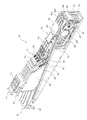
- FIG. 1 is a perspective view of the entire tape feeder in one embodiment of the present invention.
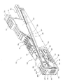
- FIG. 2 is a perspective view (No. 1) of the feeder body.
- FIG. 3 is a perspective view (part 2) of the feeder body.
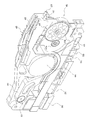
- FIG. 4 is a perspective view of the tape supplier.
- FIG. 5 is a perspective view (No. 1) showing the drive device for the cover tape feed gear and its peripheral portion.
- FIG. 6 is a perspective view (No. 2) showing the drive device for the cover tape feed gear and its peripheral portion.
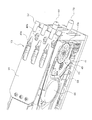
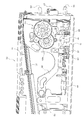
- FIG. 7 is a perspective view of the tip portion of the feeder body.
- FIG. 8 is a perspective view showing the front end portion of the feeder body with the front end cover plate removed.
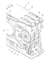
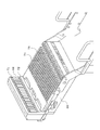
- FIG. 9 is a perspective view (No. 1) of two sprocket drive units.
- FIG. 1 is a perspective view (No. 1) of two sprocket drive units.
- FIG. 1 is a perspective view (No. 1) of two sprocket drive units.
- FIG. 1
- FIG. 10 is a perspective view (No. 2) of two sprocket drive units.
- FIG. 11 is a perspective view showing a state where the sprocket drive unit is removed from the feeder body.
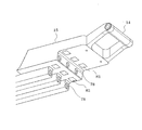
- FIG. 12 is a perspective view showing a structure for attaching the sprocket drive unit to the feeder body.
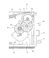
- FIG. 13 is a right side view showing the configuration of the device for driving the sprocket.
- FIG. 14 is a left side view showing the configuration of the device for driving the sprocket.
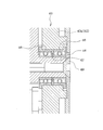
- FIG. 15 is an enlarged sectional view showing a structure in which each gear of the spur gear train is supported by a bearing.
- FIG. 16 is a perspective view of the feeder mounting table of the component mounting machine.
- FIG. 17 is a perspective view showing the configuration of the lower surface side of the operation panel of the feeder body.
- FIG. 18 is an enlarged perspective view of the handle portion of the tape supplier and its peripheral portion.
- FIG. 19 is a block diagram showing the configuration of the control system of the tape feeder.
- FIG. 20 is a flowchart showing the flow of processing of the automatic meshing operation control program.
- the tape feeder 11 is a conventional general tape feeder having a lateral width of the feeder body 13 (a tape feeder capable of setting only one component supply tape) so that a plurality of component supply tapes 12 can be set side by side in the horizontal width direction. It is formed to be approximately a plurality of times the horizontal width. In this embodiment, by reducing the interval between the adjacent component supply tapes 12, the width of the feeder main body 13 is, for example, approximately four times (approximately M times) the width of a conventional general tape feeder, and six ( N parts, where N is an integer greater than M) can be set side by side in the width direction.
- the component supply tape 12 stores components in component storage recesses formed in a line at a predetermined pitch on the carrier tape, and affixes a top tape (also called a cover tape) on the upper surface of the carrier tape. Sprocket holes (not shown) are formed in a line at a predetermined pitch along the side edge of the component supply tape 12.
- a handle 14 and an operation panel 15 are provided at the upper part of the rear side (removal direction side) of the feeder main body 13, and a reel holder for storing a tape reel 16 around which the component supply tape 12 is wound. 17 is provided.
- the reel holder 17 is formed so as to store a plurality of tape reels 16 arranged in two rows in the front and rear, and is stored so that each tape reel 16 can be rotated in the reel holder 17 as the component supply tape 12 is pulled out.
- the operation panel 15 is provided with operation keys for inputting various operation signals such as a tape supplier mounting work start signal for each sprocket drive unit 41 (each tape supplier 21) to be described later.
- the component supply tape 12 drawn from each tape reel 16 is supplied to the component suction position by the tape supplier 21.
- Each tape supplier 21 is configured to be detachably attached to the feeder body 13, and the width of each tape supplier 21 is the component supply so that only one component supply tape 12 is set in each tape supplier 21.
- the dimension is slightly larger than the width of the tape 12.
- a reel hooking portion 22 for holding the tape reel 16 on the tape supplier 21 removed from the feeder main body 13 is provided at the rear end portion of each tape supplier 21.
- the tape reel 16 can be hooked and held.
- the tape supplier 21 is provided with a cover tape peeling device 23 that peels off the cover tape that covers the upper surface of the component supply tape 12, and a cover tape collection case 24 that collects the cover tape peeled off from the component supply tape 12.
- the cover tape peeling device 23 includes a peeling roller 25, a tension roller 26, and a pair of cover tape feed gears 28 and 29. The cover tape peeled off by the peeling roller 25 is passed over the tension roller 26 and covered with the cover tape. It is sandwiched between the feed gears 28 and 29 and fed into the cover tape collecting case 24.
- the drive source of the cover tape feed gears 28 and 29 is provided on the feeder main body 13 side, and when the tape supplier 21 is attached to the feeder main body 13, one cover tape feed gear 28 is the drive gear 34 (see FIG. 5), the cover tape feed gears 28 and 29 are rotationally driven.
- a driving device 31 for driving the cover tape feeding gears 28 and 29 is provided above the space for mounting the tape supplier 21 in the feeder main body 13.
- the drive device 31 includes a motor 33 that rotationally drives a bevel gear 32 (see FIG. 6) and a drive gear 34 that is rotationally driven by the bevel gear 32, and the drive gear 34 is connected to one cover tape feed gear 28.
- the both cover tape feed gears 28 and 29 are rotationally driven by meshing.
- the motor 33, the bevel gear 32, and the drive gear 34 are provided in the same number as the number of tape suppliers 21 that can be mounted on the feeder main body 13, and the cover tape feed amount (peeling amount) is independently provided for each tape supplier 21. ) Can be controlled.
- the tape supplier 21 has a plurality of horizontal U-shaped tape holding portions 37 and 38 that hold only one side in the width direction of the component supply tape 12 on one side in the width direction of the component supply tape 12.
- the tape holding portions 37 and 38 are supplied to the parts so as to hold the parts supply tape 12 while meandering the parts supply tape 12 slightly in the width direction (or obliquely tilting).
- the component supply tape 12 can be held with a smaller width by being arranged little by little inward in the width direction of the tape 12.
- the same number of sprocket drive units 41 as the number of component supply tapes 12 that can be set on the feeder body 13 are arranged side by side in the width direction on the front end side of the feeder body 13.
- the sprocket drive mechanism 45 of each sprocket drive unit 41 is connected to the elevating lever 30 (see FIGS. 9, 10, and 12) via the sprocket 42 and the sprocket 42 via a spur gear train 43 (gear mechanism).
- the motor 44 and the like to be driven are assembled, and these move up and down integrally with the shaft 51 as a fulcrum.
- Each sprocket 42 is arranged at a position corresponding to each component supply tape 12 set in the feeder main body 13, and the sprocket 42 rotates to rotate the component while meshing the teeth of the sprocket 42 with the sprocket hole of each component supply tape 12.
- the supply tape 12 is pitch-fed toward the component suction position.
- each sprocket drive unit 41 In order to reduce the dimension in the width direction of each sprocket drive unit 41, the positions of the sprockets 42 of the two adjacent sprocket drive units 41 are shifted in the front-rear direction as shown in FIGS. By shifting the positions of the gears 43a of the spur gear train 43 of the two sprocket drive units 41, the empty space of each sprocket drive unit 41 is arranged with the gear 43a of the adjacent sprocket drive unit 41 protruding. It can be used effectively as a possible space.
- the sprocket drive mechanism 45 of each sprocket drive unit 41 uses a flat motor (DC servo motor, pulse motor, etc.) as the motor 44 for driving the sprocket 42, so that the rotation axis of the motor 44 is parallel to the axis of the sprocket 42. It is arranged so that the power of the motor 44 is transmitted to the sprocket 42 by the spur gear train 43.
- the upper cover plate 39 covering the upper part of the sprocket drive unit 41 in the feeder main body 13 is a component for sucking the component of the component supply tape 12 by the suction nozzle of the component mounting machine.
- the component suction openings 40a and 40b that open the suction positions are formed in a staggered pattern. In the present embodiment, since a total of six component supply tapes 12 can be mounted on the feeder main body 13, a total of six component suction openings 40a and 40b are formed.
- each gear 43 a of the spur gear train 43 and the sprocket 42 are rotatably supported by two bearings 46, and between the inner rings of the two bearings 46, an elastic material such as rubber and a spring washer is provided.
- the structure is configured such that an appropriate preload is applied to the bearing 46 by compressing the elastic member 47 by tightening a bearing retainer 48 that prevents the inner ring of the bearing 46 from slipping out by interposing the member 47.
- the elevating lever 30 assembled with the sprocket drive mechanism 45 of each sprocket drive unit 41 can move up and down the sprocket 42 side with the shaft 51 as a fulcrum on the unit base 50.
- the sprocket 42 is assembled and moved up and down between a meshing position where the teeth of the sprocket 42 mesh with the sprocket holes of the component supply tape 12 and a retracted position where the teeth of the sprocket 42 are located below the sprocket holes. ing.
- a guide pin 52 for guiding the vertical movement of the sprocket drive unit 41 is provided on the tip surface of each sprocket drive unit 41, and each guide pin 52 is fitted in each guide hole 53 (see FIG. 2) formed in the tip surface portion of the feeder body 13.
- each sprocket drive unit 41 is provided with a spring 55 (an elastic body such as a spring) as an urging means for urging the sprocket 42 side of the sprocket drive mechanism 45 upward with a shaft 51 as a fulcrum. ), And the sprocket drive mechanism 45 can be held at the meshing position, which is the upper limit position, by the elastic force of the spring 55.
- Each sprocket drive unit 41 is provided with a motor 56 as an actuator for lowering the sprocket drive mechanism 45 against the spring 55.
- Cams 57 are respectively fixed to the rotation shafts of the motors 56.
- each sprocket drive mechanism 45 has an L-shaped cam contact member 58 that contacts the cam 57 from below.
- the cam contact member 58 is integrated with the sprocket drive mechanism 45 against the spring 55. Pulled down, the sprocket drive mechanism 45 is held at the retracted position, which is the lower limit position.
- the sprocket drive mechanism 45 is moved by the elastic force of the spring 55 following the movement of the cam 57. Is pushed up and held at the fitting position which is the upper limit position. At this time, the sprocket drive mechanism 45 may be pushed up by the elastic force of the spring 55 by turning off the power to the motor 56 and releasing the driving force of the motor 56.
- a position detection dog 61 for detecting the position of the cam 57 is provided on the rotation shaft of each motor 56, and each position detection dog 61 is detected by each sprocket drive unit 41 correspondingly.
- a cam position sensor 62 (an optical sensor such as a photo interrupter or a non-contact type sensor such as a magnetic sensor) is provided, and each cam position sensor 62 changes the position of the cam 57 to a fitting position (uppermost position) / retracted position (lowermost position). ) Can be detected.
- each sprocket drive unit 41 has a mesh detection sensor 63 (photo interrupter or the like) as a mesh detection means for detecting that the sprocket 42 of the sprocket drive mechanism 45 has been raised to the mesh position.
- Non-contact sensors such as optical sensors and magnetic sensors).
- Each sprocket drive mechanism 45 is provided with a position detection dog 64 for detecting the meshing position, and the sprocket 42 teeth of any of the sprocket drive mechanisms 45 mesh with the sprocket holes of the component supply tape 12 to sprocket.
- the position detection dog 64 of the sprocket drive mechanism 45 is detected by the meshing detection sensor 63 and a detection signal is output.
- the mesh detection sensor 63 detects the position detection dog 64, and the minimum thickness component supply tape.
- the length of the teeth of the sprocket 42 and the positions of the mesh detection sensor 63 and the position detection dog 64 are set so that the mesh detection sensor 63 does not detect the position detection dog 64 when the teeth of the sprocket 42 are not meshed with the 12 sprocket holes. Is set.
- a connector 67 for connecting a signal line and a power line of the feeder main body 13 to a connector 68 (see FIG. 16) of the feeder mounting table 66 of the component mounting machine and two positioning pins are provided on the front end surface of the feeder main body 13.
- 69 and 70 are provided, and the two positioning pins 69 and 70 are inserted into the positioning holes 71 and 72 (see FIG. 16) of the feeder mounting table 66 of the component mounting machine, so that the feeder main body 13 is mounted on the feeder mounting table 66.
- the attachment position is positioned, and the connector 67 of the feeder body 13 is inserted and connected to the connector 68 of the feeder mounting table 66.
- a guide groove 74 having an inverted T-shaped cross section for supporting the tape feeder 11 in a vertical position is provided on the upper surface of the feeder mounting table 66, and a guide rail having an inverted T-shaped cross section provided on the lower surface side of the feeder body 13. (Not shown) is inserted into the guide groove 74 from the front side, so that the tape feeder 11 is supported in a vertically placed state on the feeder mounting table 66 and a clamp member (not shown) provided on the feeder main body 13. ) Fits into the clamp groove 79 of the feeder mounting table 66 and presses the feeder main body 13 forward (to the connector 68 side of the feeder mounting table 66) to clamp the feeder main body 13 on the feeder mounting table 66. Positioned in the front-rear direction and detachably attached.
- a handle portion 76 is provided at the rear upper end of the cover tape collecting case 24 of each tape supplier 21, and a positioning pin 77 (see FIG. 18) is provided at the front end portion of each handle portion 76.
- a positioning hole 78 is formed in the lower step portion of the operation panel 15 of the feeder main body 13, and when the tape supplier 21 is set in the feeder main body 13, The handle 76 is positioned with respect to the lower surface of the operation panel 15 by inserting the positioning pins 77 into the positioning holes 78 on the lower side of the operation panel 15.
- an RF tag 81 (electronic tag, IC tag, radio wave) that is a supplier identification information storage unit that stores identification information (hereinafter referred to as “supplier ID”) of the tape supplier 21 is provided on the upper surface of the handle portion 76.
- Tag also called a wireless tag.
- the RF tag 81 may store component information of the component supply tape 12 in addition to the supplier ID or instead of the supplier ID.
- a reader 82 (see FIG. 17), which is identification information reading means for reading the supplier ID stored in the RF tag 81, is provided on the lower surface of the operation panel 15 of the feeder body 13, and the feeder body
- the RF tag 81 on the upper surface of the handle portion 76 is placed on the lower surface of the operation panel 15.
- the supplier ID stored in the RF tag 81 facing the reader 82 in the vicinity is read by the reader 82.
- the signal of the supplier ID output from the reader 82 is also used as a set confirmation signal for the tape supplier 21 to the feeder main body 13.
- the tape supplier 21 is set to the feeder main body 13. Is to check.
- the reader 82 disposed on the lower surface side of the operation panel 15 only needs to be provided with at least the antenna of the reader 82, and the control circuit unit of the reader 82 is separated from the antenna and disposed in another part. Also good.
- the feeder main body 13 is provided with a control device 84 for controlling the operation of the motors 33, 44, 56 and the like.
- the control device 84 has a communication function (communication means), and the supplier ID read by the reader 82 is transmitted to the control device 84, and the control device 85 of the component mounter is connected from the control device 84 via the connectors 67 and 68. Sent to.
- the memory 86 (feeder body identification information storage means) of the control device 84 of the feeder body 13 stores identification information of the feeder body 13 (hereinafter referred to as “feeder body ID”). To the control device 85 of the component mounting machine via the connectors 67 and 68.
- Each sprocket drive unit 41 is also provided with an ID storage memory 87 that stores identification information of the sprocket drive unit 41 (hereinafter referred to as “sprocket drive unit ID”), and the controller 84 of the feeder body 13 controls each sprocket drive.
- the sprocket drive unit ID stored in the ID storage memory 87 of the unit 41 is read and transmitted to the control device 85 of the component mounting machine.
- the control device 85 of the component mounting machine can individually manage the tape supplier 21, the feeder body 13, and the sprocket drive unit 41 using the supplier ID, the feeder body ID, and the sprocket drive unit ID.
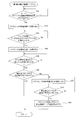
- the control device 84 of the feeder main body 13 automatically lowers the sprocket 42 to the retracted position when the tape supplier 21 is set on the feeder main body 13 by executing an automatic meshing operation control program shown in FIG. After the component supply tape 12 is set above the sprocket 42, the sprocket drive mechanism unit vertical movement motor 56 is controlled so as to raise the sprocket 42 to the meshing position, and control to raise the sprocket 42 to the meshing position is performed.
- the automatic meshing operation control program of FIG. 20 is repeatedly executed for each sprocket drive unit 41 (each tape supplier 21) during the power-on period of the control device 84 of the feeder main body 13.
- step 101 it is first determined in step 101 whether or not a tape supplier mounting work start signal has been input (whether or not the operator has operated the mounting work start key on the operation panel 15). If the tape supplier mounting work start signal is not input, the process waits until the tape supplier mounting work start signal is input.
- step 102 the vertical movement motor 56 of the sprocket drive mechanism section is operated to lower the sprocket drive mechanism section 45 against the spring 55 to lower the sprocket 42 to the retracted position.
- step 103 whether or not the operator has completed the work of mounting the tape supplier 21 on the feeder body 13 depending on whether or not the reader 82 of the feeder body 13 has read the supplier ID from the RF tag 81 of the tape supplier 21. (Whether the RF tag 81 of the tape supplier 21 faces the reader 82 of the feeder body 13), and if the reader 82 of the feeder body 13 has not yet read the supplier ID, it waits until the supplier ID is read. .
- Step 104 when the reader 82 of the feeder main body 13 reads the supplier ID from the RF tag 81 of the tape supplier 21, it is determined that the operator has completed the operation of mounting the tape supplier 21 to the feeder main body 13, and the process proceeds to Step 104.
- the sprocket drive mechanism part vertical movement motor 56 is rotated to the original position and the cam 57 is returned to the uppermost position (or a position in the vicinity thereof). After the sprocket drive mechanism 45 is raised to the fitting position by force, the power supply to the motor 56 is turned off.
- step 105 it is determined whether or not the cam position sensor 62 has detected that the cam 57 has returned to the vicinity of the fitting position (uppermost position). If not, the system waits until the cam 57 returns to the vicinity of the fitting position (uppermost position).
- step 106 a detection signal is received from the meshing detection sensor 63. It is determined whether or not the teeth of the sprocket 42 are engaged with the sprocket holes of the component supply tape 12 based on whether or not they are output, and if the detection signal is output from the engagement detection sensor 63, the teeth of the sprocket 42 are detected. It is determined that the 12 sprocket holes are engaged, and the automatic engagement operation is terminated. At this time, the sprocket 42 may be appropriately rotated so that the leading component of the component supply tape 12 is positioned with respect to the component supply position.
- step 106 determines whether a detection signal is output from the engagement detection sensor 63, it is determined that the teeth of the sprocket 42 are not yet engaged with the sprocket holes of the component supply tape 12, Proceeding to step 107, the motor 44 is reversely rotated to reversely rotate the sprocket 42 by a predetermined angle, and then the process proceeds to step 108, where it is determined whether a detection signal is output from the meshing detection sensor 63, and the detection signal is output.
- step 107 it is determined that the teeth of the sprocket 42 are not yet engaged with the sprocket holes of the component supply tape 12, and the process returns to step 107 to reversely rotate the motor 44 and reversely rotate the sprocket 42 by a predetermined angle. repeat.
- the process of rotating the sprocket 42 reversely by a predetermined angle by the motor 44 is repeated, and when the detection signal is output from the mesh detection sensor 63, the sprocket 42 teeth.
- step 109 where the motor 44 is rotated forward to rotate the sprocket 42 forward, and the leading component of the component supply tape 12 is moved relative to the component supply position. After positioning, the automatic meshing operation is completed.
- the RF tag 81 storing the supplier ID is provided in the tape supplier 21, and the reader 82 that reads the supplier ID from the RF tag 81 of the tape supplier 21 attached to the feeder body 13 is provided in the feeder body. 13, the reader 82 provided in the feeder main body 13 can automatically read the supplier ID of the tape supplier 21 attached to the feeder main body 13. Can solve the problem.
- the supplier ID signal obtained by reading the supplier ID from the RF tag 81 of the tape supplier 21 by the reader 82 of the feeder main body 13 also serves as a signal for confirming the mounting of the tape supplier 21.
- the RF tag 81 may be used only as a mounting confirmation sensor.
- the feeder main body ID is stored in the memory 86 of the feeder main body 13, and the feeder main body ID read from the memory 86 and the supplier ID read by the reader 82 are transmitted to the component mounting machine side on which the feeder main body 13 is mounted. Therefore, both the feeder body ID and the supplier ID can be managed on the component mounter side.
- the feeder main body 13 is configured such that a plurality of tape suppliers 21 are detachably mounted independently, and the feeder main body 13 includes a plurality of feeders corresponding to the plurality of tape suppliers 21 to be mounted.
- the sprocket drive unit 41 is provided, and each sprocket drive unit 41 is provided with an ID storage memory 87 storing the sprocket drive unit ID, and the sprocket drive unit ID read from the ID storage memory 87 of the plurality of sprocket drive units 41 is stored. Since the transmission is made to the component mounter side, the sprocket drive unit ID can be managed on the component mounter side in addition to the supplier ID and the feeder main body ID.
- the sprocket 42 when the tape supplier 21 is set in the feeder body 13, the sprocket 42 is lowered to the retracted position and the component supply tape 12 is set above the sprocket 42, and then the sprocket 42 is raised to the meshing position. If the detection signal is not output from the mesh detection sensor 63 because the teeth of the sprocket 42 do not mesh with the sprocket holes of the component supply tape 12 even if the control is performed, the sprocket 42 is rotated so that the teeth of the sprocket 42 become the component supply tape.
- the rotation direction of the sprocket 42 during the automatic meshing operation may be either forward rotation or reverse rotation, but the teeth of the sprocket 42 mesh with the sprocket holes of the component supply tape 12 during the automatic meshing operation. Even if the sprocket 42 is not in contact, the sprocket 42 rotates while the teeth of the sprocket 42 hit the lower surface of the sprocket 42, so that the sprocket 42 moves in the rotational direction of the sprocket 42. If this is done, the leading component of the component supply tape 12 may pass through the component suction position and become useless (cannot be sucked by the suction nozzle).
- the sprocket 42 is reversely rotated so that the teeth of the sprocket 42 mesh with the sprocket holes of the component supply tape 12 and the detection signal is output from the mesh detection sensor 63. Since the component supply tape 12 is positioned by rotating the sprocket 42 forward, the leading component of the component supply tape 12 can be prevented from passing over the component adsorption position during the automatic meshing operation. After confirming that the sprocket hole of the component supply tape 12 is engaged, the leading component of the component supply tape 12 can be positioned so as to be positioned at the component suction position.
- the tape reel 16 and the tape supplier 21 are configured to be detachably attached to the feeder main body 13, so that when the component supply tape 12 is replaced, the feeder main body 13 is attached to the component mounting machine. After the tape reel 16 and the tape supplier 21 are removed from the feeder main body 13 in the state of being attached, the component supply tape 12 pulled out from the new tape reel 16 is held by the tape supplier 21, and these are supplied to the feeder.
- the teeth of the sprocket 42 can be automatically meshed with the sprocket holes of the component supply tape 12 by the automatic meshing operation, and the replacement work of the component supply tape 12 can be easily performed.
- the feeder main body 13 is provided with a plurality of sprocket drive units 41, and a plurality of tape suppliers 21 are detachably attached to the feeder main body 13 and supplied to the respective tape suppliers 21. Since the teeth of the sprocket 42 of each sprocket drive unit 41 are engaged with the sprocket holes of the component supply tape 12, a plurality of components supplied to the feeder main body 13 attached to the feeder mounting table 66 of the component mounting machine are supplied. Of the tapes 12, there is an advantage that only the component supply tape 12 that has run out of components can be removed from the feeder body 13 together with the tape supplier 21 and replaced with a new component supply tape 12.
- the present invention may be configured such that only one sprocket drive unit 41 is provided in the feeder main body 13 and only one tape supplier 21 is detachably attached to the feeder main body 13.
- the feeder main body 13 is provided with the reel holder 17 for collectively storing a plurality of tape reels 16.
- each tape supplier 21 is provided with a reel holder for storing one tape reel 16. It is good also as a composition.
- the present invention is not limited to the above-described embodiments.
- the number of tape suppliers 21 (the number of sprocket drive units 41) that can be mounted on the feeder body 13 is changed, or the sprocket drive mechanism is slid in the vertical direction.
- various modifications can be made without departing from the scope of the invention, such as a configuration in which the object is moved.
- sprocket drive mechanism 46 ... bearing, 47 ... elastic member, 48 ... bearing retainer, 49 ... screw, 51 ... shaft 52 ... guide pin 53 ... guide hole 55 ... spring (biasing means) 56 ... motor (actuator) 57 ... cam, 58 ... cam contact member, 61 ... position detection dog, 62 ... cam position sensor, 63 ... mesh detection sensor (mesh detection means), 64 ... position detection dog, 66 ... feeder mounting table, 67, 68 ... connector, 69, 70 ... positioning pin, 71, 72 ... positioning hole, 74 ... guide groove, 76 ... handle part, 77 ... positioning pin, 78 ... positioning hole, 81 ... RF tag (supplier identification information storage means) , 82 ... Reader (identification information reading storage means), 84 ... Feeder body control device (communication means), 85 ... Component mounter control device, 86 ... Memory, 87 ... ID storage memory
Landscapes
- Engineering & Computer Science (AREA)
- Manufacturing & Machinery (AREA)
- Microelectronics & Electronic Packaging (AREA)
- Operations Research (AREA)
- Supply And Installment Of Electrical Components (AREA)
Priority Applications (2)
| Application Number | Priority Date | Filing Date | Title |
|---|---|---|---|
| CN201280065721.XA CN104025731B (zh) | 2011-11-01 | 2012-10-10 | 带式供料器 |
| EP12846259.5A EP2775811B1 (en) | 2011-11-01 | 2012-10-10 | Tape feeder |
Applications Claiming Priority (2)
| Application Number | Priority Date | Filing Date | Title |
|---|---|---|---|
| JP2011-240134 | 2011-11-01 | ||
| JP2011240134A JP5846630B2 (ja) | 2011-11-01 | 2011-11-01 | テープフィーダ |
Publications (1)
| Publication Number | Publication Date |
|---|---|
| WO2013065458A1 true WO2013065458A1 (ja) | 2013-05-10 |
Family
ID=48191816
Family Applications (1)
| Application Number | Title | Priority Date | Filing Date |
|---|---|---|---|
| PCT/JP2012/076181 Ceased WO2013065458A1 (ja) | 2011-11-01 | 2012-10-10 | テープフィーダ |
Country Status (4)
| Country | Link |
|---|---|
| EP (1) | EP2775811B1 (enExample) |
| JP (1) | JP5846630B2 (enExample) |
| CN (1) | CN104025731B (enExample) |
| WO (1) | WO2013065458A1 (enExample) |
Cited By (2)
| Publication number | Priority date | Publication date | Assignee | Title |
|---|---|---|---|---|
| WO2015040079A1 (en) * | 2013-09-18 | 2015-03-26 | Mycronic AB | Method, system and device for impoved storage and handling of components |
| JP2018046313A (ja) * | 2017-12-27 | 2018-03-22 | 富士機械製造株式会社 | フィーダ、および部品実装装置 |
Families Citing this family (13)
| Publication number | Priority date | Publication date | Assignee | Title |
|---|---|---|---|---|
| JP6176837B2 (ja) * | 2013-05-28 | 2017-08-09 | 富士機械製造株式会社 | 部品実装機及び生産ラインのフィーダセット確認システム |
| JP6153611B2 (ja) * | 2013-06-24 | 2017-06-28 | 富士機械製造株式会社 | 部品実装装置 |
| JP6143865B2 (ja) * | 2013-06-24 | 2017-06-07 | 富士機械製造株式会社 | フィーダ制御装置 |
| JP6097937B2 (ja) * | 2014-01-27 | 2017-03-22 | パナソニックIpマネジメント株式会社 | 部品照合方法および部品照合システム |
| JP6097938B2 (ja) * | 2014-01-27 | 2017-03-22 | パナソニックIpマネジメント株式会社 | 部品照合方法および部品照合システム |
| JP6276397B2 (ja) * | 2014-05-08 | 2018-02-07 | 富士機械製造株式会社 | 部品実装システム |
| WO2016063369A1 (ja) * | 2014-10-22 | 2016-04-28 | 富士機械製造株式会社 | 部品実装システムおよびフィーダ |
| CN107006140B (zh) * | 2014-11-17 | 2019-07-26 | 株式会社富士 | 带式供料器以及元件安装机 |
| WO2018008144A1 (ja) * | 2016-07-08 | 2018-01-11 | 富士機械製造株式会社 | フィーダ |
| WO2019111344A1 (ja) * | 2017-12-06 | 2019-06-13 | ヤマハ発動機株式会社 | 部品実装機、部品供給リール駆動方法 |
| JP2019117822A (ja) * | 2017-12-26 | 2019-07-18 | パナソニックIpマネジメント株式会社 | リール保持装置およびリール押え部材 |
| JP7129610B2 (ja) * | 2018-03-30 | 2022-09-02 | パナソニックIpマネジメント株式会社 | 部品供給ユニットの配置決定方法および部品供給ユニットの配置決定装置 |
| JP6986148B2 (ja) * | 2018-05-25 | 2021-12-22 | 株式会社Fuji | 部品実装システム |
Citations (6)
| Publication number | Priority date | Publication date | Assignee | Title |
|---|---|---|---|---|
| JP2002533944A (ja) * | 1998-12-22 | 2002-10-08 | マイデータ オートメーション アクチボラグ | 部品テープ情報を部品取付機に移転する方法および手段 |
| JP2005503677A (ja) * | 2001-09-19 | 2005-02-03 | マイデータ オートメーション アクチボラグ | コンポーネント装着機でコンポーネントを扱うシステム |
| JP2008130851A (ja) * | 2006-11-21 | 2008-06-05 | Fuji Mach Mfg Co Ltd | フィーダの作業用アタッチメント |
| JP2010040901A (ja) * | 2008-08-07 | 2010-02-18 | Panasonic Corp | 電子部品供給用フィーダ、電子部品実装装置およびrfid管理システム |
| JP2010109109A (ja) | 2008-10-30 | 2010-05-13 | Fuji Mach Mfg Co Ltd | テープフィーダ |
| JP2011138834A (ja) | 2009-12-26 | 2011-07-14 | Fuji Mach Mfg Co Ltd | 電子回路部品供給装置 |
Family Cites Families (3)
| Publication number | Priority date | Publication date | Assignee | Title |
|---|---|---|---|---|
| JP4065491B2 (ja) * | 2001-02-19 | 2008-03-26 | キヤノン株式会社 | ユニット、及び画像処理装置 |
| SE522521C2 (sv) * | 2001-09-07 | 2004-02-10 | Mydata Automation Ab | Förfarande, system och arrangemang för hantering av komponenttejper |
| WO2006126465A1 (en) * | 2005-05-23 | 2006-11-30 | Matsushita Electric Industrial Co., Ltd. | Electronic components carrier tape package and electronic components feeding apparatus |
-
2011
- 2011-11-01 JP JP2011240134A patent/JP5846630B2/ja active Active
-
2012
- 2012-10-10 EP EP12846259.5A patent/EP2775811B1/en active Active
- 2012-10-10 CN CN201280065721.XA patent/CN104025731B/zh active Active
- 2012-10-10 WO PCT/JP2012/076181 patent/WO2013065458A1/ja not_active Ceased
Patent Citations (6)
| Publication number | Priority date | Publication date | Assignee | Title |
|---|---|---|---|---|
| JP2002533944A (ja) * | 1998-12-22 | 2002-10-08 | マイデータ オートメーション アクチボラグ | 部品テープ情報を部品取付機に移転する方法および手段 |
| JP2005503677A (ja) * | 2001-09-19 | 2005-02-03 | マイデータ オートメーション アクチボラグ | コンポーネント装着機でコンポーネントを扱うシステム |
| JP2008130851A (ja) * | 2006-11-21 | 2008-06-05 | Fuji Mach Mfg Co Ltd | フィーダの作業用アタッチメント |
| JP2010040901A (ja) * | 2008-08-07 | 2010-02-18 | Panasonic Corp | 電子部品供給用フィーダ、電子部品実装装置およびrfid管理システム |
| JP2010109109A (ja) | 2008-10-30 | 2010-05-13 | Fuji Mach Mfg Co Ltd | テープフィーダ |
| JP2011138834A (ja) | 2009-12-26 | 2011-07-14 | Fuji Mach Mfg Co Ltd | 電子回路部品供給装置 |
Non-Patent Citations (1)
| Title |
|---|
| See also references of EP2775811A4 * |
Cited By (9)
| Publication number | Priority date | Publication date | Assignee | Title |
|---|---|---|---|---|
| WO2015040079A1 (en) * | 2013-09-18 | 2015-03-26 | Mycronic AB | Method, system and device for impoved storage and handling of components |
| WO2015040082A3 (en) * | 2013-09-18 | 2015-06-18 | Mycronic AB | Method, system and device for providing information to an smt system operator |
| CN106031323A (zh) * | 2013-09-18 | 2016-10-12 | 迈康尼股份公司 | 用于组件的改进的存储和处理的方法、系统和设备 |
| JP2019140405A (ja) * | 2013-09-18 | 2019-08-22 | マイクロニック アーベーMycronic Ab | 部品の保管および取扱を改良した方法、システムおよび装置 |
| CN106031323B (zh) * | 2013-09-18 | 2020-03-17 | 迈康尼股份公司 | 用于组件的改进的存储和处理的方法、系统和设备 |
| US10640290B2 (en) | 2013-09-18 | 2020-05-05 | Mycronic AB | Method, system and device for providing information to an SMT system operator |
| CN111465309A (zh) * | 2013-09-18 | 2020-07-28 | 迈康尼股份公司 | 用于组件的改进的存储和处理的方法、系统和设备 |
| CN111465309B (zh) * | 2013-09-18 | 2021-11-30 | 迈康尼股份公司 | 用于组件的改进的存储和处理的方法、系统和设备 |
| JP2018046313A (ja) * | 2017-12-27 | 2018-03-22 | 富士機械製造株式会社 | フィーダ、および部品実装装置 |
Also Published As
| Publication number | Publication date |
|---|---|
| CN104025731B (zh) | 2016-08-17 |
| JP5846630B2 (ja) | 2016-01-20 |
| JP2013098375A (ja) | 2013-05-20 |
| EP2775811B1 (en) | 2017-05-10 |
| CN104025731A (zh) | 2014-09-03 |
| EP2775811A1 (en) | 2014-09-10 |
| EP2775811A4 (en) | 2015-06-03 |
Similar Documents
| Publication | Publication Date | Title |
|---|---|---|
| JP5846630B2 (ja) | テープフィーダ | |
| JP5797087B2 (ja) | テープフィーダ | |
| JP5748284B2 (ja) | テープフィーダ | |
| JP5777800B2 (ja) | テープフィーダ | |
| JP5758541B2 (ja) | 部品実装機のフィーダ管理システム | |
| JP2013098375A5 (enExample) | ||
| JP6417426B2 (ja) | テープフィーダ | |
| JP6276398B2 (ja) | テープフィーダ | |
| JP6143865B2 (ja) | フィーダ制御装置 | |
| JP4938607B2 (ja) | 部品供給装置及び部品供給装置におけるサプレッサの開放状態の判定方法 | |
| JP6586620B2 (ja) | フィーダ | |
| JP6762126B2 (ja) | カバーテープ引きこみ装置 | |
| JP2010080748A (ja) | 電子部品供給カセット、電子部品供給カート及び電子部品装着装置 |
Legal Events
| Date | Code | Title | Description |
|---|---|---|---|
| 121 | Ep: the epo has been informed by wipo that ep was designated in this application |
Ref document number: 12846259 Country of ref document: EP Kind code of ref document: A1 |
|
| REEP | Request for entry into the european phase |
Ref document number: 2012846259 Country of ref document: EP |
|
| WWE | Wipo information: entry into national phase |
Ref document number: 2012846259 Country of ref document: EP |
|
| NENP | Non-entry into the national phase |
Ref country code: DE |