WO2013061997A1 - タービン動翼及びこれを備えたガスタービン - Google Patents
タービン動翼及びこれを備えたガスタービン Download PDFInfo
- Publication number
- WO2013061997A1 WO2013061997A1 PCT/JP2012/077455 JP2012077455W WO2013061997A1 WO 2013061997 A1 WO2013061997 A1 WO 2013061997A1 JP 2012077455 W JP2012077455 W JP 2012077455W WO 2013061997 A1 WO2013061997 A1 WO 2013061997A1
- Authority
- WO
- WIPO (PCT)
- Prior art keywords
- plug
- recess
- rotor
- blade
- turbine
- Prior art date
Links
Images


Classifications
-
- F—MECHANICAL ENGINEERING; LIGHTING; HEATING; WEAPONS; BLASTING
- F01—MACHINES OR ENGINES IN GENERAL; ENGINE PLANTS IN GENERAL; STEAM ENGINES
- F01D—NON-POSITIVE DISPLACEMENT MACHINES OR ENGINES, e.g. STEAM TURBINES
- F01D25/00—Component parts, details, or accessories, not provided for in, or of interest apart from, other groups
- F01D25/08—Cooling; Heating; Heat-insulation
- F01D25/12—Cooling
-
- F—MECHANICAL ENGINEERING; LIGHTING; HEATING; WEAPONS; BLASTING
- F01—MACHINES OR ENGINES IN GENERAL; ENGINE PLANTS IN GENERAL; STEAM ENGINES
- F01D—NON-POSITIVE DISPLACEMENT MACHINES OR ENGINES, e.g. STEAM TURBINES
- F01D5/00—Blades; Blade-carrying members; Heating, heat-insulating, cooling or antivibration means on the blades or the members
- F01D5/12—Blades
- F01D5/22—Blade-to-blade connections, e.g. for damping vibrations
- F01D5/225—Blade-to-blade connections, e.g. for damping vibrations by shrouding
-
- F—MECHANICAL ENGINEERING; LIGHTING; HEATING; WEAPONS; BLASTING
- F01—MACHINES OR ENGINES IN GENERAL; ENGINE PLANTS IN GENERAL; STEAM ENGINES
- F01D—NON-POSITIVE DISPLACEMENT MACHINES OR ENGINES, e.g. STEAM TURBINES
- F01D5/00—Blades; Blade-carrying members; Heating, heat-insulating, cooling or antivibration means on the blades or the members
- F01D5/12—Blades
- F01D5/14—Form or construction
- F01D5/18—Hollow blades, i.e. blades with cooling or heating channels or cavities; Heating, heat-insulating or cooling means on blades
- F01D5/187—Convection cooling
-
- F—MECHANICAL ENGINEERING; LIGHTING; HEATING; WEAPONS; BLASTING
- F05—INDEXING SCHEMES RELATING TO ENGINES OR PUMPS IN VARIOUS SUBCLASSES OF CLASSES F01-F04
- F05D—INDEXING SCHEME FOR ASPECTS RELATING TO NON-POSITIVE-DISPLACEMENT MACHINES OR ENGINES, GAS-TURBINES OR JET-PROPULSION PLANTS
- F05D2260/00—Function
- F05D2260/20—Heat transfer, e.g. cooling
- F05D2260/202—Heat transfer, e.g. cooling by film cooling
Definitions
- the present invention relates to a turbine rotor blade and a gas turbine including the same.
- a tip shroud is arranged at the tip of the blade body that constitutes each turbine rotor blade, and the occurrence of unstable vibration modes is suppressed by increasing the structural damping. Since the tip shroud needs to be cooled as the temperature of the gas turbine increases, a cooling structure is formed in the tip shroud.
- a cavity communicating with a cooling path in the blade body is provided in the chip shroud so that the cooling air that has cooled the blade body can also be used for cooling the chip shroud.
- the cavity is formed by forming a recess in the chip shroud communicating with the cooling path and closing the opening of the recess with a plug.
- Patent Document 2 in order to prevent the plug from being detached due to the centrifugal force due to the rotation of the rotor, a mounting groove is formed on each of the pair of side surfaces of the recess, and the plug is inserted into the mounting groove, thereby forming the recess.
- a technique is described in which a cavity is formed by closing the opening. More specifically, the mounting groove of Patent Document 2 is formed so as to face the rotor in the axial direction, and the opening is closed by inserting a single plug into the mounting groove from the circumferential direction. It is like that.
- Patent Document 2 has a problem that a portion of the plug that is not inserted into the mounting groove swells outward in the radial direction of the rotor due to centrifugal force. That is, the pair of mounting grooves are opposed to each other in the axial direction of the rotor and the mounting grooves are spaced apart from each other to some extent, so that the central portion of the plug is radially outward due to the centrifugal force acting on the plug and the pressure difference inside and outside the cavity. It becomes easy to creep deformation. Therefore, due to the swelling of the plug itself based on this creep deformation, the durability of the plug may be reduced when used for a long period of time.
- the present invention has been made in view of such problems, and an object of the present invention is to provide a turbine rotor blade capable of improving the durability of a plug and a gas turbine including the turbine rotor blade.
- a turbine blade according to the present invention includes a blade body attached to the rotor body so as to extend radially outward of the rotor body from the rotor body, and a tip shroud fixed to the radially outer side of the blade body.
- a cooling passage extending in a radial direction of the rotor main body and through which a cooling medium flows is formed in the blade main body, and the tip shroud opens outward in the radial direction, and
- a plurality of plugs that cooperate with each other to close the openings of the recesses by being inserted into a shroud main body having a recess communicating with the cooling path formed on the outer peripheral end surface and an attachment groove formed on a side surface of the recess.
- a plug having a piece.
- the plug is formed by a plurality of plug pieces, and each plug piece is inserted into the mounting groove, so that the swelling is reduced as compared with the case where the plug is configured as a single piece. be able to.
- the concave portion extends in the direction along the outer peripheral end surface as a longitudinal direction, the mounting groove is formed on the pair of side surfaces along the longitudinal direction, and the plurality of plug pieces are in contact with each other. It is preferable that the openings of the recesses are closed side by side in the longitudinal direction.
- the mounting grooves are formed on the pair of side surfaces along the longitudinal direction of the recess, the facing direction of the pair of side surfaces is the short direction of the recess. Therefore, the distance between the pair of mounting grooves is set narrower than when the mounting grooves are formed on the side surfaces along the short direction of the recesses. As a result, the gap in the opposing direction of the mounting groove in the plug piece inserted into the mounting groove can also be set narrow, so that deformation of the plug piece due to centrifugal force can be reduced, and the swelling of the plug piece can be further increased. This can be further reduced.
- a plurality of the cooling paths are formed inside the blade body, and radially outer ends of the plurality of cooling paths are arranged in directions inclined respectively in a circumferential direction and an axial direction of the rotor body, It is preferable that the recess extends with the arrangement direction of radially outer ends of the plurality of cooling paths as the longitudinal direction.
- the longitudinal direction of the recess extends in a direction inclined in the circumferential direction and the axial direction, for example, there is an obstacle when inserting the plug piece on the outer peripheral end surface of the chip shroud.
- the plug piece can be easily inserted into the mounting groove. Further, it is possible to prevent the plug piece from being detached due to the rotational acceleration of the rotor.
- the shroud body has a plug insertion port for inserting the plug piece into the mounting groove on at least one end side in the longitudinal direction of the recess.
- the plug piece can be easily and reliably inserted into the mounting groove.
- the shroud main body has a plurality of chip fins that protrude from the outer peripheral end surface, extend in the circumferential direction of the rotor main body, and are spaced from each other in the axial direction of the rotor main body. Preferably, it is formed between the plurality of chip fins.
- the chip fins are less likely to become obstacles because the plug is composed of a plurality of plug pieces. Can be inserted into the mounting groove.
- the plug piece can be more easily inserted into the mounting groove even when the chip fin is present.
- a gas turbine according to the present invention includes the rotor main body to which any one of the turbine rotor blades described above is attached, and a casing that rotatably covers the rotor main body. Since the gas turbine having such characteristics includes the above-described turbine rotor blade, the swelling of the plug can be reduced.
- the plug is divided into the plug pieces, the swelling based on the centrifugal force can be reduced, and the durability of the plug can be improved.
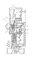
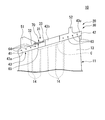
- FIG. 1 is an overall view of a gas turbine according to an embodiment of the present invention. It is the figure which looked at the turbine rotor blade of the gas turbine which concerns on embodiment of this invention from the circumferential direction of the rotor. It is the figure which looked at the turbine rotor blade of the gas turbine which concerns on embodiment of this invention from the radial direction outer side of the rotor. It is the figure which looked at the shroud main body from the radial direction outer side of the rotor.
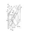
- FIG. 4 is a sectional view taken along line AA in FIG. 3. It is a figure explaining the procedure which inserts a plug piece in a mounting groove, and is a figure just before inserting a 1st plug piece.
- a gas turbine 1 includes a compressor 3 that generates compressed air, a combustor 4 that generates fuel gas G by supplying fuel to the compressed air supplied from the compressor 3, and a combustor. 4 and a turbine 5 that is rotationally driven by the combustion gas G supplied from 4.
- the compressor 3 includes a compressor casing 3a that rotatably covers the rotor body 2, a plurality of compressor blades 3b that are fixed to the rotor body 2 and arranged in an annular shape, and an annular arrangement that is supported by the compressor casing 3a. And a plurality of compressor stationary blades 3c.
- the compressor rotor blades 3b and the compressor stationary blades 3c are alternately arranged in a plurality of stages in the direction of the axis O of the rotor.
- the turbine 5 rotatably covers the rotor body 2 and includes a turbine casing 5a having a combustion gas flow path F therein, a plurality of turbine blades 10 fixed to the rotor body 2 and arranged in an annular shape, and a turbine casing. And a plurality of turbine stationary blades 5b arranged in an annular shape supported by 5a.
- the turbine blades 10 and the turbine stationary blades 5 b are alternately arranged in a plurality of stages in the direction of the axis O of the rotor body 2.
- the radial direction of the rotor body 2 is simply referred to as “radial direction”
- the circumferential direction of the rotor body 2 is simply referred to as “circumferential direction”
- the axis O direction of the rotor body 2 is simply referred to as “axis line O”. It is called “direction”.
- the turbine rotor blade 10 includes a blade body 11 disposed in the combustion gas flow path F in FIG. 1, and a tip shroud 20 fixed to the radially outer side of the blade body 11. .
- a platform provided so as to protrude from the wing body 11 and a blade root projecting further radially inward from the platform are provided. Yes.
- the turbine rotor blade 10 is integrally fixed to the rotor body 2.
- the blade main body 11 is provided so as to extend from the rotor main body 2 toward the radially outer side of the rotor main body 2. Further, as shown in FIG. 3, the blade body 11 has a circumferential one side (rotational direction of the rotor body 2) from the leading edge on the upstream side of the combustion gas flow path to the trailing edge on the downstream side along the axis O direction. It has a blade-shaped cross section in which a pressure surface 12 and a suction surface 13 are formed so as to be convex toward the front side, the lower side of FIGS. 3 and 4. This cross-sectional shape is the other side in the circumferential direction (the rear side in the rotational direction of the rotor body 2, the upper side in FIGS.
- a plurality of (six in this embodiment) cooling passages 14 extending in the radial direction are formed inside the blade body 11.
- the cooling passages 14 are formed at intervals from each other, for example, so as to be arranged along the direction along the center line, that is, along the extending direction of the cross-sectional shape of the blade body 11.
- Cooling air (cooling medium) supplied from the radially inner side of the blade body 11 circulates in the cooling path 14 toward the radially outer side.
- the tip shroud 20 includes a shroud body 30 provided integrally with the wing body 11 and a plug 70 that is detachably attached to the shroud body 30.
- the shroud body 30 is formed in a plate shape having a predetermined thickness in the radial direction, and protrudes in the circumferential direction on the radially outer side of the wing body 11 with respect to the wing body 11. Are fixed together.
- a surface of the shroud main body 30 facing outward in the radial direction is an outer peripheral end surface 31 of the shroud main body 30.
- an upstream end surface 41 is a surface that faces one side in the axis O direction (the upstream side of the gas flow path, the left side in FIGS. 2 to 4) that extends upstream and extends in the circumferential direction.
- a surface that faces the other side in the axis O direction, which is the downstream side, and extends along the circumferential direction is a downstream end surface 42.
- the upstream end face 41 and the downstream end face 42 are parallel to each other.
- the surface of the tip shroud 20 facing the one side in the circumferential direction is a first contact surface 43
- the surface facing the other side in the circumferential direction is a second contact surface 44.
- the first contact surface 43 is composed of three surfaces, a first inclined surface 43a, a second inclined surface 43b, and a third inclined surface 43c.
- the first inclined surface 43a is connected to one side in the circumferential direction of the upstream end surface 41, and extends so as to incline toward the other side in the circumferential direction toward the other side in the axis O direction.
- the second inclined surface 43b is connected to the other side of the first inclined surface 43a in the axis O direction, and extends so as to incline toward the one side in the circumferential direction toward the other side in the axis O direction. .
- the third diameter inclined surface is connected to the other side of the second inclined surface 43b in the axis O direction, and extends so as to incline toward the one side in the circumferential direction toward the other side in the axis O direction.
- the side end face 42 is connected to one circumferential side.
- the second contact surface 44 includes three surfaces, a fourth inclined surface 44a, a fifth inclined surface 44b, and a sixth inclined surface 44c.
- the fourth inclined surface 44a is connected to the other circumferential side of the upstream end surface 41 and extends parallel to the first inclined surface 43a.
- the fifth inclined surface 44b is connected to the other side of the fourth inclined surface 44a in the axis O direction and extends in parallel with the second inclined surface 43b.
- the sixth inclined surface 44c is connected to the other side in the axis O direction of the fifth inclined surface 44b, extends in parallel with the third inclined surface 43c, and is connected to the other circumferential side of the downstream end surface 42. ing.
- connection location of the 1st inclined surface 43a and the 2nd inclined surface 43b is located in the axis line O direction one side rather than the connection location of the 4th inclined surface 44a and the 5th inclined surface 44b.
- connection location of the 2nd inclined surface 43b and the 3rd inclined surface 43c is located in the axis line O direction one side rather than the connection location of the 5th inclined surface 44b and the 6th inclined surface 44c.
- the second inclined surface 43 b in the first contact surface 43 of the shroud body 30 is the fifth inclined surface in the second contact surface 44 of the adjacent chip shroud 20. 44b slidably contacts.
- an annular ring is constituted by the plurality of chip shrouds 20.
- the shroud body 30 has a Z-shaped outer peripheral end surface 31 viewed from the radially outer side. ing.
- a first chip fin 51, a second chip fin 52, and a recess 60 are provided on the outer peripheral end surface 31 of the shroud body 30.
- the first chip fin 51 is provided at a location close to one side of the outer peripheral end surface 31 in the axis O direction, protrudes radially outward from the outer peripheral end surface 31, and the upstream end surface 41 over the entire circumferential direction of the outer peripheral end surface 31. It extends in parallel. Both ends of the first chip fin 51 in the circumferential direction are connected to the first inclined surface 43a and the fourth inclined surface 44a, respectively.
- the second chip fin 52 is provided at a location close to the other side in the axis O direction on the outer peripheral end surface 31, and protrudes radially outward from the outer peripheral end surface 31 in the same manner as the first chip fin 51. 31 extends in parallel with the downstream end face 42 over the entire circumferential direction. Note that. Both ends in the circumferential direction of the second chip fin 52 are connected to the third inclined surface 43c and the sixth inclined surface 44c, respectively. In this way, the first chip fin 51 and the second chip fin 52 are spaced apart from each other in the axis O direction and provided in parallel. The first tip fin 51 and the second tip fin 52 ensure the sealing performance between the turbine rotor blade 10 and the turbine casing.
- the recess 60 is formed between the first chip fin 51 and the second chip fin 52 on the outer peripheral end surface 31 so as to be recessed radially inward from the outer peripheral end surface 31 and is opened radially outward.
- the recess 60 extends in the direction along the outer peripheral end surface 31 as a longitudinal direction, and in the present embodiment, the direction toward the other side in the circumferential direction extends as the longitudinal direction as it goes toward the other side in the axis O direction. . That is, the recessed portion 60 extends in the longitudinal direction in the direction inclined to the circumferential direction of the rotor body 2 main body and the axis O direction, similarly to the extending direction of the cross-sectional shape of the blade body 11. Edges at both ends in the longitudinal direction of the recess 60 are each formed in an arc shape, and edges on both sides in the short direction of the recess 60 are formed in a straight line extending in the longitudinal direction in parallel with each other.
- the bottom surface 62 of the recess 60 has a part of the cooling passages 14 of the plurality of cooling passages 14 (in the present embodiment, among the six cooling passages 14). (3) of the outer ends in the radial direction are open. Thereby, the recessed part 60 and the one part cooling path 14 are made into the communication state. That is, the radially outer ends of the plurality of cooling passages 14 are arranged in directions that are inclined in the circumferential direction and the axis O direction of the rotor body 2 corresponding to the extending direction of the cross-sectional shape of the blade body 11. Yes.
- the end portions of the cooling passages 14 are opened in the recess portions 60 by forming the recess portions 60 with the arrangement direction of the end portions of the cooling passages 14 as the longitudinal direction.
- a plurality of cooling holes 63 are formed in the shroud body 30 so as to communicate the inside of the recess 60 and the third inclined surface 43 c of the first contact surface 43.
- a plurality of cooling holes 63 (not shown) that communicate with the fourth inclined surface 44a of the second contact surface 44 are formed.
- a plurality of cooling holes 64 are formed to communicate the inside of the recess 60 and the first inclined surface 43 a of the first contact surface 43.
- the openings in the third inclined surface 43c, the fourth inclined surface 44a and the first inclined surface 43a of the cooling holes 63 and 64 are in the extending direction of the third inclined surface 43c, the fourth inclined surface 44a and the first inclined surface 43a. Are arranged along. *
- the region of the outer peripheral end surface 31 that is located on the other side of the first tip fin 51 in the axis O direction and that is connected to the first inclined surface 43a and the fourth inclined surface 44a is the first main surface of the outer peripheral end surface 31. 32. Further, a portion of the outer peripheral end surface 31 on the front side in the longitudinal direction of the concave portion 60 (one end side in the longitudinal direction, that is, one side in the axial line O direction and one side in the circumferential direction) The insertion surface 36 is raised.
- region including the edge part except the longitudinal direction front side of the recessed part 60 in the outer peripheral end surface 31 surrounds this recessed part 60 from a transversal direction both sides and a longitudinal direction back side (Axis O direction other side and circumferential direction other side).
- the second main surface 33 protrudes radially outward from the first main surface 32 and the insertion surface 36. Accordingly, the recess 60 is formed so as to be recessed radially inward from the second main surface 33 of the outer peripheral end surface 31. Further, the front side of the recess 60 in the longitudinal direction is open to the insertion surface 36 side.
- Part of the plurality of cooling paths 14 (two of the six cooling paths 14 in the present embodiment) is opened in the first main surface 32 of the outer peripheral end surface 31.
- a portion of the second main surface 33 of the outer peripheral end surface 31 on the back side in the longitudinal direction of the recess 60 is a part of the plurality of cooling paths 14 (one of the six cooling paths 14 in the present embodiment). ) Is open.
- a pair of side surfaces 61 along the longitudinal direction of the recess 60 that is, a pair of side surfaces 61 opposed to the lateral direction of the recess 60, the mounting grooves 61 a extending along the longitudinal direction.
- the attachment groove 61 a is a groove that is recessed from the pair of side surfaces 61 so as to recede to a rectangle, and extends over the entire length of the recess 60.
- the radial position of the mounting groove 61a is substantially the same as the radial position of the insertion surface 36.
- the opening on the insertion surface 36 side of the recess 60 described above serves as a plug insertion port 65 for inserting a plug 70 described later into the mounting groove 61a.
- the distance between the plug insertion port 65 and the first chip fin 51 in the direction of the axis O is secured so that a first plug piece 71 and a second plug piece 72 described later can be inserted into the plug insertion port 65. Has been.
- the plug 70 is composed of a plurality of plug pieces.
- the plug 70 is composed of two plug pieces, ie, two first plug pieces 71 and second plug pieces 72.
- the first plug piece 71 is a plate-like member having substantially the same thickness as the radial groove width of the attachment groove 61a, and is inserted into the attachment groove 61a so that the first plug piece 71 in the longitudinal direction at the opening of the recess 60 The area can be closed.
- An end surface of the first plug piece 71 facing the front side in the longitudinal direction is a first abutting end surface 71a that is inclined toward one side in the lateral direction of the recess 60 toward the far side in the longitudinal direction. Note that the end surface of the first plug piece 71 facing the long side in the longitudinal direction is formed in an arc shape corresponding to the shape of the opening of the recess 60.
- the second plug piece 72 is a plate-like member having a thickness substantially the same as the groove width in the radial direction of the mounting groove 61a. The area on the side can be closed.
- the end surface of the second plug piece 72 facing the back side in the longitudinal direction is a second abutting end surface 72a that inclines toward the one side in the short direction of the recess 60 toward the back side in the longitudinal direction.
- a cavity C which is an isolated space, is defined.
- the first plug piece 71 is first inserted through the plug insertion port 65 from the distal end side, that is, the end surface side formed in an arc shape. Insert into the mounting groove 61a. As a result, both sides of the first plug piece 71 are sandwiched between the mounting grooves 61a, and movement of the first plug piece 71 in the radial direction is restricted. In this state, the first plug piece 71 is slid to the back side in the longitudinal direction of the recess 60 to dispose the first plug piece 71 in the region on the back side in the longitudinal direction of the opening of the recess 60. The tip of 71 is brought into contact with the back side in the longitudinal direction of the recess 60.
- the second plug piece 72 is inserted into the mounting groove 61a through the plug insertion port 65 from the tip end side thereof, that is, the second contact end face 72a side.
- both sides of the second plug piece 72 are sandwiched between the mounting grooves 61a, and the radial movement of the first plug piece 71 is restricted.
- the second plug piece 72 is slid to the rear side in the longitudinal direction of the concave portion 60, thereby placing the first plug piece 71 in the region on the front side in the longitudinal direction of the opening of the concave portion 60 and The end surface 72 a is brought into contact with the first contact end surface 71 a of the first plug piece 71.
- the first plug piece 71 and the second plug piece 72 are sequentially inserted into the mounting groove 61a, whereby the opening of the recess 60 is closed over the entire region, and the cavity C is formed.
- cooling air is supplied from the radially inner side to the cooling passage 14 in the blade body 11 during operation. Thereby, the wing body 11 is cooled from the inside.
- the cooling air that has reached the radially outer end of each cooling passage 14 merges in the cavity C in the chip shroud 20, and then is discharged to the outside of the chip shroud 20 through the cooling hole 63.
- the inner surface of the cooling hole 63 is cooled by the cooling air, whereby the chip shroud 20 is cooled from the inside.
- the plug 70 is composed of a first plug piece 71 and a second plug piece 72, and each of the first plug piece 71 and the second plug piece 72 is inserted into the mounting groove 61a. Since the opening of the recess 60 is closed, the deformation of the plug 70 can be reduced as compared with the case where the plug 70 is configured as a single piece. Therefore, the durability of the plug 70 can be improved, and the operation of the gas turbine can be continued for a long time.
- the plug 70 is divided in this way, even if the first chip fin 51 and the second chip fin 52 are provided on the side of the plug insertion port 65 in the axis O direction, the first plug piece 71 can be easily obtained.
- the second plug piece 72 can be inserted into the mounting groove 61a.
- the mounting grooves 61 a are formed in the pair of side surfaces 61 along the longitudinal direction of the recess 60, the facing direction of the pair of side surfaces 61 is the short direction of the recess 60. Therefore, the distance between the pair of mounting grooves 61a is set narrower than when the mounting grooves 61a are formed on the side surface of the recess 60 along the short direction. Thereby, since the space
- the plug 70 can be disposed so that the plug 70 is close to the mounting groove 61a over the entire longitudinal direction, the central portion of the plug 70 is deformed radially outward by centrifugal force. It can be reduced as much as possible. As a result, the swelling of the first plug piece 71 and the second plug piece 72 due to centrifugal force can be further reduced.
- the longitudinal direction of the recess 60 extends in a direction inclined from the axis O direction
- the chip fin is provided on the axis O direction side of the plug insertion port 65 of the recess 60. Even if it exists, the 1st plug piece 71 and the 2nd plug piece 72 can be easily inserted in the attachment groove
- a plug insertion port 65 is formed on the front side in the longitudinal direction of the recess 60 having the mounting groove 61a on the side surface 61.
- the plug insertion port 65 has a radial position substantially the same as that of the mounting groove 61a. Since the insertion surface 36 is formed, the first plug piece 71 and the second plug piece 72 can be easily guided to the mounting groove 61a. Thereby, the first plug piece 71 and the second plug piece 72 can be inserted into the mounting groove 61a easily and reliably.
- the outer peripheral end surface 31 of the shroud main body 30 has the first main surface 32 and the second main surface 33.
- a recess 60 may be formed on the surface.
- the region between the first chip fin 51 and the second chip fin 52 on the outer peripheral end surface 31 is formed into a smoothly curved outer peripheral surface, and is recessed from the outer peripheral end surface 31 radially outward.
- a recess 60 is formed on the surface.
- the opening of the recess 60 is closed by the plug 70 constituted by the first plug piece 71 and the second plug piece 72 inserted into the attachment groove 61a.
- the plug 70 is divided into the first plug piece 71 and the second plug piece 72 as in the embodiment, so that the swelling of the plug 70 due to centrifugal force can be reduced, and the plug 70 can be easily formed in the mounting groove 61a. Can be inserted.
- the plug 70 is composed of the first plug piece 71 and the second plug piece 72.
- the plug 70 is composed of three plug pieces 70a, 70b, 70c. May be.
- the size of each plug piece 70a, 70b, 70c is further smaller than that in the case where the plug 70 is divided into two, it is possible to further reduce the swelling due to the centrifugal force and to more easily insert it into the mounting groove 61a.
- the plug 70 may be divided into four or more.
- the mounting groove 61a is formed in a straight line shape, but the mounting groove 61a may be formed in a curved shape as shown in the second modification.
- a plug insertion opening 65 that opens toward the other side in the circumferential direction on the center side in the longitudinal direction of one of the pair of side surfaces 61 along the longitudinal direction of the recess 60.
- the first plug piece 71 and the second plug piece 72 may be inserted into the mounting groove 61a from the plug insertion port 65.
- the plug pieces 70a and 70c inserted from the plug insertion port 65 are moved one by one along the attachment groove 61a to the front side and the back side in the longitudinal direction.
- one plug piece 70c is further inserted into the plug insertion port 65, so that the opening of the recess 60 is closed by a total of three plug pieces 70a, 70b, 70c. Thereby, the swelling of the plug 70 due to the centrifugal force can be further reduced, and the plug 70 can be more easily inserted into the mounting groove.
- the cooling has been described as being performed using air, but is not limited to air, and may be, for example, steam. That is, a plurality of cooling passages 14 are provided in the turbine rotor blade 10, and steam flows in a part of the plurality of cooling passages 14 from the blade root toward the radially outer side of the rotor body 2, and this is provided in the tip shroud 20. In the cavity C formed by the recessed portion 60 and the plug 70, it is recovered. Next, the recovered steam flows through the remainder of the plurality of cooling paths 14 toward the radially inner side of the rotor body 2 and is recovered on the blade root side. According to this configuration, the durability of the plug 70 can be improved in the turbine rotor blade 10 using a cooling medium that requires recovery such as steam.
- the present invention provides a turbine rotor blade comprising: a blade body attached to the rotor body so as to extend radially outward of the rotor body from the rotor body; and a tip shroud fixed to the radially outer side of the blade body.
- a cooling path extending in the radial direction of the rotor main body and through which a cooling medium flows is formed in the blade body, and the tip shroud has an outer circumferential end surface that is open outward in the radial direction and communicates with the cooling path.
- a plug having a plurality of plug pieces that cooperate with each other to close the opening of the concave portion by being inserted into mounting grooves formed on the side surfaces of the concave portion, respectively. Concerning moving blades. According to the present invention, since the plug is divided into the plug pieces, the swelling based on the centrifugal force can be reduced, and the durability of the plug can be improved.
Landscapes
- Engineering & Computer Science (AREA)
- Mechanical Engineering (AREA)
- General Engineering & Computer Science (AREA)
- Turbine Rotor Nozzle Sealing (AREA)
Priority Applications (3)
| Application Number | Priority Date | Filing Date | Title |
|---|---|---|---|
| EP12844208.4A EP2752555B1 (en) | 2011-10-27 | 2012-10-24 | Turbine blade, and gas turbine including same |
| KR1020147000124A KR101551132B1 (ko) | 2011-10-27 | 2012-10-24 | 터빈 동익 및 이것을 구비한 가스 터빈 |
| CN201280036830.9A CN103703216B (zh) | 2011-10-27 | 2012-10-24 | 涡轮动叶片及具备该涡轮动叶片的燃气轮机 |
Applications Claiming Priority (2)
| Application Number | Priority Date | Filing Date | Title |
|---|---|---|---|
| JP2011-236148 | 2011-10-27 | ||
| JP2011236148A JP5881369B2 (ja) | 2011-10-27 | 2011-10-27 | タービン動翼及びこれを備えたガスタービン |
Publications (1)
| Publication Number | Publication Date |
|---|---|
| WO2013061997A1 true WO2013061997A1 (ja) | 2013-05-02 |
Family
ID=48167824
Family Applications (1)
| Application Number | Title | Priority Date | Filing Date |
|---|---|---|---|
| PCT/JP2012/077455 WO2013061997A1 (ja) | 2011-10-27 | 2012-10-24 | タービン動翼及びこれを備えたガスタービン |
Country Status (6)
| Country | Link |
|---|---|
| US (1) | US9371741B2 (zh) |
| EP (1) | EP2752555B1 (zh) |
| JP (1) | JP5881369B2 (zh) |
| KR (1) | KR101551132B1 (zh) |
| CN (1) | CN103703216B (zh) |
| WO (1) | WO2013061997A1 (zh) |
Families Citing this family (9)
| Publication number | Priority date | Publication date | Assignee | Title |
|---|---|---|---|---|
| US10202852B2 (en) * | 2015-11-16 | 2019-02-12 | General Electric Company | Rotor blade with tip shroud cooling passages and method of making same |
| US11092039B2 (en) * | 2016-10-27 | 2021-08-17 | General Electric Company | Apparatus for circumferential separation of turbine blades |
| US10494932B2 (en) * | 2017-02-07 | 2019-12-03 | General Electric Company | Turbomachine rotor blade cooling passage |
| US11060407B2 (en) * | 2017-06-22 | 2021-07-13 | General Electric Company | Turbomachine rotor blade |
| JP6842563B2 (ja) * | 2017-10-11 | 2021-03-17 | 三菱重工エンジン&ターボチャージャ株式会社 | 遠心式回転機械のインペラ及び遠心式回転機械 |
| JP7064076B2 (ja) * | 2018-03-27 | 2022-05-10 | 三菱重工業株式会社 | タービン翼及びタービン並びにタービン翼の固有振動数のチューニング方法 |
| US11143286B2 (en) * | 2019-03-15 | 2021-10-12 | Hamilton Sundstrand Corporation | Differential unit gear shrouds |
| KR102120417B1 (ko) * | 2020-05-27 | 2020-06-08 | 두산중공업 주식회사 | 터빈블레이드, 터빈 및 이를 포함하는 가스터빈 |
| CN114211438B (zh) * | 2021-12-14 | 2023-08-18 | 东方电气集团东方汽轮机有限公司 | 一种横置式静叶片装配方法及定位工装 |
Citations (4)
| Publication number | Priority date | Publication date | Assignee | Title |
|---|---|---|---|---|
| JPH11223103A (ja) * | 1998-02-04 | 1999-08-17 | Mitsubishi Heavy Ind Ltd | ガスタービン動翼 |
| JP2000291405A (ja) * | 1999-04-05 | 2000-10-17 | General Electric Co <Ge> | ガスタービン・バケット及び上部シュラウド用冷却回路 |
| JP2000297604A (ja) | 1999-04-01 | 2000-10-24 | General Electric Co <Ge> | ガスタービンバケット及びチップシュラウド用の冷却回路 |
| JP2010031865A (ja) | 2008-07-29 | 2010-02-12 | General Electric Co <Ge> | ロータブレード及びそれを製作する方法 |
Family Cites Families (10)
| Publication number | Priority date | Publication date | Assignee | Title |
|---|---|---|---|---|
| CH580750A5 (zh) * | 1974-07-17 | 1976-10-15 | Bbc Sulzer Turbomaschinen | |
| CH582305A5 (zh) * | 1974-09-05 | 1976-11-30 | Bbc Sulzer Turbomaschinen | |
| US4073599A (en) * | 1976-08-26 | 1978-02-14 | Westinghouse Electric Corporation | Hollow turbine blade tip closure |
| JPH03194101A (ja) * | 1989-12-21 | 1991-08-23 | Toshiba Corp | ガスタービン冷却動翼 |
| JP3510467B2 (ja) | 1998-01-13 | 2004-03-29 | 三菱重工業株式会社 | ガスタービンの動翼 |
| US6019572A (en) * | 1998-08-06 | 2000-02-01 | Siemens Westinghouse Power Corporation | Gas turbine row #1 steam cooled vane |
| JP2003065068A (ja) | 2001-08-29 | 2003-03-05 | Mitsubishi Heavy Ind Ltd | ガスタービン翼頂部の加工孔閉塞方法 |
| US6942450B2 (en) * | 2003-08-22 | 2005-09-13 | Siemens Westinghouse Power Corporation | Differential pressure sensing system for airfoils usable in turbine engines |
| US7625172B2 (en) * | 2006-04-26 | 2009-12-01 | United Technologies Corporation | Vane platform cooling |
| US7946816B2 (en) * | 2008-01-10 | 2011-05-24 | General Electric Company | Turbine blade tip shroud |
-
2011
- 2011-10-27 JP JP2011236148A patent/JP5881369B2/ja active Active
-
2012
- 2012-10-24 KR KR1020147000124A patent/KR101551132B1/ko active IP Right Grant
- 2012-10-24 EP EP12844208.4A patent/EP2752555B1/en active Active
- 2012-10-24 WO PCT/JP2012/077455 patent/WO2013061997A1/ja active Application Filing
- 2012-10-24 CN CN201280036830.9A patent/CN103703216B/zh active Active
- 2012-10-25 US US13/660,431 patent/US9371741B2/en active Active
Patent Citations (4)
| Publication number | Priority date | Publication date | Assignee | Title |
|---|---|---|---|---|
| JPH11223103A (ja) * | 1998-02-04 | 1999-08-17 | Mitsubishi Heavy Ind Ltd | ガスタービン動翼 |
| JP2000297604A (ja) | 1999-04-01 | 2000-10-24 | General Electric Co <Ge> | ガスタービンバケット及びチップシュラウド用の冷却回路 |
| JP2000291405A (ja) * | 1999-04-05 | 2000-10-17 | General Electric Co <Ge> | ガスタービン・バケット及び上部シュラウド用冷却回路 |
| JP2010031865A (ja) | 2008-07-29 | 2010-02-12 | General Electric Co <Ge> | ロータブレード及びそれを製作する方法 |
Non-Patent Citations (1)
| Title |
|---|
| See also references of EP2752555A4 |
Also Published As
| Publication number | Publication date |
|---|---|
| CN103703216B (zh) | 2015-09-30 |
| EP2752555A1 (en) | 2014-07-09 |
| KR101551132B1 (ko) | 2015-09-07 |
| CN103703216A (zh) | 2014-04-02 |
| EP2752555B1 (en) | 2019-06-19 |
| JP2013092138A (ja) | 2013-05-16 |
| EP2752555A4 (en) | 2015-05-06 |
| US20130142667A1 (en) | 2013-06-06 |
| US9371741B2 (en) | 2016-06-21 |
| KR20140029513A (ko) | 2014-03-10 |
| JP5881369B2 (ja) | 2016-03-09 |
Similar Documents
| Publication | Publication Date | Title |
|---|---|---|
| JP5881369B2 (ja) | タービン動翼及びこれを備えたガスタービン | |
| EP3392462B1 (en) | Insert assembly, blade, gas turbine, and blade manufacturing method | |
| EP2990608B1 (en) | Rotor blade and gas turbine equipped with same | |
| JP6344869B2 (ja) | タービン静翼、タービン、及び、タービン静翼の改造方法 | |
| JP5017064B2 (ja) | トリフォリアル先端空洞翼形部 | |
| JP4762524B2 (ja) | ガスタービンエンジンロータ組立体を冷却するための方法及び装置 | |
| EP2758634B1 (en) | Impingement cooling of turbine blades or vanes | |
| JP4902157B2 (ja) | 先端に溝を備えたタービン動翼 | |
| JP5442190B2 (ja) | 相似形先端部バッフルエーロフォイル | |
| JP4572405B2 (ja) | ガスタービンロータブレードを冷却するための方法及び装置 | |
| EP2372090B1 (en) | Apparatus for cooling a bucket assembly | |
| JP2005337258A (ja) | ロータブレード | |
| JPWO2010109954A1 (ja) | タービン翼およびガスタービン | |
| EP2586967B1 (en) | Thermal plug for turbine bucket shank cavity and related method | |
| JP2017036710A (ja) | 静翼、及びこれを備えているガスタービン | |
| KR20220155187A (ko) | 돌기 어레이를 갖는 가스 터빈 내부 슈라우드 | |
| CN111058899B (zh) | 具有转子盘唇缘的转子组件 | |
| EP3489464B1 (en) | Seal structure for gas turbine rotor blade | |
| JP4363149B2 (ja) | タービン用シール構造、シールステータ、及びタービンノズルセグメント | |
| CN116988852A (zh) | 降低透平动叶带凹槽叶尖换热系数的机匣台阶造型结构 |
Legal Events
| Date | Code | Title | Description |
|---|---|---|---|
| 121 | Ep: the epo has been informed by wipo that ep was designated in this application |
Ref document number: 12844208 Country of ref document: EP Kind code of ref document: A1 |
|
| ENP | Entry into the national phase |
Ref document number: 20147000124 Country of ref document: KR Kind code of ref document: A |
|
| WWE | Wipo information: entry into national phase |
Ref document number: 2012844208 Country of ref document: EP |
|
| NENP | Non-entry into the national phase |
Ref country code: DE |