WO2013061997A1 - タービン動翼及びこれを備えたガスタービン - Google Patents
タービン動翼及びこれを備えたガスタービン Download PDFInfo
- Publication number
- WO2013061997A1 WO2013061997A1 PCT/JP2012/077455 JP2012077455W WO2013061997A1 WO 2013061997 A1 WO2013061997 A1 WO 2013061997A1 JP 2012077455 W JP2012077455 W JP 2012077455W WO 2013061997 A1 WO2013061997 A1 WO 2013061997A1
- Authority
- WO
- WIPO (PCT)
- Prior art keywords
- plug
- recess
- rotor
- blade
- turbine
- Prior art date
Links
Images


Classifications
-
- F—MECHANICAL ENGINEERING; LIGHTING; HEATING; WEAPONS; BLASTING
- F01—MACHINES OR ENGINES IN GENERAL; ENGINE PLANTS IN GENERAL; STEAM ENGINES
- F01D—NON-POSITIVE DISPLACEMENT MACHINES OR ENGINES, e.g. STEAM TURBINES
- F01D25/00—Component parts, details, or accessories, not provided for in, or of interest apart from, other groups
- F01D25/08—Cooling; Heating; Heat-insulation
- F01D25/12—Cooling
-
- F—MECHANICAL ENGINEERING; LIGHTING; HEATING; WEAPONS; BLASTING
- F01—MACHINES OR ENGINES IN GENERAL; ENGINE PLANTS IN GENERAL; STEAM ENGINES
- F01D—NON-POSITIVE DISPLACEMENT MACHINES OR ENGINES, e.g. STEAM TURBINES
- F01D5/00—Blades; Blade-carrying members; Heating, heat-insulating, cooling or antivibration means on the blades or the members
- F01D5/12—Blades
- F01D5/22—Blade-to-blade connections, e.g. for damping vibrations
- F01D5/225—Blade-to-blade connections, e.g. for damping vibrations by shrouding
-
- F—MECHANICAL ENGINEERING; LIGHTING; HEATING; WEAPONS; BLASTING
- F01—MACHINES OR ENGINES IN GENERAL; ENGINE PLANTS IN GENERAL; STEAM ENGINES
- F01D—NON-POSITIVE DISPLACEMENT MACHINES OR ENGINES, e.g. STEAM TURBINES
- F01D5/00—Blades; Blade-carrying members; Heating, heat-insulating, cooling or antivibration means on the blades or the members
- F01D5/12—Blades
- F01D5/14—Form or construction
- F01D5/18—Hollow blades, i.e. blades with cooling or heating channels or cavities; Heating, heat-insulating or cooling means on blades
- F01D5/187—Convection cooling
-
- F—MECHANICAL ENGINEERING; LIGHTING; HEATING; WEAPONS; BLASTING
- F05—INDEXING SCHEMES RELATING TO ENGINES OR PUMPS IN VARIOUS SUBCLASSES OF CLASSES F01-F04
- F05D—INDEXING SCHEME FOR ASPECTS RELATING TO NON-POSITIVE-DISPLACEMENT MACHINES OR ENGINES, GAS-TURBINES OR JET-PROPULSION PLANTS
- F05D2260/00—Function
- F05D2260/20—Heat transfer, e.g. cooling
- F05D2260/202—Heat transfer, e.g. cooling by film cooling
Definitions
- the present invention relates to a turbine rotor blade and a gas turbine including the same.
- a tip shroud is arranged at the tip of the blade body that constitutes each turbine rotor blade, and the occurrence of unstable vibration modes is suppressed by increasing the structural damping. Since the tip shroud needs to be cooled as the temperature of the gas turbine increases, a cooling structure is formed in the tip shroud.
- a cavity communicating with a cooling path in the blade body is provided in the chip shroud so that the cooling air that has cooled the blade body can also be used for cooling the chip shroud.
- the cavity is formed by forming a recess in the chip shroud communicating with the cooling path and closing the opening of the recess with a plug.
- Patent Document 2 in order to prevent the plug from being detached due to the centrifugal force due to the rotation of the rotor, a mounting groove is formed on each of the pair of side surfaces of the recess, and the plug is inserted into the mounting groove, thereby forming the recess.
- a technique is described in which a cavity is formed by closing the opening. More specifically, the mounting groove of Patent Document 2 is formed so as to face the rotor in the axial direction, and the opening is closed by inserting a single plug into the mounting groove from the circumferential direction. It is like that.
- Patent Document 2 has a problem that a portion of the plug that is not inserted into the mounting groove swells outward in the radial direction of the rotor due to centrifugal force. That is, the pair of mounting grooves are opposed to each other in the axial direction of the rotor and the mounting grooves are spaced apart from each other to some extent, so that the central portion of the plug is radially outward due to the centrifugal force acting on the plug and the pressure difference inside and outside the cavity. It becomes easy to creep deformation. Therefore, due to the swelling of the plug itself based on this creep deformation, the durability of the plug may be reduced when used for a long period of time.
- the present invention has been made in view of such problems, and an object of the present invention is to provide a turbine rotor blade capable of improving the durability of a plug and a gas turbine including the turbine rotor blade.
- a turbine blade according to the present invention includes a blade body attached to the rotor body so as to extend radially outward of the rotor body from the rotor body, and a tip shroud fixed to the radially outer side of the blade body.
- a cooling passage extending in a radial direction of the rotor main body and through which a cooling medium flows is formed in the blade main body, and the tip shroud opens outward in the radial direction, and
- a plurality of plugs that cooperate with each other to close the openings of the recesses by being inserted into a shroud main body having a recess communicating with the cooling path formed on the outer peripheral end surface and an attachment groove formed on a side surface of the recess.
- a plug having a piece.
- the plug is formed by a plurality of plug pieces, and each plug piece is inserted into the mounting groove, so that the swelling is reduced as compared with the case where the plug is configured as a single piece. be able to.
- the concave portion extends in the direction along the outer peripheral end surface as a longitudinal direction, the mounting groove is formed on the pair of side surfaces along the longitudinal direction, and the plurality of plug pieces are in contact with each other. It is preferable that the openings of the recesses are closed side by side in the longitudinal direction.
- the mounting grooves are formed on the pair of side surfaces along the longitudinal direction of the recess, the facing direction of the pair of side surfaces is the short direction of the recess. Therefore, the distance between the pair of mounting grooves is set narrower than when the mounting grooves are formed on the side surfaces along the short direction of the recesses. As a result, the gap in the opposing direction of the mounting groove in the plug piece inserted into the mounting groove can also be set narrow, so that deformation of the plug piece due to centrifugal force can be reduced, and the swelling of the plug piece can be further increased. This can be further reduced.
- a plurality of the cooling paths are formed inside the blade body, and radially outer ends of the plurality of cooling paths are arranged in directions inclined respectively in a circumferential direction and an axial direction of the rotor body, It is preferable that the recess extends with the arrangement direction of radially outer ends of the plurality of cooling paths as the longitudinal direction.
- the longitudinal direction of the recess extends in a direction inclined in the circumferential direction and the axial direction, for example, there is an obstacle when inserting the plug piece on the outer peripheral end surface of the chip shroud.
- the plug piece can be easily inserted into the mounting groove. Further, it is possible to prevent the plug piece from being detached due to the rotational acceleration of the rotor.
- the shroud body has a plug insertion port for inserting the plug piece into the mounting groove on at least one end side in the longitudinal direction of the recess.
- the plug piece can be easily and reliably inserted into the mounting groove.
- the shroud main body has a plurality of chip fins that protrude from the outer peripheral end surface, extend in the circumferential direction of the rotor main body, and are spaced from each other in the axial direction of the rotor main body. Preferably, it is formed between the plurality of chip fins.
- the chip fins are less likely to become obstacles because the plug is composed of a plurality of plug pieces. Can be inserted into the mounting groove.
- the plug piece can be more easily inserted into the mounting groove even when the chip fin is present.
- a gas turbine according to the present invention includes the rotor main body to which any one of the turbine rotor blades described above is attached, and a casing that rotatably covers the rotor main body. Since the gas turbine having such characteristics includes the above-described turbine rotor blade, the swelling of the plug can be reduced.
- the plug is divided into the plug pieces, the swelling based on the centrifugal force can be reduced, and the durability of the plug can be improved.
- FIG. 1 is an overall view of a gas turbine according to an embodiment of the present invention. It is the figure which looked at the turbine rotor blade of the gas turbine which concerns on embodiment of this invention from the circumferential direction of the rotor. It is the figure which looked at the turbine rotor blade of the gas turbine which concerns on embodiment of this invention from the radial direction outer side of the rotor. It is the figure which looked at the shroud main body from the radial direction outer side of the rotor.
- FIG. 4 is a sectional view taken along line AA in FIG. 3. It is a figure explaining the procedure which inserts a plug piece in a mounting groove, and is a figure just before inserting a 1st plug piece.
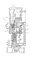
- a gas turbine 1 includes a compressor 3 that generates compressed air, a combustor 4 that generates fuel gas G by supplying fuel to the compressed air supplied from the compressor 3, and a combustor. 4 and a turbine 5 that is rotationally driven by the combustion gas G supplied from 4.
- the compressor 3 includes a compressor casing 3a that rotatably covers the rotor body 2, a plurality of compressor blades 3b that are fixed to the rotor body 2 and arranged in an annular shape, and an annular arrangement that is supported by the compressor casing 3a. And a plurality of compressor stationary blades 3c.
- the compressor rotor blades 3b and the compressor stationary blades 3c are alternately arranged in a plurality of stages in the direction of the axis O of the rotor.
- the turbine 5 rotatably covers the rotor body 2 and includes a turbine casing 5a having a combustion gas flow path F therein, a plurality of turbine blades 10 fixed to the rotor body 2 and arranged in an annular shape, and a turbine casing. And a plurality of turbine stationary blades 5b arranged in an annular shape supported by 5a.
- the turbine blades 10 and the turbine stationary blades 5 b are alternately arranged in a plurality of stages in the direction of the axis O of the rotor body 2.
- the radial direction of the rotor body 2 is simply referred to as “radial direction”
- the circumferential direction of the rotor body 2 is simply referred to as “circumferential direction”
- the axis O direction of the rotor body 2 is simply referred to as “axis line O”. It is called “direction”.
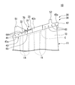
- the turbine rotor blade 10 includes a blade body 11 disposed in the combustion gas flow path F in FIG. 1, and a tip shroud 20 fixed to the radially outer side of the blade body 11. .
- a platform provided so as to protrude from the wing body 11 and a blade root projecting further radially inward from the platform are provided. Yes.
- the turbine rotor blade 10 is integrally fixed to the rotor body 2.
- the blade main body 11 is provided so as to extend from the rotor main body 2 toward the radially outer side of the rotor main body 2. Further, as shown in FIG. 3, the blade body 11 has a circumferential one side (rotational direction of the rotor body 2) from the leading edge on the upstream side of the combustion gas flow path to the trailing edge on the downstream side along the axis O direction. It has a blade-shaped cross section in which a pressure surface 12 and a suction surface 13 are formed so as to be convex toward the front side, the lower side of FIGS. 3 and 4. This cross-sectional shape is the other side in the circumferential direction (the rear side in the rotational direction of the rotor body 2, the upper side in FIGS.
- a plurality of (six in this embodiment) cooling passages 14 extending in the radial direction are formed inside the blade body 11.
- the cooling passages 14 are formed at intervals from each other, for example, so as to be arranged along the direction along the center line, that is, along the extending direction of the cross-sectional shape of the blade body 11.
- Cooling air (cooling medium) supplied from the radially inner side of the blade body 11 circulates in the cooling path 14 toward the radially outer side.
- the tip shroud 20 includes a shroud body 30 provided integrally with the wing body 11 and a plug 70 that is detachably attached to the shroud body 30.
- the shroud body 30 is formed in a plate shape having a predetermined thickness in the radial direction, and protrudes in the circumferential direction on the radially outer side of the wing body 11 with respect to the wing body 11. Are fixed together.
- a surface of the shroud main body 30 facing outward in the radial direction is an outer peripheral end surface 31 of the shroud main body 30.
- an upstream end surface 41 is a surface that faces one side in the axis O direction (the upstream side of the gas flow path, the left side in FIGS. 2 to 4) that extends upstream and extends in the circumferential direction.
- a surface that faces the other side in the axis O direction, which is the downstream side, and extends along the circumferential direction is a downstream end surface 42.
- the upstream end face 41 and the downstream end face 42 are parallel to each other.
- the surface of the tip shroud 20 facing the one side in the circumferential direction is a first contact surface 43
- the surface facing the other side in the circumferential direction is a second contact surface 44.
- the first contact surface 43 is composed of three surfaces, a first inclined surface 43a, a second inclined surface 43b, and a third inclined surface 43c.
- the first inclined surface 43a is connected to one side in the circumferential direction of the upstream end surface 41, and extends so as to incline toward the other side in the circumferential direction toward the other side in the axis O direction.
- the second inclined surface 43b is connected to the other side of the first inclined surface 43a in the axis O direction, and extends so as to incline toward the one side in the circumferential direction toward the other side in the axis O direction. .
- the third diameter inclined surface is connected to the other side of the second inclined surface 43b in the axis O direction, and extends so as to incline toward the one side in the circumferential direction toward the other side in the axis O direction.
- the side end face 42 is connected to one circumferential side.
- the second contact surface 44 includes three surfaces, a fourth inclined surface 44a, a fifth inclined surface 44b, and a sixth inclined surface 44c.
- the fourth inclined surface 44a is connected to the other circumferential side of the upstream end surface 41 and extends parallel to the first inclined surface 43a.
- the fifth inclined surface 44b is connected to the other side of the fourth inclined surface 44a in the axis O direction and extends in parallel with the second inclined surface 43b.
- the sixth inclined surface 44c is connected to the other side in the axis O direction of the fifth inclined surface 44b, extends in parallel with the third inclined surface 43c, and is connected to the other circumferential side of the downstream end surface 42. ing.
- connection location of the 1st inclined surface 43a and the 2nd inclined surface 43b is located in the axis line O direction one side rather than the connection location of the 4th inclined surface 44a and the 5th inclined surface 44b.
- connection location of the 2nd inclined surface 43b and the 3rd inclined surface 43c is located in the axis line O direction one side rather than the connection location of the 5th inclined surface 44b and the 6th inclined surface 44c.
- the second inclined surface 43 b in the first contact surface 43 of the shroud body 30 is the fifth inclined surface in the second contact surface 44 of the adjacent chip shroud 20. 44b slidably contacts.
- an annular ring is constituted by the plurality of chip shrouds 20.
- the shroud body 30 has a Z-shaped outer peripheral end surface 31 viewed from the radially outer side. ing.
- a first chip fin 51, a second chip fin 52, and a recess 60 are provided on the outer peripheral end surface 31 of the shroud body 30.
- the first chip fin 51 is provided at a location close to one side of the outer peripheral end surface 31 in the axis O direction, protrudes radially outward from the outer peripheral end surface 31, and the upstream end surface 41 over the entire circumferential direction of the outer peripheral end surface 31. It extends in parallel. Both ends of the first chip fin 51 in the circumferential direction are connected to the first inclined surface 43a and the fourth inclined surface 44a, respectively.
- the second chip fin 52 is provided at a location close to the other side in the axis O direction on the outer peripheral end surface 31, and protrudes radially outward from the outer peripheral end surface 31 in the same manner as the first chip fin 51. 31 extends in parallel with the downstream end face 42 over the entire circumferential direction. Note that. Both ends in the circumferential direction of the second chip fin 52 are connected to the third inclined surface 43c and the sixth inclined surface 44c, respectively. In this way, the first chip fin 51 and the second chip fin 52 are spaced apart from each other in the axis O direction and provided in parallel. The first tip fin 51 and the second tip fin 52 ensure the sealing performance between the turbine rotor blade 10 and the turbine casing.
- the recess 60 is formed between the first chip fin 51 and the second chip fin 52 on the outer peripheral end surface 31 so as to be recessed radially inward from the outer peripheral end surface 31 and is opened radially outward.
- the recess 60 extends in the direction along the outer peripheral end surface 31 as a longitudinal direction, and in the present embodiment, the direction toward the other side in the circumferential direction extends as the longitudinal direction as it goes toward the other side in the axis O direction. . That is, the recessed portion 60 extends in the longitudinal direction in the direction inclined to the circumferential direction of the rotor body 2 main body and the axis O direction, similarly to the extending direction of the cross-sectional shape of the blade body 11. Edges at both ends in the longitudinal direction of the recess 60 are each formed in an arc shape, and edges on both sides in the short direction of the recess 60 are formed in a straight line extending in the longitudinal direction in parallel with each other.
- the bottom surface 62 of the recess 60 has a part of the cooling passages 14 of the plurality of cooling passages 14 (in the present embodiment, among the six cooling passages 14). (3) of the outer ends in the radial direction are open. Thereby, the recessed part 60 and the one part cooling path 14 are made into the communication state. That is, the radially outer ends of the plurality of cooling passages 14 are arranged in directions that are inclined in the circumferential direction and the axis O direction of the rotor body 2 corresponding to the extending direction of the cross-sectional shape of the blade body 11. Yes.
- the end portions of the cooling passages 14 are opened in the recess portions 60 by forming the recess portions 60 with the arrangement direction of the end portions of the cooling passages 14 as the longitudinal direction.
- a plurality of cooling holes 63 are formed in the shroud body 30 so as to communicate the inside of the recess 60 and the third inclined surface 43 c of the first contact surface 43.
- a plurality of cooling holes 63 (not shown) that communicate with the fourth inclined surface 44a of the second contact surface 44 are formed.
- a plurality of cooling holes 64 are formed to communicate the inside of the recess 60 and the first inclined surface 43 a of the first contact surface 43.
- the openings in the third inclined surface 43c, the fourth inclined surface 44a and the first inclined surface 43a of the cooling holes 63 and 64 are in the extending direction of the third inclined surface 43c, the fourth inclined surface 44a and the first inclined surface 43a. Are arranged along. *
- the region of the outer peripheral end surface 31 that is located on the other side of the first tip fin 51 in the axis O direction and that is connected to the first inclined surface 43a and the fourth inclined surface 44a is the first main surface of the outer peripheral end surface 31. 32. Further, a portion of the outer peripheral end surface 31 on the front side in the longitudinal direction of the concave portion 60 (one end side in the longitudinal direction, that is, one side in the axial line O direction and one side in the circumferential direction) The insertion surface 36 is raised.
- region including the edge part except the longitudinal direction front side of the recessed part 60 in the outer peripheral end surface 31 surrounds this recessed part 60 from a transversal direction both sides and a longitudinal direction back side (Axis O direction other side and circumferential direction other side).
- the second main surface 33 protrudes radially outward from the first main surface 32 and the insertion surface 36. Accordingly, the recess 60 is formed so as to be recessed radially inward from the second main surface 33 of the outer peripheral end surface 31. Further, the front side of the recess 60 in the longitudinal direction is open to the insertion surface 36 side.
- Part of the plurality of cooling paths 14 (two of the six cooling paths 14 in the present embodiment) is opened in the first main surface 32 of the outer peripheral end surface 31.
- a portion of the second main surface 33 of the outer peripheral end surface 31 on the back side in the longitudinal direction of the recess 60 is a part of the plurality of cooling paths 14 (one of the six cooling paths 14 in the present embodiment). ) Is open.
- a pair of side surfaces 61 along the longitudinal direction of the recess 60 that is, a pair of side surfaces 61 opposed to the lateral direction of the recess 60, the mounting grooves 61 a extending along the longitudinal direction.
- the attachment groove 61 a is a groove that is recessed from the pair of side surfaces 61 so as to recede to a rectangle, and extends over the entire length of the recess 60.
- the radial position of the mounting groove 61a is substantially the same as the radial position of the insertion surface 36.
- the opening on the insertion surface 36 side of the recess 60 described above serves as a plug insertion port 65 for inserting a plug 70 described later into the mounting groove 61a.
- the distance between the plug insertion port 65 and the first chip fin 51 in the direction of the axis O is secured so that a first plug piece 71 and a second plug piece 72 described later can be inserted into the plug insertion port 65. Has been.
- the plug 70 is composed of a plurality of plug pieces.
- the plug 70 is composed of two plug pieces, ie, two first plug pieces 71 and second plug pieces 72.
- the first plug piece 71 is a plate-like member having substantially the same thickness as the radial groove width of the attachment groove 61a, and is inserted into the attachment groove 61a so that the first plug piece 71 in the longitudinal direction at the opening of the recess 60 The area can be closed.
- An end surface of the first plug piece 71 facing the front side in the longitudinal direction is a first abutting end surface 71a that is inclined toward one side in the lateral direction of the recess 60 toward the far side in the longitudinal direction. Note that the end surface of the first plug piece 71 facing the long side in the longitudinal direction is formed in an arc shape corresponding to the shape of the opening of the recess 60.
- the second plug piece 72 is a plate-like member having a thickness substantially the same as the groove width in the radial direction of the mounting groove 61a. The area on the side can be closed.
- the end surface of the second plug piece 72 facing the back side in the longitudinal direction is a second abutting end surface 72a that inclines toward the one side in the short direction of the recess 60 toward the back side in the longitudinal direction.
- a cavity C which is an isolated space, is defined.
- the first plug piece 71 is first inserted through the plug insertion port 65 from the distal end side, that is, the end surface side formed in an arc shape. Insert into the mounting groove 61a. As a result, both sides of the first plug piece 71 are sandwiched between the mounting grooves 61a, and movement of the first plug piece 71 in the radial direction is restricted. In this state, the first plug piece 71 is slid to the back side in the longitudinal direction of the recess 60 to dispose the first plug piece 71 in the region on the back side in the longitudinal direction of the opening of the recess 60. The tip of 71 is brought into contact with the back side in the longitudinal direction of the recess 60.
- the second plug piece 72 is inserted into the mounting groove 61a through the plug insertion port 65 from the tip end side thereof, that is, the second contact end face 72a side.
- both sides of the second plug piece 72 are sandwiched between the mounting grooves 61a, and the radial movement of the first plug piece 71 is restricted.
- the second plug piece 72 is slid to the rear side in the longitudinal direction of the concave portion 60, thereby placing the first plug piece 71 in the region on the front side in the longitudinal direction of the opening of the concave portion 60 and The end surface 72 a is brought into contact with the first contact end surface 71 a of the first plug piece 71.
- the first plug piece 71 and the second plug piece 72 are sequentially inserted into the mounting groove 61a, whereby the opening of the recess 60 is closed over the entire region, and the cavity C is formed.
- cooling air is supplied from the radially inner side to the cooling passage 14 in the blade body 11 during operation. Thereby, the wing body 11 is cooled from the inside.
- the cooling air that has reached the radially outer end of each cooling passage 14 merges in the cavity C in the chip shroud 20, and then is discharged to the outside of the chip shroud 20 through the cooling hole 63.
- the inner surface of the cooling hole 63 is cooled by the cooling air, whereby the chip shroud 20 is cooled from the inside.
- the plug 70 is composed of a first plug piece 71 and a second plug piece 72, and each of the first plug piece 71 and the second plug piece 72 is inserted into the mounting groove 61a. Since the opening of the recess 60 is closed, the deformation of the plug 70 can be reduced as compared with the case where the plug 70 is configured as a single piece. Therefore, the durability of the plug 70 can be improved, and the operation of the gas turbine can be continued for a long time.
- the plug 70 is divided in this way, even if the first chip fin 51 and the second chip fin 52 are provided on the side of the plug insertion port 65 in the axis O direction, the first plug piece 71 can be easily obtained.
- the second plug piece 72 can be inserted into the mounting groove 61a.
- the mounting grooves 61 a are formed in the pair of side surfaces 61 along the longitudinal direction of the recess 60, the facing direction of the pair of side surfaces 61 is the short direction of the recess 60. Therefore, the distance between the pair of mounting grooves 61a is set narrower than when the mounting grooves 61a are formed on the side surface of the recess 60 along the short direction. Thereby, since the space
- the plug 70 can be disposed so that the plug 70 is close to the mounting groove 61a over the entire longitudinal direction, the central portion of the plug 70 is deformed radially outward by centrifugal force. It can be reduced as much as possible. As a result, the swelling of the first plug piece 71 and the second plug piece 72 due to centrifugal force can be further reduced.
- the longitudinal direction of the recess 60 extends in a direction inclined from the axis O direction
- the chip fin is provided on the axis O direction side of the plug insertion port 65 of the recess 60. Even if it exists, the 1st plug piece 71 and the 2nd plug piece 72 can be easily inserted in the attachment groove
- a plug insertion port 65 is formed on the front side in the longitudinal direction of the recess 60 having the mounting groove 61a on the side surface 61.
- the plug insertion port 65 has a radial position substantially the same as that of the mounting groove 61a. Since the insertion surface 36 is formed, the first plug piece 71 and the second plug piece 72 can be easily guided to the mounting groove 61a. Thereby, the first plug piece 71 and the second plug piece 72 can be inserted into the mounting groove 61a easily and reliably.
- the outer peripheral end surface 31 of the shroud main body 30 has the first main surface 32 and the second main surface 33.
- a recess 60 may be formed on the surface.
- the region between the first chip fin 51 and the second chip fin 52 on the outer peripheral end surface 31 is formed into a smoothly curved outer peripheral surface, and is recessed from the outer peripheral end surface 31 radially outward.
- a recess 60 is formed on the surface.
- the opening of the recess 60 is closed by the plug 70 constituted by the first plug piece 71 and the second plug piece 72 inserted into the attachment groove 61a.
- the plug 70 is divided into the first plug piece 71 and the second plug piece 72 as in the embodiment, so that the swelling of the plug 70 due to centrifugal force can be reduced, and the plug 70 can be easily formed in the mounting groove 61a. Can be inserted.
- the plug 70 is composed of the first plug piece 71 and the second plug piece 72.
- the plug 70 is composed of three plug pieces 70a, 70b, 70c. May be.
- the size of each plug piece 70a, 70b, 70c is further smaller than that in the case where the plug 70 is divided into two, it is possible to further reduce the swelling due to the centrifugal force and to more easily insert it into the mounting groove 61a.
- the plug 70 may be divided into four or more.
- the mounting groove 61a is formed in a straight line shape, but the mounting groove 61a may be formed in a curved shape as shown in the second modification.
- a plug insertion opening 65 that opens toward the other side in the circumferential direction on the center side in the longitudinal direction of one of the pair of side surfaces 61 along the longitudinal direction of the recess 60.
- the first plug piece 71 and the second plug piece 72 may be inserted into the mounting groove 61a from the plug insertion port 65.
- the plug pieces 70a and 70c inserted from the plug insertion port 65 are moved one by one along the attachment groove 61a to the front side and the back side in the longitudinal direction.
- one plug piece 70c is further inserted into the plug insertion port 65, so that the opening of the recess 60 is closed by a total of three plug pieces 70a, 70b, 70c. Thereby, the swelling of the plug 70 due to the centrifugal force can be further reduced, and the plug 70 can be more easily inserted into the mounting groove.
- the cooling has been described as being performed using air, but is not limited to air, and may be, for example, steam. That is, a plurality of cooling passages 14 are provided in the turbine rotor blade 10, and steam flows in a part of the plurality of cooling passages 14 from the blade root toward the radially outer side of the rotor body 2, and this is provided in the tip shroud 20. In the cavity C formed by the recessed portion 60 and the plug 70, it is recovered. Next, the recovered steam flows through the remainder of the plurality of cooling paths 14 toward the radially inner side of the rotor body 2 and is recovered on the blade root side. According to this configuration, the durability of the plug 70 can be improved in the turbine rotor blade 10 using a cooling medium that requires recovery such as steam.
- the present invention provides a turbine rotor blade comprising: a blade body attached to the rotor body so as to extend radially outward of the rotor body from the rotor body; and a tip shroud fixed to the radially outer side of the blade body.
- a cooling path extending in the radial direction of the rotor main body and through which a cooling medium flows is formed in the blade body, and the tip shroud has an outer circumferential end surface that is open outward in the radial direction and communicates with the cooling path.
- a plug having a plurality of plug pieces that cooperate with each other to close the opening of the concave portion by being inserted into mounting grooves formed on the side surfaces of the concave portion, respectively. Concerning moving blades. According to the present invention, since the plug is divided into the plug pieces, the swelling based on the centrifugal force can be reduced, and the durability of the plug can be improved.
Landscapes
- Engineering & Computer Science (AREA)
- Mechanical Engineering (AREA)
- General Engineering & Computer Science (AREA)
- Turbine Rotor Nozzle Sealing (AREA)
Abstract
本発明に係るタービン動翼(10)は、ロータ本体(2)から該ロータ本体(2)の径方向外側に延びるように該ロータ本体(2)に取り付けられる翼本体(11)と、該翼本体(11)の前記径方向外側に固定されたチップシュラウド(20)と、を備えるタービン動翼(10)において、前記翼本体(11)内に、前記ロータ本体(2)の径方向に延び、冷却媒体が流通する冷却路(14)が形成され、前記チップシュラウド(20)は、前記径方向外側に開口し、且つ前記冷却路(14)に連通する凹部(60)が外周端面に形成されたシュラウド本体(30)と、前記凹部(60)の側面に形成された取付溝(61a)にそれぞれ挿入されることで、互いに協働して前記凹部(60)の開口を閉塞する複数のプラグ片(71,72)を有するプラグ(70)と、を備える。
Description
本発明は、タービン動翼及びこれを備えたガスタービンに関する。
本願は、2011年10月27日に日本に出願された特願2011-236148号について優先権を主張し、その内容をここに援用する。
本願は、2011年10月27日に日本に出願された特願2011-236148号について優先権を主張し、その内容をここに援用する。
近年、ガスタービンの高温、高効率化が進み、これに伴ってタービン動翼の翼高さも増大化(長大翼化)傾向にある。特に、後方段動翼では、排出される燃焼ガスの熱エネルギーを抑える必要があり、翼高さの増大化が著しくなっている。このような動翼では、翼高さの増大化に伴って振動数が低下することで、フラッターなどの不安定な振動モードが発生する可能性が高まる。
そこで、各タービン動翼を構成する翼本体の先端にチップシュラウドが配され、構造減衰を増加させることで不安定な振動モードの発生を抑えている。このチップシュラウドもガスタービンの高温化にともない冷却する必要があるため、該チップシュラウド内には冷却構造が形成されている。
このような冷却構造としては、例えば特許文献1に示すように、翼本体を冷却した冷却空気をチップシュラウドの冷却にも使用できるように、翼本体内の冷却路と連通するキャビティをチップシュラウド内に形成したものが知られている。このキャビティは、チップシュラウドに冷却路と連通する凹部を形成し、当該凹部の開口をプラグで閉塞することで形成される。これにより、冷却空気をキャビティに導入し、該キャビティを介して冷却媒体をチップシュラウドの外周に供給することで該チップシュラウドの冷却を図っている。
また、特許文献2には、ロータの回転による遠心力で上記プラグが外れてしまうことを防ぐために、凹部の一対の側面にそれぞれ取付溝を形成し、該取付溝にプラグを挿入することで凹部の開口を閉塞してキャビティを構成する技術が記載されている。より具体的には、この特許文献2の取付溝はロータの軸方向に対向するように形成されており、該取付溝に一枚のプラグが周方向から挿入されることで開口が閉塞されるようになっている。
しかしながら、上記特許文献2の技術では、プラグにおける取付溝に挿入されていない部分が遠心力によってロータの径方向外側に膨らんでしまうという問題がある。即ち、一対の取付溝がロータの軸方向に対向してこれら取付溝同士の間隔がある程度離間しているため、プラグに作用する遠心力やキャビティ内外の圧力差によってプラグの中央部が径方向外側にクリープ変形し易くなってしまう。したがって、このクリープ変形に基くプラグ自体の膨らみにより、長期間にわたって使用した場合にはプラグの耐久性が低減するおそれがある。
本発明はこのような課題に鑑みてなされたものであって、プラグの耐久性を向上させることが可能なタービン動翼及びこれを備えたガスタービンを提供することを目的とする。
(1)本発明に係るタービン動翼は、ロータ本体から該ロータ本体の径方向外側に延びるように該ロータ本体に取り付けられる翼本体と、該翼本体の前記径方向外側に固定されたチップシュラウドと、を備えるタービン動翼において、前記翼本体内に、前記ロータ本体の径方向に延び、冷却媒体が流通する冷却路が形成され、前記チップシュラウドは、前記径方向外側に開口し、且つ前記冷却路に連通する凹部が外周端面に形成されたシュラウド本体と、前記凹部の側面に形成された取付溝にそれぞれ挿入されることで、互いに協働して前記凹部の開口を閉塞する複数のプラグ片を有するプラグと、を備える。
このような特徴のタービン動翼によれば、プラグを複数のプラグ片で形成し、各プラグ片のそれぞれを取付溝に挿入したため、プラグを一枚物として構成した場合に比べて膨らみを低減させることができる。
(2)前記凹部は、前記外周端面に沿う方向を長手方向として延在し、前記取付溝は、前記長手方向に沿う一対の前記側面に形成され、複数の前記プラグ片は、互いに当接するように前記長手方向に並んで前記凹部の開口を閉塞することが好ましい。
この場合には、凹部の長手方向に沿う一対の側面に取付溝が形成されていることから、一対の側面の対向方向は凹部の短手方向となる。したがって、凹部の短手方向に沿う側面に取付溝を形成した場合に比べて、一対の取付溝の間隔が狭く設定される。これにより、取付溝に挿入されるプラグ片における該取付溝の対向方向の間隔も狭く設定することができるため、遠心力によるプラグ片の変形を低減させることができ、該プラグ片の膨らみをより一層低減させることが可能となる。
(3)前記冷却路は、前記翼本体の内部に複数形成され、複数の前記冷却路の径方向外側の端部は、前記ロータ本体の周方向及び軸線方向にそれぞれ傾斜する方向に配列され、前記凹部は、複数の前記冷却路の径方向外側の端部の配列方向を前記長手方向として延在していることが好ましい。
この場合には、凹部の長手方向が周方向及び軸線方向に傾斜する方向に延在することになるため、例えばチップシュラウドの外周端面に、プラグ片を挿入する際の障害物がある場合であっても、該プラグ片を容易に取付溝に挿入することができる。また、ロータの回転加速度によってプラグ片が外れてしまうことを防止できる。
(4)前記シュラウド本体は、前記凹部の長手方向の少なくとも一端側に、前記プラグ片を前記取付溝に挿入するためのプラグ挿入口を有することが好ましい。
この場合には、容易かつ確実に取付溝にプラグ片を挿入することができる。
(5)前記シュラウド本体は、前記外周端面から突出し、且つ前記ロータ本体の周方向に延びるとともに前記ロータ本体の軸線方向に間隔をあけて配置された、複数のチップフィンを有し、前記凹部は、前記複数のチップフィンの間に形成されていることが好ましい。
この場合には、複数のチップフィンがシュラウド本体の外周端面に形成されている際であっても、プラグが複数のプラグ片からなることにより、チップフィンが障害となり難く、これらプラグ片を容易に取付溝に挿入することができる。
また、上述したように凹部が周方向及び軸線方向に傾斜して形成した場合には、チップフィンが存在する場合であってもより容易にプラグ片を取付溝に挿入することができる。
また、上述したように凹部が周方向及び軸線方向に傾斜して形成した場合には、チップフィンが存在する場合であってもより容易にプラグ片を取付溝に挿入することができる。
(6)本発明に係るガスタービンは、上記いずれかのタービン動翼が取り付けられた前記ロータ本体と、該ロータ本体を回転可能に覆うケーシングとを備えていることを特徴とする。
このような特徴のガスタービンでは、上述したタービン動翼を備えているため、プラグの膨らみを低減させることができる。
このような特徴のガスタービンでは、上述したタービン動翼を備えているため、プラグの膨らみを低減させることができる。
本発明に係るタービン動翼及びガスタービンによれば、プラグを各プラグ片に分割したことにより遠心力に基く膨らみを低減させることができ、プラグの耐久性を向上させることが可能になる。
以下、本発明に係る実施形態について図面を参照して説明する。
図1に示すように、ガスタービン1は、圧縮空気を生成する圧縮機3と、圧縮機3から供給される圧縮空気に燃料を供給して燃焼ガスGを生成する燃焼器4と、燃焼器4から供給される燃焼ガスGにより回転駆動されるタービン5とを備えている。
図1に示すように、ガスタービン1は、圧縮空気を生成する圧縮機3と、圧縮機3から供給される圧縮空気に燃料を供給して燃焼ガスGを生成する燃焼器4と、燃焼器4から供給される燃焼ガスGにより回転駆動されるタービン5とを備えている。
圧縮機3は、ロータ本体2を回転可能に覆う圧縮機ケーシング3aと、ロータ本体2に固定されて環状に配列された複数の圧縮機動翼3bと、圧縮機ケーシング3aに支持されて環状に配列された複数の圧縮機静翼3cとを備えている。圧縮機動翼3b及び圧縮機静翼3cは、ロータの軸線O方向に複数段交互に配されている。
また、タービン5は、ロータ本体2を回転可能に覆い、内部を燃焼ガス流路Fとするタービンケーシング5aと、ロータ本体2に固定され環状に配列された複数のタービン動翼10と、タービンケーシング5aに支持されて環状に配列された複数のタービン静翼5bとを備えている。タービン動翼10及びタービン静翼5bは、ロータ本体2の軸線O方向に複数段交互に配されている。
なお、以下では、ロータ本体2の径方向を単に「径方向」と称するとともにロータ本体2の周方向を単に「周方向」と称し、さらに、該ロータ本体2の軸線O方向を単に「軸線O方向」と称する。
なお、以下では、ロータ本体2の径方向を単に「径方向」と称するとともにロータ本体2の周方向を単に「周方向」と称し、さらに、該ロータ本体2の軸線O方向を単に「軸線O方向」と称する。
次に、タービン動翼10の詳細について図を参照して説明する。
図2に示すように、タービン動翼10は、図1における燃焼ガス流路F内に配される翼本体11と、翼本体11の径方向外側に固定されたチップシュラウド20とを備えている。なお、図示は省略するが、翼本体11の径方向内側には、該翼本体11から張り出すように設けられたプラットフォームと、プラットフォームからさらに径方向内側に突出する翼根と、が設けられている。この翼根がロータ本体2の外周面に取り付けられることで、タービン動翼10がロータ本体2に一体に固定される。
図2に示すように、タービン動翼10は、図1における燃焼ガス流路F内に配される翼本体11と、翼本体11の径方向外側に固定されたチップシュラウド20とを備えている。なお、図示は省略するが、翼本体11の径方向内側には、該翼本体11から張り出すように設けられたプラットフォームと、プラットフォームからさらに径方向内側に突出する翼根と、が設けられている。この翼根がロータ本体2の外周面に取り付けられることで、タービン動翼10がロータ本体2に一体に固定される。
翼本体11は、図2に示すように、ロータ本体2から該ロータ本体2の径方向外側に向かって延びるように設けられている。また、この翼本体11は、図3に示すように、軸線O方向に沿って燃焼ガス流路上流側となる前縁から下流側となる後縁にかけて周方向一方側(ロータ本体2の回転方向前方側、図3及び図4の下側)へ凸となるように湾曲して正圧面12及び負圧面13が形成された翼形状の断面を有している。この断面形状は、軸線O方向他方側(ガス流路の下流側、図2~図4の右側)に向かうに従って周方向他方側(ロータ本体2の回転方向後方側、図3及び4の上側)に向かうように延在する翼形状とされている。
また、翼本体11の延在方向に直交する断面における正圧面12と負圧面13とから等しい距離にある点を前縁から後縁まで結んだ曲線が中心線とされており、この中心線は翼本体11の湾曲形状と同様に湾曲している。
また、翼本体11の延在方向に直交する断面における正圧面12と負圧面13とから等しい距離にある点を前縁から後縁まで結んだ曲線が中心線とされており、この中心線は翼本体11の湾曲形状と同様に湾曲している。
さらに、翼本体11の内部には、図2に示すように、径方向に延びる複数(本実施形態では6つ)の冷却路14が形成されている。この冷却路14は、例えば上記中心線に沿う方向に沿って配列されるように、即ち、翼本体11の上記断面形状の延在方向に沿って配列されるように、互いに間隔をあけて形成されている。
翼本体11の径方向内側から供給される冷却空気(冷却媒体)は、当該冷却路14内を径方向外側に向かって流通する。
翼本体11の径方向内側から供給される冷却空気(冷却媒体)は、当該冷却路14内を径方向外側に向かって流通する。
チップシュラウド20は、翼本体11に一体に設けられたシュラウド本体30と、該シュラウド本体30に着脱可能に取り付けられるプラグ70とを備えている。
シュラウド本体30は、図2から図4に示すように、径方向に所定の厚みを有する板状に形成され、翼本体11の径方向外側において周方向に張り出すように該翼本体11に対して一体に固定されている。このシュラウド本体30における径方向外側を向く面は、該シュラウド本体30の外周端面31とされている。
このシュラウド本体30においては、上流側である軸線O方向一方側(ガス流路の上流側、図2~図4の左側)を向き、且つ周方向に沿って延びる面が上流側端面41とされ、下流側である軸線O方向他方側を向き、且つ周方向に沿って延びる面が下流側端面42とされている。これら上流側端面41と下流側端面42とは互いに平行とされている。
また、図3及び図4に示すように、チップシュラウド20における周方向一方側を向く面が第一コンタクト面43とされ、周方向他方側を向く面が第二コンタクト面44とされている。
また、図3及び図4に示すように、チップシュラウド20における周方向一方側を向く面が第一コンタクト面43とされ、周方向他方側を向く面が第二コンタクト面44とされている。
第一コンタクト面43は、第一傾斜面43aと第二傾斜面43bと第三傾斜面43cとの3つの面から構成されている。
第一傾斜面43aは、上流側端面41の周方向一方側に接続されており、軸線O方向他方側に向かうに従って周方向他方側に向かって傾斜するように延在している。また、第二傾斜面43bは、第一傾斜面43aの軸線O方向他方側に接続されており、軸線O方向他方側に向かうに従って周方向一方側に向かって傾斜するように延在している。そして、第三径傾斜面は、第二傾斜面43bの軸線O方向他方側に接続されており、軸線O方向他方側に向かうに従って周方向一方側に向かって傾斜するように延在し、下流側端面42の周方向一方側に接続されている。
第一傾斜面43aは、上流側端面41の周方向一方側に接続されており、軸線O方向他方側に向かうに従って周方向他方側に向かって傾斜するように延在している。また、第二傾斜面43bは、第一傾斜面43aの軸線O方向他方側に接続されており、軸線O方向他方側に向かうに従って周方向一方側に向かって傾斜するように延在している。そして、第三径傾斜面は、第二傾斜面43bの軸線O方向他方側に接続されており、軸線O方向他方側に向かうに従って周方向一方側に向かって傾斜するように延在し、下流側端面42の周方向一方側に接続されている。
第二コンタクト面44は、第四傾斜面44aと第五傾斜面44bと第六傾斜面44cとの3つの面から構成されている。
第四傾斜面44aは、上流側端面41における周方向他方側に接続されており第一傾斜面43aと平行に延びている。また、第五傾斜面44bは、第四傾斜面44aの軸線O方向他方側に接続されており、第二傾斜面43bと平行に延在している。そして、第六傾斜面44cは、第五傾斜面44bの軸線O方向他方側に接続されており、第三傾斜面43cと平行に延在し、下流側端面42の周方向他方側に接続されている。
第四傾斜面44aは、上流側端面41における周方向他方側に接続されており第一傾斜面43aと平行に延びている。また、第五傾斜面44bは、第四傾斜面44aの軸線O方向他方側に接続されており、第二傾斜面43bと平行に延在している。そして、第六傾斜面44cは、第五傾斜面44bの軸線O方向他方側に接続されており、第三傾斜面43cと平行に延在し、下流側端面42の周方向他方側に接続されている。
なお、第一傾斜面43aと第二傾斜面43bとの接続箇所は、第四傾斜面44aと第五傾斜面44bとの接続箇所よりも軸線O方向一方側に位置している。また、第二傾斜面43bと第三傾斜面43cとの接続箇所は、第五傾斜面44bと第六傾斜面44cとの接続箇所よりも軸線O方向一方側に位置している。
各タービン動翼10がロータ本体2に取り付けられた際には、シュラウド本体30の第一コンタクト面43における第二傾斜面43bは、隣り合うチップシュラウド20の第二コンタクト面44における第五傾斜面44bに摺動可能に当接する。これにより、複数のチップシュラウド20により円環状のリングが構成される。
以上のような、上流側端面41、下流側端面42、第一コンタクト面43及び第二コンタクト面44によって、シュラウド本体30は、径方向外側から見た外周端面31の形状がZ字状とされている。
このシュラウド本体30の外周端面31には、図2~図4に示すように、第一チップフィン51、第二チップフィン52及び凹部60が設けられている。
第一チップフィン51は、外周端面31における軸線O方向一方側に近接した箇所に設けられており、該外周端面31から径方向外側に突出し、外周端面31の周方向全域にわたって上流側端面41と平行に延びている。なお、第一チップフィン51の周方向の両端は、それぞれ第一傾斜面43a及び第四傾斜面44aに接続されている。
また、第二チップフィン52は、外周端面31における軸線O方向他方側に近接した箇所に設けられており、第一チップフィン51と同様に、該外周端面31から径方向外側に突出し、外周端面31の周方向全域にわたって下流側端面42と平行に延びている。なお。第二チップフィン52の周方向の両端は、それぞれ第三傾斜面43c及び第六傾斜面44cに接続されている。
このようにして、第一チップフィン51及び第二チップフィン52は、互いに軸線O方向に離間して平行に設けられている。これら第一チップフィン51及び第二チップフィン52によって、タービン動翼10とタービンケーシングとの間のシール性が確保される。
凹部60は、外周端面31における上記第一チップフィン51と第二チップフィン52との間において、該外周端面31から径方向内側に凹むように形成され、径方向外側に開口している。この凹部60は、外周端面31に沿う方向を長手方向として延在しており、本実施形態では、軸線O方向他方側に向かうに従って周方向他方側に向かう方向を長手方向として延在している。即ち、この凹部60は、翼本体11の上記断面形状の延在方向と同様、ロータ本体2本体の周方向及び軸線O方向にそれぞれ傾斜する方向を長手方向として延在している。この凹部60の長手方向の両端の縁部はそれぞれ円弧状に形成され、該凹部60の短手方向の両側の縁部は互いに平行に長手方向に延びる直線状に形成されている。
そして、図2、図4及び図5に示すように、凹部60の底面62には、上記複数の冷却路14のうちの一部の冷却路14(本実施形態では6つの冷却路14のうちの3つ)の径方向外側の端部が開口している。これによって、凹部60とこれら一部の冷却路14とは連通状態とされている。
即ち、複数の冷却路14の径方向外側の端部は、翼本体11の上記断面形状の延在方向に対応してロータ本体2の周方向及び軸線O方向にそれぞれ傾斜する方向に配列されている。そして、これら冷却路14の端部の配列方向を長手方向として凹部60が延在するように形成されていることにより、凹部60内に一部の冷却路14の端部が開口している。
即ち、複数の冷却路14の径方向外側の端部は、翼本体11の上記断面形状の延在方向に対応してロータ本体2の周方向及び軸線O方向にそれぞれ傾斜する方向に配列されている。そして、これら冷却路14の端部の配列方向を長手方向として凹部60が延在するように形成されていることにより、凹部60内に一部の冷却路14の端部が開口している。
また、シュラウド本体30内には、該凹部60内と第一コンタクト面43の第三傾斜面43cとを連通する複数の冷却孔63(図2参照)が形成されているとともに、該凹部60内と第二コンタクト面44の第四傾斜面44aとを連通する複数の冷却孔63(図示省略)が形成されている。さらに、シュラウド本体30内には、凹部60内と第一コンタクト面43の第一傾斜面43aとを連通する複数の冷却孔64が形成されている。これら冷却孔63、64の第三傾斜面43c、第四傾斜面44a及び第一傾斜面43aにおける開口は、第三傾斜面43c、第四傾斜面44a及び第一傾斜面43aの延在方向に沿って配列されている。
ここで、外周端面31における第一チップフィン51よりも軸線O方向他方側に位置し、第一傾斜面43a及び第四傾斜面44aに接続される領域は、該外周端面31の第一主面32とされている。
また、外周端面31における凹部60の長手方向手前側(長手方向一端側、即ち、軸線O方向一方側かつ周方向一方側)の箇所は、第一主面32よりも一段径方向外側に平坦状に隆起した挿入面36とされている。
また、外周端面31における凹部60の長手方向手前側(長手方向一端側、即ち、軸線O方向一方側かつ周方向一方側)の箇所は、第一主面32よりも一段径方向外側に平坦状に隆起した挿入面36とされている。
そして、外周端面31における凹部60の長手方向手前側を除く縁部を含む領域は、該凹部60を短手方向両側及び長手方向奥側(軸線O方向他方側かつ周方向他方側)から囲うように第一主面32及び挿入面36よりも径方向外側に隆起した第二主面33とされている。したがって、凹部60は、外周端面31の第二主面33から径方向内側に凹むように形成されている。また、凹部60の長手方向手前側は、挿入面36側に開口している。
外周端面31の第一主面32には、複数の冷却路14のうちの一部(本実施形態においては6つの冷却路14のうちの2つ)が開口している。また、外周端面31の第二主面33における凹部60の長手方向奥側の箇所には、複数の冷却路14のうちの一部(本実施形態においては6つの冷却路14のうちの1つ)が開口している。
そして、図5に示すように、凹部60におけるその長手方向に沿う一対の側面61、即ち、該凹部60短手方向に対向する一対の側面61には、該長手方向に沿って延びる取付溝61aが形成されている。この取付溝61aは、一対の側面61からそれぞれ矩形に後退するように凹む溝であって、凹部60の長手方向全域にわたって延びている。
この取付溝61aの径方向位置は、挿入面36の径方向位置と略同一とされている。上述した凹部60の挿入面36側への開口は、後述するプラグ70を当該取付溝61aに挿入するためのプラグ挿入口65とされている。なお、プラグ挿入口65と第一チップフィン51との軸線O方向の間隔は、後述する第一プラグ片71及び第二プラグ片72がプラグ挿入口65に挿入可能となる分だけの寸法が確保されている。
プラグ70は、図3及び図6に示すように、複数のプラグ片から構成されており、本実施形態では2つの第一プラグ片71及び第二プラグ片72の二つのプラグ片から構成されている。
第一プラグ片71は、取付溝61aの径方向の溝幅と略同一の厚みを有する板状の部材であって、取付溝61aに挿入されることで、凹部60の開口における長手方向奥側の領域を閉塞可能とされている。
この第一プラグ片71における上記長手方向手前側を向く端面は、該長手方向奥側に向かうに従って凹部60の短手方向一方側に向かって傾斜する第一当接端面71aとされている。
なお、第一プラグ片71の上記長手方向奥側を向く端面は、凹部60の開口の形状に対応して円弧状に形成されている。
第一プラグ片71は、取付溝61aの径方向の溝幅と略同一の厚みを有する板状の部材であって、取付溝61aに挿入されることで、凹部60の開口における長手方向奥側の領域を閉塞可能とされている。
この第一プラグ片71における上記長手方向手前側を向く端面は、該長手方向奥側に向かうに従って凹部60の短手方向一方側に向かって傾斜する第一当接端面71aとされている。
なお、第一プラグ片71の上記長手方向奥側を向く端面は、凹部60の開口の形状に対応して円弧状に形成されている。
また、第二プラグ片72は、第一プラグ片71と同様に、取付溝61aの径方向の溝幅と略同一の厚みを有する板状の部材であって、凹部60の開口における長手方向手前側の領域を閉塞可能とされている。
この第二プラグ片72における上記長手方向奥側を向く端面は、該長手方向奥側に向かうに従って凹部60の短手方向一方側に向かって傾斜する第二当接端面72aとされている。
この第二プラグ片72における上記長手方向奥側を向く端面は、該長手方向奥側に向かうに従って凹部60の短手方向一方側に向かって傾斜する第二当接端面72aとされている。
これら第一プラグ片71、第二プラグ片72は、取付溝61aに挿入された際に、並ぶようにして第一当接端面71a及び第二当接端面72aが互いに当接することにより、協働して凹部60の開口を閉塞する。このように、第一プラグ片71及び第二プラグ片72からなるプラグ70によって凹部60の開口が閉塞されることによって、図5に示すように、チップシュラウド20内には該チップシュラウド20外部と隔離された空間であるキャビティCが画成される。
プラグ70によって凹部60の開口を閉塞する際には、図6Aに示すように、まず第一プラグ片71をその先端側、即ち、円弧状に形成された端面側からプラグ挿入口65を介して取付溝61aに挿入する。これによって、第一プラグ片71の両側が取付溝61aにそれぞれ挟み込まれた状態となり、第一プラグ片71の径方向の移動が規制される。そして、この状態で第一プラグ片71を凹部60の長手方向奥側にスライドさせることで、凹部60の開口の長手方向奥側の領域に第一プラグ片71を配置させて、第一プラグ片71の先端を凹部60の長手方向奥側に当接させる。
続いて、図6Bに示すように、第二プラグ片72をその先端側、即ち、第二当接端面72a側からプラグ挿入口65を介して取付溝61aに挿入する。これによって、第二プラグ片72の両側が取付溝61aにそれぞれ挟み込まれた状態となり、第一プラグ片71の径方向の移動が規制される。そして、この状態で第二プラグ片72を凹部60の長手方向奥側にスライドさせることで、凹部60の開口の長手方向手前側の領域に第一プラグ片71を配置させて、第二当接端面72aを第一プラグ片71の第一当接端面71aに当接させる。
このように第一プラグ片71及び第二プラグ片72が取付溝61aに順次挿入されることで、凹部60の開口がその全域にわたって閉塞され、上記キャビティCが形成される。
このように第一プラグ片71及び第二プラグ片72が取付溝61aに順次挿入されることで、凹部60の開口がその全域にわたって閉塞され、上記キャビティCが形成される。
以上のような構成のガスタービン動翼10を備えたガスタービン1においては、運転時に冷却空気が該翼本体11内の冷却路14に径方向内側から供給される。これによって、翼本体11が内部から冷却される。
また、各冷却路14の径方向外側の端部に到達した冷却空気は、チップシュラウド20内のキャビティCにて合流した後、冷却孔63を通ってチップシュラウド20の外部に放出される。このとき、冷却孔63の内面が冷却空気によって冷却されることで、チップシュラウド20がその内部から冷却される。
また、各冷却路14の径方向外側の端部に到達した冷却空気は、チップシュラウド20内のキャビティCにて合流した後、冷却孔63を通ってチップシュラウド20の外部に放出される。このとき、冷却孔63の内面が冷却空気によって冷却されることで、チップシュラウド20がその内部から冷却される。
ここで、ガスタービンの運転時には、ロータ本体2の回転に伴い遠心力が発生し、当該遠心力がチップシュラウド20のプラグ70にも作用する。これに対して本実施形態では、プラグ70を第一プラグ片71及び第二プラグ片72から構成し、これら第一プラグ片71及び第二プラグ片72のそれぞれを取付溝61aに挿入することにより凹部60の開口を閉塞したため、プラグ70を一枚物として構成した場合に比べて該プラグ70の変形を低減させることができる。したがって、プラグ70の耐久性を向上させることができ、長時間にわたってガスタービンの運転を継続させることができる。
また、このようにプラグ70が分割されているため、プラグ挿入口65の軸線O方向側に第一チップフィン51及び第二チップフィン52がある場合であっても、容易に第一プラグ片71、第二プラグ片72を取付溝61aに挿入することができる。
さらに、本実施形態では、凹部60の長手方向に沿う一対の側面61に取付溝61aが形成されていることから、一対の側面61の対向方向は凹部60の短手方向となる。したがって、凹部60の短手方向に沿う側面に取付溝61aを形成した場合に比べて、一対の取付溝61aの間隔が狭く設定される。これにより、第一プラグ片71及び第二プラグ片72における取付溝61aの対向方向の間隔も狭く設定することができるため、遠心力による第一プラグ片71及び第二プラグ片72の変形を低減させることができる。
即ち、プラグ70がその長手方向全域にわたって取付溝61aに対して近接するように該プラグ70を配置することができるため、プラグ70の中央部が遠心力によって径方向外側に変形してしまうことを極力低減させることができる。
これによって、遠心力による第一プラグ片71及び第二プラグ片72の膨らみをより一層低減させることが可能となる。
即ち、プラグ70がその長手方向全域にわたって取付溝61aに対して近接するように該プラグ70を配置することができるため、プラグ70の中央部が遠心力によって径方向外側に変形してしまうことを極力低減させることができる。
これによって、遠心力による第一プラグ片71及び第二プラグ片72の膨らみをより一層低減させることが可能となる。
また、本実施形態では、凹部60の長手方向が軸線O方向から傾斜する方向に延在しているため、凹部60のプラグ挿入口65の軸線O方向側にチップフィンが設けられている場合であっても、当該チップフィンが妨げになることなく第一プラグ片71及び第二プラグ片72を容易に取付溝61aに挿入することができる。
さらに、凹部60の長手方向が周方向から傾斜する方向に延在しているため、ロータ本体2の周方向の回転加速度によって第一プラグ片71及び第二プラグ片72が取付溝61aから外れて凹部60が露出してしまうことを防止できる。
さらに、凹部60の長手方向が周方向から傾斜する方向に延在しているため、ロータ本体2の周方向の回転加速度によって第一プラグ片71及び第二プラグ片72が取付溝61aから外れて凹部60が露出してしまうことを防止できる。
また、本実施形態では、側面61に取付溝61aを有する凹部60の長手方向手前側にプラグ挿入口65が形成されており、該プラグ挿入口65に取付溝61aと略同一の径方向位置の挿入面36が形成されているため、第一プラグ片71及び第二プラグ片72を容易に取付溝61aへと案内することができる。これによって、容易かつ確実に取付溝61aに第一プラグ片71及び第二プラグ片72を挿入することができる。
以上、本発明の実施形態について詳細に説明したが、本発明の技術的思想を逸脱しない限り、これらに限定されることはなく、多少の設計変更等も可能である。
例えば実施形態では、シュラウド本体30における外周端面31が第一主面32、第二主面33を有するものとしたが、例えば図7の模式図に示す変形例のように、滑らかな外周端面31に凹部60が形成されたものであってもよい。
即ち、この変形例では、外周端面31における第一チップフィン51と第二チップフィン52との間の領域が、滑らかに湾曲する外周面状とされ、当該外周端面31から径方向外側に凹むように凹部60が形成されている。そして、実施形態と同様に、取付溝61aに挿入される第一プラグ片71及び第二プラグ片72から構成されたプラグ70によって凹部60の開口が閉塞されるようになっている。これによっても、実施形態同様、プラグ70を第一プラグ片71及び第二プラグ片72に分割したことにより、遠心力によるプラグ70の膨らみを低減できる他、該プラグ70を容易に取付溝61aに挿入することができる。
また、実施形態では、プラグ70を第一プラグ片71及び第二プラグ片72から構成したが、図8に示す第二変形例として、プラグ70を3つのプラグ片70a,70b,70cから構成してもよい。この場合、各プラグ片70a,70b,70cの大きさがプラグ70を二分割した場合よりもさらに小さくなるため、遠心力による膨らみをより低減できるとともにより取付溝61aに挿入し易くなる。なお、プラグ70を4つ以上に分割してもよい。また、実施形態では取付溝61aは直線状に形成されていたが、第二変形例に示すように取付溝61aが曲線状に形成されていてもよい。
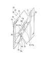
さらに、例えば第三変形例として、図9に示すように、凹部60の長手方向に沿う一対の側面61のうちの一方における長手方向中央側に周方向他方側に向けて開口するプラグ挿入口65を設け、当該プラグ挿入口65から第一プラグ片71及び第二プラグ片72を取付溝61a内に挿入するようにしてもよい。この第三変形例では、プラグ挿入口65から挿入されたプラグ片70a,70cは、取付溝61aに沿って長手方向手前側、奥側に一枚ずつ移動される。その後、プラグ挿入口65にさらに一枚のプラグ片70cを挿入することで、計3枚のプラグ片70a,70b,70cによって凹部60の開口を閉塞することとしている。これによって、遠心力によるプラグ70の膨らみをより低減できるとともによりプラグ70を取付溝に挿入し易くすることができる。
また、実施形態では冷却について空気を使って行われるものとして説明したが、空気に限られるものではなく、例えば蒸気であってもよい。即ち、タービン動翼10に複数の冷却路14を設け、複数の冷却路14の一部には蒸気を翼根からロータ本体2の径方向外側に向けて流し、これをチップシュラウド20に設けられた凹部60とプラグ70とにより形成されたキャビティCに回収する。次に、回収された蒸気を、複数の冷却路14の残りを通じてロータ本体2の径方向内側に向けて流し、翼根側で回収する。この構成によれば、蒸気のような回収を要する冷却媒体を用いるタービン動翼10において、プラグ70の耐久性を向上することができる。
本発明は、ロータ本体から該ロータ本体の径方向外側に延びるように該ロータ本体に取り付けられる翼本体と、該翼本体の前記径方向外側に固定されたチップシュラウドと、を備えるタービン動翼において、前記翼本体内に、前記ロータ本体の径方向に延び、冷却媒体が流通する冷却路が形成され、前記チップシュラウドは、前記径方向外側に開口すると共に前記冷却路に連通する凹部が外周端面に形成されたシュラウド本体と、前記凹部の側面に形成された取付溝にそれぞれ挿入されることで、互いに協働して前記凹部の開口を閉塞する複数のプラグ片を有するプラグと、を備えるタービン動翼に関する。本発明によれば、プラグを各プラグ片に分割したことにより遠心力に基く膨らみを低減させることができ、プラグの耐久性を向上させることが可能になる。
1 ガスタービン
2 ロータ本体
5 タービン
5a タービンケーシング
10 タービン動翼
11 翼本体
14 冷却路
20 チップシュラウド
30 シュラウド本体
31 外周端面
51 第一チップフィン(チップフィン)
52 第二チップフィン(チップフィン)
60 凹部
61 側面
61a 取付溝
62 底面
65 プラグ挿入口
70 プラグ
70a プラグ片
70b プラグ片
70c プラグ片
71 第一プラグ片(プラグ片)
71a 第一当接端面
72 第二プラグ片(第二プラグ片)
72a 第二当接端面
C キャビティ
2 ロータ本体
5 タービン
5a タービンケーシング
10 タービン動翼
11 翼本体
14 冷却路
20 チップシュラウド
30 シュラウド本体
31 外周端面
51 第一チップフィン(チップフィン)
52 第二チップフィン(チップフィン)
60 凹部
61 側面
61a 取付溝
62 底面
65 プラグ挿入口
70 プラグ
70a プラグ片
70b プラグ片
70c プラグ片
71 第一プラグ片(プラグ片)
71a 第一当接端面
72 第二プラグ片(第二プラグ片)
72a 第二当接端面
C キャビティ
Claims (6)
- ロータ本体から該ロータ本体の径方向外側に延びるように該ロータ本体に取り付けられる翼本体と、該翼本体の前記径方向外側に固定されたチップシュラウドと、を備えるタービン動翼において、
前記翼本体内に、前記ロータ本体の径方向に延び、冷却媒体が流通する冷却路が形成され、
前記チップシュラウドは、
前記径方向外側に開口し、且つ前記冷却路に連通する凹部が外周端面に形成されたシュラウド本体と、
前記凹部の側面に形成された取付溝にそれぞれ挿入されることで、互いに協働して前記凹部の開口を閉塞する複数のプラグ片を有するプラグと、を備えるタービン動翼。 - 前記凹部は、前記外周端面に沿う方向を長手方向として延在し、
前記取付溝は、前記長手方向に沿う一対の前記側面に形成され、
複数の前記プラグ片は、互いに当接するように前記長手方向に並んで前記凹部の開口を閉塞する、請求項1に記載のタービン動翼。 - 前記冷却路は、前記翼本体の内部に複数形成され、
複数の前記冷却路の径方向外側の端部は、前記ロータ本体の周方向及び軸線方向にそれぞれ傾斜する方向に配列され、
前記凹部は、複数の前記冷却路の径方向外側の端部の配列方向を前記長手方向として延在している、請求項2に記載のタービン動翼。 - 前記シュラウド本体は、
前記凹部の長手方向の少なくとも一端側に、前記プラグ片を前記取付溝に挿入するためのプラグ挿入口を有する、請求項1から3のいずれか一項に記載のタービン動翼。 - 前記シュラウド本体は、
前記外周端面から突出し、且つ前記ロータ本体の周方向に延びるとともに前記ロータ本体の軸線方向に間隔をあけて配置された、複数のチップフィンを有し、
前記凹部は、前記複数のチップフィンの間に形成されている、請求項1から4のいずれか一項に記載のタービン動翼。 - 請求項1から5のいずれか一項に記載のタービン動翼が取り付けられた前記ロータ本体と、
該ロータ本体を回転可能に覆うケーシングと、
を備えるガスタービン。
Priority Applications (3)
| Application Number | Priority Date | Filing Date | Title |
|---|---|---|---|
| EP12844208.4A EP2752555B1 (en) | 2011-10-27 | 2012-10-24 | Turbine blade, and gas turbine including same |
| KR1020147000124A KR101551132B1 (ko) | 2011-10-27 | 2012-10-24 | 터빈 동익 및 이것을 구비한 가스 터빈 |
| CN201280036830.9A CN103703216B (zh) | 2011-10-27 | 2012-10-24 | 涡轮动叶片及具备该涡轮动叶片的燃气轮机 |
Applications Claiming Priority (2)
| Application Number | Priority Date | Filing Date | Title |
|---|---|---|---|
| JP2011-236148 | 2011-10-27 | ||
| JP2011236148A JP5881369B2 (ja) | 2011-10-27 | 2011-10-27 | タービン動翼及びこれを備えたガスタービン |
Publications (1)
| Publication Number | Publication Date |
|---|---|
| WO2013061997A1 true WO2013061997A1 (ja) | 2013-05-02 |
Family
ID=48167824
Family Applications (1)
| Application Number | Title | Priority Date | Filing Date |
|---|---|---|---|
| PCT/JP2012/077455 WO2013061997A1 (ja) | 2011-10-27 | 2012-10-24 | タービン動翼及びこれを備えたガスタービン |
Country Status (6)
| Country | Link |
|---|---|
| US (1) | US9371741B2 (ja) |
| EP (1) | EP2752555B1 (ja) |
| JP (1) | JP5881369B2 (ja) |
| KR (1) | KR101551132B1 (ja) |
| CN (1) | CN103703216B (ja) |
| WO (1) | WO2013061997A1 (ja) |
Families Citing this family (9)
| Publication number | Priority date | Publication date | Assignee | Title |
|---|---|---|---|---|
| US10202852B2 (en) * | 2015-11-16 | 2019-02-12 | General Electric Company | Rotor blade with tip shroud cooling passages and method of making same |
| US11092039B2 (en) * | 2016-10-27 | 2021-08-17 | General Electric Company | Apparatus for circumferential separation of turbine blades |
| US10494932B2 (en) * | 2017-02-07 | 2019-12-03 | General Electric Company | Turbomachine rotor blade cooling passage |
| US11060407B2 (en) * | 2017-06-22 | 2021-07-13 | General Electric Company | Turbomachine rotor blade |
| JP6842563B2 (ja) * | 2017-10-11 | 2021-03-17 | 三菱重工エンジン&ターボチャージャ株式会社 | 遠心式回転機械のインペラ及び遠心式回転機械 |
| JP7064076B2 (ja) * | 2018-03-27 | 2022-05-10 | 三菱重工業株式会社 | タービン翼及びタービン並びにタービン翼の固有振動数のチューニング方法 |
| US11143286B2 (en) * | 2019-03-15 | 2021-10-12 | Hamilton Sundstrand Corporation | Differential unit gear shrouds |
| KR102120417B1 (ko) * | 2020-05-27 | 2020-06-08 | 두산중공업 주식회사 | 터빈블레이드, 터빈 및 이를 포함하는 가스터빈 |
| CN114211438B (zh) * | 2021-12-14 | 2023-08-18 | 东方电气集团东方汽轮机有限公司 | 一种横置式静叶片装配方法及定位工装 |
Citations (4)
| Publication number | Priority date | Publication date | Assignee | Title |
|---|---|---|---|---|
| JPH11223103A (ja) * | 1998-02-04 | 1999-08-17 | Mitsubishi Heavy Ind Ltd | ガスタービン動翼 |
| JP2000291405A (ja) * | 1999-04-05 | 2000-10-17 | General Electric Co <Ge> | ガスタービン・バケット及び上部シュラウド用冷却回路 |
| JP2000297604A (ja) | 1999-04-01 | 2000-10-24 | General Electric Co <Ge> | ガスタービンバケット及びチップシュラウド用の冷却回路 |
| JP2010031865A (ja) | 2008-07-29 | 2010-02-12 | General Electric Co <Ge> | ロータブレード及びそれを製作する方法 |
Family Cites Families (10)
| Publication number | Priority date | Publication date | Assignee | Title |
|---|---|---|---|---|
| CH580750A5 (ja) * | 1974-07-17 | 1976-10-15 | Bbc Sulzer Turbomaschinen | |
| CH582305A5 (ja) * | 1974-09-05 | 1976-11-30 | Bbc Sulzer Turbomaschinen | |
| US4073599A (en) * | 1976-08-26 | 1978-02-14 | Westinghouse Electric Corporation | Hollow turbine blade tip closure |
| JPH03194101A (ja) * | 1989-12-21 | 1991-08-23 | Toshiba Corp | ガスタービン冷却動翼 |
| JP3510467B2 (ja) | 1998-01-13 | 2004-03-29 | 三菱重工業株式会社 | ガスタービンの動翼 |
| US6019572A (en) * | 1998-08-06 | 2000-02-01 | Siemens Westinghouse Power Corporation | Gas turbine row #1 steam cooled vane |
| JP2003065068A (ja) | 2001-08-29 | 2003-03-05 | Mitsubishi Heavy Ind Ltd | ガスタービン翼頂部の加工孔閉塞方法 |
| US6942450B2 (en) * | 2003-08-22 | 2005-09-13 | Siemens Westinghouse Power Corporation | Differential pressure sensing system for airfoils usable in turbine engines |
| US7625172B2 (en) * | 2006-04-26 | 2009-12-01 | United Technologies Corporation | Vane platform cooling |
| US7946816B2 (en) * | 2008-01-10 | 2011-05-24 | General Electric Company | Turbine blade tip shroud |
-
2011
- 2011-10-27 JP JP2011236148A patent/JP5881369B2/ja active Active
-
2012
- 2012-10-24 KR KR1020147000124A patent/KR101551132B1/ko active IP Right Grant
- 2012-10-24 EP EP12844208.4A patent/EP2752555B1/en active Active
- 2012-10-24 WO PCT/JP2012/077455 patent/WO2013061997A1/ja active Application Filing
- 2012-10-24 CN CN201280036830.9A patent/CN103703216B/zh active Active
- 2012-10-25 US US13/660,431 patent/US9371741B2/en active Active
Patent Citations (4)
| Publication number | Priority date | Publication date | Assignee | Title |
|---|---|---|---|---|
| JPH11223103A (ja) * | 1998-02-04 | 1999-08-17 | Mitsubishi Heavy Ind Ltd | ガスタービン動翼 |
| JP2000297604A (ja) | 1999-04-01 | 2000-10-24 | General Electric Co <Ge> | ガスタービンバケット及びチップシュラウド用の冷却回路 |
| JP2000291405A (ja) * | 1999-04-05 | 2000-10-17 | General Electric Co <Ge> | ガスタービン・バケット及び上部シュラウド用冷却回路 |
| JP2010031865A (ja) | 2008-07-29 | 2010-02-12 | General Electric Co <Ge> | ロータブレード及びそれを製作する方法 |
Non-Patent Citations (1)
| Title |
|---|
| See also references of EP2752555A4 |
Also Published As
| Publication number | Publication date |
|---|---|
| CN103703216B (zh) | 2015-09-30 |
| EP2752555A1 (en) | 2014-07-09 |
| KR101551132B1 (ko) | 2015-09-07 |
| CN103703216A (zh) | 2014-04-02 |
| EP2752555B1 (en) | 2019-06-19 |
| JP2013092138A (ja) | 2013-05-16 |
| EP2752555A4 (en) | 2015-05-06 |
| US20130142667A1 (en) | 2013-06-06 |
| US9371741B2 (en) | 2016-06-21 |
| KR20140029513A (ko) | 2014-03-10 |
| JP5881369B2 (ja) | 2016-03-09 |
Similar Documents
| Publication | Publication Date | Title |
|---|---|---|
| JP5881369B2 (ja) | タービン動翼及びこれを備えたガスタービン | |
| EP3392462B1 (en) | Insert assembly, blade, gas turbine, and blade manufacturing method | |
| EP2990608B1 (en) | Rotor blade and gas turbine equipped with same | |
| JP6344869B2 (ja) | タービン静翼、タービン、及び、タービン静翼の改造方法 | |
| JP5017064B2 (ja) | トリフォリアル先端空洞翼形部 | |
| JP4762524B2 (ja) | ガスタービンエンジンロータ組立体を冷却するための方法及び装置 | |
| EP2758634B1 (en) | Impingement cooling of turbine blades or vanes | |
| JP4902157B2 (ja) | 先端に溝を備えたタービン動翼 | |
| JP5442190B2 (ja) | 相似形先端部バッフルエーロフォイル | |
| JP4572405B2 (ja) | ガスタービンロータブレードを冷却するための方法及び装置 | |
| EP2372090B1 (en) | Apparatus for cooling a bucket assembly | |
| JP2005337258A (ja) | ロータブレード | |
| JPWO2010109954A1 (ja) | タービン翼およびガスタービン | |
| EP2586967B1 (en) | Thermal plug for turbine bucket shank cavity and related method | |
| JP2017036710A (ja) | 静翼、及びこれを備えているガスタービン | |
| KR20220155187A (ko) | 돌기 어레이를 갖는 가스 터빈 내부 슈라우드 | |
| CN111058899B (zh) | 具有转子盘唇缘的转子组件 | |
| EP3489464B1 (en) | Seal structure for gas turbine rotor blade | |
| JP4363149B2 (ja) | タービン用シール構造、シールステータ、及びタービンノズルセグメント | |
| CN116988852A (zh) | 降低透平动叶带凹槽叶尖换热系数的机匣台阶造型结构 |
Legal Events
| Date | Code | Title | Description |
|---|---|---|---|
| 121 | Ep: the epo has been informed by wipo that ep was designated in this application |
Ref document number: 12844208 Country of ref document: EP Kind code of ref document: A1 |
|
| ENP | Entry into the national phase |
Ref document number: 20147000124 Country of ref document: KR Kind code of ref document: A |
|
| WWE | Wipo information: entry into national phase |
Ref document number: 2012844208 Country of ref document: EP |
|
| NENP | Non-entry into the national phase |
Ref country code: DE |