WO2013061808A1 - 車両駆動用誘導電動機の制御装置 - Google Patents
車両駆動用誘導電動機の制御装置 Download PDFInfo
- Publication number
- WO2013061808A1 WO2013061808A1 PCT/JP2012/076567 JP2012076567W WO2013061808A1 WO 2013061808 A1 WO2013061808 A1 WO 2013061808A1 JP 2012076567 W JP2012076567 W JP 2012076567W WO 2013061808 A1 WO2013061808 A1 WO 2013061808A1
- Authority
- WO
- WIPO (PCT)
- Prior art keywords
- current value
- torque
- axis current
- phase
- unit
- Prior art date
- Legal status (The legal status is an assumption and is not a legal conclusion. Google has not performed a legal analysis and makes no representation as to the accuracy of the status listed.)
- Ceased
Links
Images


Classifications
-
- B—PERFORMING OPERATIONS; TRANSPORTING
- B60—VEHICLES IN GENERAL
- B60L—PROPULSION OF ELECTRICALLY-PROPELLED VEHICLES; SUPPLYING ELECTRIC POWER FOR AUXILIARY EQUIPMENT OF ELECTRICALLY-PROPELLED VEHICLES; ELECTRODYNAMIC BRAKE SYSTEMS FOR VEHICLES IN GENERAL; MAGNETIC SUSPENSION OR LEVITATION FOR VEHICLES; MONITORING OPERATING VARIABLES OF ELECTRICALLY-PROPELLED VEHICLES; ELECTRIC SAFETY DEVICES FOR ELECTRICALLY-PROPELLED VEHICLES
- B60L15/00—Methods, circuits, or devices for controlling the traction-motor speed of electrically-propelled vehicles
- B60L15/02—Methods, circuits, or devices for controlling the traction-motor speed of electrically-propelled vehicles characterised by the form of the current used in the control circuit
- B60L15/025—Methods, circuits, or devices for controlling the traction-motor speed of electrically-propelled vehicles characterised by the form of the current used in the control circuit using field orientation; Vector control; Direct Torque Control [DTC]
-
- H—ELECTRICITY
- H02—GENERATION; CONVERSION OR DISTRIBUTION OF ELECTRIC POWER
- H02P—CONTROL OR REGULATION OF ELECTRIC MOTORS, ELECTRIC GENERATORS OR DYNAMO-ELECTRIC CONVERTERS; CONTROLLING TRANSFORMERS, REACTORS OR CHOKE COILS
- H02P21/00—Arrangements or methods for the control of electric machines by vector control, e.g. by control of field orientation
- H02P21/14—Estimation or adaptation of machine parameters, e.g. flux, current or voltage
- H02P21/20—Estimation of torque
-
- B—PERFORMING OPERATIONS; TRANSPORTING
- B60—VEHICLES IN GENERAL
- B60L—PROPULSION OF ELECTRICALLY-PROPELLED VEHICLES; SUPPLYING ELECTRIC POWER FOR AUXILIARY EQUIPMENT OF ELECTRICALLY-PROPELLED VEHICLES; ELECTRODYNAMIC BRAKE SYSTEMS FOR VEHICLES IN GENERAL; MAGNETIC SUSPENSION OR LEVITATION FOR VEHICLES; MONITORING OPERATING VARIABLES OF ELECTRICALLY-PROPELLED VEHICLES; ELECTRIC SAFETY DEVICES FOR ELECTRICALLY-PROPELLED VEHICLES
- B60L2240/00—Control parameters of input or output; Target parameters
- B60L2240/40—Drive Train control parameters
- B60L2240/42—Drive Train control parameters related to electric machines
- B60L2240/423—Torque
-
- B—PERFORMING OPERATIONS; TRANSPORTING
- B60—VEHICLES IN GENERAL
- B60L—PROPULSION OF ELECTRICALLY-PROPELLED VEHICLES; SUPPLYING ELECTRIC POWER FOR AUXILIARY EQUIPMENT OF ELECTRICALLY-PROPELLED VEHICLES; ELECTRODYNAMIC BRAKE SYSTEMS FOR VEHICLES IN GENERAL; MAGNETIC SUSPENSION OR LEVITATION FOR VEHICLES; MONITORING OPERATING VARIABLES OF ELECTRICALLY-PROPELLED VEHICLES; ELECTRIC SAFETY DEVICES FOR ELECTRICALLY-PROPELLED VEHICLES
- B60L2240/00—Control parameters of input or output; Target parameters
- B60L2240/40—Drive Train control parameters
- B60L2240/42—Drive Train control parameters related to electric machines
- B60L2240/429—Current
-
- B—PERFORMING OPERATIONS; TRANSPORTING
- B60—VEHICLES IN GENERAL
- B60L—PROPULSION OF ELECTRICALLY-PROPELLED VEHICLES; SUPPLYING ELECTRIC POWER FOR AUXILIARY EQUIPMENT OF ELECTRICALLY-PROPELLED VEHICLES; ELECTRODYNAMIC BRAKE SYSTEMS FOR VEHICLES IN GENERAL; MAGNETIC SUSPENSION OR LEVITATION FOR VEHICLES; MONITORING OPERATING VARIABLES OF ELECTRICALLY-PROPELLED VEHICLES; ELECTRIC SAFETY DEVICES FOR ELECTRICALLY-PROPELLED VEHICLES
- B60L2240/00—Control parameters of input or output; Target parameters
- B60L2240/40—Drive Train control parameters
- B60L2240/52—Drive Train control parameters related to converters
- B60L2240/529—Current
-
- B—PERFORMING OPERATIONS; TRANSPORTING
- B60—VEHICLES IN GENERAL
- B60L—PROPULSION OF ELECTRICALLY-PROPELLED VEHICLES; SUPPLYING ELECTRIC POWER FOR AUXILIARY EQUIPMENT OF ELECTRICALLY-PROPELLED VEHICLES; ELECTRODYNAMIC BRAKE SYSTEMS FOR VEHICLES IN GENERAL; MAGNETIC SUSPENSION OR LEVITATION FOR VEHICLES; MONITORING OPERATING VARIABLES OF ELECTRICALLY-PROPELLED VEHICLES; ELECTRIC SAFETY DEVICES FOR ELECTRICALLY-PROPELLED VEHICLES
- B60L2260/00—Operating Modes
- B60L2260/40—Control modes
- B60L2260/44—Control modes by parameter estimation
-
- Y—GENERAL TAGGING OF NEW TECHNOLOGICAL DEVELOPMENTS; GENERAL TAGGING OF CROSS-SECTIONAL TECHNOLOGIES SPANNING OVER SEVERAL SECTIONS OF THE IPC; TECHNICAL SUBJECTS COVERED BY FORMER USPC CROSS-REFERENCE ART COLLECTIONS [XRACs] AND DIGESTS
- Y02—TECHNOLOGIES OR APPLICATIONS FOR MITIGATION OR ADAPTATION AGAINST CLIMATE CHANGE
- Y02T—CLIMATE CHANGE MITIGATION TECHNOLOGIES RELATED TO TRANSPORTATION
- Y02T10/00—Road transport of goods or passengers
- Y02T10/60—Other road transportation technologies with climate change mitigation effect
- Y02T10/64—Electric machine technologies in electromobility
Definitions
- the present invention relates to a control device for an induction motor for driving a vehicle.
- Hybrid motors and electric vehicles are equipped with a large number of electric motors, among which high output motors are used for driving.
- a speed detector that detects the rotational speed of the induction motor is provided, and control is performed based on the speed by the speed detector.
- a vector control method is adopted in which a three-phase alternating current is converted into a rotating coordinate system having two orthogonal axes (see, for example, Patent Document 1).
- the torque Tm of the induction motor in the vector control method is expressed by the following equation (1) at a target operating point where the motor constant has no error and the secondary magnetic flux coincides with the d axis.
- m is a conversion coefficient
- Pp is the number of pole pairs
- M is a mutual inductance
- l2 is a secondary leakage inductance
- ⁇ ′ is a secondary linkage flux
- Iq is a q-axis current.
- the torque Tm of the induction motor is estimated by Equation (1), and the primary frequency is corrected according to the difference between the estimated torque value and the torque command value. The error from the estimated torque value is corrected.
- the present invention is a control device that outputs a control signal to an inverter that drives a vehicle drive induction motor at a high frequency based on a torque command and a magnetic flux command input from a host controller, and the drive frequency that sets the drive frequency of the inverter
- a setting unit a current value detection unit that detects a three-phase current value of the induction motor, a conversion unit that converts the detected three-phase current value into a d-axis current value and a q-axis current value, and an output torque of the induction motor
- a torque estimation unit for estimating, based on a phase compensation amount for correcting a current phase change from current detection by the current value detection unit to torque estimation, and a d-axis current value and a q-axis current value. Then, the output torque is estimated.
- the accuracy of torque estimation can be improved.
- FIG. 1 is an overall block diagram of a vehicle equipped with a motor control device according to an embodiment of the present invention.
- 3 is a block diagram showing in detail a motor control calculation unit in a motor controller 109. It is a figure which shows the relationship between UVW phase stationary coordinate system, (alpha) (beta) axis
- the block diagram which shows the structure of the torque estimation part 211 in the case of changing the value of C0 and C1 by power running and regeneration.
- FIG. 1 is an overall block diagram of an electric vehicle equipped with a motor control device according to an embodiment of the present invention.
- the electric vehicle includes a power supply unit 101 and a motor drive unit 102.
- the power supply unit 101 includes a battery 103, a cell controller 104, a relay circuit 105, and a battery controller 106.
- the relay circuit 105 can connect and disconnect the inverter 107 and the battery 103.
- the cell controller 104 acquires battery information and monitors the state of the battery 103.
- the battery information acquired by the cell controller 104 is transmitted to the battery controller 106 by communication means (not shown).
- the battery controller 106 performs SOC calculation of the battery 103, calculation of a power limit value to the motor driving unit 102, and the like based on the received battery information, and controls power supply to and interruption of the motor driving unit 102.
- the motor drive unit 102 includes at least one inverter and one motor.
- the motor drive unit 102 is provided with an induction motor 108 for driving the vehicle, an inverter 107 for driving the induction motor 108, and a motor controller 109 for motor control.
- the motor controller 109 generates a drive signal to the inverter 107 based on the torque target value or the rotational speed target value received from the host controller 110 that controls the entire vehicle by communication means or the like, and generates the generated torque or rotational speed of the motor. Control.
- a converter or the like these devices may be included.
- FIG. 2 is a block diagram showing in detail a motor control calculation unit in the motor controller 109 of FIG.
- the motor control calculation unit 201 includes a DC voltage detection unit 204, a motor rotation number calculation unit 207, a motor current detection unit 209, a current command calculation unit 214, a slip frequency calculation unit 217, a primary frequency calculation unit 219, a coordinate conversion unit 223, a current An FB control calculation unit 225, a voltage FF control calculation unit 227, a coordinate conversion unit 231, and a PWM duty calculation unit 233 are provided.
- the motor control calculation unit 201 controls the induction motor 108 by vector control, and the relationship of each coordinate system used in vector control is shown in FIG.
- FIG. 3 shows the relationship between the output current and the UVW phase stationary coordinate system, the ⁇ axis stationary coordinate system and the dq axis rotational coordinate system.
- the phase angle from the stationary coordinate system ⁇ -axis to the rotating coordinate system d-axis is ⁇ dq
- the phase angle from the rotating coordinate system d-axis to the current vector I1 is ⁇ .
- the dq-axis rotating coordinate system rotates at a primary frequency ⁇ 1, which will be described later, with respect to the ⁇ stationary coordinate system.
- the three-phase current detection value is expressed as a primary current vector I1 having Id and Iq as components when coordinate transformation is performed based on vector control theory.
- the target operating point for vector control is a state where the secondary magnetic flux vector coincides with the d-axis.
- the current command calculation unit 214 controls the d (magnetic flux) axis current command Idref and q (torque) axis current command Iqref which are control current commands.
- Is calculated. Idref is expressed by equation (2)
- Iqref is expressed by equation (3).
- M is a mutual inductance
- L2 is a secondary side self-inductance
- p is the number of pole pairs.
- the optimum value of the secondary magnetic flux command ⁇ 2ref changes according to the battery voltage. Therefore, the correction value of the secondary magnetic flux command ⁇ 2ref corresponding to the DC voltage 203 output from the DC voltage detector 204 is calculated, and Idref and Iqref are calculated based on the correction values.
- the motor current detection unit 209 detects the U-phase current Iu and the W-phase current Iw of the induction motor 108 based on the motor drive current data acquired by the current sensor 208.
- the coordinate conversion unit 223 separately generates the d-axis (excitation) current Id and the q-axis (torque) current Iq based on the phase angle ⁇ dq (current phase) from the ⁇ axis to the d axis. A method for calculating the phase angle ⁇ dq will be described later.
- Id is expressed by equation (4)
- Iq is expressed by equation (5).
- the current FB control calculation unit 225 corrects the d-axis voltage command VdRef so that the d-axis current command IdRef and the d-axis current Id match. Similarly, the current FB control calculation unit 225 corrects the q-axis voltage command VqRef so that the q-axis current command IqRef and the q-axis current Iq match. These voltage command values are output as the FB voltage command 226. Further, the voltage FF control calculation unit 227 performs feedforward control that compensates for the voltage drop and induced voltage of the primary resistance, and outputs the FF voltage command 228.
- the voltage command applied to the motor is the sum of the FB voltage command and the FF voltage command, and is expressed as Equation (6) and Equation (7).
- L1 is the primary self-inductance
- ⁇ L1 is the primary leakage inductance
- Kp is the proportional gain
- Ki is the integral gain.
- VdRef and VqRef are converted into three-phase voltage commands VuRef, VvRef and VwRef by the coordinate conversion unit 231 and output as the voltage command 230.
- Vuref is expressed by equation (8)
- Vvref is expressed by equation (9)
- Vwref is expressed by equation (10).
- the PWM duty calculator 233 generates a gate command 234 for the switching element in the inverter 107 based on the three-phase voltage commands VuRef, VvRef, and VwRef, and outputs it to the inverter 107. Since this PWM control is a well-known technique, its detailed description is omitted here.
- the induction motor 108 is provided with a motor rotation sensor 205.
- the motor rotation number calculation unit 207 calculates the motor rotation number ⁇ r based on the data acquired by the motor rotation sensor 205.
- the slip frequency calculation unit 217 calculates the slip frequency reference ⁇ s * based on the d-axis (excitation) current command IdRef and the q-axis (torque) current command IqRef. ⁇ s * is expressed by equation (11).
- R2 is a secondary resistance
- L2 is a secondary self-inductance.
- the primary frequency calculation unit 219 calculates ⁇ 1 which is the output frequency of the inverter 107 and is the motor primary frequency. ⁇ 1 is expressed by the following equation (12). That is, the output frequency of the inverter 107 is set to ⁇ 1 calculated by the equation (12). Then, by integrating the primary frequency ⁇ 1 by the integration calculation unit 220, the phase angle ⁇ dq (current phase) from the stationary coordinate system ⁇ -axis to the d-axis of the rotating coordinate system shown in FIG. 3 is calculated.
- the torque Tm of the induction motor 108 is expressed by the equation (1) at the target operating point where the motor constant has no error and the secondary flux linkage coincides with the d-axis.
- m is a conversion coefficient
- Pp is the number of pole pairs
- M is a mutual inductance
- l2 is a secondary leakage inductance
- ⁇ ' is a secondary linkage flux
- Iq is a q-axis current.
- Id ⁇ Iq is calculated by taking the three-phase current value detected by the current detector 208 into the motor controller 108 and converting the three-phase current value based on the phase information (phase angle ⁇ dq).
- FIG. 4 is a diagram showing a relationship when the current phase changes by ⁇ during the time lag from the current detection to the calculation of Id ⁇ Iq (that is, the calculation of the estimated torque value).
- the three-phase current detection value is expressed as a primary current vector I1 having Id and Iq as components when coordinate transformation is performed based on the vector control theory.
- the primary current vector I1 has a phase angle ⁇ with respect to the rotating coordinate system d-axis, and the relationships shown in the following equations (15) and (16) are established between I1 and Id and Iq.
- phase shift ⁇ can be expressed as the following equation (22).
- the coefficients C0 and C1 included in the equation (22) are constants specific to the motor drive system, and are determined by actual measurement, for example, and stored in advance in the torque estimation unit 211 of FIG.
- the torque estimation unit 211 calculates a phase shift ⁇ from the primary frequency ⁇ 1 calculated by the primary frequency calculation unit 219 and the equation (22), and based on the calculated ⁇ and Id and Iq from the coordinate conversion unit 223.
- the corrected torque estimated value Tm shown in equation (21) is calculated.
- the calculated estimated torque value Tm is output to the host controller 110.
- the phase shift ⁇ is calculated based on predetermined C0 and C1 regardless of the driving state of the induction motor 108 (power running drive, regenerative drive), but whether the induction motor 108 is power running drive or regenerative drive.
- the values of C0 and C1 may differ depending on whether or not. Therefore, as shown in FIG. 7, a torque command Tmref is input to the torque estimation unit 211, and torque estimation according to power running and regeneration is performed.
- the switching control unit 304 connects the switching unit 303 to the storage unit 301 when the input torque command Tmref is positive (powering driving), and switches the switching unit 303 when the torque command Tmref is negative (regenerative driving).
- ⁇ may be calculated using the same C0 and C1 regardless of whether it is power running drive or regenerative drive.
- the current phase shift ⁇ may be a constant instead of changing according to the primary frequency ⁇ 1.
- an average value of the primary frequency ⁇ 1 is adopted as a constant.
- the input of ⁇ 1 to the torque estimation unit 211 as shown in FIG. 1 is not necessary.
- FIG. 5 and 6 are comparisons between the actual measured motor torque value and the estimated torque value calculated by the motor control calculation unit 201.
- FIG. FIG. 5 shows a case of a conventional torque estimated value (torque estimated value calculated by Expression (14)), and FIG. 6 shows a case of the torque estimated value of the present embodiment.
- the motor rotation speed ⁇ r is kept constant, and the motor torque command value is increased in a ramp shape.
- the output frequency of the inverter 107 (the primary frequency ⁇ 1), which is the drive frequency, is set by the primary frequency calculation unit 219.
- the torque estimator 211 includes a phase compensation amount (for example, a phase shift ⁇ calculated by the equation (22)) for correcting a current phase change from current detection by the motor current detector 209 to torque estimation, a d-axis current value, and q Based on the shaft current value, the output torque Tm of the induction motor 108 is estimated. As a result, the influence of the time lag from the current detection to the torque estimation value calculation on the torque estimation is reduced, and the torque estimation accuracy can be improved.
- the host controller 110 inputs an appropriate torque command Tmref and secondary magnetic flux command ⁇ 2ref to the motor controller 109 based on the estimated torque value calculated by the motor controller 109. Therefore, by improving the accuracy of the estimated torque value input from the motor controller 109, an appropriate torque command Tmref and secondary magnetic flux command ⁇ 2ref corresponding to the driving status of the induction motor 108 can be given to the motor controller 109.
- phase compensation amount may be a constant as described above.
- the switching control unit 304 determines power running and regeneration of the induction motor 108 based on the input torque command Tmref.
- the calculation unit 305 of the torque estimation unit 211 calculates the power running phase compensation amount ⁇ using the values C01 and C11 of the storage unit 301, and sets the power running phase compensation amount ⁇ to the power running phase compensation amount ⁇ . Based on this, an estimated torque value is calculated.
- the calculation unit 305 of the torque estimation unit 211 calculates the regeneration phase compensation amount ⁇ using the values C02 and C12 of the storage unit 301, and the regeneration phase compensation amount. An estimated torque value is calculated based on ⁇ .
- phase compensation amount is a constant
- the values of C0 and C1 are changed between power running and regeneration.
- a constant value for power running and a constant value for regeneration are obtained.
- 101 power supply unit
- 102 motor drive unit
- 107 inverter
- 108 induction motor
- 109 motor controller
- 110 host controller
- 209 motor current detection unit
- 211 torque estimation unit
- 214 current command calculation unit
- 219 primary frequency calculation unit
- 223, 230 coordinate conversion unit
- 301, 302 storage unit
Landscapes
- Engineering & Computer Science (AREA)
- Power Engineering (AREA)
- Transportation (AREA)
- Mechanical Engineering (AREA)
- Control Of Ac Motors In General (AREA)
Abstract
トルク推定の精度を向上させることができる、車両駆動用誘導電動機の制御装置。 上位コントローラ110から入力されるトルク指令Tmrefおよび二次磁束指令φ2refに基づいて、車両駆動用誘導電動機108を高周波駆動するインバータ107に制御信号を出力するモータコントローラ109は、インバータ107の駆動周波数ω1を設定する一次周波数演算部219と、誘導電動機108の三相電流値を検出するモータ電流値検出部209と、検出された三相電流値をd軸電流値Idおよびq軸電流値Iqに変換する座標変換部223と、誘導電動機108の出力トルクを推定するトルク推定部211と、を備え、トルク推定部211は、モータ電流値検出部209による電流検出からトルク推定までの電流位相変化を補正する位相補償量と、d軸電流値およびq軸電流値とに基づいて、出力トルクTmを推定する。
Description
本発明は、車両駆動用誘導電動機の制御装置に関する。
ハイブリッド自動車や電気自動車などには多数の電動機が搭載されており、中でも駆動用に高出力電動機が用いられている。誘導電動機の制御装置では、誘導電動機の回転速度を検出する速度検出器が備えられ、当該速度検出器により速度に基づいて制御が行われている。一般に、誘導電動機の制御においては、三相交流電流を直交する2軸を持つ回転座標系に変換して取り扱うベクトル制御方式が採用されている(例えば、特許文献1参照)。
ベクトル制御方式における誘導電動機のトルクTmは、電動機定数に誤差が無く、二次磁束がd軸に一致した目標動作点において、次式(1)により表される。式(1)において、mは変換係数、Ppは極対数、Mは相互インダクタンス、l2は2次側漏れインダクタンス、φ'は二次鎖交磁束、Iqはq軸電流を示す。

特許文献1に記載の発明では、式(1)により誘導電動機のトルクTmを推定し、このトルク推定値とトルク指令値との差分に応じて一次周波数の補正を行うことで、トルク指令値とトルク推定値との誤差を修正するようにしている。
上述のようにベクトル制御理論に基づきトルク推定を行う場合、検出した三相電流よりd軸電流Idおよびq軸電流Iqを算出する必要がある。しかし、電流センサにより検出された電流をモータコントローラが取得してから、三相-二相変換によってIdおよびIqを算出し、さらにトルク推定演算を行うまでにはタイムラグが生じる。
そのタイムラグの間にも電流の位相は変化するため、トルク推定演算に用いられる三相電流値と、トルク推定演算を行う瞬間に検出される三相電流との間には、電流の位相変化に起因するずれが生じている。そのため、このずれの発生によりトルク推定に必要なId、Iqを正確に算出できず、トルク推定値の精度が低下するという問題があった。
本発明は、上位コントローラから入力されるトルク指令および磁束指令に基づいて、車両駆動用誘導電動機を高周波駆動するインバータに制御信号を出力する制御装置であって、インバータの駆動周波数を設定する駆動周波数設定部と、誘導電動機の三相電流値を検出する電流値検出部と、検出された三相電流値をd軸電流値およびq軸電流値に変換する変換部と、誘導電動機の出力トルクを推定するトルク推定部と、を備え、トルク推定部は、電流値検出部による電流検出からトルク推定までの電流位相変化を補正する位相補償量と、d軸電流値およびq軸電流値とに基づいて、出力トルクを推定することを特徴とする。
本発明によれば、トルク推定の精度を向上させることができる。
以下、図を参照して本発明を実施するための形態について説明する。 図1は、本発明の実施の形態によるモータ制御装置を搭載した電気自動車の全体ブロック図である。電気自動車は電源部101およびモータ駆動部102を備えている。電源部101は、バッテリ103、セルコントローラ104、リレー回路105、および、バッテリコントローラ106を備えている。
リレー回路105は、インバータ107とバッテリ103とを接続し、また、それらを切り離すことができる。セルコントローラ104は、バッテリ情報を取得し、バッテリ103の状態を監視する。セルコントローラ104で取得されたバッテリ情報は、不図示の通信手段によりバッテリコントローラ106へ伝送される。バッテリコントローラ106は、受信したバッテリ情報に基づいてバッテリ103のSOC演算やモータ駆動部102への電力制限値算出などを行い、モータ駆動部102への電力供給および遮断などを制御する。
一方、モータ駆動部102は、少なくとも一つのインバータおよび一つのモータを備えている。図1に示す例では、モータ駆動部102には、車両走行用の誘導電動機108と、誘導電動機108を駆動するためのインバータ107と、モータ制御用のモータコントローラ109とが設けられている。モータコントローラ109は、車両全体を統御する上位コントローラ110から通信手段等により受信したトルク目標値或いは回転数目標値に基づいて、インバータ107への駆動信号を生成し、モータの発生トルクあるいは回転数を制御する。図1ではコンバータ等の記載は無いが、これら機器を有していても構わない。
図2は、図1のモータコントローラ109におけるモータ制御演算部を詳細に示すブロック図である。モータ制御演算部201は、直流電圧検出部204、モータ回転数算出部207、モータ電流検出部209、電流指令演算部214、すべり周波数演算部217、一次周波数演算部219、座標変換部223、電流FB制御演算部225、電圧FF制御演算部227、座標変換部231、およびPWMデューティ算出部233を備えている。
モータ制御演算部201はベクトル制御により誘導電動機108を制御するものであり、ベクトル制御において用いられる各座標系の関係を図3に示す。図3は、UVW相静止座標系、αβ軸静止座標系およびdq軸回転座標系と出力電流との関係を示している。図3において,静止座標系α軸から回転座標系d軸までの位相角をθdq、回転座標系d軸から電流ベクトルI1までの位相角をθとする。dq軸回転座標系は、αβ静止座標系に対して後述する一次周波数ω1で回転している。三相電流検出値は、ベクトル制御理論に基づき座標変換を施すとId及びIqを成分とする一次電流ベクトルI1として表現される。そして、ベクトル制御の目標とする動作点は、二次磁束ベクトルがd軸と一致する状態である。
以下、図2のモータ制御演算部201と対応させながら説明する。電流指令演算部214は、上位コントローラ110から入力されたトルク指令Tmrefと二次磁束指令φ2refとに基づいて、制御電流指令であるd(磁束)軸電流指令Idrefおよびq(トルク)軸電流指令Iqrefを算出する。Idrefは式(2)で表現され、Iqrefは式(3)で表現される。ここで、Mは相互インダクタンス、L2は二次側自己インダクタンス、pは極対数である。
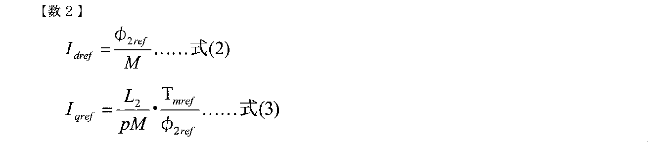
ここで、二次磁束指令φ2refはバッテリ電圧に応じて最適値が変化する。よって直流電圧検出部204から出力された直流電圧203に応じた二次磁束指令φ2refの補正値の算出を行い,その補正値を基にIdref,Iqrefを算出する。
モータ電流検出部209は、電流センサ208により取得したモータ駆動電流データに基づき、誘導電動機108のU相電流IuとW相電流Iwを検出する。座標変換部223は、α軸からd軸までの位相角θdq(電流位相)に基づいて、d軸(励磁)電流Idとq軸(トルク)電流Iqとを分離生成する。位相角θdqの算出方法については後述する。Idは式(4)で,Iqは式(5)で表現される。
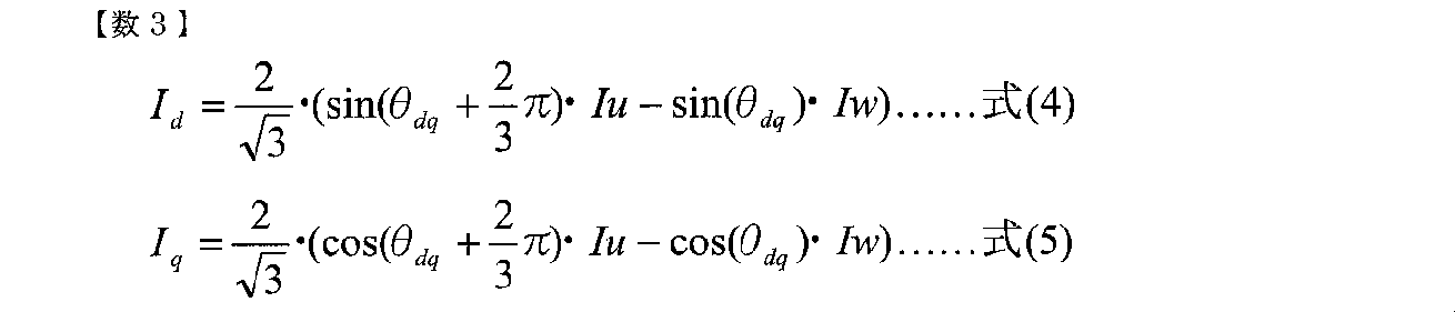
電流FB制御演算部225は、d軸電流指令IdRefとd軸電流Idとが一致するようにd軸電圧指令VdRefを補正する。電流FB制御演算部225は、同様に、q軸電流指令IqRefとq軸電流Iqとが一致するように,q軸電圧指令VqRefを補正する。これらの電圧指令値がFB電圧指令226として出力される。また,電圧FF制御演算部227により一次抵抗の電圧降下と誘起電圧を補償するフィードフォワード制御が行われ、FF電圧指令228として出力される。モータに印加される電圧指令は,このFB電圧指令及びFF電圧指令の和となり,式(6)及び式(7)のように表現される。式(6)、(7)において、L1は一次側自己インダクタンス、σL1は一次漏れインダクタンス、Kpは比例ゲイン、Kiは積分ゲインである。
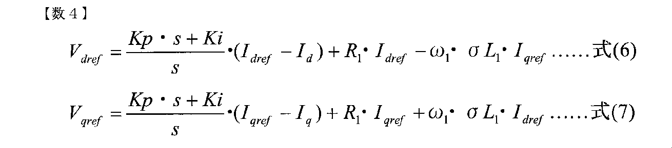
dq軸電圧指令VdRef,VqRefは、座標変換部231において三相電圧指令VuRef,VvRef,VwRefへと変換され、電圧指令230として出力される。Vurefは式(8)で表現され、Vvrefは式(9)で表現され、Vwrefは式(10)で表現される。

PWMデューティ算出部233は、三相電圧指令VuRef,VvRef,VwRefに基づいて、インバータ107内のスイッチング素子に対するゲート指令234を生成し、それをインバータ107へ出力する。なお、このPWM制御は周知の技術であるので、ここではその詳細な説明については省略する。
誘導電動機108にはモータ回転センサ205が備えられている。モータ回転数算出部207は、モータ回転センサ205により取得したデータに基づきモータ回転数ωrを算出する。すべり周波数演算部217は、d軸(励磁)電流指令IdRefとq軸(トルク)電流指令IqRefとに基づいて、すべり周波数基準ωs*を算出する。ωs*は式(11)で表現される。式(11)において、R2は2次抵抗、L2は2次側自己インダクタンスである。

一次周波数演算部219は、インバータ107の出力周波数であって電動機一次周波数であるω1を算出する。ω1は次式(12)で表現される。すなわち、インバータ107の出力周波数が式(12)で算出されるω1に設定される。そして、一次周波数ω1を積分演算部220で積分することにより、図3に示す静止座標系α軸から回転座標系のd軸までの位相角θdq(電流位相)が算出される。

ところで、前述したように、誘導電動機108のトルクTmは、電動機定数に誤差が無く、二次鎖交磁束がd軸に一致した目標動作点において、式(1)により表される。ここで、mは変換係数、Ppは極対数、Mは相互インダクタンス、l2は2次側漏れインダクタンス、φ'は二次鎖交磁束、Iqはq軸電流を示す。

二次鎖交磁束φ'はd軸に一致しているので、座標変換部223から出力されたIdを用いて式(13)で示される。よって、式(1)は次式(14)のように変換できる。

(従来の問題点)
前述したように、Id・Iqは電流検出器208より検出された三相電流値をモータコントローラ108に取り込み、その三相電流値を位相情報(位相角θdq)に基づいて変換することで算出される。モータコントローラ108はデジタル制御により駆動するため、三相電流値の取り込みと電流変換処理を同時に行うことはできず、電流検出の後に変換処理を行いId・Iqを確定させ、そのId・Iqに基づいてトルク推定値算出を行うまでにタイムラグが生じることとなる。
前述したように、Id・Iqは電流検出器208より検出された三相電流値をモータコントローラ108に取り込み、その三相電流値を位相情報(位相角θdq)に基づいて変換することで算出される。モータコントローラ108はデジタル制御により駆動するため、三相電流値の取り込みと電流変換処理を同時に行うことはできず、電流検出の後に変換処理を行いId・Iqを確定させ、そのId・Iqに基づいてトルク推定値算出を行うまでにタイムラグが生じることとなる。
ところで、実際に誘導電動機108に流れる電流の位相はこのタイムラグの間にも変化しているので、算出されたId・Iqと実際のId・Iqとの間にずれが生じるという問題が発生する。
(本実施の形態におけるトルク推定)
図4は、電流検出からId・Iq算出まで(すなわちトルク推定値算出まで)のタイムラグの間に、電流位相がΔθだけ変化した場合の関係を示す図である。図4に示すように、三相電流検出値は、ベクトル制御理論に基づき座標変換を施すと、Id及びIqを成分とする一次電流ベクトルI1として表現される。そのとき、一次電流ベクトルI1は回転座標系d軸に対し位相角θを有し、I1とId、Iqとの間には次式(15)、(16)に示すような関係が成立する。
図4は、電流検出からId・Iq算出まで(すなわちトルク推定値算出まで)のタイムラグの間に、電流位相がΔθだけ変化した場合の関係を示す図である。図4に示すように、三相電流検出値は、ベクトル制御理論に基づき座標変換を施すと、Id及びIqを成分とする一次電流ベクトルI1として表現される。そのとき、一次電流ベクトルI1は回転座標系d軸に対し位相角θを有し、I1とId、Iqとの間には次式(15)、(16)に示すような関係が成立する。

ここで、検出データに基づく一次電流ベクトル検出値I1とタイムラグ後の値である真値I1'との間には、Δθだけの位相のずれがある。そのため、位相角θを用いるとId', Iq'は位相ずれΔθを用いて次式(17)、(18)のように表現できる。

位相ずれΔθが非常に小さい値であると仮定すると、式(17)、(18)は次式(19)、(20)のように近似できる。

よって、上述したトルク推定式(14)は次式(21)のように補正される。

ここで、電流位相は一次周波数ω1で変化するので、電流位相のずれΔθもω1に比例する。よって、位相ずれΔθは次式(22)のように表現できる。

式(22)に含まれる係数C0、C1はモータ駆動システム固有の定数であり、例えば、実測によって決定し、図2のトルク推定部211に予め記憶されている。トルク推定部211は、一次周波数演算部219で算出された一次周波数ω1と式(22)とから位相ずれΔθを算出し、その算出されたΔθと座標変換部223からのId、Iqとに基づいて式(21)に示す補正されたトルク推定値Tmを算出する。算出されたトルク推定値Tmは上位コントローラ110に出力される。
上述した例では、誘導電動機108の駆動状態(力行駆動、回生駆動)によらず所定のC0、C1により位相ずれΔθを算出するようにしているが、誘導電動機108が力行駆動であるか回生駆動であるかによってC0、C1の値が異なる場合がある。そこで、図7に示すようにトルク推定部211にトルク指令Tmrefが入力される構成とし、力行、回生に応じたトルク推定を行うようにする。
図7では、記憶部301に力行駆動用のC01、C11が記憶され、記憶部302に回生駆動用のC02、C12が記憶されている。切換制御部304は、入力されるトルク指令Tmrefが正(力行駆動)の場合には切換部303を記憶部301へ接続し、トルク指令Tmrefが負(回生駆動)の場合には切換部303を記憶部302へ接続する。演算部305は、力行駆動時にはC0=C01、C1=C11を用いてΔθを算出し、そのΔθに基づいてトルク推定値Tmを演算する。また、力行駆動の場合には力行駆動用のC0=C02、C1=C12を用いてΔθを算出し、そのΔθに基づいてトルク推定値Tmを演算する。このような構成とすることで、誘導電動機108の駆動状態に応じたより高精度なトルク推定値を得ることができる。
なお、力行駆動であるか回生駆動であるかによらず同一のC0、C1を用いてΔθを算出するようにしても良い。
また、電流位相のずれΔθを、一次周波数ω1に応じて変化させるのではなく定数としても良い。例えば、定数として一次周波数ω1の平均的な値を採用する。この場合、図1に示すような、トルク推定部211へのω1の入力は必要ない。力行時と回生時とで位相補償量を変える場合には、図7の記憶部301に力行時の位相補償量が記憶され、記憶部302に回生時の位相補償量が記憶される。
図5,6は、モータトルク実測値とモータ制御演算部201で算出されるトルク推定値とを比較したものである。図5は従来のトルク推定値(式(14)で算出したトルク推定値)の場合を示し、図6は本実施の形態のトルク推定値の場合を示す。なお、ここでは、モータ回転数ωrを一定に保ち、モータトルク指令値をランプ状に上昇させるようにした。
いずれの場合も、モータトルク指令の上昇に伴いトルク推定値とトルク実測値との間にずれが生じている。これは、モータトルク指令の上昇により(11)のq軸電流指令IqRefが上昇すると、すべり周波数基準ωs*が増加する。モータ回転数ωrは一定なので、式(12)で算出される一次周波数ω1も増加することになる。トルク推定値とトルク実測値と間のずれ量は一次周波数ω1の大きさに依存するので、モータトルク指令が大きくなるほどずれ量が大きくなる。
図6に示す本実施の形態では、式(21)に示すように、タイムラグに起因する位相ずれΔθに応じてトルク推定値を補正しているので、従来の場合(図5)に比べてトルク推定値とトルク実測値と間のずれ量が小さくなっていることが分かる。
(1)このように、本実施の形態のモータコントローラ109では、駆動周波数であるインバータ107の出力周波数(上記一次周波数ω1)が一次周波数演算部219で設定される。トルク推定部211は、モータ電流検出部209による電流検出からトルク推定までの電流位相変化を補正する位相補償量(例えば式(22)で算出される位相ずれΔθ)と、d軸電流値およびq軸電流値とに基づいて、誘導電動機108の出力トルクTmを推定する。その結果、電流検出からトルク推定値演算までのタイムラグのトルク推定への影響が低減され、トルク推定精度の向上を図ることができる。
上位コントローラ110は、モータコントローラ109で算出されたトルク推定値に基づいて、適切なトルク指令Tmrefおよび二次磁束指令φ2refをモータコントローラ109に入力している。そのため、モータコントローラ109から入力されるトルク推定値の精度向上により、誘導電動機108の駆動状況に応じた適切なトルク指令Tmrefおよび二次磁束指令φ2refをモータコントローラ109に与えることができる。
(2)位相補償量としての位相ずれΔθを、上述の式(22)で算出されるように一次周波数ω1の大きさに応じて変化させるのが好ましい。その結果、時々刻々と変化する一次周波数ω1に応じて位相補償量が変化するので、広範なモータ駆動範囲においてトルク推定値を精度良く行うことができる。また、位相補償量を上述のように定数としても良い。
(3)切換制御部304は、入力されたトルク指令Tmrefに基づいて誘導電動機108の力行および回生を判定する。切換制御部304によって力行と判定されると、トルク推定部211の演算部305は、記憶部301の値C01、C11用いて力行用位相補償量Δθを算出し、その力行用位相補償量Δθに基づいてトルク推定値を算出する。一方、切換制御部304によって回生と判定されると、トルク推定部211の演算部305は、記憶部301の値C02、C12用いて回生用位相補償量Δθを算出し、その回生用位相補償量Δθに基づいてトルク推定値を算出する。
また、位相補償量を定数とする場合、例えば、一次周波数ω1の平均的な値を式(22)のω1とする場合も、力行時と回生時とでC0,C1の値を変更することで、力行時用の定数値および回生時用の定数値が得られる。もちろん、式(22)でω1=0とした場合のΔθを位相補償量としても良い。
その結果、誘導電動機108の駆動状態(力行、回生)に応じた、より正確なトルク推定値を算出することができる。
なお、以上の説明はあくまでも一例であり、発明を解釈する際、上記実施の形態の記載事項と特許請求の範囲の記載事項の対応関係に何ら限定も拘束もされない。また、上述の実施形態では電気自動車を例に説明したが、例えば、ハイブリッド自動車のような電動車両にも適用することができる。
101:電源部、102:モータ駆動部、107:インバータ、108:誘導電動機、109:モータコントローラ、110:上位コントローラ、209:モータ電流検出部、211:トルク推定部、214:電流指令演算部、219:一次周波数演算部、223,230:座標変換部、301,302:記憶部、303:切換部、304:切換制御部、305:演算部
Claims (5)
- 上位コントローラから入力されたトルク指令および二次磁束指令に基づく制御信号を、車両駆動用誘導電動機を高周波駆動するインバータへ出力する制御装置であって、
前記誘導電動機の三相電流値を検出する電流値検出部と、
前記検出された三相電流値をd軸電流値およびq軸電流値に変換する変換部と、
前記誘導電動機の出力トルクを推定するトルク推定部と、を備え、
前記トルク推定部は、前記電流値検出部による電流検出からトルク推定までの電流位相変化を補正する位相補償量と、前記d軸電流値およびq軸電流値とに基づいて、前記出力トルクを推定することを特徴とする制御装置。 - 請求項1に記載の制御装置において、
前記誘導電動機の回転数に基づいて前記インバータの駆動周波数を設定する駆動周波数設定部を備え、
前記トルク推定部は、前記駆動周波数に基づいて前記d軸電流値およびq軸電流値に対する前記位相補償量を算出し、算出された該位相補償量と前記d軸電流値およびq軸電流値とに基づいて前記出力トルクを推定することを特徴とする制御装置。 - 請求項2に記載の制御装置において、
前記トルク指令に基づいて誘導電動機の力行および回生を判定する判定部を備え、
前記トルク推定部は、前記判定部により力行と判定された場合には力行時の前記電流位相変化を補正する第1の位相補償量を算出し、前記判定部により回生と判定された場合には回生時の前記電流位相変化を補正する第2の位相補償量を算出することを特徴とする制御装置。 - 請求項1に記載の制御装置において、
前記位相補償量として一定の値が予め記憶された記憶部を備え、
前記トルク推定部は、前記記憶部に記憶された前記位相補償量と、前記d軸電流値およびq軸電流値とに基づいて前記出力トルクを推定することを特徴とする制御装置。 - 請求項4に記載の制御装置において、
前記トルク指令に基づいて誘導電動機の力行および回生を判定する判定部を備え、
前記記憶部には、力行時の前記電流位相変化を補正する第1の位相補償量と回生時の前記電流位相変化を補正する第2の位相補償量とが予め記憶され、
前記トルク推定部は、前記判定部により力行と判定された場合には前記第1の位相補償量と前記d軸電流値およびq軸電流値とに基づいて前記出力トルクを推定し、前記判定部により回生と判定された場合には前記第2の位相補償量と前記d軸電流値およびq軸電流値とに基づいて前記出力トルクを推定することを特徴とする制御装置。
Applications Claiming Priority (2)
| Application Number | Priority Date | Filing Date | Title |
|---|---|---|---|
| JP2011236127A JP5731355B2 (ja) | 2011-10-27 | 2011-10-27 | 車両駆動用誘導電動機の制御装置 |
| JP2011-236127 | 2011-10-27 |
Publications (1)
| Publication Number | Publication Date |
|---|---|
| WO2013061808A1 true WO2013061808A1 (ja) | 2013-05-02 |
Family
ID=48167641
Family Applications (1)
| Application Number | Title | Priority Date | Filing Date |
|---|---|---|---|
| PCT/JP2012/076567 Ceased WO2013061808A1 (ja) | 2011-10-27 | 2012-10-15 | 車両駆動用誘導電動機の制御装置 |
Country Status (2)
| Country | Link |
|---|---|
| JP (1) | JP5731355B2 (ja) |
| WO (1) | WO2013061808A1 (ja) |
Cited By (2)
| Publication number | Priority date | Publication date | Assignee | Title |
|---|---|---|---|---|
| EP3208138A1 (en) * | 2016-02-17 | 2017-08-23 | ALSTOM Transport Technologies | Method for estimating a torque of an asynchronous electric machine, a torque controller and an electric vehicle |
| CN114244228A (zh) * | 2021-12-14 | 2022-03-25 | 北京国家新能源汽车技术创新中心有限公司 | 基于电机控制器母线电流估算优化方法、系统、存储介质以及计算机 |
Families Citing this family (3)
| Publication number | Priority date | Publication date | Assignee | Title |
|---|---|---|---|---|
| JP6295183B2 (ja) * | 2014-11-06 | 2018-03-14 | 日立オートモティブシステムズ株式会社 | モータ制御装置 |
| JPWO2017122490A1 (ja) * | 2016-01-12 | 2018-08-30 | 日立オートモティブシステムズ株式会社 | モータ制御システム |
| JP7318470B2 (ja) * | 2019-10-03 | 2023-08-01 | 株式会社豊田自動織機 | モデル特性算出装置、モデル特性算出方法、及びプログラム |
Citations (4)
| Publication number | Priority date | Publication date | Assignee | Title |
|---|---|---|---|---|
| JPH07298698A (ja) * | 1994-04-21 | 1995-11-10 | Hitachi Ltd | 誘導モータの制御装置 |
| JP2002291298A (ja) * | 2002-03-25 | 2002-10-04 | Hitachi Ltd | モータ制御装置及び電気車用制御装置 |
| JP2003219697A (ja) * | 2002-01-22 | 2003-07-31 | Railway Technical Res Inst | 誘導電動機制御装置 |
| JP2004112898A (ja) * | 2002-09-18 | 2004-04-08 | Hitachi Ltd | 位置センサレスモータ制御方法および装置 |
Family Cites Families (1)
| Publication number | Priority date | Publication date | Assignee | Title |
|---|---|---|---|---|
| JP2002095105A (ja) * | 2001-07-23 | 2002-03-29 | Hitachi Ltd | 電気自動車の回生制動制御方法および制御装置 |
-
2011
- 2011-10-27 JP JP2011236127A patent/JP5731355B2/ja active Active
-
2012
- 2012-10-15 WO PCT/JP2012/076567 patent/WO2013061808A1/ja not_active Ceased
Patent Citations (4)
| Publication number | Priority date | Publication date | Assignee | Title |
|---|---|---|---|---|
| JPH07298698A (ja) * | 1994-04-21 | 1995-11-10 | Hitachi Ltd | 誘導モータの制御装置 |
| JP2003219697A (ja) * | 2002-01-22 | 2003-07-31 | Railway Technical Res Inst | 誘導電動機制御装置 |
| JP2002291298A (ja) * | 2002-03-25 | 2002-10-04 | Hitachi Ltd | モータ制御装置及び電気車用制御装置 |
| JP2004112898A (ja) * | 2002-09-18 | 2004-04-08 | Hitachi Ltd | 位置センサレスモータ制御方法および装置 |
Cited By (2)
| Publication number | Priority date | Publication date | Assignee | Title |
|---|---|---|---|---|
| EP3208138A1 (en) * | 2016-02-17 | 2017-08-23 | ALSTOM Transport Technologies | Method for estimating a torque of an asynchronous electric machine, a torque controller and an electric vehicle |
| CN114244228A (zh) * | 2021-12-14 | 2022-03-25 | 北京国家新能源汽车技术创新中心有限公司 | 基于电机控制器母线电流估算优化方法、系统、存储介质以及计算机 |
Also Published As
| Publication number | Publication date |
|---|---|
| JP5731355B2 (ja) | 2015-06-10 |
| JP2013094031A (ja) | 2013-05-16 |
Similar Documents
| Publication | Publication Date | Title |
|---|---|---|
| US10418929B2 (en) | Synchronous machine control device and permanent magnet temperature estimation method for synchronous machine | |
| US9350282B2 (en) | Motor control device and motor control method | |
| CN103026615B (zh) | 交流旋转机的控制装置 | |
| CN107710594B (zh) | 交流旋转电机的控制装置及电动助力转向的控制装置 | |
| US20140346983A1 (en) | Motor control device and motor control method | |
| CN107980202A (zh) | 驱动系统以及逆变器装置 | |
| JP5790123B2 (ja) | モータ駆動制御装置とモータ駆動方法 | |
| US9419555B2 (en) | Synchronous machine control apparatus | |
| JP5731355B2 (ja) | 車両駆動用誘導電動機の制御装置 | |
| WO2011070651A1 (ja) | 電力変換装置 | |
| JP7304891B2 (ja) | 回転機の制御装置および電動車両の制御装置 | |
| JP6784061B2 (ja) | 誘導電動機のベクトル制御補償方法とベクトル制御装置 | |
| JP5416183B2 (ja) | 永久磁石同期電動機の制御装置 | |
| JP5278326B2 (ja) | インバータ制御装置及びその制御方法 | |
| JP2009278760A (ja) | モータ制御装置及びモータ制御方法 | |
| JP7151872B2 (ja) | 永久磁石同期機の制御装置 | |
| JP2000037098A (ja) | 速度センサレスベクトル制御を用いた電力変換装置 | |
| JP5726273B2 (ja) | 永久磁石状態推定機能を備えた同期機制御装置およびその方法 | |
| JP2003255006A (ja) | 交流モータの電流センサ故障検知装置 | |
| JP5332305B2 (ja) | 永久磁石形同期電動機の制御装置 | |
| JP5326284B2 (ja) | 同期電動機の制御装置 | |
| JP2009278691A (ja) | 永久磁石形同期電動機の制御装置 | |
| WO2016199444A1 (ja) | 誘導機の電力変換装置と二次時定数測定方法及び速度制御方法 | |
| JP2011045185A (ja) | 永久磁石形同期電動機の制御装置 | |
| JP2005160199A (ja) | 3相交流電動機の制御装置および制御方法 |
Legal Events
| Date | Code | Title | Description |
|---|---|---|---|
| 121 | Ep: the epo has been informed by wipo that ep was designated in this application |
Ref document number: 12843688 Country of ref document: EP Kind code of ref document: A1 |
|
| NENP | Non-entry into the national phase |
Ref country code: DE |
|
| 122 | Ep: pct application non-entry in european phase |
Ref document number: 12843688 Country of ref document: EP Kind code of ref document: A1 |