WO2013061544A1 - ガラス基板及びそれを有するパネルの廃棄処理装置並びにガラス基板及びそれを有するパネルの廃棄処理方法 - Google Patents
ガラス基板及びそれを有するパネルの廃棄処理装置並びにガラス基板及びそれを有するパネルの廃棄処理方法 Download PDFInfo
- Publication number
- WO2013061544A1 WO2013061544A1 PCT/JP2012/006646 JP2012006646W WO2013061544A1 WO 2013061544 A1 WO2013061544 A1 WO 2013061544A1 JP 2012006646 W JP2012006646 W JP 2012006646W WO 2013061544 A1 WO2013061544 A1 WO 2013061544A1
- Authority
- WO
- WIPO (PCT)
- Prior art keywords
- glass substrate
- panel
- liquid
- disposal
- liquid crystal
- Prior art date
- Legal status (The legal status is an assumption and is not a legal conclusion. Google has not performed a legal analysis and makes no representation as to the accuracy of the status listed.)
- Ceased
Links
Images


Classifications
-
- B—PERFORMING OPERATIONS; TRANSPORTING
- B03—SEPARATION OF SOLID MATERIALS USING LIQUIDS OR USING PNEUMATIC TABLES OR JIGS; MAGNETIC OR ELECTROSTATIC SEPARATION OF SOLID MATERIALS FROM SOLID MATERIALS OR FLUIDS; SEPARATION BY HIGH-VOLTAGE ELECTRIC FIELDS
- B03B—SEPARATING SOLID MATERIALS USING LIQUIDS OR USING PNEUMATIC TABLES OR JIGS
- B03B9/00—General arrangement of separating plant, e.g. flow sheets
- B03B9/06—General arrangement of separating plant, e.g. flow sheets specially adapted for refuse
- B03B9/061—General arrangement of separating plant, e.g. flow sheets specially adapted for refuse the refuse being industrial
- B03B9/062—General arrangement of separating plant, e.g. flow sheets specially adapted for refuse the refuse being industrial the refuse being glass
-
- B—PERFORMING OPERATIONS; TRANSPORTING
- B02—CRUSHING, PULVERISING, OR DISINTEGRATING; PREPARATORY TREATMENT OF GRAIN FOR MILLING
- B02C—CRUSHING, PULVERISING, OR DISINTEGRATING IN GENERAL; MILLING GRAIN
- B02C23/00—Auxiliary methods or auxiliary devices or accessories specially adapted for crushing or disintegrating not provided for in preceding groups or not specially adapted to apparatus covered by a single preceding group
- B02C23/18—Adding fluid, other than for crushing or disintegrating by fluid energy
- B02C23/36—Adding fluid, other than for crushing or disintegrating by fluid energy the crushing or disintegrating zone being submerged in liquid
-
- B—PERFORMING OPERATIONS; TRANSPORTING
- B09—DISPOSAL OF SOLID WASTE; RECLAMATION OF CONTAMINATED SOIL
- B09B—DISPOSAL OF SOLID WASTE NOT OTHERWISE PROVIDED FOR
- B09B3/00—Destroying solid waste or transforming solid waste into something useful or harmless
- B09B3/30—Destroying solid waste or transforming solid waste into something useful or harmless involving mechanical treatment
- B09B3/35—Shredding, crushing or cutting
-
- Y—GENERAL TAGGING OF NEW TECHNOLOGICAL DEVELOPMENTS; GENERAL TAGGING OF CROSS-SECTIONAL TECHNOLOGIES SPANNING OVER SEVERAL SECTIONS OF THE IPC; TECHNICAL SUBJECTS COVERED BY FORMER USPC CROSS-REFERENCE ART COLLECTIONS [XRACs] AND DIGESTS
- Y02—TECHNOLOGIES OR APPLICATIONS FOR MITIGATION OR ADAPTATION AGAINST CLIMATE CHANGE
- Y02W—CLIMATE CHANGE MITIGATION TECHNOLOGIES RELATED TO WASTEWATER TREATMENT OR WASTE MANAGEMENT
- Y02W30/00—Technologies for solid waste management
- Y02W30/50—Reuse, recycling or recovery technologies
- Y02W30/52—Mechanical processing of waste for the recovery of materials, e.g. crushing, shredding, separation or disassembly
-
- Y—GENERAL TAGGING OF NEW TECHNOLOGICAL DEVELOPMENTS; GENERAL TAGGING OF CROSS-SECTIONAL TECHNOLOGIES SPANNING OVER SEVERAL SECTIONS OF THE IPC; TECHNICAL SUBJECTS COVERED BY FORMER USPC CROSS-REFERENCE ART COLLECTIONS [XRACs] AND DIGESTS
- Y02—TECHNOLOGIES OR APPLICATIONS FOR MITIGATION OR ADAPTATION AGAINST CLIMATE CHANGE
- Y02W—CLIMATE CHANGE MITIGATION TECHNOLOGIES RELATED TO WASTEWATER TREATMENT OR WASTE MANAGEMENT
- Y02W30/00—Technologies for solid waste management
- Y02W30/50—Reuse, recycling or recovery technologies
- Y02W30/60—Glass recycling
Definitions
- the present invention relates to a glass substrate and a disposal device for a panel having the glass substrate, and a glass substrate and a disposal method for the panel having the glass substrate.
- liquid crystal panels that have become unnecessary in the liquid crystal panel manufacturing process have been crushed to a large size by primary crushing, and then secondarily crushed to a small size of about 5 mm and collected. ing.
- Patent Document 1 in a liquid crystal panel disposal method that disposes of a liquid crystal panel that is no longer needed, the liquid crystal panel is crushed with at least liquid crystal contained, and glass cullet that is crushed waste is recycled. Things are known.
- the present invention has been made in view of the above points, and the object of the present invention is to keep a clean environment by preventing shattered and refined environmental pollutants such as glass cullet and liquid crystal material from scattering. There is.
- the glass substrate or the panel having the glass substrate is crushed while applying the liquid, or is crushed in the liquid.
- the waste disposal device A transport device for carrying in the glass substrate or a panel having the glass substrate; A liquid ejection device for ejecting liquid onto the glass substrate or a panel having the glass substrate; A panel crusher for crushing the glass substrate in a state where the liquid is discharged or a panel having the glass substrate; There is provided a crushed object collecting device for separating the pulverized glass substrate or the panel having the pulverized glass substrate from the liquid and collecting the pulverized object.
- a panel having a glass substrate refers to a panel for liquid crystal display (liquid crystal panel), a panel for organic EL display, a panel for plasma display, a panel for thin film solar cell, etc., and the glass substrate is a plate glass used for it.
- the liquid ejection device has an upstream nozzle disposed on the upstream side of the panel crushing device, and a downstream nozzle disposed on the downstream side of the panel crushing device,
- the upstream nozzle discharges the liquid so as to spread over a wide range on both surfaces of the glass substrate or the panel having the glass substrate,
- the downstream nozzle is configured to eject the liquid more strongly than the upstream nozzle in the form of water droplets.
- the above-mentioned disposal processing equipment is A liquid reservoir in which liquid is stored; A transport device for carrying the glass substrate or a panel having the glass substrate into the liquid storage unit; A panel crusher for crushing the glass substrate or a panel having the glass substrate in the liquid reservoir; There is provided a crushed object collecting device for separating the pulverized glass substrate or the panel having the pulverized glass substrate from the liquid and collecting the pulverized object.
- the glass substrate or the panel having the glass substrate is crushed in the liquid, environmental pollutants such as liquid crystal material flow into the liquid, and the fine glass cullet does not jump out of the liquid. Since the glass cullet is separated and collected from a liquid containing an environmental pollutant such as a liquid crystal material, the glass cullet can be easily recycled.
- recovery apparatus is set as the structure containing a wire-mesh-like conveyor.
- the glass cullet can be taken out while removing the adhered liquid by an appropriate vibration while conveying the crushed glass cullet, it is easy to recycle the glass cullet.
- the liquid is pure water.
- pure water is advantageous because it does not pollute the clean environment even if it is mist or vaporized during discharge and leaks to the surroundings.
- the glass substrate and the disposal method of the panel having the glass substrate are as follows: Crushing while applying a liquid to the glass substrate or a panel having the glass substrate; Separating and recovering the pulverized material to be crushed; And a step of recovering the separated liquid.
- the fine glass cullet is surely scattered or floated compared with the case where the glass substrate is not wetted with the liquid. To be prevented. Environmental pollutants such as liquid crystal materials are washed away by the liquid and do not scatter. Moreover, it does not pollute the global environment by collecting the separated liquid.
- the liquid Before crushing the glass substrate or a panel having the glass substrate, the liquid is discharged so as to spread over a wide range on both surfaces of the glass substrate or the panel having the glass substrate. It is set as the structure discharged toward a ground material.
- the premise glass substrate and the disposal method of the panel having the glass substrate are as follows: Crushing the glass substrate or a panel having the glass substrate while being immersed in a liquid; Separating and recovering the pulverized material to be crushed; And a step of recovering the separated liquid.
- the glass substrate or the panel having the glass substrate is crushed in the liquid, environmental pollutants such as liquid crystal material flow into the liquid, and the fine glass cullet is scattered or floated. Is reliably prevented. Since the glass cullet is separated and collected from the liquid containing the environmental pollutant such as the liquid crystal material, the glass cullet from which the environmental pollutant such as the liquid crystal material is removed can be easily recycled. Moreover, it does not pollute the global environment by collecting the separated liquid.
- the liquid is pure water.
- pure water is advantageous because it does not pollute the clean environment even if it is mist or vaporized during discharge and leaks to the surroundings.
- the glass substrate or a panel having the glass substrate is wetted with liquid before crushing, or the glass substrate or the panel having the glass substrate is crushed in the liquid to be crushed and refined.
- a clean environment can be maintained by preventing scattering of environmental pollutants such as glass cullet and liquid crystal material.
- environmental pollutants such as glass cullet and liquid crystal material.
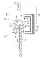
- FIG. 1 is a front view illustrating an outline of a liquid crystal panel disposal apparatus according to a first embodiment.
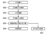
- 3 is a flowchart illustrating an outline of a liquid crystal panel disposal method according to the first embodiment. It is a front view which shows the outline of the disposal processing apparatus of the liquid crystal panel concerning Embodiment 2.
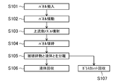
- 6 is a flowchart illustrating an outline of a liquid crystal panel disposal method according to a second embodiment; It is a front view which shows the outline of the disposal processing apparatus of the liquid crystal panel concerning Embodiment 3.
- 12 is a flowchart illustrating an outline of a liquid crystal panel disposal method according to a third embodiment.
- FIG. 1 shows a disposal device 10 for a liquid crystal panel 1 according to Embodiment 1 of the present invention, and this disposal device 10 includes a transport device 11 for carrying the liquid crystal panel 1.
- the transport device 11 is a general substrate transport roller transport device, but may be a belt conveyor or the like.
- the waste treatment apparatus 10 further includes a liquid ejection apparatus 12 that ejects liquid (in this embodiment, pure water is circulated and includes some foreign matter by circulation) to the liquid crystal panel 1.
- the liquid ejection device 12 includes an upstream nozzle 12 a disposed on the upstream side of a panel pulverizing device 13 described later, and a downstream nozzle 12 b disposed on the downstream side of the panel pulverizing device 13.
- the upstream nozzle 12a and the downstream nozzle 12b are arranged in the entire width direction of the liquid crystal panel 1 and are connected to the water pipe 12c.
- the water in the water pipe 12c is pressurized by a pressurizing device (not shown). It comes to be supplied in the state.
- the upstream nozzle 12a is disposed only on the upper surface side of the liquid crystal panel 1 in FIG. 1, it may also be disposed on the lower surface side to discharge the liquid so as to spread over a wide range on both surfaces. Further, the downstream nozzle 12b is configured to discharge liquid more strongly than the upstream nozzle 12a in the form of water droplets.
- the liquid may be alcohol-based or oil-based, but pure water is desirable for preventing contamination in a clean environment.
- the disposal apparatus 10 further includes a panel crusher 13 that crushes the liquid crystal panel 1 in a state where the liquid is discharged.
- the panel crusher 13 includes, for example, a roller 13a having a large number of protrusions 13b arranged on the upper and lower sides of the liquid crystal panel 1 so as to extend in the entire width direction thereof, and sandwiches the liquid crystal panel 1, for example, about 100 mm ⁇ 100 mm. It is configured to be pulverized to a size that can be easily conveyed.
- a crushed object collecting device 14 that separates and collects the pulverized material 2 such as glass cullet that has been crushed and separated from the liquid.
- recovery apparatus 14 contains, when the bottom plate 14a consists of a metal mesh etc., for example, the collection container 14b of the shape, and when this collection container 14b isolate
- a vibration device (not shown) may be provided in the collection container 14b to forcibly vibrate so that the water droplets can be easily dropped.
- the waste processing apparatus 10 includes a waste liquid recovery apparatus 15 that recovers the separated liquid.
- the waste liquid recovery device 15 includes, for example, a liquid tank 15a larger than the recovery container 14b.
- a drain pipe 15b is connected to the bottom plate of the liquid tank 15a, and a water pipe 12c is connected to the drain pipe 15b via a filter 15c. It is connected.
- the filter 15c may be selected according to the type of liquid, and the plurality of filters 15c may be provided in any number of stages.
- step S01 the liquid crystal panel 1 that has become unnecessary after the examination of the trial production or the like is carried into the transport device 11. Then, the liquid crystal panel 1 proceeds on the transport device 11 toward the panel crusher 13.
- step S02 both sides of the liquid crystal panel 1 are wetted over a wide range by the liquid ejected from the upstream nozzle 12a before the panel crusher 13.
- step S03 the liquid crystal panel 1 whose both surfaces are moderately wetted is pulverized by the protrusions 13b of the panel pulverizing apparatus 13. At this time, it is possible to avoid scattering of glass dust by wetting the liquid crystal panel 1 with liquid before crushing.
- step S04 the liquid ejected in the form of water droplets from the downstream nozzle 12b on the discharge side of the panel crusher 13 also rinses away environmental pollutants such as liquid crystal material adhering to the glass cullet.
- step S05 the object to be crushed 2 falls onto the collection container 14b together with the adhering liquid, and the object to be pulverized 2 that is a solid remains on the wire net-like bottom plate 14a, and the liquid falls freely or If there is a vibration device, it is dropped by vibration and collected in the liquid tank 15a.
- step S06 the collected liquid is sucked up through the drain pipe 15b and filtered through the filter 15c.
- the filter 15c environmental pollutants such as powdery glass and liquid crystal material mixed in the liquid are collected.
- the liquid that has passed through the filter 15c is sent again to the upstream nozzle 12a and the downstream nozzle 12b through the water pipe 12c.
- step S07 the glasslets collected in the collection container 14b are carried out and recycled. Since the glass cullet is collected separately from the liquid, the glass cullet from which environmental pollutants such as liquid crystal materials are removed can be easily recycled.
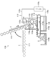
- FIG. 3 shows a disposal apparatus 110 for the liquid crystal panel 1 according to the second embodiment of the present invention.
- the same portions as those in FIGS. 1 and 2 are denoted by the same reference numerals, and detailed description thereof is omitted.
- the transport device 111 is configured to be tiltable.
- the transport device 111 is tilted, and the liquid crystal panel 1 is sent to the panel crusher 113 in a tilted state.
- the upstream nozzle 112a of the liquid ejection device 112 is disposed only on the upper surface side of the liquid crystal panel 1, but is desirably disposed on the lower surface side.
- the liquid supplied from the water pipe 112c wets both surfaces of the liquid crystal panel 1 over a wide range, and the liquid not attached to the liquid crystal panel 1 is collected by the funnel 112d and extends in the width direction of the liquid crystal panel 1. It falls as water droplets from the opening 112e.
- the panel crusher 113 is disposed directly below the opening 112e, and the liquid that has fallen is configured to fall on the panel crusher 113. Therefore, no nozzle is disposed on the downstream side, but on the downstream side. May also be provided.
- the object to be crushed 2 that has fallen along with the water droplets is configured to be collected by the object to be crushed recovery apparatus 114 including the wire mesh conveyor 114a.
- the to-be-ground object 2 from which the liquid has been removed by the wire mesh conveyor 114a is recovered in the recovery container 114b, while the liquid falling downward is recovered in the liquid tank 115a of the waste liquid recovery device 115. .
- step S 101 the liquid crystal panel 1 that is no longer necessary is carried into the transport device 111 and temporarily stopped before the panel crusher 113.
- step S102 the transport device 111 is tilted, and the liquid crystal panel 1 is carried into the funnel 112d by its own weight or automatically.
- step S103 both surfaces of the liquid crystal panel 1 are wetted with the liquid discharged over a wide range from the upstream nozzle 112a above the funnel 112d.
- step S104 the liquid crystal panel 1 sandwiched between the rollers 113a is crushed by the protrusions 113b. At this time, since the roller 113a is wet with the water droplets falling by the funnel 112d, the dust prevention effect is further improved.
- step S105 the object to be crushed 2 falls on the wire mesh conveyor 114a together with the adhering liquid, and the liquid is efficiently separated by vibration when traveling on the wire mesh conveyor 114a.
- the object 2 to be crushed remains on the wire mesh conveyor 114a, and the liquid is collected in the liquid tank 115a.
- step S106 the collected liquid is sucked up through the drain pipe 115b and filtered through the filter 115c.
- the liquid that has passed through the filter 115c is sent again to the upstream nozzle 112a side through the water pipe 112c.
- step S107 the glasslets collected in the collection container 114b are carried out and recycled.
- environmental pollutants such as glass cullet and liquid crystal material that are crushed and refined are scattered by wetting the liquid crystal panel 1 with liquid before crushing. Can be kept clean environment.
- the glass cullet can be carried out while removing the liquid of the crushed glass cullet with the wire mesh conveyor 114a, the glass cullet can be recycled very efficiently.
- FIG. 5 shows a disposal apparatus 210 for the liquid crystal panel 1 according to the third embodiment of the present invention, which differs from the first and second embodiments mainly in that the method of attaching the liquid to the liquid crystal panel 1 is different.
- the disposal apparatus 210 includes a liquid storage unit 212 in which a liquid such as pure water is stored.
- the liquid storage unit 212 may discharge the dirty liquid through a discharge pipe (not shown), filter it with a filter, and circulate it again in the liquid storage unit 212.
- the disposal apparatus 210 includes a transport device 211 that carries the liquid crystal panel 1 into the liquid storage unit 212.
- the transport device 211 is inclined downward, and the front end side in the traveling direction is immersed in the liquid in the liquid storage unit 212.
- a panel crusher 213 that crushes the liquid crystal panel 1 is disposed so that at least a part of the apparatus is submerged.
- This panel crusher 213 may have the same configuration as that of each of the above embodiments, but is characterized in that a portion sandwiching the liquid crystal panel 1 is in the liquid. For this reason, it is not necessary to provide the liquid ejection devices 12 and 112, and the configuration is simple.
- the disposal apparatus 210 further includes a pulverized object collecting apparatus 214 that separates the pulverized liquid crystal panel 1 from the liquid and collects the pulverized object 2.
- the object to be crushed recovery device 214 includes a wire mesh conveyor 214a, and this wire mesh conveyor 214a carries the object to be crushed 2 made of glass cullet falling in the liquid upward from the liquid surface to separate the liquid. In this state, it is configured to drop onto the recovery container 214b.
- step S 201 the liquid crystal panel 1 that is no longer necessary is carried into the transport device 211.
- step S202 the liquid crystal panel 1 is gradually immersed in the liquid in the liquid storage unit 212 from the front end side.
- step S203 the liquid crystal panel 1 sandwiched between the rollers 213a in the liquid is crushed by the protrusions 213b.
- the specific gravity of glass is about 2.5
- the specific gravity of water is larger than 1.0
- the glass cullet falls in the liquid and is carried out of the liquid by the wire mesh conveyor 214a.
- environmental pollutants such as fine glass cullet and liquid crystal material are stored in the liquid without being carried out by the wire mesh conveyor 214a, they are surely prevented from leaking into the air.
- step S204 the object to be crushed 2 is carried out from the liquid surface by the wire mesh conveyor 214a together with the adhering liquid, and the liquid is separated by vibration or the like when further proceeding on the wire mesh conveyor 214a.
- the object 2 to be crushed remains on the wire mesh conveyor 214 a, and the liquid returns to the liquid reservoir 212.
- step S205 the glasslets collected in the collection container 214b are carried out and recycled.
- the disposal method of the liquid crystal panel 1 according to the present embodiment since the liquid crystal panel 1 is crushed in the liquid, environmental pollutants such as glass cullet and liquid crystal material are scattered or floated. It is surely prevented. Since the glass cullet is collected separately from the liquid, the glass cullet from which environmental pollutants such as liquid crystal materials are removed can be easily recycled.
- the present invention may be configured as follows with respect to the above embodiment.
- the object to be crushed is limited to the liquid crystal panel 1, but a single glass substrate used for the liquid crystal panel 1 may be used, and an organic EL display panel, a plasma display panel, a thin film solar cell may be used. A glass panel alone or a glass substrate used for them can be similarly crushed.
- the liquid is pure water, but it may be an organic solvent such as acetone. In this case, it is effective when removing environmental pollutants that are not water-soluble from the glass cullet.
- the liquid discharging method is ejected vigorously from the nozzle, but the liquid momentum may be weak and may be ejected so as to spill.
- the present invention is useful for a disposal device for a liquid crystal panel that discards a glass substrate and a panel having the glass substrate, and a disposal method for the glass substrate and the panel having the glass substrate.
Landscapes
- Engineering & Computer Science (AREA)
- Environmental & Geological Engineering (AREA)
- Food Science & Technology (AREA)
- Processing Of Solid Wastes (AREA)
Abstract
液晶パネル(1)を廃棄処理する液晶パネル(1)の廃棄処理装置(10)において、液晶パネル(1)を搬入する搬送装置(11)と、液晶パネル(1)に液体を吐出する液体吐出装置(12)と、液体が吐出された状態の液晶パネル(1)を粉砕するパネル粉砕装置(13)と、粉砕された液晶パネル(1)を液体と分離させて被粉砕物を回収する被粉砕物回収装置(14)とを設ける。これにより、液体吐出装置(12)によって液晶パネル(1)に液体をかけながら粉砕し、粉砕された被粉砕物(2)を液体と分離して回収する。
Description
本発明は、ガラス基板及びそれを有するパネルの廃棄処理装置並びにガラス基板及びそれを有するパネルの廃棄処理方法に関するものである。
従来より、液晶パネルの製造工程において、試作等検討が終了して不要となった液晶パネルを一次破砕で大きいサイズに破砕し、その後、二次破砕して5mm程度の小さいサイズに破砕し回収している。
例えば、特許文献1のように、不要になった液晶パネルを廃棄処理する液晶パネルの廃棄処理方法において、少なくとも液晶が入った状態で液晶パネルを破砕し、破砕屑であるガラスカレットをリサイクル処理するものが知られている。
しかしながら、上記特許文献1のような廃棄処理方法では、微細化したガラスカレット等が飛散してパーティションの隙間、壁の開口等から漏れだし、クリーン環境が汚染されるという問題がある。
そこで、廃棄処理装置の周囲を陰圧に保ち、周囲へ気流吹き出しが起こらないようにすることも考えられるが、液晶パネルを搬出入するロボットや人の出入りがあるので、微細化したガラスカレット等の外部への流出を完全に防ぐことはできない。
また、特許文献1の方法では、微細化したガラスカレットに、環境汚染が懸念される化学物質や有機物、化合物(以下、環境汚染物質という)が付着したまま粉塵として飛散し、周囲を汚染するという問題があった。
本発明は、かかる点に鑑みてなされたものであり、その目的とするところは、破砕して微細化したガラスカレットや液晶材料等の環境汚染物質が飛散するのを防いでクリーンな環境を保つことにある。
上記の目的を達成するために、この発明では、ガラス基板又はそれを有するパネルに液体をかけながら破砕し、又は液体中で破砕するようにした。
具体的には、第1の発明では、ガラス基板及びそれを有するパネルの廃棄処理装置を前提とし、
上記廃棄処理装置は、
上記ガラス基板又はそれを有するパネルを搬入する搬送装置と、
上記ガラス基板又はそれを有するパネルに液体を吐出する液体吐出装置と、
上記液体が吐出された状態の上記ガラス基板又はそれを有するパネルを粉砕するパネル粉砕装置と、
上記粉砕されたガラス基板又はそれを有するパネルを液体と分離させて被粉砕物を回収する被粉砕物回収装置とを備えている。
上記廃棄処理装置は、
上記ガラス基板又はそれを有するパネルを搬入する搬送装置と、
上記ガラス基板又はそれを有するパネルに液体を吐出する液体吐出装置と、
上記液体が吐出された状態の上記ガラス基板又はそれを有するパネルを粉砕するパネル粉砕装置と、
上記粉砕されたガラス基板又はそれを有するパネルを液体と分離させて被粉砕物を回収する被粉砕物回収装置とを備えている。
上記の構成によると、破砕前にガラス基板又はそれを有するパネルを液体で濡らすことにより、液体で濡らさない場合に比べ、微細なガラスカレットが飛散したり、浮遊したりするのが確実に防止される。液晶材料等の環境汚染物質は、液体により洗い流されるので、飛散しない。なお、以下、ガラス基板を有するパネルとは、液晶ディスプレイ用パネル(液晶パネル)、有機ELディスプレイ用パネル、プラズマディスプレイ用パネル、薄膜太陽電池用パネル等をいい、ガラス基板は、それに利用される板ガラスをいう。特にガラス基板を有するパネルであれば、ガラス成分だけでなく、液晶などの環境汚染物質を液体により洗い流す効果が発揮される。
第2の発明では、第1の発明において、
上記液体吐出装置は、パネル粉砕装置の上流側に配置された上流側ノズルと、パネル粉砕装置の下流側に配置された下流側ノズルとを有し、
上記上流側ノズルは、上記ガラス基板又はそれを有するパネルの両面の広範囲に広がるように上記液体を吐出し、
上記下流側ノズルは、水滴状に上記上流側ノズルよりも強く上記液体を吐出するように構成されている。
上記液体吐出装置は、パネル粉砕装置の上流側に配置された上流側ノズルと、パネル粉砕装置の下流側に配置された下流側ノズルとを有し、
上記上流側ノズルは、上記ガラス基板又はそれを有するパネルの両面の広範囲に広がるように上記液体を吐出し、
上記下流側ノズルは、水滴状に上記上流側ノズルよりも強く上記液体を吐出するように構成されている。
上記の構成によると、破砕前のガラス基板又はそれを有するパネルの両面に液体を付着させることで、ガラスカレットや液晶材料等の環境汚染物質が飛散したり、浮遊したりするのが確実に防止される。そして、破砕後の飛散又は浮遊しようとする微細化したガラスカレットが水滴に付着して落下する。液晶材料等の環境汚染物質は、液体に洗い流される。ガラスカレットは、液晶材料等の環境汚染物質を含む液体と分離されて回収されるので、液晶材料等の環境汚染物質が除かれたガラスカレットのリサイクルが容易となる。
第3の発明では、
上記前提の廃棄処理装置は、
液体が貯留された液体貯留部と、
上記液体貯留部に上記ガラス基板又はそれを有するパネルを搬入する搬送装置と、
上記液体貯留部内で上記ガラス基板又はそれを有するパネルを粉砕するパネル粉砕装置と、
上記粉砕されたガラス基板又はそれを有するパネルを液体と分離させて被粉砕物を回収する被粉砕物回収装置とを備えている。
上記前提の廃棄処理装置は、
液体が貯留された液体貯留部と、
上記液体貯留部に上記ガラス基板又はそれを有するパネルを搬入する搬送装置と、
上記液体貯留部内で上記ガラス基板又はそれを有するパネルを粉砕するパネル粉砕装置と、
上記粉砕されたガラス基板又はそれを有するパネルを液体と分離させて被粉砕物を回収する被粉砕物回収装置とを備えている。
上記の構成によると、液体中でガラス基板又はそれを有するパネルが破砕されるので、液晶材料等の環境汚染物質は、液体中に流れ出し、細かいガラスカレットは液体内から飛び出さない。ガラスカレットは、液晶材料等の環境汚染物質を含む液体と分離されて回収されるので、ガラスカレットのリサイクルが容易となる。
第4の発明では、第1乃至第3のいずれか1つの発明において、
上記被粉砕物回収装置は、金網状コンベアを含む構成とする。
上記被粉砕物回収装置は、金網状コンベアを含む構成とする。
上記の構成によると、破砕後のガラスカレットを搬送しながら適度な振動により、付着した液体を取り除きつつガラスカレットを搬出できるので、ガラスカレットのリサイクルが容易となる。
第5の発明では、第1乃至第4のいずれか1つの発明において、
上記液体は、純水である。
上記液体は、純水である。
上記の構成によると、純水であれば、吐出時にミスト化又は気化して周囲へ漏れ出したとしても、クリーン環境を汚染することはないので、有利である。
第6の発明では、ガラス基板及びそれを有するパネルの廃棄処理方法を前提とし、
上記ガラス基板及びそれを有するパネルの廃棄処理方法は、
上記ガラス基板又はそれを有するパネルに液体をかけながら粉砕する工程と、
上記粉砕された被粉砕物を液体と分離して回収する工程と、
上記分離された液体を回収する工程とを含む構成とする。
上記ガラス基板及びそれを有するパネルの廃棄処理方法は、
上記ガラス基板又はそれを有するパネルに液体をかけながら粉砕する工程と、
上記粉砕された被粉砕物を液体と分離して回収する工程と、
上記分離された液体を回収する工程とを含む構成とする。
上記の構成によると、破砕前又は破砕中にガラス基板又はそれを有するパネルを液体で濡らすことにより、液体で濡らさない場合に比べ、微細なガラスカレットが飛散したり、浮遊したりするのが確実に防止される。液晶材料等の環境汚染物質は、液体により洗い流されるので、飛散しない。また、分離された液体を回収することで地球環境を汚さない。
第7の発明では、第6の発明において、
上記ガラス基板又はそれを有するパネルを粉砕する前に上記ガラス基板又はそれを有するパネルの両面の広範囲に広がるように上記液体を吐出し、粉砕中又は粉砕後には、水滴状により強く上記液体を被粉砕物に向かって吐出する構成とする。
上記ガラス基板又はそれを有するパネルを粉砕する前に上記ガラス基板又はそれを有するパネルの両面の広範囲に広がるように上記液体を吐出し、粉砕中又は粉砕後には、水滴状により強く上記液体を被粉砕物に向かって吐出する構成とする。
上記の構成によると、破砕前のガラス基板又はそれを有するパネルの両面に液体を付着させることで、ガラスカレットや液晶材料等の環境汚染物質が飛散したり、浮遊したりするのが確実に防止される。そして、破砕後の飛散、浮遊しようとする微細化したガラスカレットが水滴に付着して落下する。ガラスカレットは、液晶材料等の環境汚染物質を含む液体と分離されて回収されるので、液晶材料等の環境汚染物質が除かれたガラスカレットのリサイクルが容易となる。
第8の発明では、
上記前提のガラス基板及びそれを有するパネルの廃棄処理方法は、
上記ガラス基板又はそれを有するパネルを液体中に浸しながら粉砕する工程と、
上記粉砕された被粉砕物を液体と分離して回収する工程と、
上記分離された液体を回収する工程とを含む構成とする。
上記前提のガラス基板及びそれを有するパネルの廃棄処理方法は、
上記ガラス基板又はそれを有するパネルを液体中に浸しながら粉砕する工程と、
上記粉砕された被粉砕物を液体と分離して回収する工程と、
上記分離された液体を回収する工程とを含む構成とする。
上記の構成によると、液体中でガラス基板又はそれを有するパネルが破砕されるので、液晶材料等の環境汚染物質が液中に流れ出し、かつ微細なガラスカレットが飛散したり、浮遊したりするのが確実に防止される。ガラスカレットは、液晶材料等の環境汚染物質を含む液体と分離されて回収されるので、液晶材料等の環境汚染物質が除かれたガラスカレットのリサイクルが容易となる。また、分離された液体を回収することで地球環境を汚さない。
第9の発明では、第6乃至8のいずれか1つの発明において、
上記液体は純水である。
上記液体は純水である。
上記の構成によると、純水であれば、吐出時にミスト化又は気化して周囲へ漏れ出したとしても、クリーン環境を汚染することはないので、有利である。
以上説明したように、本発明によれば、破砕前にガラス基板又はそれを有するパネルを液体で濡らしたり、液中でガラス基板又はそれを有するパネルを破砕することにより、破砕して微細化したガラスカレットや液晶材料等の環境汚染物質が飛散するのを防いでクリーンな環境を保つことができる。その結果として、ガラス基板又はそれを有するパネルの製造工程における、異物の付着等による不良発生を抑制することができ、歩留まりが向上する。
以下、本発明の実施形態を図面に基づいて説明する。
(実施形態1)
-液晶パネルの廃棄処理装置の構成-
図1は本発明の実施形態1の液晶パネル1の廃棄処理装置10を示し、この廃棄処理装置10は、液晶パネル1を搬入する搬送装置11を備えている。本実施形態では、搬送装置11は、一般的な基板搬送用ローラ搬送装置とするが、ベルトコンベア等でもよい。
-液晶パネルの廃棄処理装置の構成-
図1は本発明の実施形態1の液晶パネル1の廃棄処理装置10を示し、この廃棄処理装置10は、液晶パネル1を搬入する搬送装置11を備えている。本実施形態では、搬送装置11は、一般的な基板搬送用ローラ搬送装置とするが、ベルトコンベア等でもよい。
廃棄処理装置10は、さらに、液晶パネル1に液体(本実施形態では、純水を循環させたものであって、循環することで、ある程度の異物は含まれる)を吐出する液体吐出装置12を備えている。液体吐出装置12は、後述するパネル粉砕装置13の上流側に配置された上流側ノズル12aと、パネル粉砕装置13の下流側に配置された下流側ノズル12bとを有する。これら上流側ノズル12a及び下流側ノズル12bは、液晶パネル1の幅方向全体に配置されていると共に、水配管12cに接続され、この水配管12c内の水が図示しない加圧装置により加圧された状態で供給されるようになっている。上流側ノズル12aは、図1では、液晶パネル1の上面側にしか配置していないが、下面側にも配置し、両面の広範囲に広がるように液体を吐出するようにしてもよい。また、下流側ノズル12bは、水滴状に上流側ノズル12aよりも強く液体を吐出するように構成されている。液体としては、アルコール系やオイル系でもよいが、クリーン環境の汚染防止には、純水が望ましい。
廃棄処理装置10は、さらに、液体が吐出された状態の液晶パネル1を粉砕するパネル粉砕装置13を備えている。パネル粉砕装置13は、例えば、液晶パネル1の上下に、その幅方向全体に延びるように配置された、多数の突起13bを有するローラ13aを備え、液晶パネル1を挟み込んで例えば100mm×100mm程度の搬送容易なサイズに粉砕可能に構成されている。
このパネル粉砕装置13の下方には、粉砕されて小さくなったガラスカレットなどの被粉砕物2を液体と分離させて回収する被粉砕物回収装置14が配置されている。この被粉砕物回収装置14は、例えば底板14aが金網等よりなる、ざる状の回収容器14bを含み、この回収容器14bで被粉砕物2から液体が分離され、ガラスカレットが所定量溜まったときにロボットやクレーンで回収できるようになっている。なお、回収容器14bに図示しない振動装置を設けて強制的に振動させて水滴を落ちやすくしてもよい。
そして、廃棄処理装置10は、分離された液体を回収する廃液回収装置15を備えている。廃液回収装置15は、例えば、回収容器14bよりも大きな液体タンク15aを備え、この液体タンク15aの底板には、排水管15bが接続され、この排水管15bにフィルタ15cを介して水配管12cが接続されている。フィルタ15cは、液体の種類に合わせて選択すればよく、複数のフィルタ15cを何段階に分けて設けてもよい。
-液晶パネルの廃棄処理方法-
次に、本実施形態にかかる液晶パネル1の廃棄処理方法について図2を用いて説明する。
次に、本実施形態にかかる液晶パネル1の廃棄処理方法について図2を用いて説明する。
まず、ステップS01において、試作等の検討後、不要となった液晶パネル1を搬送装置11に搬入する。すると、液晶パネル1は、搬送装置11上をパネル粉砕装置13に向かって進む。
次いで、ステップS02において、パネル粉砕装置13の手前で上流側ノズル12aから噴出された液体によって液晶パネル1の両面を広範囲にわたって濡らす。
次いで、ステップS03において、両面が適度に濡らされた液晶パネル1をパネル粉砕装置13の突起13bで粉砕する。このとき、破砕前に液晶パネル1を液体で濡らすことにより、ガラスの粉塵が飛び散ることが避けられる。
しかも、ステップS04において、パネル粉砕装置13の排出側で下流側ノズル12bから水滴状に噴出された液体により、ガラスカレットに付着した液晶材料等の環境汚染物質も洗い流されると共に、破砕後の飛散及び浮遊しようとする微細化したガラスカレットが水滴と共に落下する。上流側ノズル12a及び下流側ノズル12bから噴出された液体は、純水であるので、吐出時にミスト化又は気化して周囲へ漏れ出したとしても、クリーン環境を汚染することはない。
次いで、ステップS05において、被粉砕物2は、付着した液体と共に回収容器14b上に落下し、金網状の底板14aには、固体である被粉砕物2が残り、液体は、自由落下して又は振動装置がある場合には振動により落下して液体タンク15aに回収される。
次いで、ステップS06において、回収された液体は、排水管15bを通って吸い上げられ、フィルタ15cで濾過される。フィルタ15cにおいて、液体内に混在する粉状のガラス、液晶材料等の環境汚染物質が回収される。フィルタ15cを通った液体は、水配管12cを通って上流側ノズル12a及び下流側ノズル12b側へ再び送られる。
一方、ステップS07において、回収容器14bに回収されたガラスレット等を搬出し、リサイクルする。ガラスカレットは、液体と分離されて回収されるので、液晶材料等の環境汚染物質が除かれたガラスカレットのリサイクルが容易となる。
したがって、本実施形態にかかる液晶パネル1の廃棄処理方法によると、破砕前に液晶パネル1を液体で濡らすことにより、破砕して微細化したガラスカレットや液晶材料等の環境汚染物質が飛散するのを防いでクリーンな環境を保つことができる。その結果として、液晶パネル1の製造工程における、異物の付着等による不良発生を抑制することができ、歩留まりを向上させることができる。
(実施形態2)
図3は、本発明の実施形態2の液晶パネル1の廃棄処理装置110を示す。なお、以下の各実施形態では、図1及び図2と同じ部分については同じ符号を付してその詳細な説明は省略する。
図3は、本発明の実施形態2の液晶パネル1の廃棄処理装置110を示す。なお、以下の各実施形態では、図1及び図2と同じ部分については同じ符号を付してその詳細な説明は省略する。
本実施形態の搬送装置111は、傾動可能に構成され、液晶パネル1が搬入されると、傾動され、傾斜した状態でパネル粉砕装置113に液晶パネル1を送り込むようになっている。
図3では、液体吐出装置112の上流側ノズル112aは、液晶パネル1の上面側にのみ配置されているが、下面側にも配置するのが望ましい。この場合、水配管112cから供給された液体は、液晶パネル1の両面を広範囲に濡らすと共に、液晶パネル1に付着しなかった液体は、漏斗112dで回収され、その液晶パネル1の幅方向に延びる開口112eから水滴として落下するようになっている。本実施形態では、開口112eの真下にパネル粉砕装置113が配置され、落下した液体がパネル粉砕装置113に降りかかるように構成されているので、下流側にノズルは配置されていないが、下流側にも設けてもよい。
水滴と共に落下した被粉砕物2は、金網状コンベア114aを含む被粉砕物回収装置114で回収するように構成されている。この金網状コンベア114aにより液体が取り除かれた被粉砕物2は、回収容器114bに回収され、一方、下方へ落下した液体は、廃液回収装置115の液体タンク115aで回収されるようになっている。
-液晶パネルの廃棄処理方法-
本実施形態における液晶パネル1の廃棄処理方法について図4を用いて説明すると、まず、ステップS101において、不要となった液晶パネル1を搬送装置111に搬入し、パネル粉砕装置113の手前で一旦停止させる。
本実施形態における液晶パネル1の廃棄処理方法について図4を用いて説明すると、まず、ステップS101において、不要となった液晶パネル1を搬送装置111に搬入し、パネル粉砕装置113の手前で一旦停止させる。
次いで、ステップS102において、搬送装置111を傾動させ、自重にて又は自動で液晶パネル1を漏斗112d内へ搬入する。
次いで、ステップS103において、漏斗112dの上方で上流側ノズル112aから広範囲に吐出した液体で液晶パネル1の両面を濡らす。
この状態で、ステップS104において、ローラ113aで挟み込まれた液晶パネル1が突起113bにより粉砕される。このとき、ローラ113aは、漏斗112dで落下してきた水滴で濡れているので、さらに粉塵防止効果が向上する。
次いで、ステップS105において、被粉砕物2は、付着した液体と共に金網状コンベア114a上に落下し、この金網状コンベア114a上を進むときに振動により、液体が効率的に分離される。これにより、金網状コンベア114a上には、固体である被粉砕物2が残り、液体は、液体タンク115aに回収される。
ステップS106において、回収された液体は、排水管115bを通って吸い上げられ、フィルタ115cで濾過される。フィルタ115cを通った液体は、水配管112cを通って上流側ノズル112a側へ再び送られる。
そして、ステップS107において、回収容器114bに回収されたガラスレット等を搬出し、リサイクルする。
したがって、本実施形態にかかる液晶パネル1の廃棄処理装置110においても、破砕前に液晶パネル1を液体で濡らすことにより、破砕して微細化したガラスカレットや液晶材料等の環境汚染物質が飛散するのを防いでクリーンな環境を保つことができる。本実施形態では、特に破砕後のガラスカレットの液体を金網状コンベア114aで取り除きながらガラスカレットを搬出できるので、ガラスカレットのリサイクルを極めて効率よく行うことができる。
(実施形態3)
図5は本発明の実施形態3の液晶パネル1の廃棄処理装置210を示し、主として液晶パネル1に対する液体の付着方法が異なる点で上記実施形態1及び2と異なる。
図5は本発明の実施形態3の液晶パネル1の廃棄処理装置210を示し、主として液晶パネル1に対する液体の付着方法が異なる点で上記実施形態1及び2と異なる。
本実施形態の廃棄処理装置210は、純水などの液体が貯留された液体貯留部212を有する。液体貯留部212は、図示しない排出管により、汚れた液体を排出し、フィルタで濾過して再び液体貯留部212内に循環させるようにしてもよい。
廃棄処理装置210は、液体貯留部212に液晶パネル1を搬入する搬送装置211を備え、この搬送装置211は、下方へ傾斜し、その進行方向先端側が液体貯留部212の液体に浸かっている。
液体貯留部212内には、液晶パネル1を粉砕するパネル粉砕装置213が、その少なくとも一部が浸水するように、配置されている。このパネル粉砕装置213は、上記各実施形態と同様の構成でよいが、液晶パネル1を挟み込む部分が液体内にある点に特徴がある。このため、液体吐出装置12,112を設ける必要がなく、構成が簡単となっている。
廃棄処理装置210は、さらに粉砕された液晶パネル1を液体と分離させて被粉砕物2を回収する被粉砕物回収装置214を備えている。被粉砕物回収装置214は、金網状コンベア214aを備え、この金網状コンベア214aは、液体中で落下してきたガラスカレット等よりなる被粉砕物2を液面よりも上方へ搬出し、液体を分離した状態で、回収容器214b上に落下させるように構成されている。
-液晶パネルの廃棄処理方法-
次に、本実施形態にかかる液晶パネル1の廃棄処理方法について図6を用いて説明すると、まず、ステップS201において、不要となった液晶パネル1を搬送装置211に搬入する。
次に、本実施形態にかかる液晶パネル1の廃棄処理方法について図6を用いて説明すると、まず、ステップS201において、不要となった液晶パネル1を搬送装置211に搬入する。
次いで、ステップS202において、液晶パネル1を徐々にその先端側から液体貯留部212内の液体に浸す。
次いで、ステップS203において、液体内でローラ213aで挟み込まれた液晶パネル1が突起213bにより粉砕される。ここで、ガラスの比重は、2.5程度なので、水の比重1.0よりも大きく、液体内でガラスカレットは、落下していき、金網状コンベア214aによって液中から搬出される。一方で、微細なガラスカレットや液晶材料等の環境汚染物質は、金網状コンベア214aによって搬出されずに液体内に蓄えられるので、空気中に漏れ出すことが確実に防止される。
次いで、ステップS204において、被粉砕物2は、付着した液体と共に金網状コンベア214aによって液面から搬出され、金網状コンベア214a上をさらに進むときに振動等により液体が分離される。これにより、金網状コンベア214a上には、固体である被粉砕物2が残り、液体は、液体貯留部212に戻る。なお、液体貯留部212内の液体が汚れてきた場合には、定期的に交換してもよいし、上記各実施形態と同様にフィルタで濾過しながら循環させてもよい。
そして、ステップS205において、回収容器214bに回収されたガラスレット等を搬出し、リサイクルする。
したがって、本実施形態にかかる液晶パネル1の廃棄処理方法によると、液体中で液晶パネル1が破砕されるので、ガラスカレットや液晶材料等の環境汚染物質が飛散したり、浮遊したりするのが確実に防止される。ガラスカレットは、液体と分離されて回収されるので、液晶材料等の環境汚染物質が除かれたガラスカレットのリサイクルが容易となる。
(その他の実施形態)
本発明は、上記実施形態について、以下のような構成としてもよい。
本発明は、上記実施形態について、以下のような構成としてもよい。
すなわち、上記実施形態では、破砕対象を液晶パネル1に限定しているが、この液晶パネル1に使用するガラス基板単体でもよく、また、有機ELディスプレイ用パネルや、プラズマディスプレイ用パネル、薄膜太陽電池用パネルであったり、それらに利用するガラス基板単体でも同様に粉砕することができる。
また、上記実施形態では、液体は、純水としたが、アセトンなどの有機溶剤であってもよい。この場合には、水溶性ではない環境汚染物質をガラスカレットから取り除く場合に有効となる。
また、上記実施液体では、液体の吐出方法をノズルから勢いよく噴出させるようにしたが、液体の勢いは弱くてもよく、垂れ流すように吐出させてもよい。
なお、以上の実施形態は、本質的に好ましい例示であって、本発明、その適用物や用途の範囲を制限することを意図するものではない。
以上説明したように、本発明は、ガラス基板及びそれを有するパネルを廃棄処理する液晶パネルの廃棄処理装置並びにガラス基板及びそれを有するパネルの廃棄処理方法について有用である。
1 液晶パネル
2 被粉砕物
10 廃棄処理装置
11 搬送装置
12 液体吐出装置
12a 上流側ノズル
12b 下流側ノズル
13 パネル粉砕装置
14 被粉砕物回収装置
15 廃液回収装置
110 廃棄処理装置
111 搬送装置
112 液体吐出装置
112a 上流側ノズル
113 パネル粉砕装置
114 被粉砕物回収装置
114a 金網状コンベア
115 廃液回収装置
210 廃棄処理装置
211 搬送装置
212 液体貯留部
213 パネル粉砕装置
214 被粉砕物回収装置
214a 金網状コンベア
2 被粉砕物
10 廃棄処理装置
11 搬送装置
12 液体吐出装置
12a 上流側ノズル
12b 下流側ノズル
13 パネル粉砕装置
14 被粉砕物回収装置
15 廃液回収装置
110 廃棄処理装置
111 搬送装置
112 液体吐出装置
112a 上流側ノズル
113 パネル粉砕装置
114 被粉砕物回収装置
114a 金網状コンベア
115 廃液回収装置
210 廃棄処理装置
211 搬送装置
212 液体貯留部
213 パネル粉砕装置
214 被粉砕物回収装置
214a 金網状コンベア
Claims (9)
- ガラス基板及びそれを有するパネルの廃棄処理装置において、
上記ガラス基板又はそれを有するパネルを搬入する搬送装置と、
上記ガラス基板又はそれを有するパネルに液体を吐出する液体吐出装置と、
上記液体が吐出された状態の上記ガラス基板又はそれを有するパネルを粉砕するパネル粉砕装置と、
上記粉砕されたガラス基板又はそれを有するパネルを液体と分離させて被粉砕物を回収する被粉砕物回収装置とを備えている
ことを特徴とするガラス基板及びそれを有するパネルの廃棄処理装置。 - 請求項1に記載のガラス基板及びそれを有するパネルの廃棄処理装置において、
上記液体吐出装置は、上記パネル粉砕装置の上流側に配置された上流側ノズルと、該パネル粉砕装置の下流側に配置された下流側ノズルとを有し、
上記上流側ノズルは、上記ガラス基板又はそれを有するパネルの両面の広範囲に広がるように上記液体を吐出し、
上記下流側ノズルは、水滴状に上記上流側ノズルよりも強く上記液体を吐出するように構成されている
ことを特徴とするガラス基板及びそれを有するパネルの廃棄処理装置。 - ガラス基板及びそれを有するパネルの廃棄処理装置において、
液体が貯留された液体貯留部と、
上記液体貯留部に上記ガラス基板又はそれを有するパネルを搬入する搬送装置と、
上記液体貯留部内で上記ガラス基板又はそれを有するパネルを粉砕するパネル粉砕装置と、
上記粉砕されたガラス基板又はそれを有するパネルを液体と分離させて被粉砕物を回収する被粉砕物回収装置とを備えている
ことを特徴とするガラス基板及びそれを有するパネルの廃棄処理装置。 - 請求項1乃至3のいずれか1つに記載のガラス基板及びそれを有するパネルの廃棄処理装置において、
上記被粉砕物回収装置は、金網状コンベアを含む
ことを特徴とするガラス基板及びそれを有するパネルの廃棄処理装置。 - 請求項1乃至4のいずれか1つに記載のガラス基板及びそれを有するパネルの廃棄処理装置において、
上記液体は、純水である
ことを特徴とするガラス基板及びそれを有するパネルの廃棄処理装置。 - ガラス基板及びそれを有するパネルの廃棄処理方法において、
上記ガラス基板又はそれを有するパネルに液体をかけながら粉砕する工程と、
上記粉砕された被粉砕物を液体と分離して回収する工程と、
上記分離された液体を回収する工程とを含む
ことを特徴とするガラス基板及びそれを有するパネルの廃棄処理方法。 - 請求項6に記載のガラス基板及びそれを有するパネルの廃棄処理方法において、
上記ガラス基板又はそれを有するパネルを粉砕する前に上記ガラス基板又はそれを有するパネルの両面の広範囲に広がるように上記液体を吐出し、粉砕中又は粉砕後には、水滴状により強く上記液体を被粉砕物に向かって吐出する
ことを特徴とするガラス基板及びそれを有するパネルの廃棄処理方法。 - ガラス基板及びそれを有するパネルの廃棄処理方法において、
上記ガラス基板又はそれを有するパネルを液体中に浸しながら粉砕する工程と、
上記粉砕された被粉砕物を液体と分離して回収する工程と、
上記分離された液体を回収する工程とを含む
ことを特徴とするガラス基板及びそれを有するパネルの廃棄処理方法。 - 請求項6乃至8のいずれか1つに記載のガラス基板及びそれを有するパネルの廃棄処理方法において、
上記液体は純水である
ことを特徴とするガラス基板及びそれを有するパネルの廃棄処理方法。
Applications Claiming Priority (2)
| Application Number | Priority Date | Filing Date | Title |
|---|---|---|---|
| JP2011233347 | 2011-10-24 | ||
| JP2011-233347 | 2011-10-24 |
Publications (1)
| Publication Number | Publication Date |
|---|---|
| WO2013061544A1 true WO2013061544A1 (ja) | 2013-05-02 |
Family
ID=48167400
Family Applications (1)
| Application Number | Title | Priority Date | Filing Date |
|---|---|---|---|
| PCT/JP2012/006646 Ceased WO2013061544A1 (ja) | 2011-10-24 | 2012-10-17 | ガラス基板及びそれを有するパネルの廃棄処理装置並びにガラス基板及びそれを有するパネルの廃棄処理方法 |
Country Status (1)
| Country | Link |
|---|---|
| WO (1) | WO2013061544A1 (ja) |
Cited By (4)
| Publication number | Priority date | Publication date | Assignee | Title |
|---|---|---|---|---|
| CN108514911A (zh) * | 2018-03-30 | 2018-09-11 | 浙江工贸职业技术学院 | 一种玻璃废杂回收利用处理系统 |
| CN110180870A (zh) * | 2019-06-26 | 2019-08-30 | 西南科技大学 | 一种纤维筋废料处理设备 |
| CN110575864A (zh) * | 2019-09-16 | 2019-12-17 | 徐州恒发玻璃制品有限公司 | 一种玻璃制品粉碎吸力回收设备 |
| WO2021115000A1 (zh) * | 2019-12-13 | 2021-06-17 | 苏州鸿安机械股份有限公司 | 一种玻璃基板专用粉碎设备 |
Citations (6)
| Publication number | Priority date | Publication date | Assignee | Title |
|---|---|---|---|---|
| JPH0418974A (ja) * | 1990-05-12 | 1992-01-23 | Higashi Nippon Unit Service Kk | 石綿セメント管の廃棄処理方法及びこれに用いる処理装置 |
| JPH08503415A (ja) * | 1992-11-20 | 1996-04-16 | エコテホ オーワイ | 危険な物質を含有するガラス製物体の処理方法およびその装置 |
| JP2007216131A (ja) * | 2006-02-16 | 2007-08-30 | Kyokuhei Glass Kako Kk | フラットパネルディスプレイ基板の再利用のためのガラスカレット供給システム |
| JP2007301531A (ja) * | 2006-05-15 | 2007-11-22 | Chiyuuden Plant Kk | アスベスト粉砕処理システムおよびアスベスト粉砕処理方法 |
| JP2008029946A (ja) * | 2006-07-27 | 2008-02-14 | Akira Sato | 洗浄処理システム、洗浄処理方法、遠心濾過装置及び遠心濾過方法 |
| JP2011131184A (ja) * | 2009-12-25 | 2011-07-07 | Sharp Corp | 破砕装置 |
-
2012
- 2012-10-17 WO PCT/JP2012/006646 patent/WO2013061544A1/ja not_active Ceased
Patent Citations (6)
| Publication number | Priority date | Publication date | Assignee | Title |
|---|---|---|---|---|
| JPH0418974A (ja) * | 1990-05-12 | 1992-01-23 | Higashi Nippon Unit Service Kk | 石綿セメント管の廃棄処理方法及びこれに用いる処理装置 |
| JPH08503415A (ja) * | 1992-11-20 | 1996-04-16 | エコテホ オーワイ | 危険な物質を含有するガラス製物体の処理方法およびその装置 |
| JP2007216131A (ja) * | 2006-02-16 | 2007-08-30 | Kyokuhei Glass Kako Kk | フラットパネルディスプレイ基板の再利用のためのガラスカレット供給システム |
| JP2007301531A (ja) * | 2006-05-15 | 2007-11-22 | Chiyuuden Plant Kk | アスベスト粉砕処理システムおよびアスベスト粉砕処理方法 |
| JP2008029946A (ja) * | 2006-07-27 | 2008-02-14 | Akira Sato | 洗浄処理システム、洗浄処理方法、遠心濾過装置及び遠心濾過方法 |
| JP2011131184A (ja) * | 2009-12-25 | 2011-07-07 | Sharp Corp | 破砕装置 |
Cited By (6)
| Publication number | Priority date | Publication date | Assignee | Title |
|---|---|---|---|---|
| CN108514911A (zh) * | 2018-03-30 | 2018-09-11 | 浙江工贸职业技术学院 | 一种玻璃废杂回收利用处理系统 |
| CN108514911B (zh) * | 2018-03-30 | 2019-11-01 | 浙江工贸职业技术学院 | 一种玻璃废杂回收利用处理系统 |
| CN110180870A (zh) * | 2019-06-26 | 2019-08-30 | 西南科技大学 | 一种纤维筋废料处理设备 |
| CN110180870B (zh) * | 2019-06-26 | 2024-05-10 | 西南科技大学 | 一种纤维筋废料处理设备 |
| CN110575864A (zh) * | 2019-09-16 | 2019-12-17 | 徐州恒发玻璃制品有限公司 | 一种玻璃制品粉碎吸力回收设备 |
| WO2021115000A1 (zh) * | 2019-12-13 | 2021-06-17 | 苏州鸿安机械股份有限公司 | 一种玻璃基板专用粉碎设备 |
Similar Documents
| Publication | Publication Date | Title |
|---|---|---|
| DK2668226T3 (en) | Separation medium, method and plant for separating multilayer systems | |
| RU2413048C2 (ru) | Агрегат для уборки дорог | |
| WO2013061544A1 (ja) | ガラス基板及びそれを有するパネルの廃棄処理装置並びにガラス基板及びそれを有するパネルの廃棄処理方法 | |
| KR101807694B1 (ko) | 세퍼레이터 세척 기능을 갖는 폐축전지 해체 시스템 | |
| CN101439498B (zh) | 喷砂机 | |
| KR101587384B1 (ko) | 폐통신선으로부터 구리와 피복재 및 젤리를 분리하는 장치 및 방법 | |
| KR100965087B1 (ko) | 진동분리장치 | |
| KR101863333B1 (ko) | 세퍼레이터 세척 기능을 갖는 폐축전지 해체 시스템 | |
| KR101638182B1 (ko) | 폐필름 재활용 시스템 | |
| KR20170025724A (ko) | 비산먼지 제거용 벌크호퍼 | |
| JP2019209219A (ja) | 透明カバー層分離回収方法、およびそれに利用する透明カバー層分離回収装置 | |
| US20060005724A1 (en) | Method and device for cleaning the fountain solution of a printing press | |
| KR102560950B1 (ko) | 폐유리 재활용을 위한 필름-유리 회수 플랜트의 회수물 세척-건조기 | |
| JP5174545B2 (ja) | 基板の切断装置 | |
| KR101912560B1 (ko) | 유리 파쇄 장치 | |
| JP5916271B2 (ja) | 固液分離装置及び固液分離方法 | |
| JP2008055533A (ja) | チップ搬送コンベヤ装置 | |
| CN110072624B (zh) | 一种清洁砂中的有毒物质的方法和清洁组合物 | |
| JP6245002B2 (ja) | 板ガラス研磨装置および板ガラス研磨方法 | |
| JP2002273259A (ja) | 使用済み紙おむつの再利用のための洗浄分離装置 | |
| JP2012204242A (ja) | 電池処理装置 | |
| JP4828964B2 (ja) | ステンレス鋼帯の洗浄装置 | |
| JP2018149491A (ja) | 集塵装置の破泡機構 | |
| JP4059917B1 (ja) | アスベスト処理における養生シートの再生方法 | |
| KR101646774B1 (ko) | 필터 세정 시스템 및 필터 세정 방법 |
Legal Events
| Date | Code | Title | Description |
|---|---|---|---|
| 121 | Ep: the epo has been informed by wipo that ep was designated in this application |
Ref document number: 12844343 Country of ref document: EP Kind code of ref document: A1 |
|
| NENP | Non-entry into the national phase |
Ref country code: DE |
|
| 122 | Ep: pct application non-entry in european phase |
Ref document number: 12844343 Country of ref document: EP Kind code of ref document: A1 |
|
| NENP | Non-entry into the national phase |
Ref country code: JP |