WO2013058111A1 - 撮像レンズ - Google Patents
撮像レンズ Download PDFInfo
- Publication number
- WO2013058111A1 WO2013058111A1 PCT/JP2012/075631 JP2012075631W WO2013058111A1 WO 2013058111 A1 WO2013058111 A1 WO 2013058111A1 JP 2012075631 W JP2012075631 W JP 2012075631W WO 2013058111 A1 WO2013058111 A1 WO 2013058111A1
- Authority
- WO
- WIPO (PCT)
- Prior art keywords
- lens
- imaging
- positive
- image
- focal length
- Prior art date
Links
Images


Classifications
-
- G—PHYSICS
- G02—OPTICS
- G02B—OPTICAL ELEMENTS, SYSTEMS OR APPARATUS
- G02B13/00—Optical objectives specially designed for the purposes specified below
- G02B13/001—Miniaturised objectives for electronic devices, e.g. portable telephones, webcams, PDAs, small digital cameras
- G02B13/0015—Miniaturised objectives for electronic devices, e.g. portable telephones, webcams, PDAs, small digital cameras characterised by the lens design
- G02B13/002—Miniaturised objectives for electronic devices, e.g. portable telephones, webcams, PDAs, small digital cameras characterised by the lens design having at least one aspherical surface
- G02B13/0045—Miniaturised objectives for electronic devices, e.g. portable telephones, webcams, PDAs, small digital cameras characterised by the lens design having at least one aspherical surface having five or more lenses
Definitions
- the present invention relates to an imaging lens. More specifically, an imaging optical device that captures an image of a subject with an imaging device (for example, a solid-state imaging device such as a CCD (Charge Coupled Device) type image sensor, a CMOS (Complementary Metal-Oxide Semiconductor) type image sensor), and the like are mounted.
- an imaging device for example, a solid-state imaging device such as a CCD (Charge Coupled Device) type image sensor, a CMOS (Complementary Metal-Oxide Semiconductor) type image sensor), and the like are mounted.
- the present invention relates to a digital apparatus with an image input function and a small imaging lens that forms an optical image of a subject on a light receiving surface of an imaging element.
- imaging optical devices using a solid-state imaging device such as a CCD type image sensor or a CMOS type image sensor have been mounted on mobile terminals, and with the widespread use of the mobile terminals, higher quality images have been obtained.
- a device equipped with an image pickup optical device using an image pickup device having a high number of pixels has been supplied to the market.
- the image pickup device having the high number of pixels has been accompanied by an increase in size
- an increase in the size of pixels has progressed, and the image pickup device has been reduced in size.
- An imaging lens used in such a highly thinned image sensor is required to have a high resolving power in order to cope with a highly thinned pixel.
- the resolving power of the lens is limited by the F value, and a bright lens with a small F value can obtain a high resolving power, so that a sufficient performance cannot be obtained with an F value of about F2.8 as in the past. Yes. Accordingly, there has been a demand for a bright imaging lens of about F2, which is suitable for an imaging device with a high pixel size, a high resolution, and a small size.
- an imaging lens for such an application an imaging lens having a five-lens configuration has been proposed because a large aperture ratio and high performance can be achieved as compared with a lens having three or four lenses.
- the five-lens imaging lens includes, in order from the object side, a front lens group, an aperture stop, and a rear lens group.
- the front lens has a first lens having a positive or negative refractive power and a second lens having a positive refractive power.
- an imaging lens in which the rear group includes a third lens having a negative refractive power, a fourth lens having a positive refractive power, and a fifth lens having a negative or positive refractive power.
- Patent Document 2 discloses an imaging lens that includes a third lens having a negative refractive power and a fourth lens having a positive refractive power.
- the imaging lens described in Patent Document 1 has a front lens group that is composed of a spherical system, if it is brightened to about F2, correction of spherical aberration and coma becomes insufficient, and good performance cannot be ensured.
- the front group and the rear group have a positive refracting power, the principal point of the optical system is on the image side and the back side compared to a telephoto type structure in which the rear group has a negative refracting power. The focus becomes longer. For this reason, it is a disadvantageous type for downsizing.
- the imaging lens described in Patent Document 2 has a brightness of about F2, but the first lens and the second lens arranged on the object side of the aperture stop have a positive refractive power. For this reason, the color correction in the front group is insufficient. Further, like the one described in Patent Document 1, both the front group and the rear group have a positive refractive power, and the final lens is also a positive lens, which is disadvantageous for downsizing.
- the imaging lens described in Patent Document 3 has a brightness of about F2, the aberration correction is insufficient because of the four-lens configuration. Therefore, it cannot be said that the imaging lens is suitable for increasing the number of pixels.
- the present invention has been made in view of such problems, and an object of the present invention is to capture a bright five-lens structure of about F2.0 in which various aberrations are well corrected while being smaller than the conventional type. To provide a lens.
- an imaging lens of a first invention is an imaging lens for forming a subject image on an imaging surface of an imaging element, and in order from the object side, a positive first lens and an aperture It consists of a stop, a positive second lens, a negative third lens, a positive fourth lens, and a negative fifth lens, and satisfies the following conditional expression (1). 0 ⁇ f1 / f2 ⁇ 1.26 (1) However, f1: focal length of the first lens, f2: focal length of the second lens, It is.
- An imaging lens of a second invention is an imaging lens for forming a subject image on an imaging surface of an imaging element, and in order from the object side, a positive first lens, a positive second lens, and a negative It consists of a third lens, a positive fourth lens, and a negative fifth lens, and satisfies the following conditional expression (2). -4.0 ⁇ f3 / f ⁇ -1.1 (2) However, f3: focal length of the third lens, f: focal length of the entire imaging lens system, It is.
- An imaging lens of a third invention is an imaging lens for forming a subject image on an imaging surface of an imaging element, and in order from the object side, a positive first lens, an aperture stop, and a positive second lens. And a negative third lens, a positive fourth lens, and a negative fifth lens, which satisfy the following conditional expressions (1) and (2). 0 ⁇ f1 / f2 ⁇ 1.26 (1) -4.0 ⁇ f3 / f ⁇ -1.1 (2) However, f1: focal length of the first lens, f2: focal length of the second lens, f3: focal length of the third lens, f: focal length of the entire imaging lens system, It is.
- the first lens has a convex surface facing the object side
- the second lens has a convex surface facing the image side. It is characterized by that.
- the imaging lens of a fifth invention is characterized in that, in any one of the first to fourth inventions, the third lens has a concave surface facing the image side.
- the imaging lens of a sixth invention is characterized in that, in any one of the first to fifth inventions, the following conditional expression (3) is satisfied. 1.41 ⁇ f2 / f ⁇ 10.0 (3) However, f2: focal length of the second lens, f: focal length of the entire imaging lens system, It is.
- An imaging lens of a seventh invention is characterized in that, in any one of the first to sixth inventions, the following conditional expression (4) is satisfied.
- f1 focal length of the first lens
- f focal length of the entire imaging lens system
- An imaging lens according to an eighth invention is characterized in that, in any one of the first to seventh inventions, the following conditional expression (5) is satisfied. 15 ⁇ d3 ⁇ 31 (5) However, ⁇ d3: Abbe number of the third lens with respect to the d-line, It is.
- the imaging lens of a ninth invention is the imaging lens of any one of the first to eighth inventions, wherein the image side surface of the fifth lens has an aspherical shape, has a negative refractive power at the center thereof, The negative refracting power becomes weaker as it goes, has an inflection point, and satisfies the following conditional expression (6).
- f focal length of the entire imaging lens system
- T5 thickness of the fifth lens on the optical axis, It is.
- the imaging lens of the tenth invention is characterized in that, in any one of the first to ninth inventions, the lens is entirely formed of a plastic material.
- An imaging optical device includes an imaging lens according to any one of the first to tenth aspects of the invention, and an imaging element that converts an optical image formed on the imaging surface into an electrical signal. And the imaging lens is provided so that an optical image of a subject is formed on the imaging surface of the imaging device.
- a digital apparatus is characterized in that at least one of a still image photographing and a moving image photographing function of a subject is added by including the imaging optical device according to the eleventh aspect.
- a digital device is the portable device according to the twelfth aspect of the present invention.
- an imaging optical device according to the present invention in a digital device such as a mobile phone or a portable information terminal, a high-performance image input function can be added to the digital device in a compact manner.
- FIG. 6 is an aberration diagram of Example 1.
- FIG. 6 is an aberration diagram of Example 2.
- FIG. 6 is an aberration diagram of Example 3.
- FIG. 6 is an aberration diagram of Example 4.
- FIG. 6 is an aberration diagram of Example 5.
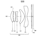
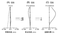
- FIG. 10 is an aberration diagram of Example 6.
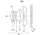
- FIG. 10 is an aberration diagram of Example 7.
- the schematic diagram which shows the schematic structural example of the digital apparatus carrying an imaging lens.
- the imaging lens and the like according to the present invention will be described below.
- the first type of imaging lens is an imaging lens for forming a subject image on an imaging surface of the imaging device (for example, a photoelectric conversion unit of a solid-state imaging device), and is a positive first lens in order from the object side.
- f1 focal length of the first lens
- f2 focal length of the second lens
- the basic configuration of the first type includes a positive first lens, an aperture stop, a positive second lens, and a negative third lens. And a positive fourth lens and a negative fifth lens.
- a positive lens group including a first lens, an aperture stop, a second lens, a third lens, and a fourth lens, and a negative fifth lens are arranged in a so-called telephoto type arrangement. Therefore, this configuration is advantageous for reducing the overall length of the imaging lens.
- Conditional expression (1) optimizes the power arrangement before and after the aperture by setting the focal length of the first lens and the second lens to an appropriate range (power: an amount defined by the reciprocal of the focal length), and the total length Is a conditional expression for appropriately achieving the shortening of the lens and the correction of aberration.
- conditional expression (1) it is possible to prevent the focal length of the first lens from becoming too long relative to the focal length of the second lens, and to maintain symmetry before and after the aperture. It is possible to prevent the field curvature from being excessively overturned and the distortion aberration from being greatly plus (cushion type). Furthermore, shortening of the overall lens length can be achieved.
- the second type of imaging lens is an imaging lens for forming a subject image on an imaging surface of the imaging element (for example, a photoelectric conversion unit of a solid-state imaging element), and is a positive first lens in order from the object side.
- a positive second lens, a negative third lens, a positive fourth lens, and a negative fifth lens which satisfy the following conditional expression (2).
- f3 focal length of the third lens
- f focal length of the entire imaging lens system, It is.
- the optical element having power is five lenses.
- the second type basic configuration includes a positive first lens, a positive second lens, a negative third lens, and a positive lens. It consists of a fourth lens and a negative fifth lens.
- a positive lens group including a first lens, a second lens, a third lens, and a fourth lens and a negative fifth lens are in a so-called telephoto type arrangement. Therefore, this configuration is advantageous for reducing the overall length of the imaging lens.
- Conditional expression (2) is a conditional expression for achieving shortening of the entire length of the imaging lens and good aberration correction by setting the focal length of the third lens in an appropriate range. If the upper limit of conditional expression (2) is exceeded, the negative power of the third lens becomes too strong, making it difficult to shorten the entire length of the imaging lens. Further, higher-order spherical aberration and coma aberration are generated in the third lens. If the lower limit of conditional expression (2) is not reached, the negative power of the third lens becomes too weak, making it difficult to correct the Petzval sum, and the imaging performance at the periphery of the screen will deteriorate.
- a third type configuration that has all the first and second type characteristic configurations. That is, from the viewpoint described above, in order from the object side, the positive first lens, the aperture stop, the positive second lens, the negative third lens, the positive fourth lens, and the negative fifth lens. It is desirable that the conditional expressions (1) and (2) are satisfied.
- a bright five-lens imaging lens of about F2.0 which is smaller than the conventional type and has various aberrations corrected well, and the It is possible to realize the provided imaging optical device. If the imaging optical device is used in a digital device such as a mobile phone or a portable information terminal, it is possible to add a high-performance image input function to the digital device in a compact manner. It can contribute to functionalization. The conditions for achieving such effects in a well-balanced manner and achieving higher optical performance, downsizing, etc. will be described below.
- conditional expression (1a) defines a more preferable condition range based on the above viewpoints, etc., among the condition ranges defined by the conditional expression (1). Therefore, the above effect can be further enhanced preferably by satisfying conditional expression (1a).
- conditional expression (2a) defines a more preferable condition range based on the above viewpoints, etc., among the condition ranges defined by the conditional expression (2). Therefore, the above effect can be further increased preferably by satisfying conditional expression (2a).
- the first lens has a convex surface facing the object side and the second lens has a convex surface facing the image side.
- the third lens has a concave surface facing the image side.
- the image side surface of the third lens concave, it is possible to easily correct lateral chromatic aberration and Petzval sum.
- Conditional expression (3) is a conditional expression for shortening the entire length of the imaging lens and achieving appropriate aberration correction by setting the focal length of the second lens in an appropriate range.
- conditional expression (3) By falling below the upper limit of conditional expression (3), it is possible to prevent the positive power of the second lens from becoming too small, and the composite principal point of the first lens to the fourth lens can be arranged closer to the object side. Shortening of the overall length of the imaging lens can be achieved.
- exceeding the lower limit of the conditional expression (3) can suppress higher-order spherical aberration and coma generated in the second lens.
- conditional expression (3a) 1.5 ⁇ f2 / f ⁇ 6.0 (3a)
- This conditional expression (3a) defines a more preferable condition range based on the above viewpoints, etc., among the condition ranges defined by the conditional expression (3). Therefore, the above effect can be further increased preferably by satisfying conditional expression (3a).
- Conditional expression (4) is a conditional expression for achieving shortening of the entire length of the imaging lens and appropriate aberration correction by setting the focal length of the first lens in an appropriate range.
- the positive power of the first lens can be prevented from becoming too small, and the composite principal point of the first lens to the fourth lens can be arranged closer to the object side. Shortening of the overall length of the imaging lens can be achieved.
- the lower limit of the conditional expression (4) higher-order spherical aberration and coma generated in the first lens can be suppressed.
- conditional expression (4a) defines a more preferable condition range based on the above viewpoints, etc., among the condition ranges defined by the conditional expression (4). Therefore, the above effect can be further increased preferably by satisfying conditional expression (4a).
- Conditional expression (5) is a conditional expression for appropriately correcting axial chromatic aberration and lateral chromatic aberration by setting the dispersion of the third lens in an appropriate range.
- the lower limit of conditional expression (5) is not reached, the longitudinal chromatic aberration can be sufficiently corrected, but the lateral chromatic aberration generated by the peripheral luminous flux becomes large and difficult to correct.
- the upper limit of conditional expression (5) is exceeded, the lateral chromatic aberration of the peripheral light beam can be suppressed, but the axial chromatic aberration cannot be corrected.
- conditional expression (5a) defines a more preferable condition range based on the above viewpoints, etc., among the condition ranges defined by the conditional expression (5). Therefore, the above effect can be further increased preferably by satisfying conditional expression (5a).
- the image side surface of the fifth lens has an aspherical shape, has a negative refractive power at the center thereof, becomes weaker toward the periphery, has an inflection point, and has the following conditional expression (6 ) Is desirable.
- f focal length of the entire imaging lens system
- T5 thickness of the fifth lens on the optical axis, It is.
- the negative refracting power becomes weaker as the image side surface of the fifth lens goes from the optical axis to the periphery, and the telecentric characteristic of the image side light beam can be easily secured by making the aspherical shape having an inflection point. Further, the image side surface of the fourth lens does not need to excessively weaken the negative refractive power at the periphery of the lens, and the off-axis aberration can be corrected well.
- the “inflection point” is a point on the aspheric surface where the tangent plane of the aspherical vertex is a plane perpendicular to the optical axis in the curve of the lens cross-sectional shape within the effective radius.
- Conditional expression (6) is a conditional expression for appropriately achieving the image plane of the imaging lens by setting the axial thickness of the fifth lens in an appropriate range.
- the refractive power in the vicinity of the optical axis and the refractive power in the vicinity of the fifth lens are greatly different from those of the other lenses, so that the influence of the axial thickness on the field curvature is large.
- By falling below the upper limit of conditional expression (6) it is possible to prevent the field curvature from falling to the over side.
- by exceeding the lower limit of conditional expression (6) it is possible to prevent the field curvature from falling to the under side. Therefore, by satisfying conditional expression (6), it is possible to prevent the image plane property of the imaging lens from falling too much toward the over side or the under side.
- conditional expression (6a) defines a more preferable condition range based on the above viewpoints, etc., among the condition ranges defined by the conditional expression (6). Therefore, the above effect can be further enhanced preferably by satisfying conditional expression (6a).
- the imaging lens has only a plastic lens as a lens.
- a solid-state imaging device having the same number of pixels has been developed with a small pixel pitch and consequently a small imaging surface size.
- all lenses are made of plastic lenses manufactured by injection molding, so that even lenses with small radii of curvature and outer diameters are inexpensive. Mass production is possible.
- the plastic lens can lower the press temperature, it is possible to suppress the wear of the molding die, and as a result, the number of replacements and maintenance times of the molding die can be reduced, and the cost can be reduced.
- the imaging lens according to the present invention is suitable for use as an imaging lens for a digital device with an image input function (for example, a portable terminal). By combining this with an imaging device or the like, an image of a subject is optically captured.
- An imaging optical device that outputs an electrical signal can be configured.
- the imaging optical device is an optical device that constitutes a main component of a camera used for still image shooting and moving image shooting of a subject, for example, an imaging lens that forms an optical image of an object in order from the object (that is, subject) side, And an imaging device that converts an optical image formed by the imaging lens into an electrical signal.
- the imaging lens having the above-described characteristic configuration is arranged so that an optical image of the subject is formed on the light receiving surface (that is, the imaging surface) of the imaging device, and thus has high performance at a small size, low cost.
- An imaging optical device and a digital device including the imaging optical device can be realized.
- Examples of digital devices with an image input function include cameras such as digital cameras, video cameras, surveillance cameras, in-vehicle cameras, videophone cameras, etc., and personal computers, mobile terminals (for example, mobile phones, mobile computers, etc.) Small and portable information device terminals), peripheral devices (scanners, printers, etc.), cameras incorporated in or external to other digital devices, and the like.
- cameras such as digital cameras, video cameras, surveillance cameras, in-vehicle cameras, videophone cameras, etc.
- mobile terminals for example, mobile phones, mobile computers, etc.
- Small and portable information device terminals for example, mobile phones, mobile computers, etc.
- peripheral devices scanners, printers, etc.
- cameras incorporated in or external to other digital devices and the like.
- a digital device with an image input function such as a mobile phone with a camera can be configured.
- FIG. 15 is a schematic cross-sectional view showing a schematic configuration example of a digital device DU as an example of a digital device with an image input function.
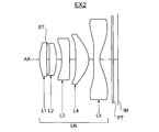
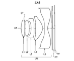
- the imaging optical device LU mounted in the digital device DU shown in FIG. 15 includes an imaging lens LN (AX: optical axis) that forms an optical image (image plane) IM of an object in order from the object (that is, subject) side, A parallel plate PT (cover glass of the image sensor SR; corresponding to an optical filter such as an optical low-pass filter and an infrared cut filter disposed as necessary) and a light receiving surface (imaging surface) SS by the imaging lens LN. And an imaging element SR that converts the optical image IM formed thereon into an electrical signal.
- AX optical axis
- the image pickup optical device LU When a digital device DU with an image input function is configured with this image pickup optical device LU, the image pickup optical device LU is usually arranged inside the body, but when necessary to realize the camera function, a form as necessary is adopted. Is possible.
- the unitized imaging optical device LU can be configured to be detachable or rotatable with respect to the main body of the digital device DU.
- the imaging lens LN has a single-focus five-lens configuration including the first to fifth lenses L1 to L5 in order from the object side, and forms the optical image IM on the light receiving surface SS of the imaging element SR. It has become.
- the image sensor SR for example, a solid-state image sensor such as a CCD image sensor or a CMOS image sensor having a plurality of pixels is used. Since the imaging lens LN is provided so that the optical image IM of the subject is formed on the light receiving surface SS which is a photoelectric conversion unit of the imaging element SR, the optical image IM formed by the imaging lens LN is the imaging element. It is converted into an electric signal by SR.
- the digital device DU includes a signal processing unit 1, a control unit 2, a memory 3, an operation unit 4, a display unit 5 and the like in addition to the imaging optical device LU.
- the signal generated by the image sensor SR is subjected to predetermined digital image processing, image compression processing, and the like as required by the signal processing unit 1 and recorded as a digital video signal in the memory 3 (semiconductor memory, optical disk, etc.) In some cases, it is transmitted to other devices via a cable or converted into an infrared signal or the like (for example, a communication function of a mobile phone).
- the control unit 2 is composed of a microcomputer, and controls functions such as a photographing function (still image photographing function, moving image photographing function, etc.), an image reproduction function, etc .; and a lens moving mechanism for focusing, etc.
- the control unit 2 controls the imaging optical device LU so as to perform at least one of still image shooting and moving image shooting of a subject.
- the display unit 5 includes a display such as a liquid crystal monitor, and displays an image using an image signal converted by the image sensor SR or image information recorded in the memory 3.
- the operation unit 4 is a part including operation members such as an operation button (for example, a release button) and an operation dial (for example, a shooting mode dial), and transmits information input by the operator to the control unit 2.
- FIGS. 1, 3, 5, 7, 9, 11, and 13 show first to seventh embodiments of the imaging lens LN in an infinite focus state in optical cross sections.
- the j-th lens Lj is a lens located at the j-th from the object side, and the parallel plate PT disposed on the image side of the imaging lens LN includes an optical low-pass filter, an IR cut filter, a seal glass of a solid-state imaging device, and the like. It is assumed. All the lens surfaces constituting the imaging lens LN are aspheric surfaces, and all the lenses are assumed to be made of a plastic material as an optical material. In addition, it is assumed that the entire focus is performed by moving the first lens L1 to the fifth lens L5 as a single unit for the focus position adjustment in the auto focus, the macro switching function, or the like.
- the imaging lenses LN of the first to seventh embodiments from the object side, the positive first lens L1, the aperture stop ST, the positive second lens L2, the negative third lens L3, and the positive fourth lens L4. And the negative fifth lens L5 in this order.
- the first lens L1 has a convex surface facing the object side
- the second lens L2 has a convex surface facing the image side
- the third lens L3 has a concave surface facing the image side.
- the image side surface of the fifth lens is an aspheric surface having an inflection point at a position other than the intersection with the optical axis AX.
- the plastic material has a large refractive index change at the time of temperature change, so if all lenses are made of plastic lenses, the image point position of the entire imaging lens system will fluctuate when the ambient temperature changes. It will be held. Recently, however, it has been found that mixing inorganic fine particles in a plastic material can reduce the effect of temperature changes on the plastic material. More specifically, mixing fine particles with a transparent plastic material generally causes scattering of light and lowers the transmittance, making it difficult to use as an optical material. If the wavelength is smaller than this wavelength, scattering can be substantially prevented from occurring.
- the refractive index of the plastic material decreases as the temperature increases, but the refractive index of the inorganic particles increases as the temperature increases. Therefore, it is possible to make almost no change in the refractive index by using these temperature dependencies so as to cancel each other.
- a plastic material with extremely low temperature dependency of the refractive index can be obtained.
- niobium oxide (Nb 2 O 5 ) in an acrylic resin a change in refractive index due to a temperature change can be reduced.
- such a positive lens having a relatively large refractive power for example, the first lens L1 and the fourth lens L4 or all the lenses (the first to fifth lenses L1 to L5) can be used in this way.
- a plastic material in which various inorganic particles are dispersed it is possible to suppress the image point position fluctuation at the time of temperature change of the entire imaging lens LN system.
- the principal ray incident angle of the light beam incident on the imaging surface of the solid-state imaging device is not necessarily designed to be sufficiently small in the periphery of the imaging surface.
- shading can be reduced by reviewing the arrangement of the color filters of the solid-state imaging device and the on-chip microlens array. Specifically, if the pitch of the arrangement of the color filters and the on-chip microlens array is set slightly smaller than the pixel pitch of the image pickup surface of the image pickup device, the color filter for each pixel becomes closer to the periphery of the image pickup surface.
- the on-chip microlens array is shifted to the optical axis side of the imaging lens, the obliquely incident light beam can be efficiently guided to the light receiving portion of each pixel. Thereby, the shading which generate
- a design example aiming at further miniaturization is provided for the portion in which the requirement is relaxed.
- Examples 1 to 7 (EX1 to EX7) listed here are numerical examples corresponding to the first to seventh embodiments, respectively, and are optical configuration diagrams showing the first to seventh embodiments. (FIGS. 1, 3, 5, 7, 9, 11, and 13) show the lens configurations of the corresponding Examples 1 to 7, respectively.
- the maximum image height), the total lens length (TL, mm), and the half angle of view ( ⁇ , °) are shown, and the focal length (mm) of each lens is shown as single lens data.
- the back focus fB used here is the distance from the image side surface of the parallel plate PT to the image plane IM
- the total lens length TL is the distance from the front lens surface to the image plane IM.
- Table 1 shows values corresponding to the conditional expressions of the respective examples.
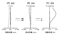
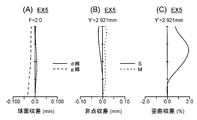
- 2, 4, 6, 8, 10, 12, and 14 are aberration diagrams of Examples 1 to 7 (EX 1 to 7), where (A) is spherical aberration (mm), (B ) Shows astigmatism (mm), and (C) shows distortion (%).
- the solid line shows the spherical aberration amount for the d-line (wavelength 587.56 nm)
- the broken line shows the spherical aberration amount for the g-line (wavelength 435.84 nm)
- the vertical axis represents the F value.
- the broken line M represents the meridional image plane with respect to the d-line
- the solid line S represents the sagittal image plane with respect to the d-line by the amount of deviation in the optical axis AX direction from the paraxial image plane.
- the axis represents the image height Y ′ (mm).
- the horizontal axis represents the distortion with respect to the d-line
- the vertical axis represents the image height Y ′ (mm). Note that the maximum image height Y ′ corresponds to half the diagonal length of the imaging surface SS of the imaging element SR.
- the imaging lens LN (FIG. 1) of Example 1 includes, in order from the object side, a positive first lens L1, a positive second lens L2, a negative third lens L3, and a positive fourth lens L4.
- the negative fifth lens L5 is composed of an aspherical lens surface, and an aperture stop ST is disposed between the first lens L1 and the second lens L2.
- the first lens L1 is a positive meniscus lens convex toward the object side
- the second lens L2 is a positive meniscus lens convex toward the image side
- the third lens L3 is
- the fourth lens L4 is a positive meniscus lens convex to the image side
- the fifth lens L5 is a negative meniscus lens concave to the image side.
- the imaging lens LN (FIG. 3) of Example 2 includes, in order from the object side, a positive first lens L1, a positive second lens L2, a negative third lens L3, and a positive fourth lens L4.
- the negative fifth lens L5 is composed of an aspherical lens surface, and an aperture stop ST is disposed between the first lens L1 and the second lens L2.
- the first lens L1 is a positive meniscus lens convex on the object side
- the second lens L2 is a biconvex positive lens
- the third lens L3 is biconcave.
- the fourth lens L4 is a negative meniscus lens convex to the image side
- the fifth lens L5 is a negative meniscus lens concave to the image side.
- the imaging lens LN (FIG. 5) of Example 3 includes, in order from the object side, a positive first lens L1, a positive second lens L2, a negative third lens L3, and a positive fourth lens L4.
- the negative fifth lens L5 is composed of an aspherical lens surface, and an aperture stop ST is disposed between the first lens L1 and the second lens L2.
- the first lens L1 is a positive meniscus lens convex on the object side
- the second lens L2 is a biconvex positive lens
- the third lens L3 is biconcave.
- the fourth lens L4 is a negative meniscus lens convex to the image side
- the fifth lens L5 is a negative meniscus lens concave to the image side.
- the imaging lens LN (FIG. 7) of Example 4 includes, in order from the object side, a positive first lens L1, a positive second lens L2, a negative third lens L3, a positive fourth lens L4,
- the negative fifth lens L5 is composed of an aspherical lens surface, and an aperture stop ST is disposed between the first lens L1 and the second lens L2.
- the first lens L1 is a positive meniscus lens convex toward the object side
- the second lens L2 is a positive meniscus lens convex toward the image side
- the third lens L3 is
- the fourth lens L4 is a positive meniscus lens convex to the image side
- the fifth lens L5 is a negative meniscus lens concave to the image side.
- the imaging lens LN (FIG. 9) of Example 5 includes, in order from the object side, a positive first lens L1, a positive second lens L2, a negative third lens L3, a positive fourth lens L4,
- the negative fifth lens L5 is composed of an aspherical lens surface, and an aperture stop ST is disposed between the first lens L1 and the second lens L2.
- the first lens L1 is a positive meniscus lens convex toward the object side
- the second lens L2 is a positive meniscus lens convex toward the image side
- the third lens L3 is
- the fourth lens L4 is a positive meniscus lens convex to the image side
- the fifth lens L5 is a negative meniscus lens concave to the image side.
- the imaging lens LN (FIG. 11) of Example 6 includes, in order from the object side, a positive first lens L1, a positive second lens L2, a negative third lens L3, and a positive fourth lens L4.
- the negative fifth lens L5 is composed of an aspherical lens surface, and an aperture stop ST is disposed between the first lens L1 and the second lens L2.
- the first lens L1 is a positive meniscus lens convex on the object side
- the second lens L2 is a biconvex positive lens
- the third lens L3 is on the image side.
- the fourth lens L4 is a positive meniscus lens convex to the image side
- the fifth lens L5 is a negative meniscus lens concave to the image side.
- the imaging lens LN (FIG. 13) of Example 7 includes, in order from the object side, a positive first lens L1, a positive second lens L2, a negative third lens L3, and a positive fourth lens L4.
- the negative fifth lens L5 is composed of an aspherical lens surface, and an aperture stop ST is disposed between the first lens L1 and the second lens L2.
- the first lens L1 is a positive meniscus lens convex on the object side
- the second lens L2 is a biconvex positive lens
- the third lens L3 is on the image side.
- the fourth lens L4 is a positive meniscus lens convex to the image side
- the fifth lens L5 is a negative meniscus lens concave to the image side.
Abstract
撮像レンズは、物体側より順に、正の第1レンズと、開口絞りと、正の第2レンズと、負の第3レンズと、正の第4レンズと、負の第5レンズと、から成り、条件式:0<f1/f2<1.26(f1:第1レンズの焦点距離、f2:第2レンズの焦点距離)を満足し、撮像素子の撮像面に被写体像を結像させる。
Description
本発明は、撮像レンズに関するものである。更に詳しくは、被写体の映像を撮像素子(例えば、CCD(Charge Coupled Device)型イメージセンサ,CMOS(Complementary Metal-Oxide Semiconductor)型イメージセンサ等の固体撮像素子)で取り込む撮像光学装置と、それを搭載した画像入力機能付きデジタル機器と、撮像素子の受光面上に被写体の光学像を形成する小型の撮像レンズと、に関するものである。
近年、CCD型イメージセンサやCMOS型イメージセンサ等の固体撮像素子を用いた撮像光学装置が携帯端末に搭載されるようになり、その携帯端末の普及の増大に伴って、より高画質の画像が得られるよう、高画素数を持つ撮像素子を使用した撮像光学装置の搭載されたものが市場に供給されるようになってきている。その高画素数を持つ撮像素子は大型化を伴っていたが、近年、画素の高細化が進み、撮像素子は小型化されるようになってきている。このような高細化された撮像素子に使用される撮像レンズには、高細化された画素に対応するために高い解像力が要求される。
レンズの解像力はF値により限界があり、F値の小さい明るいレンズの方が高解像力を得ることができるため、従来のようにF2.8程度のF値では十分な性能が得られなくなってきている。そこで、高画素化・高細化・小型化された撮像素子に適した、F2程度の明るい撮像レンズが求められるようになってきた。このような用途の撮像レンズとして、3枚構成又は4枚構成のレンズに比べ大口径比化及び高性能化が可能であるという理由から、5枚構成の撮像レンズが提案されている。
この5枚構成の撮像レンズとしては、物体側より順に、前群,開口絞り及び後群から成り、前群が正又は負の屈折力を有する第1レンズと正の屈折力を有する第2レンズとで構成され、後群が負の屈折力を有する第3レンズと正の屈折力を有する第4レンズと負又は正の屈折力を有する第5レンズとで構成された撮像レンズが、特許文献1及び特許文献2に開示されている。また、4枚構成の撮像レンズとしては、物体側より順に、前群,開口絞り及び後群から成り、前群が負の屈折力を有する第1レンズと正の屈折力を有する第2レンズとで構成され、後群が負の屈折力を有する第3レンズと正の屈折力を有する第4レンズとで構成された撮像レンズが、特許文献3に開示されている。
しかしながら、上記特許文献1に記載の撮像レンズは、前群が球面系で構成されているためF2程度に明るくすると、球面収差やコマ収差の補正が不十分となり、良好な性能を確保できなくなる。また、前群及び後群とも正の屈折力を有する構成であるため、後群が負の屈折力を有するテレフォトタイプのような構成に比べ、光学系の主点位置が像側になりバックフォーカスが長くなる。このため、小型化には不利なタイプである。
また、上記特許文献2に記載の撮像レンズは、F2程度の明るさを有しているが、開口絞りの物体側に配置される第1レンズ及び第2レンズともに正の屈折力を有する構成であるため、前群での色補正が不十分である。さらに、特許文献1に記載のものとと同様に、前群及び後群とも正の屈折力を有する構成であるとともに、最終レンズも正レンズであるため、小型化には不利なタイプである。
さらに、上記特許文献3に記載の撮像レンズは、F2程度の明るさを有しているが、4枚構成であるため収差補正が不十分である。したがって、高画素化に適した撮像レンズとは言いがたい。
本発明はこのような問題点に鑑みてなされたものであって、その目的は、従来タイプより小型でありながらも諸収差が良好に補正された、F2.0程度の明るい5枚構成の撮像レンズを提供することにある。
上記目的を達成するために、第1の発明の撮像レンズは、撮像素子の撮像面に被写体像を結像させるための撮像レンズであって、物体側より順に、正の第1レンズと、開口絞りと、正の第2レンズと、負の第3レンズと、正の第4レンズと、負の第5レンズと、から成り、以下の条件式(1)を満足することを特徴とする。
0<f1/f2<1.26 …(1)
ただし、
f1:第1レンズの焦点距離、
f2:第2レンズの焦点距離、
である。
0<f1/f2<1.26 …(1)
ただし、
f1:第1レンズの焦点距離、
f2:第2レンズの焦点距離、
である。
第2の発明の撮像レンズは、撮像素子の撮像面に被写体像を結像させるための撮像レンズであって、物体側より順に、正の第1レンズと、正の第2レンズと、負の第3レンズと、正の第4レンズと、負の第5レンズと、から成り、以下の条件式(2)を満足することを特徴とする。
-4.0<f3/f<-1.1 …(2)
ただし、
f3:第3レンズの焦点距離、
f:撮像レンズ全系の焦点距離、
である。
-4.0<f3/f<-1.1 …(2)
ただし、
f3:第3レンズの焦点距離、
f:撮像レンズ全系の焦点距離、
である。
第3の発明の撮像レンズは、撮像素子の撮像面に被写体像を結像させるための撮像レンズであって、物体側より順に、正の第1レンズと、開口絞りと、正の第2レンズと、負の第3レンズと、正の第4レンズと、負の第5レンズと、から成り、以下の条件式(1)及び(2)を満足することを特徴とする。
0<f1/f2<1.26 …(1)
-4.0<f3/f<-1.1 …(2)
ただし、
f1:第1レンズの焦点距離、
f2:第2レンズの焦点距離、
f3:第3レンズの焦点距離、
f:撮像レンズ全系の焦点距離、
である。
0<f1/f2<1.26 …(1)
-4.0<f3/f<-1.1 …(2)
ただし、
f1:第1レンズの焦点距離、
f2:第2レンズの焦点距離、
f3:第3レンズの焦点距離、
f:撮像レンズ全系の焦点距離、
である。
第4の発明の撮像レンズは、上記第1~第3のいずれか1つの発明において、前記第1レンズが物体側に凸面を向けており、前記第2レンズが像側に凸面を向けていることを特徴とする。
第5の発明の撮像レンズは、上記第1~第4のいずれか1つの発明において、前記第3レンズが像側に凹面を向けていることを特徴とする。
第6の発明の撮像レンズは、上記第1~第5のいずれか1つの発明において、以下の条件式(3)を満足することを特徴とする。
1.41<f2/f<10.0 …(3)
ただし、
f2:第2レンズの焦点距離、
f:撮像レンズ全系の焦点距離、
である。
1.41<f2/f<10.0 …(3)
ただし、
f2:第2レンズの焦点距離、
f:撮像レンズ全系の焦点距離、
である。
第7の発明の撮像レンズは、上記第1~第6のいずれか1つの発明において、以下の条件式(4)を満足することを特徴とする。
1.0<f1/f<3.0 …(4)
ただし、
f1:第1レンズの焦点距離、
f:撮像レンズ全系の焦点距離、
である。
1.0<f1/f<3.0 …(4)
ただし、
f1:第1レンズの焦点距離、
f:撮像レンズ全系の焦点距離、
である。
第8の発明の撮像レンズは、上記第1~第7のいずれか1つの発明において、以下の条件式(5)を満足することを特徴とする。
15<νd3<31 …(5)
ただし、
νd3:第3レンズのd線に対するアッベ数、
である。
15<νd3<31 …(5)
ただし、
νd3:第3レンズのd線に対するアッベ数、
である。
第9の発明の撮像レンズは、上記第1~第8のいずれか1つの発明において、前記第5レンズの像側面が非球面形状を有し、その中心では負の屈折力を持ち、周辺に向かうに従い負の屈折力が弱くなり、変曲点を有し、以下の条件式(6)を満足することを特徴とする。
0.05<T5/f<0.2 …(6)
ただし、
f:撮像レンズ全系の焦点距離、
T5:第5レンズの光軸上の厚み、
である。
0.05<T5/f<0.2 …(6)
ただし、
f:撮像レンズ全系の焦点距離、
T5:第5レンズの光軸上の厚み、
である。
第10の発明の撮像レンズは、上記第1~第9のいずれか1つの発明において、レンズが全てプラスチック材料で形成されていることを特徴とする。
第11の発明の撮像光学装置は、上記第1~第10のいずれか1つの発明に係る撮像レンズと、撮像面上に形成された光学像を電気的な信号に変換する撮像素子と、を備え、前記撮像素子の撮像面上に被写体の光学像が形成されるように前記撮像レンズが設けられていることを特徴とする。
第12の発明のデジタル機器は、上記第11の発明に係る撮像光学装置を備えることにより、被写体の静止画撮影,動画撮影のうちの少なくとも一方の機能が付加されたことを特徴とする。
第13の発明のデジタル機器は、上記第12の発明において、携帯端末であることを特徴とする。
本発明の構成を採用することにより、従来タイプより小型でありながらも諸収差が良好に補正された、F2.0程度の明るい5枚構成の撮像レンズと、それを備えた撮像光学装置を実現することができる。そして、本発明に係る撮像光学装置を携帯電話,携帯情報端末等のデジタル機器に用いることによって、デジタル機器に対し高性能の画像入力機能をコンパクトに付加することが可能となる。
以下、本発明に係る撮像レンズ等を説明する。第1のタイプの撮像レンズは、撮像素子の撮像面(例えば、固体撮像素子の光電変換部)に被写体像を結像させるための撮像レンズであって、物体側より順に、正の第1レンズと、開口絞りと、正の第2レンズと、負の第3レンズと、正の第4レンズと、負の第5レンズと、から成り、以下の条件式(1)を満足することを特徴としている。
0<f1/f2<1.26 …(1)
ただし、
f1:第1レンズの焦点距離、
f2:第2レンズの焦点距離、
である。
0<f1/f2<1.26 …(1)
ただし、
f1:第1レンズの焦点距離、
f2:第2レンズの焦点距離、
である。
小型で明るく更に収差の良好に補正された撮像レンズを得るために、第1のタイプの基本構成は、正の第1レンズと、開口絞りと、正の第2レンズと、負の第3レンズと、正の第4レンズと、負の第5レンズと、から成っている。このレンズ構成は、物体側より順に、第1レンズ,開口絞り,第2レンズ,第3レンズ及び第4レンズから成る正レンズ群と、負の第5レンズとで、いわゆるテレフォトタイプの配置になっているため、撮像レンズ全長の小型化には有利な構成である。さらに、5枚構成のうち2枚を負レンズとすることで、発散作用を有する面を多くしてペッツバール和の補正を容易とし、画面周辺部まで良好な結像性能を確保した撮像レンズを得ることが可能となる。また、開口絞りを第1レンズと第2レンズとの間に配置することで、像側光束のテレセントリック性を確保することが可能となり、倍率色収差及び歪曲収差の発生を抑制することが可能となる。
条件式(1)は、第1レンズと第2レンズの焦点距離を適切な範囲に設定することにより、絞り前後のパワー配置を最適化し(パワー:焦点距離の逆数で定義される量)、全長の短縮化と収差補正を適切に達成するための条件式である。条件式(1)の下限を上回ることで、第1レンズの焦点距離が第2レンズの焦点距離に対して相対的に短くなりすぎるのを防ぎ、絞り前後の対称性を保つことで、像面湾曲がアンダーに大きく倒れたり、歪曲収差が大きくマイナス(樽型)になったりするのを防ぐことができる。一方、条件式(1)の上限を下回ることで、第1レンズの焦点距離が第2レンズの焦点距離に対して相対的に長くなりすぎるのを防ぎ、絞り前後の対称性を保つことで、像面湾曲が大きくオーバーに倒れたり、歪曲収差が大きくプラス(糸巻き型)になったりするのを防ぐことができる。さらに、レンズ全長の短縮化も達成可能となる。
第2のタイプの撮像レンズは、撮像素子の撮像面(例えば、固体撮像素子の光電変換部)に被写体像を結像させるための撮像レンズであって、物体側より順に、正の第1レンズと、正の第2レンズと、負の第3レンズと、正の第4レンズと、負の第5レンズと、から成り、以下の条件式(2)を満足することを特徴としている。
-4.0<f3/f<-1.1 …(2)
ただし、
f3:第3レンズの焦点距離、
f:撮像レンズ全系の焦点距離、
である。
-4.0<f3/f<-1.1 …(2)
ただし、
f3:第3レンズの焦点距離、
f:撮像レンズ全系の焦点距離、
である。
この撮像レンズにおいて、パワーを有する光学素子は5枚のレンズである。小型で明るく更に収差の良好に補正された撮像レンズを得るために、第2のタイプの基本構成は、正の第1レンズと、正の第2レンズと、負の第3レンズと、正の第4レンズと、負の第5レンズと、から成っている。このレンズ構成は、物体側より順に、第1レンズ,第2レンズ,第3レンズ及び第4レンズから成る正レンズ群と、負の第5レンズとで、いわゆるテレフォトタイプの配置になっているため、撮像レンズ全長の小型化には有利な構成である。さらに、5枚構成のうち2枚を負レンズとすることで、発散作用を有する面を多くしてペッツバール和の補正を容易とし、画面周辺部まで良好な結像性能を確保した撮像レンズを得ることが可能となる。
条件式(2)は、第3レンズの焦点距離を適切な範囲に設定することにより、撮像レンズ全長の短縮化と良好な収差補正とを達成するための条件式である。条件式(2)の上限を上回ると、第3レンズの負のパワーが強くなりすぎて、撮像レンズ全長を短縮化するのが困難になる。また、第3レンズで高次の球面収差やコマ収差が発生してしまう。条件式(2)の下限を下回ると、第3レンズの負のパワーが弱くなりすぎて、ペッツバール和の補正が困難となり、画面周辺部での結像性能が劣化してしまう。
上記第1,第2のタイプの特徴的構成をすべて有する第3のタイプの構成を採用することが好ましい。つまり、前述した観点からすると、物体側より順に、正の第1レンズと、開口絞りと、正の第2レンズと、負の第3レンズと、正の第4レンズと、負の第5レンズと、から成り、前記条件式(1)及び(2)を満足することが望ましい。
上記第1,第2又は第3のタイプの特徴的構成によると、従来タイプより小型でありながらも諸収差が良好に補正された、F2.0程度の明るい5枚構成の撮像レンズ及びそれを備えた撮像光学装置を実現することが可能である。そして、その撮像光学装置を携帯電話,携帯情報端末等のデジタル機器に用いれば、デジタル機器に対し高性能の画像入力機能をコンパクトに付加することが可能となり、そのコンパクト化,高性能化,高機能化等に寄与することができる。こういった効果をバランス良く得るとともに、更に高い光学性能,小型化等を達成するための条件等を以下に説明する。
以下の条件式(1a)を満足することが更に望ましい。
0.3<f1/f2<1.1 …(1a)
この条件式(1a)は、前記条件式(1)が規定している条件範囲のなかでも、前記観点等に基づいた更に好ましい条件範囲を規定している。したがって、好ましくは条件式(1a)を満たすことにより、上記効果をより一層大きくすることができる。
0.3<f1/f2<1.1 …(1a)
この条件式(1a)は、前記条件式(1)が規定している条件範囲のなかでも、前記観点等に基づいた更に好ましい条件範囲を規定している。したがって、好ましくは条件式(1a)を満たすことにより、上記効果をより一層大きくすることができる。
以下の条件式(2a)を満足することが更に望ましい。
-3.0<f3/f<-1.3 …(2a)
この条件式(2a)は、前記条件式(2)が規定している条件範囲のなかでも、前記観点等に基づいた更に好ましい条件範囲を規定している。したがって、好ましくは条件式(2a)を満たすことにより、上記効果をより一層大きくすることができる。
-3.0<f3/f<-1.3 …(2a)
この条件式(2a)は、前記条件式(2)が規定している条件範囲のなかでも、前記観点等に基づいた更に好ましい条件範囲を規定している。したがって、好ましくは条件式(2a)を満たすことにより、上記効果をより一層大きくすることができる。
前記第1レンズが物体側に凸面を向けており、前記第2レンズが像側に凸面を向けていることが望ましい。第1レンズの物体側面を凸形状、第2レンズの像側面を凸形状とすることで、絞り前後での対称性を確保することができ、倍率色収差や歪曲収差を適切に補正することが可能となる。
前記第3レンズが像側に凹面を向けていることが望ましい。第3レンズの像側面を凹面とすることで、倍率色収差やペッツバール和の補正を容易に行うことが可能となる。
以下の条件式(3)を満足することが望ましい。
1.41<f2/f<10.0 …(3)
ただし、
f2:第2レンズの焦点距離、
f:撮像レンズ全系の焦点距離、
である。
1.41<f2/f<10.0 …(3)
ただし、
f2:第2レンズの焦点距離、
f:撮像レンズ全系の焦点距離、
である。
条件式(3)は、第2レンズの焦点距離を適切な範囲に設定することにより、撮像レンズ全長の短縮化と適切な収差補正を達成するための条件式である。条件式(3)の上限を下回ることで、第2レンズの正パワーが小さくなりすぎるのを防ぐことができ、第1レンズから第4レンズの合成主点をより物体側に配置することができ、撮像レンズ全長の短縮化が達成できる。一方、条件式(3)の下限を上回ることで、第2レンズで発生する高次の球面収差やコマ収差を抑えることができる。
以下の条件式(3a)を満足することが更に望ましい。
1.5<f2/f<6.0 …(3a)
この条件式(3a)は、前記条件式(3)が規定している条件範囲のなかでも、前記観点等に基づいた更に好ましい条件範囲を規定している。したがって、好ましくは条件式(3a)を満たすことにより、上記効果をより一層大きくすることができる。
1.5<f2/f<6.0 …(3a)
この条件式(3a)は、前記条件式(3)が規定している条件範囲のなかでも、前記観点等に基づいた更に好ましい条件範囲を規定している。したがって、好ましくは条件式(3a)を満たすことにより、上記効果をより一層大きくすることができる。
以下の条件式(4)を満足することが望ましい。
1.0<f1/f<3.0 …(4)
ただし、
f1:第1レンズの焦点距離、
f:撮像レンズ全系の焦点距離、
である。
1.0<f1/f<3.0 …(4)
ただし、
f1:第1レンズの焦点距離、
f:撮像レンズ全系の焦点距離、
である。
条件式(4)は、第1レンズの焦点距離を適切な範囲に設定することにより、撮像レンズ全長の短縮化と適切な収差補正を達成するための条件式である。条件式(4)の上限を下回ることで、第1レンズの正パワーが小さくなりすぎるのを防ぐことができ、第1レンズから第4レンズの合成主点をより物体側に配置することができ、撮像レンズ全長の短縮化が達成できる。一方、条件式(4)の下限を上回ることで、第1レンズで発生する高次の球面収差やコマ収差を抑えることができる。
以下の条件式(4a)を満足することが更に望ましい。
1.2<f1/f<2.5 …(4a)
この条件式(4a)は、前記条件式(4)が規定している条件範囲のなかでも、前記観点等に基づいた更に好ましい条件範囲を規定している。したがって、好ましくは条件式(4a)を満たすことにより、上記効果をより一層大きくすることができる。
1.2<f1/f<2.5 …(4a)
この条件式(4a)は、前記条件式(4)が規定している条件範囲のなかでも、前記観点等に基づいた更に好ましい条件範囲を規定している。したがって、好ましくは条件式(4a)を満たすことにより、上記効果をより一層大きくすることができる。
以下の条件式(5)を満足することが望ましい。
15<νd3<31 …(5)
ただし、
νd3:第3レンズのd線に対するアッベ数、
である。
15<νd3<31 …(5)
ただし、
νd3:第3レンズのd線に対するアッベ数、
である。
条件式(5)は、第3レンズの分散を適切な範囲に設定することにより、軸上色収差と倍率色収差を適切に補正するための条件式である。条件式(5)の下限を下回った場合、軸上色収差は十分に補正可能であるが、周辺光束で発生する倍率色収差は大きくなって補正困難となる。一方、条件式(5)の上限を上回った場合、周辺光束の倍率色収差は抑えることが可能であるが、軸上色収差は補正しきれなくなる。
以下の条件式(5a)を満足することが更に望ましい。
17<νd3<27 …(5a)
この条件式(5a)は、前記条件式(5)が規定している条件範囲のなかでも、前記観点等に基づいた更に好ましい条件範囲を規定している。したがって、好ましくは条件式(5a)を満たすことにより、上記効果をより一層大きくすることができる。
17<νd3<27 …(5a)
この条件式(5a)は、前記条件式(5)が規定している条件範囲のなかでも、前記観点等に基づいた更に好ましい条件範囲を規定している。したがって、好ましくは条件式(5a)を満たすことにより、上記効果をより一層大きくすることができる。
前記第5レンズの像側面が非球面形状を有し、その中心では負の屈折力を持ち、周辺に向かうに従い負の屈折力が弱くなり、変曲点を有し、以下の条件式(6)を満足することが望ましい。
0.05<T5/f<0.2 …(6)
ただし、
f:撮像レンズ全系の焦点距離、
T5:第5レンズの光軸上の厚み、
である。
0.05<T5/f<0.2 …(6)
ただし、
f:撮像レンズ全系の焦点距離、
T5:第5レンズの光軸上の厚み、
である。
第5レンズの像側面を、光軸から周辺に行くに従って負の屈折力が弱くなり、また変曲点を有する非球面形状とすることで、像側光束のテレセントリック特性が確保しやすくなる。また、第4レンズの像側面は、レンズ周辺部で過度に負の屈折力を弱くする必要がなくなり、軸外収差を良好に補正することが可能となる。ここで「変曲点」とは、有効半径内でのレンズ断面形状の曲線において、非球面頂点の接平面が光軸と垂直な平面となるような非球面上の点のことである。
条件式(6)は、第5レンズの軸上厚みを適切な範囲に設定することにより、撮像レンズの像面性を適切に達成するための条件式である。第5レンズは、光軸付近での屈折力と周辺での屈折力とが他レンズと比べて大きく異なるため、軸上厚みの像面湾曲に対する影響が大きい。条件式(6)の上限を下回ることで、像面湾曲がオーバー側に倒れるのを防ぐことができる。一方、条件式(6)の下限を上回ることで、像面湾曲がアンダー側に倒れるのを防ぐことができる。したがって、条件式(6)を満たすことにより、撮像レンズの像面性がオーバー側やアンダー側に倒れすぎるのを防ぐことができる。
以下の条件式(6a)を満足することが更に望ましい。
0.07<T5/f<0.18 …(6a)
この条件式(6a)は、前記条件式(6)が規定している条件範囲のなかでも、前記観点等に基づいた更に好ましい条件範囲を規定している。したがって、好ましくは条件式(6a)を満たすことにより、上記効果をより一層大きくすることができる。
0.07<T5/f<0.18 …(6a)
この条件式(6a)は、前記条件式(6)が規定している条件範囲のなかでも、前記観点等に基づいた更に好ましい条件範囲を規定している。したがって、好ましくは条件式(6a)を満たすことにより、上記効果をより一層大きくすることができる。
レンズは全てプラスチック材料で形成されていることが望ましい。つまり、撮像レンズはレンズとしてプラスチックレンズのみを有することが望ましい。近年では、固体撮像素子を含む撮像光学装置全体の小型化を目的とし、同じ画素数の固体撮像素子であっても、画素ピッチが小さく、結果として撮像面サイズの小さいものが開発されている。このような撮像面サイズの小さい固体撮像素子向けの撮像レンズは、全系の焦点距離を比較的に短くする必要があるため、各レンズの曲率半径や外径がかなり小さくなってしまう。したがって、手間のかかる研磨加工により製造するガラスレンズと比較すれば、全てのレンズを、射出成形により製造されるプラスチックレンズで構成することにより、曲率半径や外径の小さなレンズであっても安価に大量生産が可能となる。また、プラスチックレンズはプレス温度を低くできることから、成形金型の損耗を抑えることができ、その結果、成形金型の交換回数やメンテナンス回数を減少させ、コスト低減を図ることができる。
本発明に係る撮像レンズは、画像入力機能付きデジタル機器(例えば携帯端末)用の撮像レンズとしての使用に適しており、これを撮像素子等と組み合わせることにより、被写体の映像を光学的に取り込んで電気的な信号として出力する撮像光学装置を構成することができる。撮像光学装置は、被写体の静止画撮影や動画撮影に用いられるカメラの主たる構成要素を成す光学装置であり、例えば、物体(すなわち被写体)側から順に、物体の光学像を形成する撮像レンズと、その撮像レンズにより形成された光学像を電気的な信号に変換する撮像素子と、を備えることにより構成される。そして、撮像素子の受光面(すなわち撮像面)上に被写体の光学像が形成されるように、前述した特徴的構成を有する撮像レンズが配置されることにより、小型・低コストで高い性能を有する撮像光学装置やそれを備えたデジタル機器を実現することができる。
画像入力機能付きデジタル機器の例としては、デジタルカメラ,ビデオカメラ,監視カメラ,車載カメラ,テレビ電話用カメラ等のカメラが挙げられ、また、パーソナルコンピュータ,携帯端末(例えば、携帯電話,モバイルコンピュータ等の小型で携帯可能な情報機器端末),これらの周辺機器(スキャナー,プリンター等),その他のデジタル機器等に内蔵又は外付けされるカメラが挙げられる。これらの例から分かるように、撮像光学装置を用いることによりカメラを構成することができるだけでなく、各種機器に撮像光学装置を搭載することによりカメラ機能を付加することが可能である。例えば、カメラ付き携帯電話等の画像入力機能付きデジタル機器を構成することが可能である。
図15に、画像入力機能付きデジタル機器の一例として、デジタル機器DUの概略構成例を模式的断面で示す。図15に示すデジタル機器DUに搭載されている撮像光学装置LUは、物体(すなわち被写体)側から順に、物体の光学像(像面)IMを形成する撮像レンズLN(AX:光軸)と、平行平板PT(撮像素子SRのカバーガラス;必要に応じて配置される光学的ローパスフィルタ,赤外カットフィルタ等の光学フィルタ等に相当する。)と、撮像レンズLNにより受光面(撮像面)SS上に形成された光学像IMを電気的な信号に変換する撮像素子SRと、を備えている。この撮像光学装置LUで画像入力機能付きデジタル機器DUを構成する場合、通常そのボディ内部に撮像光学装置LUを配置することになるが、カメラ機能を実現する際には必要に応じた形態を採用することが可能である。例えば、ユニット化した撮像光学装置LUをデジタル機器DUの本体に対して着脱自在又は回動自在に構成することが可能である。
撮像レンズLNは、前述したように、物体側より順に第1~第5レンズL1~L5から成る単焦点の5枚構成から成り、撮像素子SRの受光面SS上に光学像IMを形成する構成になっている。撮像素子SRとしては、例えば複数の画素を有するCCD型イメージセンサ,CMOS型イメージセンサ等の固体撮像素子が用いられる。撮像レンズLNは、撮像素子SRの光電変換部である受光面SS上に被写体の光学像IMが形成されるように設けられているので、撮像レンズLNによって形成された光学像IMは、撮像素子SRによって電気的な信号に変換される。
デジタル機器DUは、撮像光学装置LUの他に、信号処理部1,制御部2,メモリ3,操作部4,表示部5等を備えている。撮像素子SRで生成した信号は、信号処理部1で所定のデジタル画像処理や画像圧縮処理等が必要に応じて施され、デジタル映像信号としてメモリ3(半導体メモリ,光ディスク等)に記録されたり、場合によってはケーブルを介したり赤外線信号等に変換されたりして他の機器に伝送される(例えば携帯電話の通信機能)。制御部2はマイクロコンピュータから成っており、撮影機能(静止画撮影機能,動画撮影機能等),画像再生機能等の機能の制御;フォーカシングのためのレンズ移動機構の制御等を集中的に行う。例えば、被写体の静止画撮影,動画撮影のうちの少なくとも一方を行うように、制御部2により撮像光学装置LUに対する制御が行われる。表示部5は液晶モニター等のディスプレイを含む部分であり、撮像素子SRによって変換された画像信号あるいはメモリ3に記録されている画像情報を用いて画像表示を行う。操作部4は、操作ボタン(例えばレリーズボタン),操作ダイヤル(例えば撮影モードダイヤル)等の操作部材を含む部分であり、操作者が操作入力した情報を制御部2に伝達する。
次に、第1~第7の実施の形態を挙げて、撮像レンズLNの具体的な光学構成を更に詳しく説明する。図1,図3,図5,図7,図9,図11,図13に、無限遠合焦状態にある撮像レンズLNの第1~第7の実施の形態を光学断面でそれぞれ示す。第jレンズLjは物体側からj番目に位置するレンズであり、撮像レンズLNの像側に配置されている平行平板PTは、光学的ローパスフィルタ,IRカットフィルタ,固体撮像素子のシールガラス等を想定したものである。撮像レンズLNを構成している全てのレンズ面は非球面であり、全てのレンズはプラスチック材料を光学材料として想定している。また、オートフォーカスやマクロ切り替え機能等での焦点位置合わせを、第1レンズL1から第5レンズL5までを一体で移動させて行う全体フォーカスを想定している。
第1~第7の実施の形態の撮像レンズLNでは、物体側から、正の第1レンズL1,開口絞りST,正の第2レンズL2,負の第3レンズL3,正の第4レンズL4及び負の第5レンズL5の順に配置されている。いずれも、第1レンズL1は物体側に凸面を向け、第2レンズL2は像側に凸面を向け、第3レンズL3は像側に凹面を向けている。また、第5レンズの像側面は、光軸AXとの交点以外の位置に変曲点を有する非球面から成っている。
ところで、プラスチック材料は温度変化時の屈折率変化が大きいため、全てのレンズをプラスチックレンズで構成すると、周囲温度が変化した際に、撮像レンズ全系の像点位置が変動してしまうという問題をかかえることになる。しかし最近では、プラスチック材料中に無機微粒子を混合させると、プラスチック材料が受ける温度変化の影響を小さくできることが分かってきた。詳細に説明すると、一般に透明なプラスチック材料に微粒子を混合させると、光の散乱が生じて透過率が低下するため、光学材料として使用することは困難であったが、微粒子の大きさを透過光束の波長より小さくすれば、散乱が実質的に発生しないようにすることができるのである。
また、プラスチック材料は温度が上昇することにより屈折率が低下してしまうが、無機粒子は温度が上昇すると屈折率が上昇する。そこで、これらの温度依存性を利用して互いに打ち消し合うように作用させることにより、屈折率変化がほとんど生じないようにすることができる。具体的には、母材となるプラスチック材料に最大長が20ナノメートル以下の無機粒子を分散させることにより、屈折率の温度依存性のきわめて低いプラスチック材料とすることができる。例えば、アクリル樹脂に酸化ニオブ(Nb2O5)の微粒子を分散させることにより、温度変化による屈折率変化を小さくすることができる。
本発明に係る撮像レンズLNでは、比較的屈折力の大きな正レンズ(例えば、第1レンズL1,第4レンズL4)、又はすべてのレンズ(第1~第5レンズL1~L5)に、このような無機粒子を分散させたプラスチック材料を用いることにより、撮像レンズLN全系の温度変化時の像点位置変動を小さく抑えることが可能となる。
上述した各実施の形態や後述する各実施例では、固体撮像素子の撮像面に入射する光束の主光線入射角が、撮像面周辺部において必ずしも十分に小さい設計にはなっていない。しかし、最近の技術では、固体撮像素子の色フィルタやオンチップマイクロレンズアレイの配列の見直しによって、シェーディングを軽減することができるようになってきている。具体的には、撮像素子の撮像面の画素ピッチに対し、色フィルタやオンチップマイクロレンズアレイの配列のピッチをわずかに小さく設定すれば、撮像面の周辺部にいくほど各画素に対し色フィルタやオンチップマイクロレンズアレイが撮像レンズ光軸側へシフトするため、斜入射の光束を効率的に各画素の受光部に導くことができる。これにより固体撮像素子で発生するシェーディングを小さく抑えることができる。後述する各実施例では、前記要求が緩和された分について、より小型化を目指した設計例となっている。
以下、本発明を実施した撮像レンズの構成等を、実施例のコンストラクションデータ等を挙げて更に具体的に説明する。ここで挙げる実施例1~7(EX1~7)は、前述した第1~第7の実施の形態にそれぞれ対応する数値実施例であり、第1~第7の実施の形態を表す光学構成図(図1,図3,図5,図7,図9,図11,図13)は、対応する実施例1~7のレンズ構成をそれぞれ示している。
各実施例のコンストラクションデータでは、面データとして、左側の欄から順に、面番号,曲率半径r(mm),軸上面間隔d(mm),d線(波長:587.56nm)に関する屈折率nd,d線に関するアッベ数vd,有効半径(mm)を示す。面番号に*が付された面は非球面であり、その面形状は面頂点を原点とするローカルな直交座標系(X,Y,Z)を用いた以下の式(AS)で定義される。非球面データとして、非球面係数等を示す。なお、各実施例の非球面データにおいて表記の無い項の係数は0であり、すべてのデータに関してE-n=×10-nである。

ただし、
h:X軸(光軸AX)に対して垂直な方向の高さ(h2=Y2+Z2)、
X:高さhの位置での光軸AX方向のサグ量(面頂点基準)、
R:基準曲率半径(曲率半径rに相当する。)、
K:円錐定数、
Ai:i次の非球面係数、
である。
h:X軸(光軸AX)に対して垂直な方向の高さ(h2=Y2+Z2)、
X:高さhの位置での光軸AX方向のサグ量(面頂点基準)、
R:基準曲率半径(曲率半径rに相当する。)、
K:円錐定数、
Ai:i次の非球面係数、
である。
各種データとして、撮像レンズ全系の焦点距離(f,mm),バックフォーカス(fB,mm),Fナンバー(F),撮像素子SRの撮像面SSの対角線長(2Y’,mm;Y’:最大像高),レンズ全長(TL,mm),半画角(ω,°)を示し、さらに単レンズデータとして各レンズの焦点距離(mm)を示す。ただし、ここで使っているバックフォーカスfBは平行平板PTの像側面から像面IMまでの距離であり、レンズ全長TLはレンズ最前面から像面IMまでの距離である。また、表1に各実施例の条件式対応値を示す。
図2,図4,図6,図8,図10,図12,図14は、実施例1~7(EX1~7)の収差図であり、(A)は球面収差(mm)、(B)は非点収差(mm)、(C)は歪曲収差(%)を示している。球面収差図(A)において、実線はd線(波長587.56nm)に対する球面収差量、破線はg線(波長435.84nm)に対する球面収差量を、それぞれ近軸像面からの光軸AX方向のズレ量で表しており、縦軸はF値を表している。非点収差図(B)において、破線Mはd線に対するメリディオナル像面、実線Sはd線に対するサジタル像面を、それぞれ近軸像面からの光軸AX方向のズレ量で表しており、縦軸は像高Y’(mm)を表している。歪曲収差図(C)において、横軸はd線に対する歪曲を表しており、縦軸は像高Y’(mm)を表している。なお、最大像高Y’は、撮像素子SRの撮像面SSの対角線長の半分に相当する。
実施例1の撮像レンズLN(図1)は、物体側から順に、正の第1レンズL1と、正の第2レンズL2と、負の第3レンズL3と、正の第4レンズL4と、負の第5レンズL5と、から構成されており、レンズ面は全て非球面であり、第1レンズL1と第2レンズL2との間には開口絞りSTが配置されている。近軸の面形状で各レンズを見た場合、第1レンズL1は物体側に凸の正メニスカスレンズであり、第2レンズL2は像側に凸の正メニスカスレンズであり、第3レンズL3は両凹の負レンズであり、第4レンズL4は像側に凸の正メニスカスレンズであり、第5レンズL5は像側に凹の負メニスカスレンズである。
実施例2の撮像レンズLN(図3)は、物体側から順に、正の第1レンズL1と、正の第2レンズL2と、負の第3レンズL3と、正の第4レンズL4と、負の第5レンズL5と、から構成されており、レンズ面は全て非球面であり、第1レンズL1と第2レンズL2との間には開口絞りSTが配置されている。近軸の面形状で各レンズを見た場合、第1レンズL1は物体側に凸の正メニスカスレンズであり、第2レンズL2は両凸の正レンズであり、第3レンズL3は両凹の負レンズであり、第4レンズL4は像側に凸の正メニスカスレンズであり、第5レンズL5は像側に凹の負メニスカスレンズである。
実施例3の撮像レンズLN(図5)は、物体側から順に、正の第1レンズL1と、正の第2レンズL2と、負の第3レンズL3と、正の第4レンズL4と、負の第5レンズL5と、から構成されており、レンズ面は全て非球面であり、第1レンズL1と第2レンズL2との間には開口絞りSTが配置されている。近軸の面形状で各レンズを見た場合、第1レンズL1は物体側に凸の正メニスカスレンズであり、第2レンズL2は両凸の正レンズであり、第3レンズL3は両凹の負レンズであり、第4レンズL4は像側に凸の正メニスカスレンズであり、第5レンズL5は像側に凹の負メニスカスレンズである。
実施例4の撮像レンズLN(図7)は、物体側から順に、正の第1レンズL1と、正の第2レンズL2と、負の第3レンズL3と、正の第4レンズL4と、負の第5レンズL5と、から構成されており、レンズ面は全て非球面であり、第1レンズL1と第2レンズL2との間には開口絞りSTが配置されている。近軸の面形状で各レンズを見た場合、第1レンズL1は物体側に凸の正メニスカスレンズであり、第2レンズL2は像側に凸の正メニスカスレンズであり、第3レンズL3は両凹の負レンズであり、第4レンズL4は像側に凸の正メニスカスレンズであり、第5レンズL5は像側に凹の負メニスカスレンズである。
実施例5の撮像レンズLN(図9)は、物体側から順に、正の第1レンズL1と、正の第2レンズL2と、負の第3レンズL3と、正の第4レンズL4と、負の第5レンズL5と、から構成されており、レンズ面は全て非球面であり、第1レンズL1と第2レンズL2との間には開口絞りSTが配置されている。近軸の面形状で各レンズを見た場合、第1レンズL1は物体側に凸の正メニスカスレンズであり、第2レンズL2は像側に凸の正メニスカスレンズであり、第3レンズL3は両凹の負レンズであり、第4レンズL4は像側に凸の正メニスカスレンズであり、第5レンズL5は像側に凹の負メニスカスレンズである。
実施例6の撮像レンズLN(図11)は、物体側から順に、正の第1レンズL1と、正の第2レンズL2と、負の第3レンズL3と、正の第4レンズL4と、負の第5レンズL5と、から構成されており、レンズ面は全て非球面であり、第1レンズL1と第2レンズL2との間には開口絞りSTが配置されている。近軸の面形状で各レンズを見た場合、第1レンズL1は物体側に凸の正メニスカスレンズであり、第2レンズL2は両凸の正レンズであり、第3レンズL3は像側に凹の負メニスカスレンズであり、第4レンズL4は像側に凸の正メニスカスレンズであり、第5レンズL5は像側に凹の負メニスカスレンズである。
実施例7の撮像レンズLN(図13)は、物体側から順に、正の第1レンズL1と、正の第2レンズL2と、負の第3レンズL3と、正の第4レンズL4と、負の第5レンズL5と、から構成されており、レンズ面は全て非球面であり、第1レンズL1と第2レンズL2との間には開口絞りSTが配置されている。近軸の面形状で各レンズを見た場合、第1レンズL1は物体側に凸の正メニスカスレンズであり、第2レンズL2は両凸の正レンズであり、第3レンズL3は像側に凹の負メニスカスレンズであり、第4レンズL4は像側に凸の正メニスカスレンズであり、第5レンズL5は像側に凹の負メニスカスレンズである。


DU デジタル機器
LU 撮像光学装置
LN 撮像レンズ
L1~L5 第1~第5レンズ
ST 開口絞り(絞り)
SR 撮像素子
SS 受光面(撮像面)
IM 像面(光学像)
AX 光軸
1 信号処理部
2 制御部
3 メモリ
4 操作部
5 表示部
LU 撮像光学装置
LN 撮像レンズ
L1~L5 第1~第5レンズ
ST 開口絞り(絞り)
SR 撮像素子
SS 受光面(撮像面)
IM 像面(光学像)
AX 光軸
1 信号処理部
2 制御部
3 メモリ
4 操作部
5 表示部
Claims (13)
- 撮像素子の撮像面に被写体像を結像させるための撮像レンズであって、物体側より順に、正の第1レンズと、開口絞りと、正の第2レンズと、負の第3レンズと、正の第4レンズと、負の第5レンズと、から成り、以下の条件式(1)を満足することを特徴とする撮像レンズ;
0<f1/f2<1.26 …(1)
ただし、
f1:第1レンズの焦点距離、
f2:第2レンズの焦点距離、
である。 - 撮像素子の撮像面に被写体像を結像させるための撮像レンズであって、物体側より順に、正の第1レンズと、正の第2レンズと、負の第3レンズと、正の第4レンズと、負の第5レンズと、から成り、以下の条件式(2)を満足することを特徴とする撮像レンズ;
-4.0<f3/f<-1.1 …(2)
ただし、
f3:第3レンズの焦点距離、
f:撮像レンズ全系の焦点距離、
である。 - 撮像素子の撮像面に被写体像を結像させるための撮像レンズであって、物体側より順に、正の第1レンズと、開口絞りと、正の第2レンズと、負の第3レンズと、正の第4レンズと、負の第5レンズと、から成り、以下の条件式(1)及び(2)を満足することを特徴とする撮像レンズ;
0<f1/f2<1.26 …(1)
-4.0<f3/f<-1.1 …(2)
ただし、
f1:第1レンズの焦点距離、
f2:第2レンズの焦点距離、
f3:第3レンズの焦点距離、
f:撮像レンズ全系の焦点距離、
である。 - 前記第1レンズが物体側に凸面を向けており、前記第2レンズが像側に凸面を向けていることを特徴とする請求項1~3のいずれか1項に記載の撮像レンズ。
- 前記第3レンズが像側に凹面を向けていることを特徴とする請求項1~4のいずれか1項に記載の撮像レンズ。
- 以下の条件式(3)を満足することを特徴とする請求項1~5のいずれか1項に記載の撮像レンズ;
1.41<f2/f<10.0 …(3)
ただし、
f2:第2レンズの焦点距離、
f:撮像レンズ全系の焦点距離、
である。 - 以下の条件式(4)を満足することを特徴とする請求項1~6のいずれか1項に記載の撮像レンズ;
1.0<f1/f<3.0 …(4)
ただし、
f1:第1レンズの焦点距離、
f:撮像レンズ全系の焦点距離、
である。 - 以下の条件式(5)を満足することを特徴とする請求項1~7のいずれか1項に記載の撮像レンズ;
15<νd3<31 …(5)
ただし、
νd3:第3レンズのd線に対するアッベ数、
である。 - 前記第5レンズの像側面が非球面形状を有し、その中心では負の屈折力を持ち、周辺に向かうに従い負の屈折力が弱くなり、変曲点を有し、以下の条件式(6)を満足することを特徴とする請求項1~8のいずれか1項に記載の撮像レンズ;
0.05<T5/f<0.2 …(6)
ただし、
f:撮像レンズ全系の焦点距離、
T5:第5レンズの光軸上の厚み、
である。 - レンズが全てプラスチック材料で形成されていることを特徴とする請求項1~9のいずれか1項に記載の撮像レンズ。
- 請求項1~10のいずれか1項に記載の撮像レンズと、撮像面上に形成された光学像を電気的な信号に変換する撮像素子と、を備え、前記撮像素子の撮像面上に被写体の光学像が形成されるように前記撮像レンズが設けられていることを特徴とする撮像光学装置。
- 請求項11記載の撮像光学装置を備えることにより、被写体の静止画撮影,動画撮影のうちの少なくとも一方の機能が付加されたことを特徴とするデジタル機器。
- 携帯端末であることを特徴とする請求項12記載のデジタル機器。
Priority Applications (1)
| Application Number | Priority Date | Filing Date | Title |
|---|---|---|---|
| JP2013539603A JP5904208B2 (ja) | 2011-10-20 | 2012-10-03 | 撮像レンズ,撮像光学装置及びデジタル機器 |
Applications Claiming Priority (4)
| Application Number | Priority Date | Filing Date | Title |
|---|---|---|---|
| JP2011-230798 | 2011-10-20 | ||
| JP2011230798 | 2011-10-20 | ||
| JP2011230797 | 2011-10-20 | ||
| JP2011-230797 | 2011-10-20 |
Publications (1)
| Publication Number | Publication Date |
|---|---|
| WO2013058111A1 true WO2013058111A1 (ja) | 2013-04-25 |
Family
ID=48140763
Family Applications (1)
| Application Number | Title | Priority Date | Filing Date |
|---|---|---|---|
| PCT/JP2012/075631 WO2013058111A1 (ja) | 2011-10-20 | 2012-10-03 | 撮像レンズ |
Country Status (3)
| Country | Link |
|---|---|
| JP (1) | JP5904208B2 (ja) |
| TW (1) | TW201326957A (ja) |
| WO (1) | WO2013058111A1 (ja) |
Cited By (28)
| Publication number | Priority date | Publication date | Assignee | Title |
|---|---|---|---|---|
| CN104166222A (zh) * | 2013-05-17 | 2014-11-26 | 大立光电股份有限公司 | 结像系统镜片组 |
| JP2015018233A (ja) * | 2013-07-10 | 2015-01-29 | 玉晶光電股▲ふん▼有限公司 | 光学撮像レンズ |
| JP2015075768A (ja) * | 2013-10-11 | 2015-04-20 | 玉晶光電股▲ふん▼有限公司 | 光学撮像レンズ |
| CN105319675A (zh) * | 2014-05-26 | 2016-02-10 | 大立光电股份有限公司 | 成像光学系统、取像装置以及可携式装置 |
| US10156706B2 (en) | 2014-08-10 | 2018-12-18 | Corephotonics Ltd. | Zoom dual-aperture camera with folded lens |
| US10225479B2 (en) | 2013-06-13 | 2019-03-05 | Corephotonics Ltd. | Dual aperture zoom digital camera |
| US10288840B2 (en) | 2015-01-03 | 2019-05-14 | Corephotonics Ltd | Miniature telephoto lens module and a camera utilizing such a lens module |
| US10288896B2 (en) | 2013-07-04 | 2019-05-14 | Corephotonics Ltd. | Thin dual-aperture zoom digital camera |
| US10317647B2 (en) | 2013-07-04 | 2019-06-11 | Corephotonics Ltd | Miniature telephoto lens assembly |
| US10534153B2 (en) | 2017-02-23 | 2020-01-14 | Corephotonics Ltd. | Folded camera lens designs |
| US10620404B2 (en) | 2015-12-30 | 2020-04-14 | Sintai Optical (Shenzhen) Co., Ltd. | Optical lens |
| CN111474688A (zh) * | 2020-06-23 | 2020-07-31 | 瑞声通讯科技(常州)有限公司 | 摄像光学镜头 |
| CN111624743A (zh) * | 2020-07-22 | 2020-09-04 | 常州市瑞泰光电有限公司 | 摄像光学镜头 |
| US10948696B2 (en) | 2017-07-23 | 2021-03-16 | Corephotonics Ltd. | Compact folded lenses with large apertures |
| US11106018B2 (en) | 2017-07-07 | 2021-08-31 | Corephotonics Ltd. | Folded camera prism design for preventing stray light |
| WO2022047988A1 (zh) * | 2020-09-03 | 2022-03-10 | 诚瑞光学(深圳)有限公司 | 摄像光学镜头 |
| WO2022062073A1 (zh) * | 2020-09-22 | 2022-03-31 | 诚瑞光学(深圳)有限公司 | 摄像光学镜头 |
| US11333845B2 (en) | 2018-03-02 | 2022-05-17 | Corephotonics Ltd. | Spacer design for mitigating stray light |
| US11336830B2 (en) | 2019-01-03 | 2022-05-17 | Corephotonics Ltd. | Multi-aperture cameras with at least one two state zoom camera |
| US11668910B2 (en) | 2019-08-21 | 2023-06-06 | Corephotonics Ltd. | Low total track length for large sensor format including seven lenses of +−+−++− refractive powers |
| US11689708B2 (en) | 2020-01-08 | 2023-06-27 | Corephotonics Ltd. | Multi-aperture zoom digital cameras and methods of using same |
| US11770609B2 (en) | 2020-05-30 | 2023-09-26 | Corephotonics Ltd. | Systems and methods for obtaining a super macro image |
| US11803106B2 (en) | 2020-12-01 | 2023-10-31 | Corephotonics Ltd. | Folded camera with continuously adaptive zoom factor |
| US11860515B2 (en) | 2019-11-25 | 2024-01-02 | Corephotonics Ltd. | Folded zoom camera module with adaptive aperture |
| US11886037B2 (en) | 2020-09-24 | 2024-01-30 | Samsung Electro-Mechanics Co., Ltd. | Optical imaging system |
| US11914117B2 (en) | 2020-07-31 | 2024-02-27 | Corephotonics Ltd. | Folded macro-tele camera lens designs including six lenses of ++−+−+ or +−++−+, seven lenses of ++−++−+, or eight lenses of ++−++−++ refractive powers |
| US11930263B2 (en) | 2021-01-25 | 2024-03-12 | Corephotonics Ltd. | Slim pop-out wide camera lenses |
| US11966147B2 (en) | 2020-09-18 | 2024-04-23 | Corephotonics Ltd. | Pop-out zoom camera |
Families Citing this family (3)
| Publication number | Priority date | Publication date | Assignee | Title |
|---|---|---|---|---|
| CN106526786B (zh) * | 2015-09-11 | 2019-04-26 | 大立光电股份有限公司 | 取像用光学系统、取像装置及电子装置 |
| CN106959500B (zh) * | 2016-01-12 | 2019-12-13 | 信泰光学(深圳)有限公司 | 成像镜头 |
| CN106405796B (zh) * | 2016-11-15 | 2019-08-09 | 浙江舜宇光学有限公司 | 光学成像系统及摄像装置 |
Citations (12)
| Publication number | Priority date | Publication date | Assignee | Title |
|---|---|---|---|---|
| JPS63243908A (ja) * | 1987-03-31 | 1988-10-11 | Matsushita Electric Ind Co Ltd | 投影レンズ |
| JPS6429812A (en) * | 1987-07-24 | 1989-01-31 | Minolta Camera Kk | Refraction type optical system for video projector |
| JPH0478811A (ja) * | 1990-07-20 | 1992-03-12 | Minolta Camera Co Ltd | ズームレンズ |
| JPH05188292A (ja) * | 1992-01-14 | 1993-07-30 | Konica Corp | 小型のズームレンズ |
| JP2008180964A (ja) * | 2007-01-25 | 2008-08-07 | Canon Inc | 光学系 |
| JP2009294528A (ja) * | 2008-06-06 | 2009-12-17 | Fujinon Corp | 5枚構成の撮像レンズおよび撮像装置 |
| JP2010026434A (ja) * | 2008-07-24 | 2010-02-04 | Konica Minolta Opto Inc | 撮像レンズ |
| JP2010054523A (ja) * | 2007-05-09 | 2010-03-11 | Milestone Kk | 撮像レンズ |
| JP2011133601A (ja) * | 2009-12-24 | 2011-07-07 | Sony Corp | 光学ユニットおよび撮像装置 |
| JP2011133600A (ja) * | 2009-12-24 | 2011-07-07 | Sony Corp | 光学ユニットおよび撮像装置 |
| JP2012008489A (ja) * | 2010-06-28 | 2012-01-12 | Sony Corp | 撮像レンズ及び撮像装置 |
| JP2012008490A (ja) * | 2010-06-28 | 2012-01-12 | Sony Corp | 撮像レンズ及び撮像装置 |
Family Cites Families (2)
| Publication number | Priority date | Publication date | Assignee | Title |
|---|---|---|---|---|
| TWI416198B (zh) * | 2010-11-19 | 2013-11-21 | Largan Precision Co Ltd | 光學取像系統 |
| KR101897055B1 (ko) * | 2011-08-31 | 2018-10-29 | 엘지이노텍 주식회사 | 광학계 |
-
2012
- 2012-10-03 JP JP2013539603A patent/JP5904208B2/ja active Active
- 2012-10-03 WO PCT/JP2012/075631 patent/WO2013058111A1/ja active Application Filing
- 2012-10-12 TW TW101137726A patent/TW201326957A/zh unknown
Patent Citations (12)
| Publication number | Priority date | Publication date | Assignee | Title |
|---|---|---|---|---|
| JPS63243908A (ja) * | 1987-03-31 | 1988-10-11 | Matsushita Electric Ind Co Ltd | 投影レンズ |
| JPS6429812A (en) * | 1987-07-24 | 1989-01-31 | Minolta Camera Kk | Refraction type optical system for video projector |
| JPH0478811A (ja) * | 1990-07-20 | 1992-03-12 | Minolta Camera Co Ltd | ズームレンズ |
| JPH05188292A (ja) * | 1992-01-14 | 1993-07-30 | Konica Corp | 小型のズームレンズ |
| JP2008180964A (ja) * | 2007-01-25 | 2008-08-07 | Canon Inc | 光学系 |
| JP2010054523A (ja) * | 2007-05-09 | 2010-03-11 | Milestone Kk | 撮像レンズ |
| JP2009294528A (ja) * | 2008-06-06 | 2009-12-17 | Fujinon Corp | 5枚構成の撮像レンズおよび撮像装置 |
| JP2010026434A (ja) * | 2008-07-24 | 2010-02-04 | Konica Minolta Opto Inc | 撮像レンズ |
| JP2011133601A (ja) * | 2009-12-24 | 2011-07-07 | Sony Corp | 光学ユニットおよび撮像装置 |
| JP2011133600A (ja) * | 2009-12-24 | 2011-07-07 | Sony Corp | 光学ユニットおよび撮像装置 |
| JP2012008489A (ja) * | 2010-06-28 | 2012-01-12 | Sony Corp | 撮像レンズ及び撮像装置 |
| JP2012008490A (ja) * | 2010-06-28 | 2012-01-12 | Sony Corp | 撮像レンズ及び撮像装置 |
Cited By (76)
| Publication number | Priority date | Publication date | Assignee | Title |
|---|---|---|---|---|
| CN104166222A (zh) * | 2013-05-17 | 2014-11-26 | 大立光电股份有限公司 | 结像系统镜片组 |
| US10225479B2 (en) | 2013-06-13 | 2019-03-05 | Corephotonics Ltd. | Dual aperture zoom digital camera |
| US11470257B2 (en) | 2013-06-13 | 2022-10-11 | Corephotonics Ltd. | Dual aperture zoom digital camera |
| US10904444B2 (en) | 2013-06-13 | 2021-01-26 | Corephotonics Ltd. | Dual aperture zoom digital camera |
| US10841500B2 (en) | 2013-06-13 | 2020-11-17 | Corephotonics Ltd. | Dual aperture zoom digital camera |
| US11838635B2 (en) | 2013-06-13 | 2023-12-05 | Corephotonics Ltd. | Dual aperture zoom digital camera |
| US10326942B2 (en) | 2013-06-13 | 2019-06-18 | Corephotonics Ltd. | Dual aperture zoom digital camera |
| US10288896B2 (en) | 2013-07-04 | 2019-05-14 | Corephotonics Ltd. | Thin dual-aperture zoom digital camera |
| US10962745B2 (en) | 2013-07-04 | 2021-03-30 | Corephotonics Ltd | Miniature telephoto lens assembly |
| US11953659B2 (en) | 2013-07-04 | 2024-04-09 | Corephotonics Ltd. | Miniature telephoto lens assembly |
| US11287668B2 (en) | 2013-07-04 | 2022-03-29 | Corephotonics Ltd. | Thin dual-aperture zoom digital camera |
| US10317647B2 (en) | 2013-07-04 | 2019-06-11 | Corephotonics Ltd | Miniature telephoto lens assembly |
| US10324277B2 (en) | 2013-07-04 | 2019-06-18 | Corephotonics Ltd. | Miniature telephoto lens assembly |
| US11125980B2 (en) | 2013-07-04 | 2021-09-21 | Corephotonics Ltd. | Miniature telephoto lens assembly |
| US10330897B2 (en) | 2013-07-04 | 2019-06-25 | Corephotonics Ltd. | Miniature telephoto lens assembly |
| US10795134B2 (en) | 2013-07-04 | 2020-10-06 | Corephotonics Ltd. | Miniature telephoto lens assembly |
| US10437020B2 (en) | 2013-07-04 | 2019-10-08 | Corephotonics Ltd. | Miniature telephoto lens assembly |
| US10488630B2 (en) | 2013-07-04 | 2019-11-26 | Corephotonics Ltd | Miniature telephoto lens assembly |
| US11614635B2 (en) | 2013-07-04 | 2023-03-28 | Corephotonics Ltd. | Thin dual-aperture zoom digital camera |
| US11852845B2 (en) | 2013-07-04 | 2023-12-26 | Corephotonics Ltd. | Thin dual-aperture zoom digital camera |
| US10620450B2 (en) | 2013-07-04 | 2020-04-14 | Corephotonics Ltd | Thin dual-aperture zoom digital camera |
| US11835694B2 (en) | 2013-07-04 | 2023-12-05 | Corephotonics Ltd. | Miniature telephoto lens assembly |
| US9541736B2 (en) | 2013-07-10 | 2017-01-10 | Genius Electronic Optical Co., Ltd. | Mobile device and optical imaging lens thereof |
| JP2015018233A (ja) * | 2013-07-10 | 2015-01-29 | 玉晶光電股▲ふん▼有限公司 | 光学撮像レンズ |
| US10394001B2 (en) | 2013-07-10 | 2019-08-27 | Genius Electronic Optical Co., Ltd. | Mobile device and optical imaging lens thereof |
| JP2015075768A (ja) * | 2013-10-11 | 2015-04-20 | 玉晶光電股▲ふん▼有限公司 | 光学撮像レンズ |
| US10222585B2 (en) | 2014-05-26 | 2019-03-05 | Largan Precision Co., Ltd. | Imaging optical system, image capturing device and mobile terminal |
| US11415780B2 (en) | 2014-05-26 | 2022-08-16 | Largan Precision Co., Ltd. | Imaging optical system, image capturing device and mobile terminal |
| US10656389B2 (en) | 2014-05-26 | 2020-05-19 | Largan Precision Co., Ltd. | Imaging optical system, image capturing device and mobile terminal |
| US11835693B2 (en) | 2014-05-26 | 2023-12-05 | Largan Precision Co., Ltd. | Imaging optical system, image capturing device and mobile terminal |
| US9335514B2 (en) | 2014-05-26 | 2016-05-10 | Largan Precision Co., Ltd. | Imaging optical system, image capturing device and mobile terminal |
| CN105319675A (zh) * | 2014-05-26 | 2016-02-10 | 大立光电股份有限公司 | 成像光学系统、取像装置以及可携式装置 |
| US11703668B2 (en) | 2014-08-10 | 2023-07-18 | Corephotonics Ltd. | Zoom dual-aperture camera with folded lens |
| US10976527B2 (en) | 2014-08-10 | 2021-04-13 | Corephotonics Ltd. | Zoom dual-aperture camera with folded lens |
| US11002947B2 (en) | 2014-08-10 | 2021-05-11 | Corephotonics Ltd. | Zoom dual-aperture camera with folded lens |
| US11042011B2 (en) | 2014-08-10 | 2021-06-22 | Corephotonics Ltd. | Zoom dual-aperture camera with folded lens |
| US11543633B2 (en) | 2014-08-10 | 2023-01-03 | Corephotonics Ltd. | Zoom dual-aperture camera with folded lens |
| US10509209B2 (en) | 2014-08-10 | 2019-12-17 | Corephotonics Ltd. | Zoom dual-aperture camera with folded lens |
| US10156706B2 (en) | 2014-08-10 | 2018-12-18 | Corephotonics Ltd. | Zoom dual-aperture camera with folded lens |
| US10571665B2 (en) | 2014-08-10 | 2020-02-25 | Corephotonics Ltd. | Zoom dual-aperture camera with folded lens |
| US11262559B2 (en) | 2014-08-10 | 2022-03-01 | Corephotonics Ltd | Zoom dual-aperture camera with folded lens |
| US11125975B2 (en) | 2015-01-03 | 2021-09-21 | Corephotonics Ltd. | Miniature telephoto lens module and a camera utilizing such a lens module |
| US10288840B2 (en) | 2015-01-03 | 2019-05-14 | Corephotonics Ltd | Miniature telephoto lens module and a camera utilizing such a lens module |
| US10620404B2 (en) | 2015-12-30 | 2020-04-14 | Sintai Optical (Shenzhen) Co., Ltd. | Optical lens |
| US10534153B2 (en) | 2017-02-23 | 2020-01-14 | Corephotonics Ltd. | Folded camera lens designs |
| US10571644B2 (en) | 2017-02-23 | 2020-02-25 | Corephotonics Ltd. | Folded camera lens designs |
| US11347016B2 (en) | 2017-02-23 | 2022-05-31 | Corephotonics Ltd. | Folded camera lens designs |
| US11347020B2 (en) | 2017-02-23 | 2022-05-31 | Corephotonics Ltd. | Folded camera lens designs |
| US10670827B2 (en) | 2017-02-23 | 2020-06-02 | Corephotonics Ltd. | Folded camera lens designs |
| US11668894B2 (en) | 2017-02-23 | 2023-06-06 | Corephotonics Ltd. | Folded camera lens designs |
| US11106018B2 (en) | 2017-07-07 | 2021-08-31 | Corephotonics Ltd. | Folded camera prism design for preventing stray light |
| US10948696B2 (en) | 2017-07-23 | 2021-03-16 | Corephotonics Ltd. | Compact folded lenses with large apertures |
| US11675155B2 (en) | 2018-03-02 | 2023-06-13 | Corephotonics Ltd. | Spacer design for mitigating stray light |
| US11333845B2 (en) | 2018-03-02 | 2022-05-17 | Corephotonics Ltd. | Spacer design for mitigating stray light |
| US11336830B2 (en) | 2019-01-03 | 2022-05-17 | Corephotonics Ltd. | Multi-aperture cameras with at least one two state zoom camera |
| US11743587B2 (en) | 2019-01-03 | 2023-08-29 | Corephotonics Ltd. | Multi-aperture cameras with at least one two state zoom camera |
| US11477386B2 (en) | 2019-01-03 | 2022-10-18 | Corephotonics Ltd. | Multi-aperture cameras with at least one two state zoom camera |
| US11611706B2 (en) | 2019-01-03 | 2023-03-21 | Corephotonics Ltd. | Multi-aperture cameras with at least one two state zoom camera |
| US11668910B2 (en) | 2019-08-21 | 2023-06-06 | Corephotonics Ltd. | Low total track length for large sensor format including seven lenses of +−+−++− refractive powers |
| US11860515B2 (en) | 2019-11-25 | 2024-01-02 | Corephotonics Ltd. | Folded zoom camera module with adaptive aperture |
| US11689708B2 (en) | 2020-01-08 | 2023-06-27 | Corephotonics Ltd. | Multi-aperture zoom digital cameras and methods of using same |
| US11770609B2 (en) | 2020-05-30 | 2023-09-26 | Corephotonics Ltd. | Systems and methods for obtaining a super macro image |
| US11962901B2 (en) | 2020-05-30 | 2024-04-16 | Corephotonics Ltd. | Systems and methods for obtaining a super macro image |
| CN111474688A (zh) * | 2020-06-23 | 2020-07-31 | 瑞声通讯科技(常州)有限公司 | 摄像光学镜头 |
| JP7082180B2 (ja) | 2020-06-23 | 2022-06-07 | エーエーシー オプティクス (チャンジョウ)カンパニーリミテッド | 撮像光学レンズ |
| JP2022003383A (ja) * | 2020-06-23 | 2022-01-11 | エーエーシー オプティクス (チャンジョウ)カンパニーリミテッド | 撮像光学レンズ |
| WO2021258441A1 (zh) * | 2020-06-23 | 2021-12-30 | 诚瑞光学(常州)股份有限公司 | 摄像光学镜头 |
| CN111624743A (zh) * | 2020-07-22 | 2020-09-04 | 常州市瑞泰光电有限公司 | 摄像光学镜头 |
| US11914117B2 (en) | 2020-07-31 | 2024-02-27 | Corephotonics Ltd. | Folded macro-tele camera lens designs including six lenses of ++−+−+ or +−++−+, seven lenses of ++−++−+, or eight lenses of ++−++−++ refractive powers |
| WO2022047988A1 (zh) * | 2020-09-03 | 2022-03-10 | 诚瑞光学(深圳)有限公司 | 摄像光学镜头 |
| US11966147B2 (en) | 2020-09-18 | 2024-04-23 | Corephotonics Ltd. | Pop-out zoom camera |
| WO2022062073A1 (zh) * | 2020-09-22 | 2022-03-31 | 诚瑞光学(深圳)有限公司 | 摄像光学镜头 |
| US11886037B2 (en) | 2020-09-24 | 2024-01-30 | Samsung Electro-Mechanics Co., Ltd. | Optical imaging system |
| US11947247B2 (en) | 2020-12-01 | 2024-04-02 | Corephotonics Ltd. | Folded camera with continuously adaptive zoom factor |
| US11803106B2 (en) | 2020-12-01 | 2023-10-31 | Corephotonics Ltd. | Folded camera with continuously adaptive zoom factor |
| US11930263B2 (en) | 2021-01-25 | 2024-03-12 | Corephotonics Ltd. | Slim pop-out wide camera lenses |
Also Published As
| Publication number | Publication date |
|---|---|
| TW201326957A (zh) | 2013-07-01 |
| JP5904208B2 (ja) | 2016-04-13 |
| JPWO2013058111A1 (ja) | 2015-04-02 |
Similar Documents
| Publication | Publication Date | Title |
|---|---|---|
| JP5904208B2 (ja) | 撮像レンズ,撮像光学装置及びデジタル機器 | |
| JP5397538B2 (ja) | 撮像レンズ,撮像光学装置及びデジタル機器 | |
| JP5298682B2 (ja) | 撮像レンズ | |
| JP5206688B2 (ja) | 撮像レンズ及び撮像装置並びに携帯端末 | |
| JP5391806B2 (ja) | 撮像レンズ,撮像光学装置及びデジタル機器 | |
| KR101580748B1 (ko) | 촬상 광학계, 촬상 장치 및 디지털 기기 | |
| WO2013111612A1 (ja) | 撮像レンズ | |
| JP5735712B2 (ja) | 撮像レンズおよび撮像レンズを備えた撮像装置 | |
| TWI487938B (zh) | Camera lens | |
| JP5585663B2 (ja) | 広角レンズ,撮像光学装置及びデジタル機器 | |
| JP5687390B2 (ja) | 撮像レンズおよび撮像レンズを備えた撮像装置 | |
| WO2013172164A1 (ja) | 撮像レンズ | |
| WO2010140515A1 (ja) | 撮像レンズ、撮像レンズを備えた撮像装置及び撮像装置を備えた携帯端末機 | |
| JP2009258286A (ja) | 撮像レンズ、撮像ユニット及び携帯端末 | |
| JP5644947B2 (ja) | 広角レンズ,撮像光学装置及びデジタル機器 | |
| JP2009282223A (ja) | 撮像レンズ、撮像ユニット及び携帯端末 | |
| JP2014123034A (ja) | 撮像光学系、撮像装置およびデジタル機器 | |
| JP2007127960A (ja) | 撮像光学系、撮像レンズ装置及びデジタル機器 | |
| WO2012164877A1 (ja) | 撮像光学系、撮像装置およびデジタル機器 | |
| WO2013031122A1 (ja) | 撮像光学系、撮像装置およびデジタル機器 | |
| JP2013140398A (ja) | 撮像レンズ | |
| JP2014142499A (ja) | 撮像レンズ,撮像光学装置及びデジタル機器 | |
| JP6287865B2 (ja) | 撮像光学系ならびに撮像装置およびデジタル機器 | |
| JP2017003807A (ja) | 広角レンズ,撮像光学装置及びデジタル機器 | |
| WO2012160761A1 (ja) | 撮像光学系、撮像装置およびデジタル機器 |
Legal Events
| Date | Code | Title | Description |
|---|---|---|---|
| 121 | Ep: the epo has been informed by wipo that ep was designated in this application |
Ref document number: 12842361 Country of ref document: EP Kind code of ref document: A1 |
|
| ENP | Entry into the national phase |
Ref document number: 2013539603 Country of ref document: JP Kind code of ref document: A |
|
| NENP | Non-entry into the national phase |
Ref country code: DE |
|
| 122 | Ep: pct application non-entry in european phase |
Ref document number: 12842361 Country of ref document: EP Kind code of ref document: A1 |