WO2013054907A1 - 湾曲動作システム - Google Patents
湾曲動作システム Download PDFInfo
- Publication number
- WO2013054907A1 WO2013054907A1 PCT/JP2012/076495 JP2012076495W WO2013054907A1 WO 2013054907 A1 WO2013054907 A1 WO 2013054907A1 JP 2012076495 W JP2012076495 W JP 2012076495W WO 2013054907 A1 WO2013054907 A1 WO 2013054907A1
- Authority
- WO
- WIPO (PCT)
- Prior art keywords
- bending
- displacement
- amount
- bending portion
- wire
- Prior art date
Links
Images


Classifications
-
- F—MECHANICAL ENGINEERING; LIGHTING; HEATING; WEAPONS; BLASTING
- F16—ENGINEERING ELEMENTS AND UNITS; GENERAL MEASURES FOR PRODUCING AND MAINTAINING EFFECTIVE FUNCTIONING OF MACHINES OR INSTALLATIONS; THERMAL INSULATION IN GENERAL
- F16H—GEARING
- F16H21/00—Gearings comprising primarily only links or levers, with or without slides
- F16H21/46—Gearings comprising primarily only links or levers, with or without slides with movements in three dimensions
- F16H21/54—Gearings comprising primarily only links or levers, with or without slides with movements in three dimensions for conveying or interconverting oscillating or reciprocating motions
-
- A—HUMAN NECESSITIES
- A61—MEDICAL OR VETERINARY SCIENCE; HYGIENE
- A61B—DIAGNOSIS; SURGERY; IDENTIFICATION
- A61B1/00—Instruments for performing medical examinations of the interior of cavities or tubes of the body by visual or photographical inspection, e.g. endoscopes; Illuminating arrangements therefor
- A61B1/005—Flexible endoscopes
- A61B1/009—Flexible endoscopes with bending or curvature detection of the insertion part
-
- A—HUMAN NECESSITIES
- A61—MEDICAL OR VETERINARY SCIENCE; HYGIENE
- A61B—DIAGNOSIS; SURGERY; IDENTIFICATION
- A61B1/00—Instruments for performing medical examinations of the interior of cavities or tubes of the body by visual or photographical inspection, e.g. endoscopes; Illuminating arrangements therefor
- A61B1/00002—Operational features of endoscopes
- A61B1/00004—Operational features of endoscopes characterised by electronic signal processing
- A61B1/00006—Operational features of endoscopes characterised by electronic signal processing of control signals
-
- A—HUMAN NECESSITIES
- A61—MEDICAL OR VETERINARY SCIENCE; HYGIENE
- A61B—DIAGNOSIS; SURGERY; IDENTIFICATION
- A61B1/00—Instruments for performing medical examinations of the interior of cavities or tubes of the body by visual or photographical inspection, e.g. endoscopes; Illuminating arrangements therefor
- A61B1/005—Flexible endoscopes
- A61B1/0051—Flexible endoscopes with controlled bending of insertion part
- A61B1/0052—Constructional details of control elements, e.g. handles
-
- A—HUMAN NECESSITIES
- A61—MEDICAL OR VETERINARY SCIENCE; HYGIENE
- A61B—DIAGNOSIS; SURGERY; IDENTIFICATION
- A61B1/00—Instruments for performing medical examinations of the interior of cavities or tubes of the body by visual or photographical inspection, e.g. endoscopes; Illuminating arrangements therefor
- A61B1/005—Flexible endoscopes
- A61B1/0051—Flexible endoscopes with controlled bending of insertion part
- A61B1/0057—Constructional details of force transmission elements, e.g. control wires
-
- G—PHYSICS
- G02—OPTICS
- G02B—OPTICAL ELEMENTS, SYSTEMS OR APPARATUS
- G02B23/00—Telescopes, e.g. binoculars; Periscopes; Instruments for viewing the inside of hollow bodies; Viewfinders; Optical aiming or sighting devices
- G02B23/24—Instruments or systems for viewing the inside of hollow bodies, e.g. fibrescopes
- G02B23/2476—Non-optical details, e.g. housings, mountings, supports
-
- A—HUMAN NECESSITIES
- A61—MEDICAL OR VETERINARY SCIENCE; HYGIENE
- A61M—DEVICES FOR INTRODUCING MEDIA INTO, OR ONTO, THE BODY; DEVICES FOR TRANSDUCING BODY MEDIA OR FOR TAKING MEDIA FROM THE BODY; DEVICES FOR PRODUCING OR ENDING SLEEP OR STUPOR
- A61M25/00—Catheters; Hollow probes
- A61M25/01—Introducing, guiding, advancing, emplacing or holding catheters
- A61M25/0105—Steering means as part of the catheter or advancing means; Markers for positioning
- A61M25/0133—Tip steering devices
- A61M25/0147—Tip steering devices with movable mechanical means, e.g. pull wires
Definitions
- the present invention relates to a bending operation system.
- some apparatuses having a tubular portion such as an endoscope or a manipulator have a bending portion that can be bent.
- Some endoscopes and manipulators having such an operable bending portion are configured such that a wire is connected to the bending portion and the bending portion is bent by pulling the wire.
- two wires connected at one end are provided in the vicinity of a curved portion, and the other end is fixed by a drum of an operation unit.
- a technique related to an endoscope in which these two wires are displaced to bend a bending portion is disclosed.
- the displacement of the wire for driving the bending portion is acquired by an encoder or the like, and operation support information such as the bending amount of the bending portion is calculated based on the displacement.
- the wire displacement and the bending amount of the bending portion may not have a one-to-one correspondence. In that case, if the bending amount is obtained from the wire displacement based on a function in which the wire displacement and the bending amount of the bending portion have a one-to-one correspondence, the obtained bending amount may be different from the actual bending amount.
- an object of the present invention is to provide a bending operation system capable of calculating accurate operation support information while downsizing the tubular portion.
- a bending operation system includes a tubular portion having an elongated shape, a bending portion that can be bent within a predetermined movable range, and one end of the bending portion included in the tubular portion.
- a first linear member that transmits power to bend the bending portion in the first direction by being connected to the portion and displaced in the longitudinal direction; and one end connected to the tubular portion and displaced in the longitudinal direction.
- a second linear member that transmits power to bend the bending portion in a second direction opposite to the first direction, the first linear member, and the second linear shape.
- a drive unit that displaces the member, a first displacement detection unit that acquires the displacement of the first linear member as a first displacement, and a displacement of the second linear member is acquired as a second displacement And the first displacement detector based on the state of the second displacement detector and the bending portion.
- the operation support information is calculated using one or both of the first displacement and the second displacement based on the state of the bending portion, the operation support with high accuracy while reducing the size of the tubular portion.
- a bending motion system capable of calculating information can be provided.
- FIG. 1 is a block diagram illustrating a configuration example of the bending operation system according to the first embodiment.
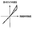
- FIG. 2A is a schematic diagram for explaining the relationship between the bending amount of the bending portion and the displacement of the first wire.
- FIG. 2B is a schematic diagram for explaining the relationship between the bending amount of the bending portion and the displacement of the second wire.
- FIG. 3A is a diagram for explaining a configuration example of the bending operation system according to the first embodiment, particularly a configuration example of a displacement detection unit, and shows a state where the bending unit is bent in a positive bending direction. It is.
- FIG. 1 is a block diagram illustrating a configuration example of the bending operation system according to the first embodiment.
- FIG. 2A is a schematic diagram for explaining the relationship between the bending amount of the bending portion and the displacement of the first wire.
- FIG. 2B is a schematic diagram for explaining the relationship between the bending amount of the bending portion and the displacement of the second wire.
- FIG. 3B is a diagram for explaining a configuration example of the bending operation system according to the first embodiment, particularly a configuration example of the displacement detection unit, and is a diagram illustrating a state where the bending unit is straight.
- FIG. 3C is a diagram for explaining a configuration example of the bending operation system according to the first embodiment, particularly a configuration example of the displacement detection unit, and shows a state where the bending unit is bent in a negative bending direction. It is.
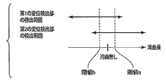
- FIG. 4 is a diagram for explaining an example of the relationship between the bending amount of the bending portion and the detection range of the displacement detection portion.
- FIG. 5A is a diagram for explaining another example of the relationship between the bending amount of the bending portion and the detection range of the displacement detection portion.
- FIG. 5B is a diagram for explaining another example of the relationship between the bending amount of the bending portion and the detection range of the displacement detection portion.
- FIG. 6A is a diagram for describing a configuration example of the bending operation system, in particular, another configuration example of the displacement detection unit, and is a diagram illustrating a state where the bending unit is bent in the positive bending direction.
- FIG. 6B is a diagram for explaining a configuration example of the bending operation system, in particular, another configuration example of the displacement detection unit, and is a diagram illustrating a state where the bending unit is straight.
- FIG. 6A is a diagram for describing a configuration example of the bending operation system, in particular, another configuration example of the displacement detection unit, and is a diagram illustrating a state where the bending unit is bent in the positive bending direction.
- FIG. 6B is a diagram for explaining a configuration example of the bending operation system, in particular, another configuration example of the displacement detection unit, and is a diagram illustrating a state where
- FIG. 6C is a diagram for explaining a configuration example of the bending operation system, in particular, another configuration example of the displacement detection unit, and is a diagram illustrating a state where the bending unit is bent in a negative bending direction.
- FIG. 7 is a flowchart illustrating an example of processing of the calculation unit in the bending motion system according to the first embodiment.
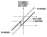
- FIG. 8 illustrates an example of the relationship between the first temporary bending amount, the second temporary bending amount, and the bending amount determined by the calculation unit with respect to the actual bending amount of the bending portion when not according to the first embodiment. It is a schematic diagram for carrying out, and is an enlarged view near the origin.
- FIG. 9 is a schematic diagram illustrating an example of the relationship between the first temporary bending amount, the second temporary bending amount, and the bending amount determined by the calculation unit with respect to the actual bending amount of the bending portion according to the first embodiment. is there.
- FIG. 10 is a schematic diagram illustrating an example of the relationship between the first temporary bending amount, the second temporary bending amount, and the bending amount determined by the calculation unit with respect to the actual bending amount of the bending portion according to the first embodiment. There is an enlarged view near the origin.
- FIG. 11 is a flowchart illustrating an example of processing of the calculation unit in the bending motion system according to the modification of the first embodiment.
- FIG. 12A is a flowchart illustrating an example of processing of a calculation unit in the bending motion system according to the second embodiment.
- FIG. 12B is a flowchart illustrating an example of processing of the calculation unit in the bending motion system according to the second embodiment, and is a continuation of FIG. 12A.
- FIG. 13 is a schematic diagram illustrating an example of the relationship between the first temporary bending amount, the second temporary bending amount, and the bending amount determined by the calculation unit with respect to the actual bending amount of the bending portion according to the second embodiment. There is an enlarged view near the origin.
- FIG. 14 is a block diagram illustrating a configuration example of the bending operation system according to the third embodiment.
- FIG. 1 shows a configuration example of a bending operation system 100 according to this embodiment.
- the bending motion system 100 has an elongated tubular portion 110.
- a curved portion 115 is provided in the vicinity of one end portion of the tubular portion 110. Further, the other end of the tubular portion 110 is connected to the grip portion 130.
- a first wire 122 and a second wire 124 are inserted into the tubular portion 110. One end of each of the first wire 122 and the second wire 124 is connected to the vicinity of the bending portion 115. The other ends of the first wire 122 and the second wire 124 are connected to each other by a chain 126 in the grip portion 130.
- a driving unit 132 is provided in the gripping unit 130.
- the drive unit 132 includes a sprocket (not shown) and a knob for rotating the sprocket.
- the sprocket teeth and the chain 126 are engaged with each other.
- the knob rotates, the sprocket also rotates and power is transmitted to the chain 126.
- the first wire 122 and the second wire 124 connected to the chain 126 are integrally displaced in the longitudinal direction, and one wire is pulled and the other wire is fed out. Since one end of the first wire 122 and the second wire 124 is connected to face the vicinity of the bending portion 115, the first wire 122 and the second wire 124 are displaced in the longitudinal direction.
- the bending portion 115 is bent in the first direction and the second direction.
- the first direction and the second direction are opposite directions.
- the bending of the bending portion 115 is defined as 0 with the bending portion 115 being straight, and the upper side in FIG. And the lower side is defined as a negative bending direction.
- the drive unit 132 is composed of a knob and a sprocket, and the knob is manually rotated by the user.
- the present invention is not limited to this, and the drive unit 132 may be configured so that the sprocket is driven by a motor or an actuator.
- the drive unit 132 may be configured to have other drive means such as an actuator for displacing the first wire 122 and the second wire 124.
- the first wire 122 and the second wire 124 do not have to be connected by the chain 126, and the power of the actuator is configured to be transmitted to the first wire and the second wire. Just do it.
- the first wire and the second wire may not be connected so that when one wire is pulled, the other wire can be freely displaced according to the bending of the bending portion 115. It only has to be configured.
- a first displacement detector 136 for detecting the displacement in the longitudinal direction of the first wire 122 and a second displacement for detecting the displacement in the longitudinal direction of the second wire 124.
- a detection unit 138 is provided.
- the first displacement detection unit 136 and the second displacement detection unit 138 in the present embodiment are encoders, for example.
- a first scale is fixed to the first wire 122
- a second scale is fixed to the second wire 124.
- the first displacement detector 136 detects the displacement of the first wire 122 by detecting the displacement of the first scale
- the second displacement detector 138 detects the displacement of the second scale.
- the displacement of the second wire 124 is detected.
- the first displacement detector 136 and the second displacement detector 138 are connected to the calculator 140, respectively.
- the calculation unit 140 calculates the shape of the bending unit 115 based on the outputs from the first displacement detection unit 136 and the second displacement detection unit 138.
- the shape of the bending portion 115 is, for example, an angle formed by tangent lines at both ends of the bending portion 115, that is, an angle formed by a tangent line at the bending start position of the bending portion 115 and a tangent line at the bending end position (hereinafter referred to as a bending amount). Or the curvature of the curved portion 115.
- the amount of bending will be described as an example of the shape of the bending portion 115.
- the calculation unit 140 is provided outside the gripping unit 130, but the calculation unit 140 may be provided inside the gripping unit 130.
- the calculation unit 140 outputs information related to the shape of the bending unit 115.
- FIG. 2A shows the relationship between the displacement of the first wire 122 and the bending amount of the bending portion 115.
- FIG. 2B shows the relationship between the displacement of the second wire 124 and the bending amount of the bending portion 115.
- the displacement of the first wire 122 and the second wire 124 is positive in the direction in which the first wire 122 is pulled and negative in the direction in which the second wire 124 is pulled.
- the bending amount of the bending portion 115 is larger when the second wire 124 is being pulled than when the first wire 122 is being pulled (the bending is The absolute value of the quantity is large).
- the bending is The absolute value of the quantity is large.
- the calculation unit 140 determines the bending amount of the bending portion 115 using both the displacement of the first wire 122 and the displacement of the second wire 124.
- the calculating unit 140 determines the bending amount of the bending portion 115 based on the displacement of the second wire 124, and the bending amount of the bending portion 115 is When negative, the bending amount of the bending portion 115 is determined based on the displacement of the first wire 122.
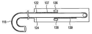
- 3A, 3B, and 3C show configuration examples related to the first displacement detection unit 136 and the second displacement detection unit 138 of the present embodiment.
- 3A schematically illustrates a state in which the bending portion 115 is curved in the positive bending direction
- FIG. 3B schematically illustrates a state in which the bending portion 115 is straight
- FIG. 3C illustrates that the bending portion 115 is negatively curved.
- the state which is curving in a direction is shown typically.
- a first scale 137 that is an encoder scale for the first displacement detector 136 is fixed to the first wire 122, and a second displacement detection is performed on the second wire 124.
- a second scale 139 that is an encoder scale for the portion 138 is fixed.
- the first scale 137 and the second scale 139 are arranged to be biased toward the chain 126 with respect to the first displacement detector 136 and the second displacement detector, respectively. That is, as shown in FIG. 3A, when the first wire 122 is pulled and the bending portion 115 is bent in the positive bending direction, the second scale 139 moves at a position facing the second displacement detection portion 138. To do. Therefore, the second displacement detector 138 measures the displacement of the second wire 124 when the first wire 122 is mainly pulled and the bending portion 115 is bent in the positive bending direction. Further, as shown in FIG.
- the first displacement detector 136 measures the displacement of the first wire 122 when the second wire 124 is mainly pulled and the bending portion 115 is bent in the negative bending direction.
- FIG. 4 shows the relationship of the detection range by the first displacement detector 136 and the first scale 137 with respect to the bending amount of the bending portion 115, and the second displacement detector 138 and the second scale with respect to the bending amount of the bending portion 115.
- 139 shows the relationship of the detection range by 139.
- the first displacement detection unit 136 and the first scale 137 include the entire range of the negative bending direction of the bending unit 115 and a first threshold value described later in the positive bending direction from the state in which the bending unit 115 is not bent. A bending amount in a range including a is detected.
- the second displacement detection unit 138 and the second scale 139 have the entire range of the bending portion 115 in the positive bending direction and the second bending direction described later from the state in which the bending portion 115 is not bent.
- the bending amount in the range including the threshold value b is detected.
- the first threshold value a is a> 0, and the second threshold value b is b ⁇ 0.
- the detection range by the first displacement detection unit 136 and the first scale 137 and the detection range by the second displacement detection unit 138 and the second scale 139 partially overlap.
- the detection range by the first displacement detection unit 136 and the first scale 137 and the detection range by the second displacement detection unit 138 and the second scale 139 are set so as not to overlap. You can also Further, as shown in FIG. 5B, the detection range by the first displacement detection unit 136 and the first scale 137 and the detection range by the second displacement detection unit 138 and the second scale 139 are both curved portions 115. It is also possible to use the entire curved range. In this case, the arrangement of the first scale 137 and the second scale 139 is as shown in FIGS. 6A, 6B, and 6C.
- the first scale 137 and the second scale 139 may interfere with other components.
- the long first scale 137 and the second scale 139 may not be arranged. Therefore, as described with reference to FIGS. 3A, 3B, 3C, and 4, the detection range by the first displacement detector 136 and the first scale 137, the second displacement detector 138, and the second By adjusting the detection range by the scale 139, the first scale 137 and the second scale 139 can be shortened, and the arrangement thereof becomes easy. As a result, the degree of freedom in designing the bending operation system 100 is improved.
- the user operates the driving unit 132 to grip the grip 130 and bend the bending portion 115 of the tubular portion 110 by a desired angle. That is, the user rotates the knob of the drive unit 132.
- the sprocket is rotated by rotating the knob, the chain 126 meshing with the sprocket is displaced.
- the first wire 122 and the second wire 124 are displaced.
- the bending portion 115 of the tubular portion 110 is bent.
- the first scale 137 fixed to the first wire 122 and the second scale 139 fixed to the second wire 124 are displaced.
- the first displacement detection unit 136 converts the displacement of the first scale 137 into an electric signal and outputs it to the calculation unit 140.
- the displacement of the first scale 137 that is, the displacement of the first wire 122 is defined as a first displacement Enc1.
- the second displacement detector 138 converts the displacement of the second scale 139 into an electrical signal and outputs the electrical signal to the calculator 140.
- the displacement of the second scale 139, that is, the displacement of the second wire 124 is referred to as a second displacement Enc2.
- step S1 the calculation unit 140 acquires the first displacement Enc1 from the first displacement detection unit 136, and acquires the second displacement Enc2 from the second displacement detection unit 138.
- step S ⁇ b> 2 the calculation unit 140 calculates a first temporary bending amount ⁇ 1 that is a temporary value of the bending amount of the bending portion 115 from the following equation (1) based on the first displacement Enc1.
- ⁇ 1 ⁇ 1 ⁇ Enc1 (1)
- the calculation unit 140 calculates the second temporary bending amount ⁇ 2 that is a temporary value of the bending amount of the bending portion 115 from the following equation (2) based on the second displacement Enc2.
- ⁇ 2 ⁇ 2 ⁇ Enc2 (2)
- ⁇ 1 and ⁇ 2 are predetermined constants.
- the constant ⁇ 1 is determined in advance based on the relationship between the displacement of the first wire 122 and the bending amount of the bending portion 115 when the bending portion 115 is bent in the negative bending direction.
- the constant ⁇ 2 is determined based on the relationship between the displacement of the second wire 124 and the bending amount of the bending portion 115 when the bending portion 115 is bent in the positive bending direction in advance. deep. Since constant ⁇ 1 and constant ⁇ 2 are generally substantially equal, one of constant ⁇ 1 and constant ⁇ 2 may be obtained and the value may be used as both constant ⁇ 1 and constant ⁇ 2.
- the relationship between the bending amount of the bending portion 115 and the first temporary bending amount ⁇ 1 or the second temporary bending amount ⁇ 2 is a simple proportional relationship. Any expression such as a higher-order expression may be used as long as the expression expresses these relationships sufficiently well.
- the relationship between the displacement of the second wire 124 and the bending amount of the bending portion 115 when the portion 115 is bent in the positive bending direction may be obtained in advance, and these relationships may be prepared as a table.
- the calculating unit 140 based on the table, from a first displacement Enc1 determining a first temporary bending amount theta 1, determines a second temporary bending amount theta 2 from the second displacement Enc2.
- the first temporary bending amount ⁇ 1 when bending in the negative bending direction, the first temporary bending amount ⁇ 1 is obtained, and when bending in the positive bending direction, the second temporary bending amount ⁇ 2 is obtained as the final bending.
- the method of setting the amount is such that when the actual bending amount of the bending portion 115 is 0 (straight), the first temporary bending amount ⁇ 1 and the second temporary bending amount ⁇ 2 coincide with each other or there is no problem in use. The difference is sufficient. However, as shown in FIG. 8, when the actual bending amount of the bending portion 115 is 0, the first temporary bending amount ⁇ 1 and the second temporary bending amount are simultaneously generated due to the structures of the tubular portion 110 and the grip portion 130.
- the bending amount not necessarily a bending amount theta 2 and becomes zero, there may be a slight deviation occurs.
- the selection of the first temporary bending amount ⁇ 1 and the second temporary bending amount ⁇ 2 is changed as a final bending amount on the condition that the bending amount is simply 0 or more, the bending amount The value of the amount may be skipped, or the change may be opposite to the actual bending direction. Therefore, the user feels uncomfortable with the change in the calculated amount of bending with respect to the amount of rotation of the operation knob. Therefore, the following algorithm is used to perform calculation so that the calculated amount of bending does not skip or a change opposite to the actual bending direction does not occur.
- Calculator 140 in step S4 on the basis of the temporary bending amount theta 2 of the first temporary bending amount theta 1 and the second, using a conversion equation selected in step S3, determines the bending amount of the bending portion 115. That is, as shown in Table 1, when ⁇ 1 ⁇ a and ⁇ 2 ⁇ a, or when b ⁇ 1 ⁇ a and ⁇ 2 ⁇ a, the second temporary bending amount ⁇ 2 is set to the bending portion 115. The amount of bending.
- the first The weighted average using the temporary bending amount ⁇ 1 and the second temporary bending amount ⁇ 2 is defined as the bending amount of the bending portion 115.
- the first temporary bending amount ⁇ 1 is set as the bending amount of the bending portion 115.
- the following expression (3) is used as an expression for obtaining a weighted average representing the bending amount ⁇ of the bending portion 115.
- ⁇ f ( ⁇ 1 , ⁇ 2 ) ⁇ ⁇ 1 + (1 ⁇ f ( ⁇ 1 , ⁇ 2 )) ⁇ ⁇ 2 (3)
- the following formula (4) can be used.
- the first provisional bending amount ⁇ 1 and the second provisional bending amount ⁇ 2 are used for the function related to the weight, but the same applies even if the first displacement Enc1 and the second displacement Enc2 are used. It is.
- the above formula (3) is represented by the following formula (5), for example.
- FIG. 9 is a schematic diagram showing the relationship between the first temporary bending amount ⁇ 1 , the second temporary bending amount ⁇ 2 , and the bending amount of the bending portion 115 determined by the calculation unit 140 with respect to the actual bending amount of the bending portion 115. And shown in FIG. FIG. 10 is a part of an enlarged view near the origin of FIG.
- the alternate long and short dash line indicates the first temporary bending amount ⁇ 1
- the broken line indicates the second temporary bending amount ⁇ 2
- the solid line indicates the bending amount of the bending portion 115 determined by the calculation unit 140.
- the completely coincident lines are actually drawn slightly shifted for easy viewing.
- the calculation unit 140 bends the first temporary bending amount ⁇ 1 based on the output of the first displacement detection unit 136 when the bending unit 115 is generally bent in the negative bending direction.
- the second temporary bending amount ⁇ 2 based on the output of the second displacement detection unit 138 is used as the bending amount of the bending portion 115.
- the bending average of the bending portion 115 is calculated by calculating a weighted average based on the first temporary bending amount ⁇ 1 and the second temporary bending amount ⁇ 2. Amount.
- step S5 the calculation unit 140 outputs the determined bending amount of the bending portion 115.
- the bending operation system 100 and other devices may display a figure or a graph representing the determined bending amount value or bending amount on a display or the like and present it to the user, for example. Further, based on the output bending amount, the bending operation system 100 and other devices may use the output bending amount for arbitrary control.
- step S ⁇ b> 6 the calculation unit 140 determines whether or not the end of the bending amount calculation process is instructed. If no termination instruction has been given, the process returns to step S1. On the other hand, if an end instruction is given, the series of processing ends.
- the bending amount of the bending portion 115 can be determined with high accuracy by determining the bending amount of the bending portion 115 as described above. That is, when the bending amount of the bending portion 115 is calculated using only one of the first displacement Enc1 of the first wire 122 and the second displacement Enc2 of the second wire 124, for example, it is derived from hysteresis. There is a possibility that the bending amount cannot be calculated because the bending amount and the displacement of the first wire 122 or the second wire 124 do not correspond to each other, or an error included in the calculated bending amount may increase. .
- the amount of bending of the bending portion 115 can be determined with high accuracy by using both the first displacement Enc1 and the second displacement Enc2. By detecting the amount of bending with high accuracy, for example, the operability of the bending portion 115 by the user can be improved, or the quality of control of the system can be improved.
- the weighted average of the temporary bending amount of the first theta 1 and based on the second and temporary bending amount theta 2 the by calculating can be coupled temporary bending amount of the 1 theta 1 and the deviation between the second temporary bending amount theta 2 smoothly. That is, for example, when the first temporary bending amount ⁇ 1 is simply negative, the first temporary bending amount ⁇ 1 is used as the bending amount of the bending portion 115, and when the first temporary bending amount ⁇ 1 is positive, the first temporary bending amount ⁇ 1 is the first amount.
- the actual bending amount of the bending portion 115 and the bending amount determined by the calculation unit 140 have a relationship as shown in FIG. Become.
- the calculation is performed even though the actual amount of bending continuously increases.
- the value of the amount of curvature determined by the portion 140 may decrease discontinuously, that is, a discontinuous reverse phenomenon may occur.
- Such discontinuity and the reversal phenomenon of the change in the amount of bending give the user a sense of incongruity when the amount of bending is presented to the user, for example.
- the bending amount determined by the calculation unit 140 is smoothly and continuously changed as described above, so that the user does not feel uncomfortable.
- the first temporary bending amount ⁇ 1 and the second temporary bending amount ⁇ 2 coincide with each other, or in use. If only varying degrees no problem does not exist, for example, when the bending amount is negative the bending amount of the first temporary bending amount theta 1 the bending portion 115, temporary bending amount of the second when the bending amount is positive theta 2 It is also possible to use a method for determining the amount of bending so that is the amount of bending of the bending portion 115. In this case, as shown in FIG.
- the first scale 137 has a length capable of measuring only a range in which the bending amount is negative
- the second scale 139 has a length capable of measuring only a range in which the bending amount is negative. It may be designed to do. As a result, the first scale 137 and the second scale 139 can be further shortened, and the degree of freedom in designing the bending operation system 100 is further improved.
- the above formulas (3) to (7) described in the present embodiment are merely examples, and other functions may be used.
- it includes between the first threshold value a and the second threshold value b, which well represents the relationship between the first temporary bending amount ⁇ 1 or the second temporary bending amount ⁇ 2 and the actual bending amount of the bending portion 115. It is conceivable to use other consecutive functions.
- the first displacement detection unit 136 and the second displacement detection unit 138 are arranged in the gripping unit 130, thereby reducing the size of the distal end side of the tubular unit 110 in which the bending unit 115 is arranged, while reducing the first side.
- the displacement of the first wire 122 and the second wire 124 can be detected.
- positioned can implement
- the first scale 137 and the second scale 139 are required for the calculation unit 140 to determine the bending amount.
- the first wire 122 and the second wire 124 are arranged only in the moving range. Accordingly, the first scale 137 and the second scale 139 can be shortened, and the degree of freedom in designing the bending operation system 100 is improved.
- the first wire 122 and the second wire 124 are connected by a chain 126, and the first wire 122 and the second wire 124 are integrally displaced in the longitudinal direction. In this way, it is not necessary to drive the first wire 122 and the second wire 124 separately.
- the first wire 122 and the second wire 124 can be displaced by simply rotating the sprocket meshed with the chain 126 using the knob, that is, the bending portion 115 can be bent.
- the user drives by a motor or the like instead of rotating the knob, it is not necessary to provide a motor for each of the first wire 122 and the second wire 124, and only one motor is provided for the sprocket. A system can be realized.
- the tubular portion 110 functions as a tubular portion having an elongated shape.
- the bending portion 115 can be bent within a predetermined movable range and functions as a bending portion included in the tubular portion.
- the first wire 122 is connected to the tubular portion at one end and functions as a first linear member that transmits power for bending the bending portion in the first direction by being displaced in the longitudinal direction.
- the second wire 124 has one end connected to the tubular portion and is displaced in the longitudinal direction, whereby the second wire 124 transmits power for bending the bending portion in a second direction that is opposite to the first direction. Functions as a linear member.
- the drive unit 132 functions as a drive unit that displaces the first linear member and the second linear member.
- the first displacement detector 136 functions as a first displacement detector that acquires the displacement of the first linear member as the first displacement.
- the second displacement detector 138 functions as a second displacement detector that acquires the displacement of the second linear member as the second displacement.
- the calculation unit 140 functions as a calculation unit that calculates the operation support information using one or both of the first displacement and the second displacement based on the state of the bending portion.
- the amount of bending functions as operation support information. For example, a position where the curved portion is straight functions as a reference position.
- the first threshold value a functions as a first bending threshold value that represents a state in which the bending portion is bent by a predetermined amount in the first direction from the reference position.
- the second threshold value b is the second threshold value b from the reference position. It functions as a second bending threshold value that represents a state of bending a predetermined amount in the direction of 2.
- the chain 126 functions as a connecting member that connects the other end of the first linear member and the other end of the second linear member.
- the first wire 122 and the second wire 124 are exemplified as the linear members, but the present invention is not limited thereto.
- the material is not limited to metal, and may be a resin or other polymer compound, and may be a linear member that transmits power by moving in the longitudinal direction.
- an encoder is used as an example of the displacement detection unit, but the present invention is not limited to this. As long as the displacement between the first wire 122 and the second wire 124 can be detected, any detector may be used.
- the tubular portion 110 is in a straight state as a reference position.
- the calculation unit 140 outputs the bending amount of the bending unit 115.
- the calculation unit 140 outputs the drive amount of the drive unit 132.
- the drive amount is an operation amount of the knob operated by the user.
- the first displacement Enc1 of the first wire 122 and the driving amount of the knob are similar to the relationship between the first displacement Enc1 and the bending amount of the bending portion 115 in the case of the first embodiment.
- the relationship is acquired in advance.
- the relationship between the second displacement Enc2 of the second wire 124 and the driving amount of the knob is acquired in advance.
- the calculation unit 140 can obtain the knob driving amount based on the first displacement Enc1 and the second displacement Enc2 using these relationships.
- step S21 the calculation unit 140 acquires the first displacement Enc1 from the first displacement detection unit 136 and acquires the second displacement Enc2 from the second displacement detection unit 138.
- step S22 the calculation unit 140 uses the relationship between the first displacement Enc1 and the knob driving amount based on the first displacement, and the first temporary driving amount D1 that is the temporary driving amount of the knob. Is calculated. Further, the calculation unit 140 uses the relationship between the second displacement Enc2 and the knob driving amount described above based on the second displacement Enc2, and the second temporary driving amount D2 that is a temporary driving amount of the knob. Is calculated.
- step S23 the calculation unit 140 refers to the following table 2 similar to that shown in, for example, Table 1 based on the first temporary drive amount D1 and the second temporary drive amount D2, in the first embodiment. As in the case of, the conversion formula is selected.
- step S24 the calculation unit 140 determines the drive amount D of the drive unit 132 based on the first temporary drive amount D1 and the second temporary drive amount D2. For example, when the first temporary drive amount D1 appropriately represents the drive amount D, the first temporary drive amount D1 is the drive amount D, and the second temporary drive amount D2 appropriately represents the drive amount D. In this case, the second temporary drive amount D2 is set as the drive amount D, and the weighted average of the first temporary drive amount D1 and the second temporary drive amount D2 is set as the drive amount D under the condition between them.
- step S25 the calculation unit 140 outputs the determined drive amount D.
- step S ⁇ b> 26 the calculation unit 140 determines whether an instruction to end the process has been input. If no end instruction has been input, the process returns to step S21. If an end instruction has been input, the process is terminated.
- the driving amount D of the driving unit 132 is output from the calculation unit 140.
- the driving amount D By presenting the driving amount D to the user, for example, the user's operation can be supported, or the driving amount D can be used for system control. Further, based on the first temporary drive amount D1 and the second temporary drive amount D2, a highly accurate drive amount can be calculated by using a value closer to the actual drive amount or taking a weighted average. It can be carried out.
- the user rotates the knob of the drive unit 132.
- the drive unit 132 may include an actuator or a motor.
- the drive amount functions as operation support information.
- various types of information can be applied to the operation support information.
- the displacement itself of the first wire 122 and the second wire 124 can be the operation support information, and the first wire 122 of the wire such as the shape of the bending portion 115, the traction force of the wire, and the stress applied to the bending portion 115.
- the value calculated based on the displacement of the second wire 124 functions as operation support information.
- the calculation unit 140 determines the bending amount of the bending portion 115 based on the combination of the value of the first temporary bending amount ⁇ 1 and the value of the second temporary bending amount ⁇ 2. Yes. On the other hand, in the present embodiment, the calculation unit 140 selects either the value of the first temporary bending amount ⁇ 1 or the second temporary bending amount ⁇ 2 as the bending amount of the bending portion 115. .
- the calculation unit 140 changes the first bending amount based on the first temporary bending amount ⁇ 1 to the first determining state based on the second temporary bending amount ⁇ 2 .
- difference temporary bending amount theta 1 and the second temporary bending amount theta 2 is a condition to be a predetermined value or less.
- step S ⁇ b> 31 the calculation unit 140 acquires the first displacement Enc1 from the first displacement detection unit 136 and acquires the second displacement Enc2 from the second displacement detection unit 138.
- step S32 the first calculating the temporary bending amount theta 1 based on the first displacement Enc1, a second for calculating the temporary bending amount theta 2 based on the second displacement Enc2.
- step S33 the calculation unit 140 determines whether or not the first temporary bending amount ⁇ 1 is smaller than zero. When the first temporary bending amount theta 1 is less than 0, the process proceeds to step S34.
- step S ⁇ b> 34 the calculation unit 140 determines the first temporary bending amount ⁇ 1 as the bending amount of the bending portion 115.
- Step calculator 140 step S35 substitutes 1 into the variable FLAG representing whether the current amount of curvature of the decision is based on a second temporary bending amount theta 2 or based on the first temporary bending amount theta 1. Thereafter, the process proceeds to step S38.
- step S33 if there is no first temporary bending amount theta 1 is less than 0, the process proceeds to step S36.
- step S ⁇ b> 36 the calculation unit 140 determines the second temporary bending amount ⁇ 2 as the bending amount of the bending portion 115.
- step S37 the calculation unit 140 assigns 2 to the variable FLAG. Thereafter, the process proceeds to step S38.
- step S ⁇ b> 38 the calculation unit 140 outputs the determined bending amount of the bending portion 115.
- step S39 the calculation unit 140 acquires the first displacement Enc1 from the first displacement detection unit 136, and acquires the second displacement Enc2 from the second displacement detection unit 138.
- step S40 the first calculating the temporary bending amount theta 1 based on the first displacement Enc1, a second for calculating the temporary bending amount theta 2 based on the second displacement Enc2.
- Step S41 140 a first provisional bending amount theta 1 and the second temporary bending amount theta 2, the first temporary bending amount theta 1 and the second temporary bending amount theta 2 which acquired this time acquired previously And calculating whether the bending amount of the bending portion 115 is increasing or decreasing, that is, whether the bending portion 115 is bending in the positive bending direction or in the negative bending direction. To do.
- Step S42 140 a first temporary bending amount theta 1 is less than the larger first threshold value a than the second threshold value b, and the second temporary bending amount theta 2 first larger than the second threshold value b It is determined whether or not the threshold value is smaller than 1.
- the process proceeds to step S43.
- the process proceeds to step S50.
- Step calculating unit 140 in S45 determines the bending amount of the bending portion 115 to the second temporary bending amount theta 2.
- step S46 the calculation unit 140 substitutes 2 for the variable FLAG. Thereafter, the process proceeds to step 55.
- step S48 the condition for determination in step S47 is satisfied
- step S50 the condition for determination in step S48
- step S49 the calculation unit 140 substitutes 1 for the variable FLAG. Thereafter, the process proceeds to step 55.
- step S50 the calculation unit 140 determines whether or not the variable FLAG is 1. If the variable FLAG is 1, i.e., when the bending amount of the bending portion 115 has first and temporary bending amount theta 1, the process proceeds to step S51. Calculator 140 in step S51 determines the bending amount of the bending portion 115 to the first temporary bending amount theta 1. In step S52, the calculation unit 140 substitutes 1 for the variable FLAG. Thereafter, the process proceeds to step 55.
- step S50 i.e., the variable FLAG is when a and bending amount of the bending portion 115 a 2 is a second temporary bending amount theta 2
- the process proceeds to step S53.
- Step calculating unit 140 in and S53 it determines the bending amount of the bending portion 115 to the second temporary bending amount theta 2.
- step S54 the calculation unit 140 substitutes 2 for the variable FLAG. Thereafter, the process proceeds to step 55.
- step S55 the calculation unit 140 outputs the determined bending amount of the bending portion 115.
- step S56 the calculation unit 140 determines whether an instruction to end the process is input. If no end instruction has been input, the process returns to step S39, and if an end instruction has been input, the process ends.
- the relationship between the first temporary bending amount ⁇ 1 , the second temporary bending amount ⁇ 2 and the bending amount of the bending portion 115 determined by the calculation unit 140 with respect to the actual bending amount of the bending portion 115 is expressed.
- the schematic diagram is as shown in FIG. FIG. 13 shows an example when the amount of bending changes from a negative direction to a positive direction.
- the first temporary bending amount theta 1 is less than the larger first threshold value a than the second threshold value b, and the second temporary bending amount theta 2 first larger than the second threshold value b 1 smaller than the threshold value a (Yes in step S42), the difference between the first temporary bending amount theta 1 and the second temporary bending amount theta 2 is smaller than the predetermined set value (Yes in step S43), the amount of curvature increases and has, and when the current bending amount has become a temporary bending amount theta 1 of the first (Yes in step S44), the amount of curvature, the the state determined based on the first temporary bending amount theta 1 2 is changed to a state determined based on the temporary bending amount ⁇ 2 of 2 .
- the first temporary bending amount ⁇ 1 is larger than the second threshold value b and smaller than the first threshold value a
- the second temporary bending amount ⁇ 2 is larger than the second threshold value b and larger than the first threshold value a.
- the discontinuity of the bending amount determined by the calculation unit 140 can be set small enough to be ignored according to the set value in step S43.
- the operability of the bending portion 115 by the user can be improved, and the quality of control of the system can be improved.
- a third embodiment will be described.
- differences from the first embodiment will be described, and the same portions will be denoted by the same reference numerals and description thereof will be omitted.
- the bending operation can be performed in two directions in which the bending portion 115 is orthogonal. That is, it can bend in the first and second directions, and further bend in the third and fourth directions, which are directions orthogonal to the first and second directions.
- the first and second directions are opposite directions
- the third and fourth directions are opposite directions.
- the bending portion 115 can be bent not only in two orthogonal directions but also in all directions by a combination of bending operations in two orthogonal directions. However, it can be bent only in two orthogonal bending directions. In the third embodiment, the bending operation can be performed in two orthogonal directions, but the two directions may not be orthogonal.
- FIG. 14 shows an outline of a configuration example of the bending operation system 200 according to the present embodiment.
- the bending operation system 200 includes the following in addition to the bending operation system 100 according to the first embodiment. That is, the curves in the third and fourth directions orthogonal to the curves in the first and second directions curved by the first wire 122 and the second wire 124 are provided.
- the bending operation system 200 includes a third wire 222 and a fourth wire 224 for bending the bending portion 115 in the second direction.
- the third wire 222 and the fourth wire 224 the first wire 122 and the second wire 124 are connected by a chain 126 (hereinafter, this chain is referred to as the first chain 126).
- the second chain 226 meshes with a second sprocket provided in the drive unit 132, and the second sprocket is connected to the second knob.
- the second knob of the drive unit 132 When the user rotates the second knob of the drive unit 132, the second sprocket is rotated, and the second chain 226 is displaced.
- the third wire 222 and the fourth wire 224 With the displacement of the second chain 226, the third wire 222 and the fourth wire 224 are displaced, and the bending portion 115 is bent in the third or fourth direction.
- the third wire 222, the fourth wire 224, and the second chain 226 correspond to the first wire 122, the second wire 124, and the first chain 126, respectively, and are similar to them.
- the bending operation system 200 includes a third displacement detector 236 for detecting the displacement of the third wire 222.
- the third displacement detector 236 is an encoder, for example, and an encoder scale (not shown) is fixed to the third wire 222.
- the third displacement detector 236 outputs data relating to the displacement of the third wire 222 to the calculator 140.
- the bending motion system 200 includes a fourth displacement detector 238 for detecting the displacement of the fourth wire 224.
- the fourth displacement detector 238 is, for example, an encoder, and an encoder scale (not shown) is fixed to the fourth wire 224.
- the fourth displacement detector 238 outputs data related to the displacement of the fourth wire 224 to the calculator 140.
- the third displacement detector 236 and the fourth displacement detector 238 correspond to the first displacement detector 136 and the second displacement detector 138, respectively, and function in the same manner.
- the calculation unit 140 calculates the amount of bending in the third and fourth directions in the same manner as in the first embodiment described with reference to FIGS. 7 to 10. Calculation is based on the output of the displacement detector 238. According to the present embodiment, the bending of the bending portion 115 and the determination of the bending amount function in the same manner as in the first embodiment, and the same effect can be obtained.
- the bending portion 115 is freely bent in the first and second directions and the third and fourth directions, so that the bending portion 115 is bent in any direction with respect to directions other than the twist with respect to the bending portion 115.
- the portion 115 can be curved.
- the third wire 222 has one end connected to the tubular portion and is displaced in the longitudinal direction, whereby the bending portion is bent in a third direction different from the first direction and the second direction. It functions as a third linear member that transmits the power to be moved.
- the fourth wire 224 has a first end connected to the tubular portion and is displaced in the longitudinal direction to transmit power for bending the bending portion in a fourth direction that is opposite to the third direction. It functions as a linear member.
- the third displacement detector 236 functions as a third displacement detector that acquires the displacement of the third linear member as the third displacement.
- the fourth displacement detector 238 functions as a fourth displacement detector that acquires the displacement of the fourth linear member as the fourth displacement.
- the present invention is not limited to the above-described embodiment as it is, and can be embodied by modifying constituent elements without departing from the scope of the invention in the implementation stage.
- various inventions can be formed by appropriately combining a plurality of components disclosed in the embodiment. For example, even if some constituent elements are deleted from all the constituent elements shown in the embodiment, the problem described in the column of problems to be solved by the invention can be solved and the effect of the invention can be obtained. The configuration in which this component is deleted can also be extracted as an invention.
- constituent elements over different embodiments may be appropriately combined.
Priority Applications (3)
| Application Number | Priority Date | Filing Date | Title |
|---|---|---|---|
| CN201280049992.6A CN103874449B (zh) | 2011-10-14 | 2012-10-12 | 弯曲动作系统 |
| EP12839517.5A EP2767211A4 (en) | 2011-10-14 | 2012-10-12 | BENDING OPERATING SYSTEM |
| US14/252,029 US9829082B2 (en) | 2011-10-14 | 2014-04-14 | Bending operation system |
Applications Claiming Priority (2)
| Application Number | Priority Date | Filing Date | Title |
|---|---|---|---|
| JP2011-227113 | 2011-10-14 | ||
| JP2011227113A JP6012950B2 (ja) | 2011-10-14 | 2011-10-14 | 湾曲動作システム |
Related Child Applications (1)
| Application Number | Title | Priority Date | Filing Date |
|---|---|---|---|
| US14/252,029 Continuation-In-Part US9829082B2 (en) | 2011-10-14 | 2014-04-14 | Bending operation system |
Publications (1)
| Publication Number | Publication Date |
|---|---|
| WO2013054907A1 true WO2013054907A1 (ja) | 2013-04-18 |
Family
ID=48081952
Family Applications (1)
| Application Number | Title | Priority Date | Filing Date |
|---|---|---|---|
| PCT/JP2012/076495 WO2013054907A1 (ja) | 2011-10-14 | 2012-10-12 | 湾曲動作システム |
Country Status (5)
| Country | Link |
|---|---|
| US (1) | US9829082B2 (zh) |
| EP (1) | EP2767211A4 (zh) |
| JP (1) | JP6012950B2 (zh) |
| CN (1) | CN103874449B (zh) |
| WO (1) | WO2013054907A1 (zh) |
Cited By (2)
| Publication number | Priority date | Publication date | Assignee | Title |
|---|---|---|---|---|
| EP3085296A4 (en) * | 2013-12-19 | 2017-09-13 | Olympus Corporation | Insertion device |
| WO2019207674A1 (ja) * | 2018-04-25 | 2019-10-31 | オリンパス株式会社 | 駆動装置および医療用マニピュレータ |
Families Citing this family (11)
| Publication number | Priority date | Publication date | Assignee | Title |
|---|---|---|---|---|
| JP2009516574A (ja) * | 2005-11-22 | 2009-04-23 | ネオガイド システムズ, インコーポレイテッド | 曲げ可能な装置の形状を決定する方法 |
| US10314463B2 (en) * | 2014-10-24 | 2019-06-11 | Auris Health, Inc. | Automated endoscope calibration |
| DE112014007269T5 (de) * | 2014-12-19 | 2017-10-12 | Olympus Corporation | Einfügung/Entfernung-Unterstützungsapparat und Einfügung/Entfernung-Unterstützungsverfahren |
| DE112014007268B4 (de) * | 2014-12-19 | 2019-02-07 | Olympus Corporation | Einfügung/Entfernung-Unterstützungsapparat und Einfügung/Entfernung-Unterstützungsverfahren |
| DE112016006985T5 (de) * | 2016-06-20 | 2019-02-28 | Olympus Corporation | Einführvorrichtung für einen flexiblen Tubus |
| CN109715037B (zh) * | 2016-09-21 | 2022-09-06 | 直观外科手术操作公司 | 用于器械弯折检测的系统和方法 |
| CN106773007B (zh) * | 2017-02-24 | 2020-04-07 | 深圳市古安泰自动化技术有限公司 | 工业内窥镜 |
| DE102019111101A1 (de) * | 2019-04-30 | 2020-11-05 | Karl Storz Se & Co. Kg | Endoskopische Vorrichtung |
| JPWO2021201081A1 (zh) * | 2020-03-31 | 2021-10-07 | ||
| USD964284S1 (en) | 2021-01-21 | 2022-09-20 | Gs Yuasa International Ltd. | Grid base plate for lead storage battery |
| WO2023021538A1 (ja) * | 2021-08-16 | 2023-02-23 | オリンパスメディカルシステムズ株式会社 | マニピュレータシステム、制御装置及び形状推定方法 |
Citations (3)
| Publication number | Priority date | Publication date | Assignee | Title |
|---|---|---|---|---|
| JPS6187530A (ja) | 1984-10-05 | 1986-05-02 | オリンパス光学工業株式会社 | 内視鏡 |
| JPH0316901U (zh) * | 1989-07-03 | 1991-02-20 | ||
| JP2002264048A (ja) * | 2001-03-08 | 2002-09-18 | Hitachi Ltd | 被牽引機構の位置決め制御装置 |
Family Cites Families (20)
| Publication number | Priority date | Publication date | Assignee | Title |
|---|---|---|---|---|
| JP3397940B2 (ja) * | 1995-06-30 | 2003-04-21 | オリンパス光学工業株式会社 | 電動湾曲内視鏡装置 |
| JP2001275941A (ja) * | 2000-03-31 | 2001-10-09 | Olympus Optical Co Ltd | 電動湾曲内視鏡装置 |
| US6669629B2 (en) * | 2001-04-24 | 2003-12-30 | Olympus Optical Co., Ltd. | Endoscope system comprising an electrically bendable endoscope |
| JP3973504B2 (ja) * | 2002-07-15 | 2007-09-12 | 株式会社日立製作所 | 牽引位置決め装置 |
| JP4169549B2 (ja) * | 2002-09-06 | 2008-10-22 | オリンパス株式会社 | 内視鏡 |
| JP4695420B2 (ja) * | 2004-09-27 | 2011-06-08 | オリンパス株式会社 | 湾曲制御装置 |
| WO2007013350A1 (ja) * | 2005-07-25 | 2007-02-01 | Olympus Medical Systems Corp. | 医療用制御装置 |
| US20070106114A1 (en) * | 2005-11-09 | 2007-05-10 | Pentax Corporation | Endoscope-shape monitoring system |
| JP5030639B2 (ja) * | 2007-03-29 | 2012-09-19 | オリンパスメディカルシステムズ株式会社 | 内視鏡装置の処置具位置制御装置 |
| JP5160549B2 (ja) * | 2007-09-11 | 2013-03-13 | オリンパス株式会社 | 内視鏡装置 |
| EP2215960B1 (en) * | 2007-11-29 | 2017-12-27 | Olympus Corporation | Endoscope curve control apparatus |
| JP4759654B2 (ja) * | 2008-10-28 | 2011-08-31 | オリンパスメディカルシステムズ株式会社 | 医療機器 |
| WO2011040104A1 (ja) * | 2009-09-30 | 2011-04-07 | オリンパスメディカルシステムズ株式会社 | 内視鏡装置及び湾曲駆動制御方法 |
| EP2382939B1 (en) * | 2009-11-10 | 2013-09-04 | Olympus Medical Systems Corp. | Multi-joint manipulator device and endoscope system having the same |
| JP5052698B2 (ja) * | 2009-11-18 | 2012-10-17 | オリンパスメディカルシステムズ株式会社 | 医療装置 |
| JP4914953B2 (ja) * | 2010-03-02 | 2012-04-11 | オリンパスメディカルシステムズ株式会社 | 医療システム及び制御方法 |
| WO2012014532A1 (ja) * | 2010-07-28 | 2012-02-02 | オリンパスメディカルシステムズ株式会社 | 内視鏡と、この内視鏡の挿通湾曲方法 |
| CN103153161B (zh) * | 2011-03-29 | 2015-12-02 | 奥林巴斯株式会社 | 内窥镜 |
| CN103068297B (zh) * | 2011-03-30 | 2015-12-02 | 奥林巴斯株式会社 | 内窥镜系统 |
| CN103140159A (zh) * | 2011-05-12 | 2013-06-05 | 奥林巴斯医疗株式会社 | 医疗用控制装置 |
-
2011
- 2011-10-14 JP JP2011227113A patent/JP6012950B2/ja active Active
-
2012
- 2012-10-12 WO PCT/JP2012/076495 patent/WO2013054907A1/ja active Application Filing
- 2012-10-12 EP EP12839517.5A patent/EP2767211A4/en not_active Withdrawn
- 2012-10-12 CN CN201280049992.6A patent/CN103874449B/zh active Active
-
2014
- 2014-04-14 US US14/252,029 patent/US9829082B2/en active Active
Patent Citations (3)
| Publication number | Priority date | Publication date | Assignee | Title |
|---|---|---|---|---|
| JPS6187530A (ja) | 1984-10-05 | 1986-05-02 | オリンパス光学工業株式会社 | 内視鏡 |
| JPH0316901U (zh) * | 1989-07-03 | 1991-02-20 | ||
| JP2002264048A (ja) * | 2001-03-08 | 2002-09-18 | Hitachi Ltd | 被牽引機構の位置決め制御装置 |
Non-Patent Citations (1)
| Title |
|---|
| See also references of EP2767211A4 |
Cited By (3)
| Publication number | Priority date | Publication date | Assignee | Title |
|---|---|---|---|---|
| EP3085296A4 (en) * | 2013-12-19 | 2017-09-13 | Olympus Corporation | Insertion device |
| US10302933B2 (en) | 2013-12-19 | 2019-05-28 | Olympus Corporation | Insertion apparatus |
| WO2019207674A1 (ja) * | 2018-04-25 | 2019-10-31 | オリンパス株式会社 | 駆動装置および医療用マニピュレータ |
Also Published As
| Publication number | Publication date |
|---|---|
| CN103874449A (zh) | 2014-06-18 |
| JP6012950B2 (ja) | 2016-10-25 |
| CN103874449B (zh) | 2016-08-17 |
| JP2013085616A (ja) | 2013-05-13 |
| EP2767211A1 (en) | 2014-08-20 |
| US9829082B2 (en) | 2017-11-28 |
| US20140222214A1 (en) | 2014-08-07 |
| EP2767211A4 (en) | 2015-06-03 |
Similar Documents
| Publication | Publication Date | Title |
|---|---|---|
| WO2013054907A1 (ja) | 湾曲動作システム | |
| US10155316B2 (en) | Manipulator-calibrating method, manipulator, and manipulator system | |
| EP2517613B1 (en) | Endoscope system | |
| US10172600B2 (en) | Insertion apparatus | |
| US7348751B2 (en) | Apparatus for deciding position of traction | |
| US8382659B2 (en) | Endoscope apparatus and controlling method thereof comprising curving control mechanism | |
| EP2671499B1 (en) | Endoscope | |
| JP2018008335A (ja) | 連続体ロボット、その運動学の補正方法、および連続体ロボットの制御方法 | |
| US20160081530A1 (en) | Endoscope system | |
| JP6496842B2 (ja) | 可撓管挿入装置 | |
| EP2873362B1 (en) | Insertion device | |
| JP2007130175A (ja) | 内視鏡挿入部形状把握システム | |
| JP5078565B2 (ja) | 牽引装置 | |
| WO2016181484A1 (ja) | 可撓管挿入装置 | |
| JP7167127B2 (ja) | 可撓管挿入装置、剛性制御装置、挿入部の挿入方法、及び剛性制御プログラムを記録した記録媒体 | |
| JP6177485B1 (ja) | マニピュレータシステム | |
| US8717427B2 (en) | Endoscope | |
| JP2006192056A (ja) | 電動湾曲式内視鏡 | |
| JP5396178B2 (ja) | 内視鏡装置及び内視鏡システム | |
| WO2023162628A1 (ja) | 操作システムおよび操作システムの制御方法 | |
| JP2011019550A (ja) | 内視鏡装置及び内視鏡システム並びに内視鏡装置の制御方法 | |
| JP2013022184A (ja) | 内視鏡 | |
| WO2016136473A1 (ja) | 医療用マニピュレータシステム |
Legal Events
| Date | Code | Title | Description |
|---|---|---|---|
| 121 | Ep: the epo has been informed by wipo that ep was designated in this application |
Ref document number: 12839517 Country of ref document: EP Kind code of ref document: A1 |
|
| NENP | Non-entry into the national phase |
Ref country code: DE |
|
| WWE | Wipo information: entry into national phase |
Ref document number: 2012839517 Country of ref document: EP |