WO2013054723A1 - 搬送台車 - Google Patents
搬送台車 Download PDFInfo
- Publication number
- WO2013054723A1 WO2013054723A1 PCT/JP2012/075728 JP2012075728W WO2013054723A1 WO 2013054723 A1 WO2013054723 A1 WO 2013054723A1 JP 2012075728 W JP2012075728 W JP 2012075728W WO 2013054723 A1 WO2013054723 A1 WO 2013054723A1
- Authority
- WO
- WIPO (PCT)
- Prior art keywords
- current
- electric actuator
- controller
- electric
- body frame
- Prior art date
- Legal status (The legal status is an assumption and is not a legal conclusion. Google has not performed a legal analysis and makes no representation as to the accuracy of the status listed.)
- Ceased
Links
Images


Classifications
-
- B—PERFORMING OPERATIONS; TRANSPORTING
- B62—LAND VEHICLES FOR TRAVELLING OTHERWISE THAN ON RAILS
- B62B—HAND-PROPELLED VEHICLES, e.g. HAND CARTS OR PERAMBULATORS; SLEDGES
- B62B5/00—Accessories or details specially adapted for hand carts
-
- B—PERFORMING OPERATIONS; TRANSPORTING
- B60—VEHICLES IN GENERAL
- B60L—PROPULSION OF ELECTRICALLY-PROPELLED VEHICLES; SUPPLYING ELECTRIC POWER FOR AUXILIARY EQUIPMENT OF ELECTRICALLY-PROPELLED VEHICLES; ELECTRODYNAMIC BRAKE SYSTEMS FOR VEHICLES IN GENERAL; MAGNETIC SUSPENSION OR LEVITATION FOR VEHICLES; MONITORING OPERATING VARIABLES OF ELECTRICALLY-PROPELLED VEHICLES; ELECTRIC SAFETY DEVICES FOR ELECTRICALLY-PROPELLED VEHICLES
- B60L1/00—Supplying electric power to auxiliary equipment of vehicles
- B60L1/003—Supplying electric power to auxiliary equipment of vehicles to auxiliary motors, e.g. for pumps, compressors
-
- B—PERFORMING OPERATIONS; TRANSPORTING
- B60—VEHICLES IN GENERAL
- B60L—PROPULSION OF ELECTRICALLY-PROPELLED VEHICLES; SUPPLYING ELECTRIC POWER FOR AUXILIARY EQUIPMENT OF ELECTRICALLY-PROPELLED VEHICLES; ELECTRODYNAMIC BRAKE SYSTEMS FOR VEHICLES IN GENERAL; MAGNETIC SUSPENSION OR LEVITATION FOR VEHICLES; MONITORING OPERATING VARIABLES OF ELECTRICALLY-PROPELLED VEHICLES; ELECTRIC SAFETY DEVICES FOR ELECTRICALLY-PROPELLED VEHICLES
- B60L15/00—Methods, circuits, or devices for controlling the traction-motor speed of electrically-propelled vehicles
- B60L15/20—Methods, circuits, or devices for controlling the traction-motor speed of electrically-propelled vehicles for control of the vehicle or its driving motor to achieve a desired performance, e.g. speed, torque, programmed variation of speed
-
- B—PERFORMING OPERATIONS; TRANSPORTING
- B60—VEHICLES IN GENERAL
- B60L—PROPULSION OF ELECTRICALLY-PROPELLED VEHICLES; SUPPLYING ELECTRIC POWER FOR AUXILIARY EQUIPMENT OF ELECTRICALLY-PROPELLED VEHICLES; ELECTRODYNAMIC BRAKE SYSTEMS FOR VEHICLES IN GENERAL; MAGNETIC SUSPENSION OR LEVITATION FOR VEHICLES; MONITORING OPERATING VARIABLES OF ELECTRICALLY-PROPELLED VEHICLES; ELECTRIC SAFETY DEVICES FOR ELECTRICALLY-PROPELLED VEHICLES
- B60L50/00—Electric propulsion with power supplied within the vehicle
- B60L50/50—Electric propulsion with power supplied within the vehicle using propulsion power supplied by batteries or fuel cells
- B60L50/51—Electric propulsion with power supplied within the vehicle using propulsion power supplied by batteries or fuel cells characterised by AC-motors
-
- B—PERFORMING OPERATIONS; TRANSPORTING
- B60—VEHICLES IN GENERAL
- B60L—PROPULSION OF ELECTRICALLY-PROPELLED VEHICLES; SUPPLYING ELECTRIC POWER FOR AUXILIARY EQUIPMENT OF ELECTRICALLY-PROPELLED VEHICLES; ELECTRODYNAMIC BRAKE SYSTEMS FOR VEHICLES IN GENERAL; MAGNETIC SUSPENSION OR LEVITATION FOR VEHICLES; MONITORING OPERATING VARIABLES OF ELECTRICALLY-PROPELLED VEHICLES; ELECTRIC SAFETY DEVICES FOR ELECTRICALLY-PROPELLED VEHICLES
- B60L50/00—Electric propulsion with power supplied within the vehicle
- B60L50/50—Electric propulsion with power supplied within the vehicle using propulsion power supplied by batteries or fuel cells
- B60L50/60—Electric propulsion with power supplied within the vehicle using propulsion power supplied by batteries or fuel cells using power supplied by batteries
- B60L50/66—Arrangements of batteries
-
- B—PERFORMING OPERATIONS; TRANSPORTING
- B62—LAND VEHICLES FOR TRAVELLING OTHERWISE THAN ON RAILS
- B62B—HAND-PROPELLED VEHICLES, e.g. HAND CARTS OR PERAMBULATORS; SLEDGES
- B62B3/00—Hand carts having more than one axis carrying transport wheels; Steering devices therefor; Equipment therefor
- B62B3/02—Hand carts having more than one axis carrying transport wheels; Steering devices therefor; Equipment therefor involving parts being adjustable, collapsible, attachable, detachable or convertible
-
- B—PERFORMING OPERATIONS; TRANSPORTING
- B62—LAND VEHICLES FOR TRAVELLING OTHERWISE THAN ON RAILS
- B62B—HAND-PROPELLED VEHICLES, e.g. HAND CARTS OR PERAMBULATORS; SLEDGES
- B62B5/00—Accessories or details specially adapted for hand carts
- B62B5/0026—Propulsion aids
- B62B5/0033—Electric motors
-
- B—PERFORMING OPERATIONS; TRANSPORTING
- B62—LAND VEHICLES FOR TRAVELLING OTHERWISE THAN ON RAILS
- B62B—HAND-PROPELLED VEHICLES, e.g. HAND CARTS OR PERAMBULATORS; SLEDGES
- B62B5/00—Accessories or details specially adapted for hand carts
- B62B5/0026—Propulsion aids
- B62B5/0069—Control
-
- B—PERFORMING OPERATIONS; TRANSPORTING
- B62—LAND VEHICLES FOR TRAVELLING OTHERWISE THAN ON RAILS
- B62B—HAND-PROPELLED VEHICLES, e.g. HAND CARTS OR PERAMBULATORS; SLEDGES
- B62B5/00—Accessories or details specially adapted for hand carts
- B62B5/0026—Propulsion aids
- B62B5/0069—Control
- B62B5/0073—Measuring a force
-
- B—PERFORMING OPERATIONS; TRANSPORTING
- B66—HOISTING; LIFTING; HAULING
- B66F—HOISTING, LIFTING, HAULING OR PUSHING, NOT OTHERWISE PROVIDED FOR, e.g. DEVICES WHICH APPLY A LIFTING OR PUSHING FORCE DIRECTLY TO THE SURFACE OF A LOAD
- B66F9/00—Devices for lifting or lowering bulky or heavy goods for loading or unloading purposes
- B66F9/06—Devices for lifting or lowering bulky or heavy goods for loading or unloading purposes movable, with their loads, on wheels or the like, e.g. fork-lift trucks
- B66F9/065—Devices for lifting or lowering bulky or heavy goods for loading or unloading purposes movable, with their loads, on wheels or the like, e.g. fork-lift trucks non-masted
-
- B—PERFORMING OPERATIONS; TRANSPORTING
- B66—HOISTING; LIFTING; HAULING
- B66F—HOISTING, LIFTING, HAULING OR PUSHING, NOT OTHERWISE PROVIDED FOR, e.g. DEVICES WHICH APPLY A LIFTING OR PUSHING FORCE DIRECTLY TO THE SURFACE OF A LOAD
- B66F9/00—Devices for lifting or lowering bulky or heavy goods for loading or unloading purposes
- B66F9/06—Devices for lifting or lowering bulky or heavy goods for loading or unloading purposes movable, with their loads, on wheels or the like, e.g. fork-lift trucks
- B66F9/075—Constructional features or details
- B66F9/07586—Suspension or mounting of wheels on chassis
-
- B—PERFORMING OPERATIONS; TRANSPORTING
- B66—HOISTING; LIFTING; HAULING
- B66F—HOISTING, LIFTING, HAULING OR PUSHING, NOT OTHERWISE PROVIDED FOR, e.g. DEVICES WHICH APPLY A LIFTING OR PUSHING FORCE DIRECTLY TO THE SURFACE OF A LOAD
- B66F9/00—Devices for lifting or lowering bulky or heavy goods for loading or unloading purposes
- B66F9/06—Devices for lifting or lowering bulky or heavy goods for loading or unloading purposes movable, with their loads, on wheels or the like, e.g. fork-lift trucks
- B66F9/075—Constructional features or details
- B66F9/20—Means for actuating or controlling masts, platforms, or forks
- B66F9/22—Hydraulic devices or systems
-
- B—PERFORMING OPERATIONS; TRANSPORTING
- B60—VEHICLES IN GENERAL
- B60L—PROPULSION OF ELECTRICALLY-PROPELLED VEHICLES; SUPPLYING ELECTRIC POWER FOR AUXILIARY EQUIPMENT OF ELECTRICALLY-PROPELLED VEHICLES; ELECTRODYNAMIC BRAKE SYSTEMS FOR VEHICLES IN GENERAL; MAGNETIC SUSPENSION OR LEVITATION FOR VEHICLES; MONITORING OPERATING VARIABLES OF ELECTRICALLY-PROPELLED VEHICLES; ELECTRIC SAFETY DEVICES FOR ELECTRICALLY-PROPELLED VEHICLES
- B60L2200/00—Type of vehicles
- B60L2200/30—Trolleys
-
- B—PERFORMING OPERATIONS; TRANSPORTING
- B60—VEHICLES IN GENERAL
- B60L—PROPULSION OF ELECTRICALLY-PROPELLED VEHICLES; SUPPLYING ELECTRIC POWER FOR AUXILIARY EQUIPMENT OF ELECTRICALLY-PROPELLED VEHICLES; ELECTRODYNAMIC BRAKE SYSTEMS FOR VEHICLES IN GENERAL; MAGNETIC SUSPENSION OR LEVITATION FOR VEHICLES; MONITORING OPERATING VARIABLES OF ELECTRICALLY-PROPELLED VEHICLES; ELECTRIC SAFETY DEVICES FOR ELECTRICALLY-PROPELLED VEHICLES
- B60L2240/00—Control parameters of input or output; Target parameters
- B60L2240/40—Drive Train control parameters
- B60L2240/42—Drive Train control parameters related to electric machines
- B60L2240/423—Torque
-
- B—PERFORMING OPERATIONS; TRANSPORTING
- B60—VEHICLES IN GENERAL
- B60L—PROPULSION OF ELECTRICALLY-PROPELLED VEHICLES; SUPPLYING ELECTRIC POWER FOR AUXILIARY EQUIPMENT OF ELECTRICALLY-PROPELLED VEHICLES; ELECTRODYNAMIC BRAKE SYSTEMS FOR VEHICLES IN GENERAL; MAGNETIC SUSPENSION OR LEVITATION FOR VEHICLES; MONITORING OPERATING VARIABLES OF ELECTRICALLY-PROPELLED VEHICLES; ELECTRIC SAFETY DEVICES FOR ELECTRICALLY-PROPELLED VEHICLES
- B60L2250/00—Driver interactions
- B60L2250/16—Driver interactions by display
-
- B—PERFORMING OPERATIONS; TRANSPORTING
- B60—VEHICLES IN GENERAL
- B60L—PROPULSION OF ELECTRICALLY-PROPELLED VEHICLES; SUPPLYING ELECTRIC POWER FOR AUXILIARY EQUIPMENT OF ELECTRICALLY-PROPELLED VEHICLES; ELECTRODYNAMIC BRAKE SYSTEMS FOR VEHICLES IN GENERAL; MAGNETIC SUSPENSION OR LEVITATION FOR VEHICLES; MONITORING OPERATING VARIABLES OF ELECTRICALLY-PROPELLED VEHICLES; ELECTRIC SAFETY DEVICES FOR ELECTRICALLY-PROPELLED VEHICLES
- B60L2270/00—Problem solutions or means not otherwise provided for
- B60L2270/10—Emission reduction
- B60L2270/14—Emission reduction of noise
- B60L2270/145—Structure borne vibrations
-
- B—PERFORMING OPERATIONS; TRANSPORTING
- B62—LAND VEHICLES FOR TRAVELLING OTHERWISE THAN ON RAILS
- B62B—HAND-PROPELLED VEHICLES, e.g. HAND CARTS OR PERAMBULATORS; SLEDGES
- B62B2203/00—Grasping, holding, supporting the objects
- B62B2203/10—Grasping, holding, supporting the objects comprising lifting means
-
- B—PERFORMING OPERATIONS; TRANSPORTING
- B62—LAND VEHICLES FOR TRAVELLING OTHERWISE THAN ON RAILS
- B62B—HAND-PROPELLED VEHICLES, e.g. HAND CARTS OR PERAMBULATORS; SLEDGES
- B62B3/00—Hand carts having more than one axis carrying transport wheels; Steering devices therefor; Equipment therefor
- B62B3/04—Hand carts having more than one axis carrying transport wheels; Steering devices therefor; Equipment therefor involving means for grappling or securing in place objects to be carried; Loading or unloading equipment
-
- B—PERFORMING OPERATIONS; TRANSPORTING
- B62—LAND VEHICLES FOR TRAVELLING OTHERWISE THAN ON RAILS
- B62B—HAND-PROPELLED VEHICLES, e.g. HAND CARTS OR PERAMBULATORS; SLEDGES
- B62B5/00—Accessories or details specially adapted for hand carts
- B62B5/04—Braking mechanisms; Locking devices against movement
-
- Y—GENERAL TAGGING OF NEW TECHNOLOGICAL DEVELOPMENTS; GENERAL TAGGING OF CROSS-SECTIONAL TECHNOLOGIES SPANNING OVER SEVERAL SECTIONS OF THE IPC; TECHNICAL SUBJECTS COVERED BY FORMER USPC CROSS-REFERENCE ART COLLECTIONS [XRACs] AND DIGESTS
- Y02—TECHNOLOGIES OR APPLICATIONS FOR MITIGATION OR ADAPTATION AGAINST CLIMATE CHANGE
- Y02T—CLIMATE CHANGE MITIGATION TECHNOLOGIES RELATED TO TRANSPORTATION
- Y02T10/00—Road transport of goods or passengers
- Y02T10/60—Other road transportation technologies with climate change mitigation effect
- Y02T10/64—Electric machine technologies in electromobility
-
- Y—GENERAL TAGGING OF NEW TECHNOLOGICAL DEVELOPMENTS; GENERAL TAGGING OF CROSS-SECTIONAL TECHNOLOGIES SPANNING OVER SEVERAL SECTIONS OF THE IPC; TECHNICAL SUBJECTS COVERED BY FORMER USPC CROSS-REFERENCE ART COLLECTIONS [XRACs] AND DIGESTS
- Y02—TECHNOLOGIES OR APPLICATIONS FOR MITIGATION OR ADAPTATION AGAINST CLIMATE CHANGE
- Y02T—CLIMATE CHANGE MITIGATION TECHNOLOGIES RELATED TO TRANSPORTATION
- Y02T10/00—Road transport of goods or passengers
- Y02T10/60—Other road transportation technologies with climate change mitigation effect
- Y02T10/70—Energy storage systems for electromobility, e.g. batteries
-
- Y—GENERAL TAGGING OF NEW TECHNOLOGICAL DEVELOPMENTS; GENERAL TAGGING OF CROSS-SECTIONAL TECHNOLOGIES SPANNING OVER SEVERAL SECTIONS OF THE IPC; TECHNICAL SUBJECTS COVERED BY FORMER USPC CROSS-REFERENCE ART COLLECTIONS [XRACs] AND DIGESTS
- Y02—TECHNOLOGIES OR APPLICATIONS FOR MITIGATION OR ADAPTATION AGAINST CLIMATE CHANGE
- Y02T—CLIMATE CHANGE MITIGATION TECHNOLOGIES RELATED TO TRANSPORTATION
- Y02T10/00—Road transport of goods or passengers
- Y02T10/60—Other road transportation technologies with climate change mitigation effect
- Y02T10/72—Electric energy management in electromobility
Definitions
- the present invention relates to a transport carriage capable of transporting loaded cargo.
- a transport cart that can be moved while the load is mounted is used.
- JP 2004-35239A discloses a movable lifting device capable of lifting and lowering an article placed on a lifting body to a predetermined height.
- this lifting device the lifting body is lifted and lowered by a motor drive.
- the present invention has been made in view of the above-described problems, and an object thereof is to improve the reliability of the lifting device in the transport carriage.
- a transport cart capable of transporting a loaded load, the vehicle body frame supported by the wheels, and the load mounted on the vehicle body frame so as to be movable up and down.
- a loading platform an electric actuator that is electrically driven to extend and contract to raise and lower the loading platform; and a controller that supplies current to the electric actuator, wherein the controller has a continuous drive time of a predetermined time or more.
- a transport carriage that stops the supply of current to the electric actuator is provided.
- FIG. 1 is a perspective view of a transport cart according to an embodiment of the present invention.
- FIG. 2 is a side view of FIG.
- FIG. 3 is a front view of FIG.
- FIG. 4 is a control block diagram of the transport carriage.
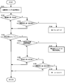
- FIG. 5 is a flowchart for explaining a fail-safe operation in the transport cart.
- the transport cart 100 is used for transporting the loaded cargo in a factory, for example.
- the transport cart 100 travels with the driving force applied by the operator being assisted by the assist force generated by the rotation of the electric motor 15 described later.
- the transport cart 100 is an electric assist cart having an electric assist function here, but may be a normal cart having no electric assist function.
- the transport cart 100 is a vehicle body frame 1, a cargo bed 3 that can be moved up and down with respect to the vehicle body frame 1, and an operation unit that can input driving force from two places on the left and right of the vehicle body frame 1.
- An operation handle 5 a pair of drive wheels 11 provided on the left and right sides of the vehicle body frame 1 with a space therebetween, and a pair of universal wheels 12 mounted on the vehicle body frame 1 and provided behind the drive wheels 11 are provided.
- the drive wheel 11 is a front wheel of the transport cart 100
- the universal wheel 12 is a rear wheel of the transport cart 100. These drive wheel 11 and universal wheel 12 correspond to wheels.
- the body frame 1 is a frame in which square pipe materials are combined.
- the body frame 1 is supported by the drive wheels 11 and the universal wheels 12.
- the body frame 1 is erected on a flat surface portion 1a on which a load is placed via a loading platform 3, a lower projecting portion 1b projecting at a lower portion of the flat surface portion 1a, and an upper rear end of the flat surface portion 1a. And a standing portion 1c.
- the loading platform 3 is a flat plate with an edge provided so as to cover the upper portion of the flat portion 1a in the body frame 1.
- a luggage is placed directly on the loading platform 3.
- the loading platform 3 may be a flat plate without an edge.
- a roller conveyor may be installed on the vehicle body frame 1, and the luggage may be placed via the roller conveyor.
- an elevating device 2 is provided between the body frame 1 and the loading platform 3.
- the elevating device 2 includes an electric elevating cylinder 2a (see FIG. 4) as an electric actuator that is electrically extended and contracted to elevate the loading platform 3.
- the lifting device 2 lifts and lowers the loading platform 3 relative to the vehicle body frame 1 by the expansion and contraction of the electric lifting cylinder 2a. For example, when a heavy object is placed on the loading platform 3 and the vehicle body frame 1 sinks with respect to the drive wheels 11 and the free wheels 12 by a suspension device 20 described later, the lifting device 2 raises the loading platform 3 and the road surface. It is possible to adjust the height of the loading platform 3 to the constant.
- the electric elevating cylinder 2a is electrically connected to a controller 30 to be described later, and expands and contracts by a current supplied based on a command signal from the controller 30.
- the magnitude of the current supplied to the electric lift cylinder 2a can be detected by the controller 30.
- the electric elevating cylinder 2a is an electrohydraulic linear actuator that includes a hydraulic pump driven by a motor and expands and contracts by the pressure of hydraulic oil discharged from the hydraulic pump.
- a hydraulic pump driven by a motor and expands and contracts by the pressure of hydraulic oil discharged from the hydraulic pump.
- other electric actuators such as a ball screw type and a linear motor type may be used.
- the operation handle 5 is an inverted U-shaped handle that is pressed by an operator as shown in FIG. Both left and right ends of the operation handle 5 are connected to a standing portion 1 c in the vehicle body frame 1. As a result, the driving force input by the operator operating the operation handle 5 is transmitted to the vehicle body frame 1.
- the driving wheel 11 is a small wheel provided so as not to be steered in the front-rear direction of the body frame 1.
- a pair of drive wheels 11 are provided in the vicinity of the front end of the body frame 1.
- the drive wheels 11 are fixed to the lower projecting portion 1b of the body frame 1 so as to be movable up and down.
- the free wheel 12 is a small wheel that always faces the direction of travel when traveling.
- the universal wheel 12 is turned by the frictional resistance with the road surface and is steered so as to face the traveling direction.
- the universal wheel 12 is fixed to the lower projecting portion 1b of the body frame 1 so as to be movable up and down.
- the transport carriage 100 includes four sub frames 4 that can move up and down with respect to the body frame 1, and a suspension device 20 that suspends the drive wheels 11 and the free wheels 12 via the sub frames 4.
- subframes 4 are provided corresponding to the respective wheels of the pair of drive wheels 11 and the pair of universal wheels 12.
- Two subframes 4 are arranged on the left and right sides of the body frame 1.
- a drive wheel 11 or a universal wheel 12 is rotatably fixed to the lower surface of each subframe 4.
- the suspension device 20 includes four suspension arms 22 that support the left and right subframes 4 such that the left and right subframes 4 can move up and down on the body frame 1, and a spring damper 23 provided between the body frame 1 and the left and right subframes 4.
- Each suspension arm 22 is connected to the body frame 1 and the left and right subframes 4 so as to be rotatable about a horizontal axis, and the suspension arms 22 are parallel links that support the subframe 4 so that the subframe 4 can move in parallel with the body frame 1. Configure the mechanism.
- the spring damper 23 absorbs and reduces the vertical vibrations of the drive wheels 11 and the free wheels 12 due to road surface irregularities and the like, and suppresses vibrations from the road surface being transmitted to the vehicle body frame 1.
- the spring damper 23 includes a coil spring 23a and a damper 23b, and expands and contracts as the subframe 4 moves up and down.
- the coil spring 23a supports the load received by the subframe 4 by the spring force, and expands and contracts as the subframe 4 moves up and down.
- the hydraulic oil filled therein passes through a damping valve (not shown) and generates a damping force that suppresses vibration of the subframe 4.
- the suspension device 20 is not limited to the above-described configuration, and may have another configuration as long as the posture of the subframe 4 with respect to the vehicle body frame 1 is maintained.
- the transport carriage 100 is detected by a torque sensor 6 as a pair of torque detectors that detect driving torque acting on each of the two left and right portions of the vehicle body frame 1 when the operation handle 5 is pressed, and the torque sensor 6 detects the transport cart 100.
- a pair of brakes 16 for braking the rotation of the wheel 11 and an operation panel 29 provided with various switches operable by an operator are provided.
- the torque sensor 6 is electrically connected to the controller 30 and outputs an electrical signal corresponding to the detected driving torque to the controller 30.
- the torque sensor 6 is connected to the operation handle 5 and the vehicle body frame 1 and is twisted by the driving force input from the operation unit and transmits the driving force to the vehicle body frame 1, and the torsion bar is twisted.
- a potentiometer (not shown) for outputting an electrical signal corresponding to.
- the torque sensor 6 detects the drive torque based on the twist of the torsion bar.
- the electric motor 15 is electrically connected to the controller 30 and rotates according to an electric signal input from the controller 30. As shown in FIG. 3, the electric motor 15 is disposed inside the drive wheel 11 and applies assist force to the drive wheel 11.
- the left and right electric motors 15 are provided coaxially with each other, and are arranged in series between the pair of drive wheels 11.
- the electric motor 15 includes a transmission (not shown) that reduces the rotation and transmits it to the drive wheels 11.
- the brake 16 is disposed between the output shaft of the electric motor 15 and the drive wheel 11.
- the brake 16 has a brake solenoid 16a (see FIG. 4) capable of switching between a braking state and a non-braking state.
- the brake 16 fixes the drive wheel 11 so as not to rotate when switched to the braking state.
- the brake solenoid 16 a is electrically connected to the controller 30 and is switched according to the current supplied from the controller 30. In a state where no current flows through the brake solenoid 16a, the brake 16 maintains the drive wheels 11 in a braking state. On the other hand, when a current flows through the brake solenoid 16a, the brake 16 switches the driving wheel 11 to the non-braking state.
- the controller 30 is mounted on the vehicle body frame 1 together with a power supply device (not shown) and other electronic devices (not shown).
- the controller 30 controls the transport carriage 100 and includes a CPU (Central Processing Unit), ROM (Read Only Memory), RAM (Random Access Memory), and I / O interface (input / output interface). Consists of a microcomputer.
- the RAM stores data in the processing of the CPU
- the ROM stores a control program of the CPU in advance
- the I / O interface is used for input / output of information with the connected device.
- Control of the transport carriage 100 is realized by operating a CPU, a RAM, and the like according to a program stored in the ROM.
- the controller 30 is operated by the power supplied from the power supply device. When the voltage of the power supply device suddenly drops, the controller 30 stops all control and puts the CPU in the sleep state. When the power supply device is a 24V battery, for example, when the voltage drops to about 18V, the CPU is set in the sleep state. Thereby, the controller 30 can be protected from a rapid drop in the voltage of the power supply device.
- the controller 30 controls the left and right electric motors 15 to generate assist forces according to the drive torque detected by the left and right torque sensors 6 to move the transport carriage 100 forward or backward, and to advance, turn, or bend. Give assist power.
- the controller 30 drives the electric motor 15 and the electric lift cylinder 2a by PWM (Pulse Width Modulation) control.
- the controller 30 has a pair of current detectors 15 a that detect current values actually flowing to the left and right electric motors 15. Thereby, feedback control of the electric motor 15 becomes possible.
- the controller 30 is based on the determination of the current determination unit 31 that determines the magnitude of the current flowing through the electric elevating cylinder 2 a and the continuous time that the current has flowed continuously, and the determination of the current determination unit 31. And a current control unit 32 capable of stopping the supply of current to the electric lifting cylinder 2a.
- the operation panel 29 is disposed on the back surface of the standing portion 1 c in the vehicle body frame 1 and is electrically connected to the controller 30.
- the operation panel 29 is not limited to this position because it may be provided at a position that can be operated and visually recognized by the operator.
- the operation panel 29 includes a brake release switch 24 for switching the brake solenoid 16a, a loading platform elevating switch 25 for operating the electric elevating cylinder 2a, and an indicator 27 capable of displaying various fail modes.
- the brake release switch 24 is a switch that can switch the brake solenoid 16a by an operator's operation.
- a current flows through the brake solenoid 16a, and the driving wheel 11 is switched to the non-braking state. As a result, the transport carriage 100 can travel.
- the loading platform raising / lowering switch 25 is a switch for operating the electric lifting cylinder 2a by an operator's operation.
- the controller 30 commands the electric elevating cylinder 2a to supply a driving current, and the electric elevating cylinder 2a expands and contracts. Thereby, the loading platform 3 moves up and down with respect to the vehicle body frame 1.
- the indicator 27 indicates a state in which a part of the function is stopped for fail-safe in the transport carriage 100 so that the operator can visually recognize it.
- the indicator 27 includes a first indicator 27a, a second indicator 27b, and a third indicator 27c.
- the first indicator 27a indicates the lightest fail mode.
- the first indicator 27a lights up when the maximum value of the current supplied to the electric motor 15 is limited.
- the state in which the first indicator 27a is lit is the first fail mode.
- the second indicator 27b indicates the lightest fail mode next to the first indicator 27a.
- the second indicator 27b is lit when the supply of current to the electric motor 15 is stopped or when the supply of current to the electric lift cylinder 2a is stopped.
- the state in which the second indicator 27b is lit is the second fail mode.
- the third indicator 27c indicates the heaviest fail mode.
- the third indicator 27c is lit when all functions in the transport cart 100 are stopped. That is, in the state where the third indicator 27c is lit, in the transport carriage 100, the supply of current to the electric motor 15 and the electric lift cylinder 2a is stopped, and the supply of current to the brake solenoid 16a is stopped. Thus, the brake 16 is switched to the braking state.
- the state in which the third indicator 27c is lit is the third fail mode.
- Each of the first to third fail modes is set only when one of the fail modes is not entered and the capacity of the power supply device remains to the extent that it can control all the functions in the transport carriage 100. .
- Each fail mode is canceled by turning off the power supply of the transport carriage 100 once and restarting.
- the transport carriage 100 moves straight forward.
- the driving force input to the vehicle body frame 1 when the operation handle 5 is pressed is substantially the same at the left and right ends of the operation handle 5. Therefore, the drive torques detected by the left and right torque sensors 6 are substantially the same.
- the controller 30 commands the left and right electric motors 15 to apply the same assist force to the left and right drive wheels 11. Thereby, the same assist force is applied to the left and right drive wheels 11.
- the transport carriage 100 moves straight forward with the assisting force of the electric motor 15 applied to the driving force applied by the operator.
- the transport carriage 100 turns left or right. At this time, the assist force applied to the left and right drive wheels 11 differs between the left and right electric motors 15.
- the drive torque detected by the right torque sensor 6 is larger than the drive torque detected by the left torque sensor 6.
- the controller 30 commands the assist force applied from the right electric motor 15 to the drive wheel 11 to be larger than the assist force applied from the left electric motor 15 to the drive wheel 11.
- the assist force applied to the right drive wheel 11 is greater than the assist force applied to the left drive wheel 11.
- the magnitude of the assist force can be controlled according to the force with which the operator presses the operation handle 5.
- step 101 the controller 30 reads the magnitude of the current supplied to the electric lift cylinder 2a.
- Steps 102 to 104 are to stop a part of the function of the transport carriage 100 when an overcurrent larger than the range supplied during normal use flows to the electric lift cylinder 2a due to, for example, a short circuit.
- the current determination unit 31 determines whether or not a current having a magnitude greater than or equal to the first set value is supplied to the electric elevating cylinder 2a.
- the first set value at this time is set larger than the maximum value of the current supplied during normal use. That is, the first set value is set to a current value when an overcurrent that does not flow during normal use flows. For example, the first set value is set to 30 [A] when the current supplied to the electric elevating cylinder 2a during normal use is 0 to 21 [A].
- step 102 When it is determined in step 102 that the current value supplied to the electric elevating cylinder 2a is greater than or equal to the first set value, the process proceeds to step 103. On the other hand, if it is determined in step 102 that the current value supplied to the electric elevating cylinder 2a is smaller than the first set value, the process proceeds to step 105.
- the current determination unit 31 determines whether or not a current equal to or greater than the first set value determined in step 102 has flowed continuously for the first set time.
- the first set time at this time is set to such a length that does not erroneously detect an inrush current that is a large current that flows instantaneously at the time of starting.
- the first set time is a time when an overcurrent of a magnitude that does not flow during normal use flows, and is set to a very short time in order to protect the electric elevating cylinder 2a and the controller 30.
- the first setting time is set to 50 [ms].
- step 103 If it is determined in step 103 that the continuous time in which the current equal to or greater than the first set value has continuously flowed is equal to or greater than the first set time, the process proceeds to step 104 to enter the second fail mode.
- step 104 the current control unit 32 stops supplying current to the electric elevating cylinder 2a. Therefore, the expansion / contraction operation of the electric lifting cylinder 2a is stopped, and the lifting / lowering of the loading platform 3 is stopped.
- step 103 determines whether the continuous time in which the current equal to or greater than the first set value has continuously flowed is shorter than the first set time.
- step 105 it is determined whether or not the platform lifting switch 25 is operated by the operator. In other words, the determinations in step 102 and step 103 described above are always executed regardless of whether or not the cargo bed raising / lowering switch 25 is operated.
- step 105 If it is determined in step 105 that the loading / unloading switch 25 is operated, the process proceeds to step 106. On the other hand, if it is determined in step 105 that the loading platform lift switch 25 is not operated, the process returns.
- Step 106 and Step 107 are to stop a part of the function of the transport carriage 100 when the continuous drive time of the electric elevating cylinder 2a becomes a predetermined time or longer.
- Step 106 the current determination unit 31 determines whether or not the current in the range supplied to the electric elevating cylinder 2a during normal use continuously flows for a predetermined time or more.
- the predetermined time at this time is set longer than the time required for the electric elevating cylinder 2a to raise the loading platform 3 from the lower limit to the upper limit.
- step 106 If it is determined in step 106 that the continuous time during which the current in the range supplied during normal use flows is equal to or longer than the predetermined time, the process proceeds to step 107.
- step 107 the current control unit 32 stops supplying current to the electric elevating cylinder 2a. Therefore, the expansion / contraction operation of the electric lifting cylinder 2a is stopped, and the lifting / lowering of the loading platform 3 is stopped.
- the cargo bed when trying to raise the cargo bed with a load exceeding the maximum loading weight, the cargo bed does not rise even though the electric lifting cylinder is driven The condition may continue. For this reason, the electric elevating cylinder is overloaded, and the reliability of the elevating device in the transport carriage may be reduced.
- the transport carriage 100 when the continuous drive time of the electric lifting cylinder 2a is equal to or longer than a predetermined time, the supply of current to the electric lifting cylinder 2a is stopped. Therefore, when a load having a weight exceeding the maximum load weight is loaded and the loading platform 3 does not rise due to the driving of the electric lifting cylinder 2a, it is possible to prevent current from being continuously supplied to the electric lifting cylinder 2a. Therefore, the reliability of the lifting device 2 in the transport carriage 100 can be improved.
- step 107 When the supply of electric current to the electric lifting cylinder 2a is stopped in step 107, unlike the case where the second fail mode is entered, the operator operates the bed lifting switch 25 again, so that the electric lifting cylinder 2a can be expanded and contracted.
- step 106 determines whether the continuous time in which the maximum current supplied during normal use has flowed is shorter than the predetermined time. If it is determined in step 106 that the continuous time in which the maximum current supplied during normal use has flowed is shorter than the predetermined time, the process proceeds to step 108.
- Steps 108 to 110 are performed when the carriage lifting switch 25 is being operated and when the current is not supplied to the electric lifting cylinder 2a as instructed by the controller 30 due to disconnection or the like, for example, This stops the function.
- Step 108 the current determination unit 31 determines whether or not a current having a magnitude equal to or smaller than the second set value is supplied to the electric elevating cylinder 2a.
- the second set value at this time is set to be smaller than the minimum value of the current supplied when the loading platform elevating switch 25 is operated during normal use.
- the second set value is set to 3 [A].
- step 108 When it is determined in step 108 that the current value supplied to the electric elevating cylinder 2a is equal to or less than the second set value, the process proceeds to step 110. On the other hand, if it is determined in step 108 that the current value supplied to the electric elevating cylinder 2a is larger than the second set value, the process returns.
- step 109 the current determination unit 31 determines whether or not a current equal to or less than the second set value determined in step 108 has flowed continuously for the second set time.
- the second set time at this time is set to a longer time than the first set time. For example, the second set time is set to 1 [s].
- step 109 When it is determined in step 109 that the continuous time in which the current equal to or less than the second set value has flowed is equal to or longer than the second set time, the process proceeds to step 110 to enter the second fail mode.
- step 110 as in step 104, the current control unit 32 stops supplying current to the electric elevating cylinder 2a. Therefore, the expansion / contraction operation of the electric lifting cylinder 2a is stopped, and the lifting / lowering of the loading platform 3 is stopped.
- the loading platform raising / lowering switch 25 is operated, for example, when current is not supplied to the electric lifting cylinder 2a as instructed by the controller 30 due to disconnection or the like, the current to the electric lifting cylinder 2a is reduced. Supply is stopped. Further, by lighting the second indicator 27b, it is possible to notify the operator that the second fail mode has been entered. Therefore, the reliability of the lifting device 2 in the transport carriage 100 can be improved.
- step 109 if it is determined in step 109 that the continuous time in which the current equal to or smaller than the second set value has continuously flowed is shorter than the second set time, the process returns.
- control for determining the corresponding failure mode is executed in a single flow.
- the control for detecting each fail state is executed in an independent flow, and if there is a detection result that one of the detection results is a failure state, the failure mode is indicated.
- a determination flow may be further provided.
Landscapes
- Engineering & Computer Science (AREA)
- Transportation (AREA)
- Mechanical Engineering (AREA)
- Structural Engineering (AREA)
- Chemical & Material Sciences (AREA)
- Combustion & Propulsion (AREA)
- Life Sciences & Earth Sciences (AREA)
- Power Engineering (AREA)
- Civil Engineering (AREA)
- Geology (AREA)
- Sustainable Development (AREA)
- Sustainable Energy (AREA)
- Handcart (AREA)
Abstract
Description
Claims (5)
- 搭載された荷物を搬送可能な搬送台車であって、
車輪によって支持される車体フレームと、
前記車体フレームに対して昇降可能に設けられて荷物が載置される荷台と、
電動で伸縮駆動されて前記荷台を昇降させる電動アクチュエータと、
前記電動アクチュエータに電流を供給するコントローラと、を備え、
前記コントローラは、前記電動アクチュエータの連続駆動時間が所定の時間以上となった場合には、前記電動アクチュエータへの電流の供給を停止する搬送台車。 - 請求項1に記載の搬送台車であって、
前記所定の時間は、前記電動アクチュエータが前記荷台を下降限から上昇限まで上昇させるのにかかる時間と比較して長く設定される搬送台車。 - 請求項1又は2に記載の搬送台車であって、
前記コントローラは、
前記電動アクチュエータに、通常使用時に供給される範囲の電流が前記所定の時間以上連続して流れたことを判定する電流判定部と、
前記電流判定部の判定に基づいて、前記電動アクチュエータへの電流の供給を停止する電流制御部と、を備える搬送台車。 - 請求項3に記載の搬送台車であって、
前記電流制御部は、前記電動アクチュエータに通常使用時に供給される電流の最大値と比較して大きな第一設定値以上の電流が第一設定時間だけ連続して流れた場合に、前記電動アクチュエータへの電流の供給を停止する搬送台車。 - 請求項3又は4に記載の搬送台車であって、
作業者によって操作されると前記コントローラが前記電動アクチュエータに駆動用の電流を供給するように指令する荷台昇降スイッチをさらに備え、
前記電流制御部は、前記荷台昇降スイッチが操作された状態で、前記電動アクチュエータに通常使用時に供給される電流の最小値と比較して小さな第二設定値以下の電流が第二設定時間だけ連続して流れた場合に、前記電動アクチュエータへの電流の供給を停止する搬送台車。
Priority Applications (2)
| Application Number | Priority Date | Filing Date | Title |
|---|---|---|---|
| CN201280046890.9A CN103827016B (zh) | 2011-10-13 | 2012-10-03 | 输送台车 |
| US14/350,495 US9132848B2 (en) | 2011-10-13 | 2012-10-03 | Conveyance cart |
Applications Claiming Priority (2)
| Application Number | Priority Date | Filing Date | Title |
|---|---|---|---|
| JP2011-225977 | 2011-10-13 | ||
| JP2011225977A JP5798878B2 (ja) | 2011-10-13 | 2011-10-13 | 搬送台車 |
Publications (1)
| Publication Number | Publication Date |
|---|---|
| WO2013054723A1 true WO2013054723A1 (ja) | 2013-04-18 |
Family
ID=48081779
Family Applications (1)
| Application Number | Title | Priority Date | Filing Date |
|---|---|---|---|
| PCT/JP2012/075728 Ceased WO2013054723A1 (ja) | 2011-10-13 | 2012-10-03 | 搬送台車 |
Country Status (4)
| Country | Link |
|---|---|
| US (1) | US9132848B2 (ja) |
| JP (1) | JP5798878B2 (ja) |
| CN (1) | CN103827016B (ja) |
| WO (1) | WO2013054723A1 (ja) |
Families Citing this family (28)
| Publication number | Priority date | Publication date | Assignee | Title |
|---|---|---|---|---|
| JP5798878B2 (ja) * | 2011-10-13 | 2015-10-21 | カヤバ工業株式会社 | 搬送台車 |
| FR2985484B1 (fr) * | 2012-01-09 | 2014-02-07 | Renault Sa | Dispositif de montage et de demontage de batterie de vehicule avec cables elastiques pour compenser les ecarts d'assiette de vehicule |
| TWM464153U (zh) * | 2013-02-01 | 2013-11-01 | Modernsolid Ind Co Ltd | 醫療車 |
| US20160039088A1 (en) * | 2014-08-07 | 2016-02-11 | Darrell Wesley Blasjo | Vehicle Service Platform |
| US9371083B1 (en) * | 2014-12-16 | 2016-06-21 | Acu-Pac, Inc. | Collapsible stackable storage cart |
| US9956976B1 (en) * | 2015-09-30 | 2018-05-01 | Jason K. Akre | Multi-purpose all-terrain cart |
| US10780907B1 (en) * | 2016-06-02 | 2020-09-22 | Invententional Products, Llc | Attachable cart system and method |
| US10167181B2 (en) * | 2016-07-22 | 2019-01-01 | Chejiang Dingli Machinery Co., Ltd. | Hydraulic steering shear-fork type aerial work platform |
| US10464463B2 (en) * | 2016-08-11 | 2019-11-05 | New Heights, Llc | Mobile storage device |
| JP6231630B1 (ja) * | 2016-08-12 | 2017-11-15 | Kyb株式会社 | 鉄道車両用制振装置 |
| US10527221B2 (en) * | 2016-12-20 | 2020-01-07 | James Daniel Grappe | Apparatus for storing and transporting items |
| DE102017200155B4 (de) * | 2017-01-09 | 2024-12-05 | Ford Motor Company | Motorangetriebener Einkaufstrolley |
| US11254341B2 (en) * | 2017-06-08 | 2022-02-22 | Hendrick Motorsports Performance Group, LLC | Tactical transport cart for manual navigation over both topographic and hydrographic terrains |
| USD856623S1 (en) * | 2017-07-13 | 2019-08-13 | Jcb Access Limited | Scissor lift |
| USD859773S1 (en) * | 2017-07-13 | 2019-09-10 | Jcb Access Limited | Scissor lift |
| KR101939144B1 (ko) * | 2017-08-14 | 2019-01-17 | 네이버랩스 주식회사 | 전동식 이동 대차의 안전 제어 방법 및 그 장치 |
| WO2020033218A1 (en) | 2018-08-07 | 2020-02-13 | Milwaukee Electric Tool Corporation | Material transport cart |
| CN113163918B (zh) * | 2018-08-28 | 2023-03-28 | 灵动科技(北京)有限公司 | 具有库存承载台车的自动驾驶系统 |
| GB201903399D0 (en) * | 2019-03-01 | 2019-04-24 | Bamford Excavators Ltd | A working machine and a controller |
| GB2582260B (en) | 2019-03-01 | 2023-03-08 | Bamford Excavators Ltd | Working machine |
| GB2582261B (en) | 2019-03-01 | 2023-06-21 | Bamford Excavators Ltd | Working machine |
| JP6960442B2 (ja) * | 2019-10-15 | 2021-11-05 | タイム技研株式会社 | 台車 |
| US11648972B2 (en) * | 2020-02-13 | 2023-05-16 | Kermit Mallette | Motorized scooter cart system |
| CN112373526A (zh) * | 2020-11-20 | 2021-02-19 | 许昌学院 | 一种物流运输存放装置 |
| CN112572579A (zh) * | 2020-11-26 | 2021-03-30 | 衡阳鸿常机化有限公司 | 一种无缝钢管运输车 |
| CN112456376A (zh) * | 2020-12-09 | 2021-03-09 | 安阳工学院 | 一种可调宽度的运货推车 |
| US11945486B2 (en) * | 2021-01-15 | 2024-04-02 | Home To Auto, Inc. | Self-elevating platform |
| US12330703B2 (en) * | 2021-10-19 | 2025-06-17 | Rdi (Robaina Design Innovations) Llc | Mobile welding cart with lift, storage, and power options |
Citations (6)
| Publication number | Priority date | Publication date | Assignee | Title |
|---|---|---|---|---|
| JPH03223059A (ja) * | 1990-01-23 | 1991-10-02 | Mita Ind Co Ltd | 記録装置 |
| JPH0769600A (ja) * | 1993-09-06 | 1995-03-14 | Toshiba Corp | 昇降装置 |
| JP2000128005A (ja) * | 1998-10-22 | 2000-05-09 | Toyota Autom Loom Works Ltd | 電動式パワーステアリングの制御装置 |
| JP2002096905A (ja) * | 2000-09-20 | 2002-04-02 | Murata Mach Ltd | 搬送装置 |
| JP2002167177A (ja) * | 2000-12-04 | 2002-06-11 | Nippon Yusoki Co Ltd | 荷役車両の荷役制御装置 |
| JP2004035239A (ja) * | 2002-07-08 | 2004-02-05 | Atex Co Ltd | 昇降体の昇降制御装置 |
Family Cites Families (20)
| Publication number | Priority date | Publication date | Assignee | Title |
|---|---|---|---|---|
| US3110476A (en) * | 1960-03-20 | 1963-11-12 | American Mfg Company Inc | Thrust linkage supported tables |
| US3237921A (en) * | 1963-08-13 | 1966-03-01 | Jarke Corp | Power operated platform |
| US4249749A (en) * | 1979-03-01 | 1981-02-10 | Leroy Collier | Mobile lift cart |
| US4558847A (en) * | 1980-10-22 | 1985-12-17 | Coates Management Pty. Ltd. | Patient lifting table |
| JPS59151870U (ja) * | 1983-03-31 | 1984-10-11 | 花岡車輌株式会社 | 手押式運搬車 |
| SE450486B (sv) * | 1983-08-29 | 1987-06-29 | Edmo Torbjoern Ab | Lyftbordskonstruktion |
| US5499694A (en) * | 1994-08-15 | 1996-03-19 | Stewart & Stevenson Power, Inc. | Self propelled passenger lift vehicle |
| US5829948A (en) * | 1995-10-26 | 1998-11-03 | Susanne Becklund, Adminstratix | Multipurpose lift apparatus and method |
| US6065565A (en) * | 1997-01-30 | 2000-05-23 | Jlg Industries, Inc. | Hybrid power system for a vehicle |
| US6050365A (en) * | 1997-04-22 | 2000-04-18 | Zefer Operations, Inc. | Scissors-type work platform lift machine with electro-mechanical based lift actuation arrangement |
| US6431319B1 (en) * | 2000-02-29 | 2002-08-13 | Ferno-Washington, Inc. | Height-adjustable equipment cart with detachable table |
| US6286812B1 (en) * | 2000-03-27 | 2001-09-11 | Autoquip Corporation | Portable lifting apparatus |
| US6857493B2 (en) * | 2002-02-13 | 2005-02-22 | Paragon Technologies, Inc. | Automatic load positioning for a conveyor cart |
| US7070167B1 (en) * | 2003-01-14 | 2006-07-04 | Herkules Equipment Corporation | Low profile lift apparatus with one to one direct lifting ratio |
| US7070189B2 (en) * | 2003-03-11 | 2006-07-04 | Myk Reid Grauss | Adjustable-height creeper with angled head piece |
| JP4092582B2 (ja) * | 2004-08-27 | 2008-05-28 | 村田機械株式会社 | 搬送台車 |
| US8052120B2 (en) * | 2008-05-08 | 2011-11-08 | Herkules Equipment Corporation | Multipurpose modular lift platform |
| US8424883B1 (en) * | 2011-01-16 | 2013-04-23 | Richard Ramos | Utility cart |
| US8534422B2 (en) * | 2011-06-29 | 2013-09-17 | Reechcraft, Inc. | Portable modular lift system |
| JP5798878B2 (ja) * | 2011-10-13 | 2015-10-21 | カヤバ工業株式会社 | 搬送台車 |
-
2011
- 2011-10-13 JP JP2011225977A patent/JP5798878B2/ja not_active Expired - Fee Related
-
2012
- 2012-10-03 CN CN201280046890.9A patent/CN103827016B/zh not_active Expired - Fee Related
- 2012-10-03 US US14/350,495 patent/US9132848B2/en not_active Expired - Fee Related
- 2012-10-03 WO PCT/JP2012/075728 patent/WO2013054723A1/ja not_active Ceased
Patent Citations (6)
| Publication number | Priority date | Publication date | Assignee | Title |
|---|---|---|---|---|
| JPH03223059A (ja) * | 1990-01-23 | 1991-10-02 | Mita Ind Co Ltd | 記録装置 |
| JPH0769600A (ja) * | 1993-09-06 | 1995-03-14 | Toshiba Corp | 昇降装置 |
| JP2000128005A (ja) * | 1998-10-22 | 2000-05-09 | Toyota Autom Loom Works Ltd | 電動式パワーステアリングの制御装置 |
| JP2002096905A (ja) * | 2000-09-20 | 2002-04-02 | Murata Mach Ltd | 搬送装置 |
| JP2002167177A (ja) * | 2000-12-04 | 2002-06-11 | Nippon Yusoki Co Ltd | 荷役車両の荷役制御装置 |
| JP2004035239A (ja) * | 2002-07-08 | 2004-02-05 | Atex Co Ltd | 昇降体の昇降制御装置 |
Also Published As
| Publication number | Publication date |
|---|---|
| US9132848B2 (en) | 2015-09-15 |
| CN103827016A (zh) | 2014-05-28 |
| US20140265254A1 (en) | 2014-09-18 |
| JP5798878B2 (ja) | 2015-10-21 |
| CN103827016B (zh) | 2016-04-27 |
| JP2013086546A (ja) | 2013-05-13 |
Similar Documents
| Publication | Publication Date | Title |
|---|---|---|
| JP5798878B2 (ja) | 搬送台車 | |
| JP6039893B2 (ja) | 電動アシスト台車 | |
| JP5712103B2 (ja) | 電動アシスト台車 | |
| JP6088128B2 (ja) | 電動アシスト台車 | |
| JP5860658B2 (ja) | 電動アシスト台車 | |
| JP5798868B2 (ja) | 電動アシスト台車 | |
| WO2013137111A1 (ja) | 搬送台車 | |
| JP5604327B2 (ja) | 電動アシスト台車 | |
| JP5719605B2 (ja) | 電動アシスト台車 | |
| JP5963633B2 (ja) | 作業車 | |
| JP3826259B2 (ja) | 産業車両のブレーキ制御装置 | |
| JP2012171374A (ja) | 電動アシスト台車 | |
| JP4888921B2 (ja) | ステアバイワイヤ式パワーステアリング装置 | |
| JP2006069446A (ja) | パワーアシスト付き搬送装置の制御方法及びパワーアシスト付き搬送装置 |
Legal Events
| Date | Code | Title | Description |
|---|---|---|---|
| WWE | Wipo information: entry into national phase |
Ref document number: 201280046890.9 Country of ref document: CN |
|
| 121 | Ep: the epo has been informed by wipo that ep was designated in this application |
Ref document number: 12840333 Country of ref document: EP Kind code of ref document: A1 |
|
| WWE | Wipo information: entry into national phase |
Ref document number: 14350495 Country of ref document: US |
|
| NENP | Non-entry into the national phase |
Ref country code: DE |
|
| 122 | Ep: pct application non-entry in european phase |
Ref document number: 12840333 Country of ref document: EP Kind code of ref document: A1 |