WO2013054471A1 - 焼結原料の造粒方法 - Google Patents
焼結原料の造粒方法 Download PDFInfo
- Publication number
- WO2013054471A1 WO2013054471A1 PCT/JP2012/005794 JP2012005794W WO2013054471A1 WO 2013054471 A1 WO2013054471 A1 WO 2013054471A1 JP 2012005794 W JP2012005794 W JP 2012005794W WO 2013054471 A1 WO2013054471 A1 WO 2013054471A1
- Authority
- WO
- WIPO (PCT)
- Prior art keywords
- iron ore
- raw material
- mass
- particles
- sintered
- Prior art date
- Legal status (The legal status is an assumption and is not a legal conclusion. Google has not performed a legal analysis and makes no representation as to the accuracy of the status listed.)
- Ceased
Links
Images



Classifications
-
- B—PERFORMING OPERATIONS; TRANSPORTING
- B02—CRUSHING, PULVERISING, OR DISINTEGRATING; PREPARATORY TREATMENT OF GRAIN FOR MILLING
- B02C—CRUSHING, PULVERISING, OR DISINTEGRATING IN GENERAL; MILLING GRAIN
- B02C17/00—Disintegrating by tumbling mills, i.e. mills having a container charged with the material to be disintegrated with or without special disintegrating members such as pebbles or balls
- B02C17/16—Mills in which a fixed container houses stirring means tumbling the charge
- B02C17/163—Stirring means
-
- B—PERFORMING OPERATIONS; TRANSPORTING
- B02—CRUSHING, PULVERISING, OR DISINTEGRATING; PREPARATORY TREATMENT OF GRAIN FOR MILLING
- B02C—CRUSHING, PULVERISING, OR DISINTEGRATING IN GENERAL; MILLING GRAIN
- B02C17/00—Disintegrating by tumbling mills, i.e. mills having a container charged with the material to be disintegrated with or without special disintegrating members such as pebbles or balls
- B02C17/18—Details
- B02C17/183—Feeding or discharging devices
- B02C17/1835—Discharging devices combined with sorting or separating of material
- B02C17/184—Discharging devices combined with sorting or separating of material with separator arranged in discharge path of crushing zone
- B02C17/1845—Discharging devices combined with sorting or separating of material with separator arranged in discharge path of crushing zone with return of oversize material to crushing zone
-
- B—PERFORMING OPERATIONS; TRANSPORTING
- B02—CRUSHING, PULVERISING, OR DISINTEGRATING; PREPARATORY TREATMENT OF GRAIN FOR MILLING
- B02C—CRUSHING, PULVERISING, OR DISINTEGRATING IN GENERAL; MILLING GRAIN
- B02C17/00—Disintegrating by tumbling mills, i.e. mills having a container charged with the material to be disintegrated with or without special disintegrating members such as pebbles or balls
- B02C17/18—Details
- B02C17/183—Feeding or discharging devices
- B02C17/1835—Discharging devices combined with sorting or separating of material
- B02C17/185—Discharging devices combined with sorting or separating of material with more than one separator
-
- C—CHEMISTRY; METALLURGY
- C22—METALLURGY; FERROUS OR NON-FERROUS ALLOYS; TREATMENT OF ALLOYS OR NON-FERROUS METALS
- C22B—PRODUCTION AND REFINING OF METALS; PRETREATMENT OF RAW MATERIALS
- C22B1/00—Preliminary treatment of ores or scrap
- C22B1/14—Agglomerating; Briquetting; Binding; Granulating
- C22B1/16—Sintering; Agglomerating
Definitions
- the present invention relates to a method for granulating a sintered raw material when producing a sintered ore used in a blast furnace, and in particular, even when increasing the blending ratio of hardly granulated fine iron ore as a sintering raw material.
- the present invention relates to a method for granulating a sintered raw material capable of maintaining the productivity of the ore at low cost.
- sintered ore used as an iron source in a blast furnace is manufactured as follows.
- Various brands of iron ore, auxiliaries such as limestone, charcoal such as powdered coke, and return are mixed at a predetermined ratio to obtain a sintering raw material, and moisture is added to the sintering raw material, followed by mixing, humidity conditioning and granulation treatment.
- the sintered raw material has a relatively large particle of about 3 to 5 mm as a core, and the core particle is finer than the core particle and surrounded by particles of 1 mm or less called “adhering powder”.
- Granulated into small particles hereinafter also referred to as “pseudoparticles”.
- the granulated sintered raw material is charged on a pallet of a sintering machine to form a sintered raw material packed layer (hereinafter also simply referred to as “filled layer”) on the pallet.
- the packed bed is ignited on the upper surface thereof in an ignition furnace of the sintering machine, whereby the combustion of the carbonaceous material existing in the packed bed starts, and the combustion portion of the carbonized material forms a combustion zone. Since the packed bed is sucked from below, the combustion zone gradually moves from the upper part to the lower part of the packed bed. In the combustion zone, the surrounding pseudo particles are heated by the combustion heat and partially melted, and the pseudo particles are crosslinked and sintered by the melt. Thereby, the packed bed finally becomes a sintered cake.
- the sintered cake is discharged from the sintering machine, crushed by a crusher, sized with a sieve, the sieve top becomes sintered ore, and the sieve below is returned to the sintered raw material as return ore.
- the iron grade of sintered ore is deeply related to the operating results of the blast furnace, and further, from the viewpoint of environmental protection, it is strongly required to reduce the amount of CO 2 emitted from the blast furnace. It is important to manufacture. However, in recent years, high-quality fine iron ore as a sintering raw material has been depleted. Under these circumstances, in order to maintain the iron grade of sintered ore, the production form of sintered ore is to use a large amount of fine grade iron ore instead of high grade fine iron ore. Expected to be.
- the high-grade fine iron ore mentioned here is based on the particle size distribution measurement method of iron ore specified in JIS (Japanese Industrial Standards) M 8716.
- the ratio of the diameter is 250 ⁇ m or less) is 80% by mass or more, It refers to iron ore with Fe (total iron) of 60% by mass or more.
- pellet feed iron ore whose iron grade has been improved by a beneficiation treatment can be mentioned.
- Such high-quality fine iron ore is also simply referred to as “pellet feed” below.
- the firing rate which is the rate at which the combustion zone moves from the upper part toward the lower part, decreases, and the productivity of the sintered ore deteriorates.
- Non-Patent Document 1 the effect of improving the rate of adhesion of adhering powder due to quick lime is remarkable up to a blending ratio of quick lime of up to 2% by mass, but hardly changes even if blended beyond that.
- quick lime is produced by industrially heating limestone to 900 ° C. or higher, and therefore requires high energy for production and high cost. Therefore, it is desirable to suppress the amount of quicklime used as much as possible.
- Patent Document 1 At least one of dust collection dust, iron sand, maramamba ore, and pellet feed as an iron-based raw material with poor granulation property is blended in a total sintered raw material by 30% by mass or more, and the iron-based raw material is included.
- a method for producing sintered ore is described in which moisture containing a surfactant is added and granulated together with other sintering raw materials. According to this method, the wettability of the iron-based raw material particles having the poor granulation property is improved, and as a result, the granulation and productivity of the sintered ore are improved.
- Patent Document 2 describes a method of granulating a sintered raw material in which a slaked lime slurry produced by wet pulverizing quick lime is sprayed onto a sintered raw material in a granulator and added. According to this method, the productivity of sintered ore is improved as compared with adding dry lime after dry grinding.
- Patent Document 3 in a selective granulation step in which a part of a sintering raw material is granulated in advance, at least one of a polymer compound such as polyacrylic acid and fine particles having an average particle diameter of 200 ⁇ m or less such as calcium carbonate is disclosed. Is added, and a granulated method of a sintered raw material in which hardly granulated maramamba ore or pellet feed is granulated and then mixed with the remaining sintered raw material is described.
- a polymer compound such as polyacrylic acid and fine particles having an average particle diameter of 200 ⁇ m or less such as calcium carbonate
- Patent Document 4 describes a method of forming raw material particles by adding and mixing iron ore ultrafine powder having an average particle size of 10 ⁇ m or less as a binder within a range of 2 to 15% by mass to sintered raw material particles. Yes.
- tailings which are beneficiation residues generated at the base of iron ore, are used as the ultrafine iron ore powder having an average particle size of 10 ⁇ m or less.
- Patent Document 5 describes a method for granulating a sintered raw material in which a sintered raw material containing iron ore is compressed and crushed by a roller press crusher and then granulated by adding a polyacrylic acid-based dispersant. .
- a roller press crusher by processing the sintered raw material with a roller press crusher, a large amount of ultrafine particles having a particle size of 45 ⁇ m or less as a binder can be obtained, and pseudo-particles can be efficiently formed at the time of granulation, and the granulated product It is said that the strength of will improve.
- An object of the present invention is to provide a method for granulating a sintered raw material that can ensure the air permeability of the layer and can maintain the productivity of the sintered ore at low cost.
- the method for granulating a sintered raw material comprises mixing iron ore, carbonaceous material, auxiliary raw material and return mineral to obtain a sintered raw material, mixing the sintered raw material, adjusting the humidity and
- the pulverizing unit is composed of a pulverizing unit composed of a cylindrical container having screw blades on a rotating vertical center axis, a classifying unit classified by the action of gravity and centrifugal force, and an underflow classified by the classifying unit.
- An iron ore is wet pulverized using a vertical pulverizer having a circulation part that circulates in a cylindrical container, and the iron ore slurry formed by wet pulverization is added to all or part of the sintering raw material and granulated. It is characterized by that.
- the sintering raw material has a ratio of particle size of 250 ⁇ m or less of 80% by mass or more, and T.I.
- a specific brand of fine iron ore containing 60% by mass or more of Fe (total iron) is contained in at least the total sintered raw material in an amount higher than 13.20% by mass and lower than 20.00% by mass.
- a portion of this sintering raw material that contains 50% by mass or more of the fine iron ore contains an amount of ultrafine particles having a particle size of 10 ⁇ m or less among the iron ores in the iron ore slurry. It is preferable to granulate by adding the iron ore slurry so as to be 0.01% by mass or more with respect to 1.0% by mass of the fine iron ore.
- Specified brand fine iron ore here is, for example, high-quality South American pellet feed.
- the iron ore is wet-ground using a vertical pulverizer, and the slurry in which the ultrafine particles of the iron ore of 10 ⁇ m or less obtained thereby are suspended is formed.
- a sintering raw material as a binder for grains, sintering productivity can be maintained even if a large amount of pellet feed is blended as high-quality fine iron ore.
- FIG. 1 is a graph showing the particle size distribution of pellet feed and fine iron ore.
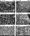
- FIG. 2 is an observation photograph of an iron ore crushed by a pulverizer using a scanning electron microscope (SEM).
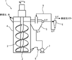
- FIG. 3 is a schematic diagram showing an overall configuration of a tower mill used for producing an iron ore slurry by the method for granulating a sintering raw material of the present invention.
- FIG. 4 is a diagram showing the crushing strength test results of coarse pseudo-particles produced by changing the addition ratio of ultrafine particles.
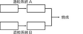
- FIG. 5 is a diagram showing the configuration of the granulation system in the embodiment of the present invention.
- FIG. 6 is a diagram showing the evaluation results of the production rate of sintered ore by the pot sintering test.
- ultrafine particles of iron ore having a particle diameter of 10 ⁇ m or less serve as a binder in granulation.
- the detailed mechanism in which ultrafine particles act as a binder in granulation is as follows.
- the added water serves as a binder that binds the core particles to the adhering powder, and this added water is combined with the core particles during the mixing, stirring, and granulation processes. It enters between the adhering powders and combines them.
- ultrafine particles with a particle size of 10 ⁇ m or less contained in the sintering raw material can move freely with water when suspended in the added water, so the core particles and the adhering powder together with the added water. Get in between. In this way, the ultrafine particles fill the space between the core particles and the adhering powder to form a bridge, thereby increasing the strength of the pseudo particles.
- P-type pseudo particles including the core particles and not including the core particles and having a total amount of 1 mm or less. Is also expected to develop.
- a large amount of ultrafine particles as a binder is required, and when the P-type pseudo particles are charged on a pallet of a sintering machine as compared with normal pseudo particles.
- the present inventors investigated the properties of the pellet feed, and the pellet feed is a fine powder raw material containing 80% by mass or more of particles having a particle size of 250 ⁇ m or less, and almost contains extremely fine particles of 10 ⁇ m or less. I have not found out. This is because the pellet feed improves the iron quality by performing a beneficiation process, specifically, grinding, polishing, washing, flotation, etc. at the mountain base, and ultrafine particles are removed in the process.
- FIG. 1 is a graph showing the particle size distribution of pellet feed (PF.A) and three types of fine iron ore (SF.A, SF.B, SF.C).
- the particle size distribution is measured by the wet sieving method of iron ore specified in JIS M 8716 for particles with a particle size exceeding 250 ⁇ m, and by the wet sieving method for particles having a particle size of 250 ⁇ m or less.
- the fractionated water containing particles of 250 ⁇ m or less was collected, and this fractionated water was measured by a laser diffraction / scattering method defined in JIS R 1629.
- the powdered iron ore has a particle content of more than 10 ⁇ m and not more than 250 ⁇ m with a PF. Although it is smaller than A, it contains about 10 to 15% of ultrafine particles of 10 ⁇ m or less.
- T.A It contains 60% or more of Fe and has high quality.
- Patent Document 3 uses calcium carbonate
- Patent Document 4 uses tailings
- Patent Document 5 uses iron ore crushed using a roller press as binders containing ultrafine particles.
- a step of dispersing the ultrafine particles in water well and suspending them for example, by adding a polymer dispersant. Inferred to be indispensable.
- the present inventors previously prepared a slurry in which ultrafine particles of iron ore are suspended in water (hereinafter also referred to as “iron ore slurry”) as an addition form of ultrafine particles, and the iron ore slurry is sintered. It was judged that the form to be added to the binding raw material is the best one that can obtain the binder effect at low cost.
- the method for producing the iron ore slurry is preferably wet pulverization.
- the pulverization of the iron ore and the suspension of the pulverized iron ore fine particles in water can be performed simultaneously, and the fine particles and water are well mixed without adding a dispersant.
- a separate kneading / kneading step is required to further suspend the ultrafine particles obtained by pulverization in water.
- powder iron ore is pulverized by wet pulverization, and by adding a slurry in which ultrafine particles of iron ore of 10 ⁇ m or less obtained by pulverization are suspended to the sintering raw material, a large amount of pellet feed is blended, It has been found that even when the fine powder ratio of the sintered raw material increases, the air permeability of the packed bed can be secured and the productivity of the sintered ore can be maintained at a low cost.
- FIG. 2 is an observation photograph of the iron ore pulverized by a pulverizer using a scanning electron microscope (SEM).
- A) and (b) are the cases of pulverization by the ball mill described in Patent Document 5, and
- (c) and (d) are pulverized by the roller press described in the same document. Each case is shown as a comparative example.
- E) and (f) of the same figure show the case where it grind
- the respective magnifications are 500 times in FIGS. 2 (a), (c) and (e), and 3000 times in FIGS. 2 (b), (d) and (f).
- FIG. 3 is a schematic diagram showing the overall configuration of a tower mill used for producing an iron ore slurry by the method for granulating a sintering raw material of the present invention.
- the tower mill 1 is a vertical wet pulverizer, and is mainly composed of a pulverization unit, a classification unit, and a circulation unit.
- the pulverizing unit is composed of a cylindrical container 4 provided with a double spiral screw blade 3 on a vertical center shaft 2 that is rotationally driven. In the cylindrical container 4, an iron ball is charged as a pulverizing medium.
- the classification unit includes a water tank 5 connected to the upper side surface of the cylindrical container 4, and a cyclone classification device 6 connected to the water tank 5.
- the circulation section includes a pipe 8 connected from the lower part of the water tank 5 to the lower part of the cylindrical container 4 through the circulation pump 7 and a pipe 9 connected from the lower part of the cyclone classifier 6 to the upper part of the water tank 5.
- the iron ore to be crushed is thrown in from the upper part of the cylindrical container 4 together with water.
- the charged iron ore falls to the lower part of the cylindrical container 4, and moves together with the iron balls in the cylindrical container 4 in the circumferential direction by the rotation of the screw blades 3 accompanying the rotational drive of the vertical center shaft 2.
- the movement of being lifted up and wound upward and the movement of falling downward by its own weight are repeated.
- a shearing force or a compressive force acts between the iron ores or between the iron ore and the iron ball, and the iron ore is crushed (crushed).
- the iron ore In the cylindrical container 4, the iron ore is gradually reduced in size as the pulverization progresses, and when the speed at which the iron ore is wound upward by the rotation of the screw blades 3 is larger than the speed at which the iron ore falls in water due to its own weight, It is suspended in filled water to form a slurry and flows into the water tank 5 on the upper side surface of the cylindrical container 4.
- the iron ore slurry that has flowed into the water tank 5 is roughly classified by the action of gravity.
- the classified coarse iron ore slurry flows into the pipe 8 from the lower part of the water tank 5 as an underflow (see “U / F” in FIG. 3), passes through the circulation pump 7, and flows into the cylindrical container 4. It is returned to the lower part and pulverized again.
- the fine-grain iron ore slurry flows into the cyclone classifier 6 as an overflow (see “O / F” in FIG. 3).
- the iron ore slurry that has flowed into the cyclone classifier 6 is further finely classified by the action of centrifugal force.
- the classified coarse iron ore slurry is returned to the upper part of the water tank 5 through the pipe 9 as an underflow (see “U / F” in FIG. 3), while the fine iron ore slurry Is discharged out of the tower mill 1 as an overflow (see “O / F” in FIG. 3).
- iron ore and water are newly charged into the cylindrical container 4 by the amount of the iron ore slurry discharged out of the system.
- the iron balls as the grinding media are gradually worn, they are appropriately put into the cylindrical container 4 together with the iron ore and replenished.
- the tower mill 1 can continuously supply ultrafine particles of iron ore serving as a binder in granulation as a slurry suspended in water.
- an iron ore slurry is used.
- a slurry tank for temporarily storing the above may be installed.
- the iron ore crushed by the tower mill has a remarkably smaller particle size than the iron ore crushed by the ball mill and roller press.
- the container such as a ball mill which is a typical wet pulverizer other than the tower mill.
- the iron ore crushed by the tower mill has a remarkably small particle size as compared with the case of using other pulverizers.
- the shape of the ultrafine particles is more uneven when entering between the core particles and the adhering powder. It is assumed that the binder effect is high.
- the surface of the iron ore crushed by the tower mill is more uneven than the iron ore crushed by the ball mill. It has a shape.
- FIG. 4 is a diagram showing the crushing strength test results of coarse pseudo-particles produced by changing the addition ratio of ultrafine particles.
- PF.A pellet feed
- FIG. 4 is a diagram showing the crushing strength test results of coarse pseudo-particles produced by changing the addition ratio of ultrafine particles.
- a granulation system B composed of a high speed stirring mixer and a pan pelletizer were used.
- granulation was performed using only the granulation system A, followed by firing.
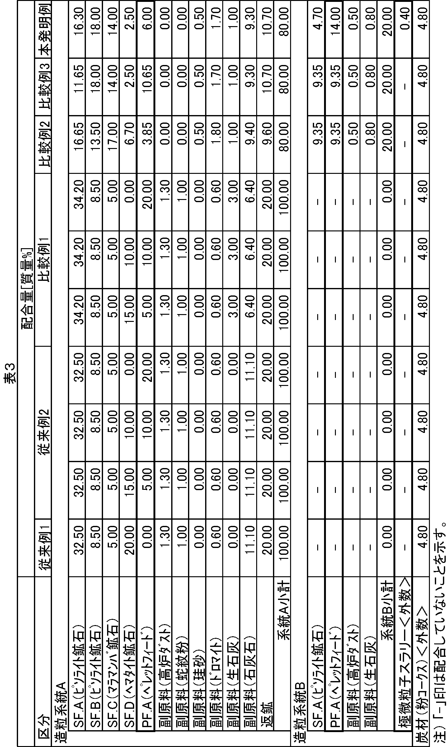
- Comparative Examples 2 and 3 and the present invention example the predetermined sintering raw materials shown in Table 3 were charged into the granulation systems A and B, respectively, and granulated water and in the present invention example iron ore. After the slurry was added and granulated, the sintered raw materials granulated by the granulation systems A and B were merged and fired.
- Iron ore slurry is one of the brands of pisolite ore. A was obtained by wet grinding with a tower mill. Further, in the present invention example, the weight ratio of iron ore to water in the total weight of iron ore slurry is about 50:50, and the ratio of ultrafine particles of 10 ⁇ m or less in the iron ore is 50% by mass. It used for the test.
- the amount of iron ore to be supplied is increased or the amount of water to be supplied together with iron ore is reduced to thereby reduce the iron ore in the slurry. It is possible to increase the concentration of stone particles. However, an increase in the concentration of iron ore particles leads to inhibition of movement of the iron ore particles in water during the crushing process, resulting in a decrease in grinding efficiency. Therefore, in order to perform efficient pulverization, it is necessary to adjust the particle concentration in the slurry to 25% by volume or less, more preferably 20% by volume or less.
- the preferred concentration of iron ore particles in the iron ore slurry is preferably 15% by volume or more and 25% by volume or less.
- the density of iron ore is about 4 g / cm 3 for relatively porous pisolite ore and maramamba ore, and about 5 g / cm 3 for relatively dense hematite ore.
- a concentration range of about 41% by mass or more and about 63% by mass or less is a preferable concentration range.
- the iron ore slurry in the above-described example of the present invention has a SF. Density of about 4 g / cm 3 . Since A was used, the weight ratio of iron ore to water was about 50:50 when pulverized so that the concentration of iron ore particles in the slurry was 20% by volume. Moreover, since the ratio of the ultrafine particles of 10 ⁇ m or less in the iron ore particles in the iron ore slurry has an upper limit on the moisture that can be added during granulation as described above, it is desirable that the ratio be as high as possible.
- the ratio of the ultrafine particles in the iron ore particles in the slurry is increased, the amount of circulating fine particles without being discharged from the pulverizer until the predetermined particle size is reached increases, so that the pulverization efficiency and the pulverization amount are reduced.
- an iron ore slurry in which the ratio of ultrafine particles of 10 ⁇ m or less to the iron ore particles is 50% by mass is used in view of the balance between them.
- the capacity of the pulverizer is sufficiently high, it seems that it is relatively easy to increase the ratio of ultrafine particles while maintaining the pulverization amount.
- the iron ore slurry having a low pulverizer capacity and a low ratio of ultrafine particles can be supplied, it can be said that there is no problem if it is possible to add a predetermined amount of ultrafine particles according to the amount of pellet feed.
- the pseudo-particles of Conventional Examples 1-2, Comparative Examples 1-3, and Example of the Invention produced as described above were placed in a sintering test pot having an inner diameter of 300 mm, a raw material layer thickness of 500 mm, and a weight of about 60 kg. Then, a pot sintering test was conducted. At that time, after igniting with an LPG burner for 1 minute while sucking under a pan pressure of 20 kPa, firing was performed with the pan bottom pressure constant at 9.8 kPa, and suction was performed 3 minutes after the exhaust gas temperature reached the maximum temperature. Stopped, thereby forming a sintered cake and completing the firing. After completion of the sintering test, the sinter production rate was obtained and evaluated by the following method.
- the sintered cake was immediately removed from the sintering test pan and allowed to cool until the temperature of the sintered cake dropped to room temperature. After the cooling was completed, the produced sintered cake was dropped from a height of 2 m four times, and the sieve mesh was sieved with a 5 mm sieve to measure the mass on the sieve to obtain the sintered ore production rate.
- the sintered ore production rate means a value obtained by dividing the mass on the sieve after sieving with a 5 mm sieve by the effective area of the sintering machine and the sintering time. Calculated. At this time, in the case of the pot sintering test, the cross-sectional area of the sintering test pot was used as the effective area of the sintering machine.
- Sinter production rate (ton / m 2 / day) [mass of sintered ore with a particle size of 5 mm or more (ton) / ⁇ effective area of the sintering machine (m 2 ) ⁇ sintering time (min) ⁇ ] ⁇ 60 ⁇ 24 (1)
- FIG. 6 is a diagram showing the evaluation result of the production rate of sintered ore by the pot sintering test.
- the sinter production rate in the case of the conventional example 1 is set as the reference value (100), and the case of the conventional example 2, the comparative examples 1 to 3 and the present invention example with respect to this reference value.
- the sinter production efficiency is shown as a relative value.
- Comparative Example 1 In Comparative Example 1, the blending ratio of high-grade fine iron ore (pellet feed (PF.A)) is set to three conditions of 5.00, 10.00, and 20.00 mass%, and all sintered raw materials are granulated system A. When granulating, 3.00% by mass of quick lime was added as a binder. Thereafter, it was charged into a sintering machine and fired. As shown in FIG. 6, in the case of Comparative Example 1, the relative production rate was increased as a whole by the addition of quicklime, but when 20.00% by mass of pellet feed was blended, quicklime was very 3.00% by mass. The relative production rate did not reach 100 even though a large amount was added.
- pellet feed PF.A
- Comparative Example 2 high-quality fine iron ore (pellet feed (PF.A)) was blended in a total of 13.20% by mass and granulated. That is, granulation system B granulates 20.00% by mass of the total sintered raw material containing 9.35% by mass of pellet feed, and granulation system A holds the remaining 80% of the total sintered raw material containing 3.85% by mass of pellet feed. 0.000 mass% was granulated. At that time, 1.80% by mass of quicklime was added in total. Thereafter, both the granulation system A and the granulation system B were mixed, charged into a sintering machine, and fired. As shown in FIG. 6, from the result of Comparative Example 2, it was confirmed that the relative production rate was maintained equal to that of Conventional Example 1 until 13.20 mass% of the pellet feed was blended.
- PF.A pellet feed
- Comparative Example 3 high-quality fine iron ore (pellet feed (PF.A)) was blended in a total amount of 20.00% by mass and granulated. That is, granulation system B granulates 20.00% by mass of the total sintered raw material containing 9.35% by mass of pellet feed, and granulation system A has the remaining 80% of the total sintered raw material containing 10.65% by mass of pellet feed. 0.000 mass% was granulated. At that time, 1.80% by mass of quicklime was added in total. Thereafter, both the granulation system A and the granulation system B were mixed, charged into a sintering machine, and fired. As shown in FIG. 6, from the result of Comparative Example 3, when the pellet feed was blended up to 20.00% by mass, the granulation system B was used in combination and quick lime was added in a total of 1.80% by mass. It was confirmed that the relative production rate reached only about 84%.
- granulation system B granulates 20.00% by mass of the total sintering raw material including 14.00% by mass of pellet feed (70% by mass in the sintering raw material of granulation system B). The remaining 80.00% by mass of the total sintered raw material containing 6.00% by mass of pellet feed was granulated. At that time, 1.80% by mass of quicklime was added in total. Furthermore, iron ore slurry was added in the granulation system B.
- the iron ore slurry was added to a part of the sintering raw material that contained 50% by mass or more of fine iron ore. At this time, the iron ore slurry was added such that the weight of the iron ore excluding moisture in the iron ore slurry was 0.40% by mass with respect to the total sintered raw material. As described above, since the ratio of the ultrafine particles in the iron ore in the iron ore slurry is 50% by mass, the ultrafine particles of 10 ⁇ m or less per 0.01% by mass of the pellet feed in the blended sintered raw material are 0.01% by mass. % Is added. As shown in FIG. 6, in the case of the example of the present invention, the relative production rate could be maintained equal to that of the conventional example 1 even when the pellet feed was mixed at 20.00% by mass by adding the iron ore slurry.
- the relative feed rate decreased in the case of Comparative Examples 1 to 3, and the pellet feed was reduced to 1.0% by mass even in the range where the blending rate of the pellet feed was higher than 13.20% by mass.
- the iron ore slurry so that the ultrafine particles in the iron ore slurry become 0.01% by mass or more, the production rate of sintered ore is maintained even if the pellet feed is blended up to 20.00% by mass. I knew it was possible.
- a new raw material-based blending ratio in which the amount of so-called new raw material is expressed as 100% by mass, in which the return ore is expressed in the same manner as the carbonaceous material, is often used.
- the blending rate based on the new raw material it can be said that the production rate is maintained even if the pellet feed is blended up to 25% by mass according to the present invention.
- the granulation method of the sintered raw material of the present invention is classified by the action of gravity and centrifugal force, as described above, and a pulverizing part composed of a cylindrical container provided with screw blades on the vertical center shaft to be rotationally driven.
- Iron ore is wet pulverized using a vertical pulverizer having a classification part and a circulation part that circulates the underflow classified in the classification part to the cylindrical container of the pulverization part, and the iron ore slurry formed by wet pulverization is obtained. It is characterized by adding to all or part of the sintering raw material and granulating.
- the sintering raw material has a ratio of particle size of 250 ⁇ m or less of 80% by mass or more and T.I.
- a specific brand of fine iron ore containing 60% by mass or more of Fe (total iron) eg, pellet feed
- the amount of ultrafine particles having a particle size of 10 ⁇ m or less among the iron ore in the iron ore slurry is 0% relative to 1.0% by mass of the fine iron ore. It is preferable to granulate by adding the iron ore slurry so as to be 0.01 mass% or more.
- the sintering raw material is composed of raw materials such as iron ore containing a large amount of pellet feed as a high-quality fine iron ore, auxiliary raw material, return ore, carbonaceous material, etc., and granulation system A, granulation system B, and crushing Divided into three systems.
- the raw material of the granulation system A is granulated by a granulator composed of a drum mixer into pseudo particles.
- the raw material of the granulation system B is mixed and humidity-controlled by a high-speed stirring mixer, and then granulated by a pan pelletizer into coarse pseudo particles.
- the raw material of the crushing system is preliminarily pulverized and mixed with water by wet pulverization using a tower mill, which is a vertical pulverizer, to obtain iron ore slurry.
- the iron ore slurry produced in the crushing system is added to the high-speed stirring mixer together with the raw material of the granulation system B in the granulation of the granulation system B, and becomes a binder when the raw material of the granulation system B is granulated.
- Pseudoparticles produced by granulation of each granulation system are mixed in the process of being charged into the surge hopper, further cut out by the roll feeder, and dropped and deposited on the pallet of the sintering machine. It is mixed in the process of forming the binder filling layer.
- the sintered raw material packed layer thus formed is ignited on the upper surface in an ignition furnace, and while moving from the supply section to the discharge section, air suction from below causes the upper to lower portion of the packed bed. Are fired sequentially.
- the sintered cake after firing is discharged from the discharge portion of the sintering machine, crushed by a crusher, cooled by a cooler, sized by a sieve, and conveyed to a blast furnace.
- wet pulverization is adopted as a technique for producing an iron ore slurry to be added to a sintering raw material, for the following reason.
- the ultrafine particles are required to be well mixed with the added water because of the mechanism of manifestation of the binder effect of the ultrafine particles.
- wet pulverization is an excellent technique that satisfies the requirements because it can pulverize iron ore and suspend the pulverized ultrafine particles in water without using a dispersant or the like.
- a tower mill which is a vertical pulverizer is used for wet pulverization.
- the tower mill can apply a large pulverization force by a composite stirring in the circumferential direction and the vertical direction, and can produce extremely fine particles having a shape with many irregularities that are excellent in binder properties. It is.
- the present invention is extremely useful as a technique that can cope with the depletion of high-grade fine iron ore.
Landscapes
- Engineering & Computer Science (AREA)
- Food Science & Technology (AREA)
- Chemical & Material Sciences (AREA)
- Manufacturing & Machinery (AREA)
- Geology (AREA)
- Geochemistry & Mineralogy (AREA)
- Life Sciences & Earth Sciences (AREA)
- General Life Sciences & Earth Sciences (AREA)
- Materials Engineering (AREA)
- Mechanical Engineering (AREA)
- Metallurgy (AREA)
- Organic Chemistry (AREA)
- Environmental & Geological Engineering (AREA)
- Manufacture And Refinement Of Metals (AREA)
- Separation Of Solids By Using Liquids Or Pneumatic Power (AREA)
Abstract
Description

図2は、粉砕機で粉砕された鉄鉱石の走査電子顕微鏡(SEM)による観察写真である。同図(a)および(b)は、前記特許文献5に記載されているボールミルによって粉砕した場合を、同図(c)および(d)は、同文献に記載されているローラープレスによって粉砕した場合を、それぞれ比較例として示している。同図(e)および(f)は、本発明例として、後述するタワーミルによって粉砕した場合を示している。それぞれの倍率は、図2(a)、(c)および(e)が500倍であり、図2(b)、(d)および(f)が3000倍である。
下記表2に示す通りの割合で、高品位の微粉鉄鉱石としてペレットフィード(PF.A)を配合した焼結原料を4つ準備し、それぞれに対して比率の異なる極微粒子を添加して、直径約10mm以上の粗大擬似粒子(以下、「グリーンボール」とも言う)を製造し、105℃で2時間以上乾燥した後に、各グリーンボールの圧壊応力を測定する圧壊強度試験を行った。その際、極微粒子は、ピソライト鉱石であるSF.Aを10μm以下の極微粒子を60質量%含有する状態となるまで粉砕し、添加した。

下記表3に示す通りに、各種銘柄の鉄鉱石、副原料、返鉱、炭材などを所定の割合で配合し、配合した焼結原料を造粒設備内に装入するとともに、造粒水、および、本発明例では鉄鉱石スラリー(極微粒子スラリー)を添加して造粒し、擬似粒子を製造した。表3において、鉄鉱石スラリーは、表2と表記を合わせるために、炭材は、焼結の実機操業における慣用的な表記法に倣い、それぞれ配合率を外数で表記した。造粒には、図5に示すような、2機のドラムミキサーからなる造粒系統A、および高速撹拌ミキサーとパンペレタイザーとからなる造粒系統Bを用いた。従来例1および2、ならびに比較例1では、造粒系統Aのみを用いて造粒した後、焼成した。一方、比較例2および3、ならびに本発明例では、表3に示す所定の焼結原料を、造粒系統AおよびBのそれぞれに装入し、造粒水、および、本発明例では鉄鉱石スラリーを、添加して造粒した後に、各造粒系統AおよびBで造粒した焼結原料を、合流して、焼成した。
従来例1では、高品位の微粉鉄鉱石(ペレットフィード(PF.A))を0質量%配合し、すなわちペレットフィードを配合することなく、全焼結原料を造粒系統Aで造粒した。その後に焼結機に装入し焼成した。この場合の焼結鉱生産率を基準値(100)とし、以下では、この基準値に対する焼結鉱生産率の比(以下、「相対生産率」という)で比較し、それぞれの場合の焼結鉱生産率を評価した。
従来例2では、高品位の微粉鉄鉱石(ペレットフィード(PF.A))の配合率を5.00、10.00、20.00質量%の3条件とし、全焼結原料を造粒系統Aで造粒した。その後に焼結機に装入し焼成した。従来例2の場合、ペレットフィードの配合率の上昇に伴い、相対生産率は低下した。図6に示すように、特に、ペレットフィードを20.00質量%配合した場合、相対生産率は70を下回っており、ペレットフィードの多量配合によって大幅に生産率が悪化していることが確認できた。
比較例1では、高品位の微粉鉄鉱石(ペレットフィード(PF.A))の配合率を5.00、10.00、20.00質量%の3条件とし、全焼結原料を造粒系統Aで造粒する際に、バインダーとして生石灰を3.00質量%添加した。その後に焼結機に装入し焼成した。図6に示すように、比較例1の場合、生石灰の添加によって相対生産率は全体的に上昇したが、ペレットフィードを20.00質量%配合した場合は、生石灰を3.00質量%と非常に多量に添加したにもかかわらず、相対生産率は100に届かなかった。
比較例2では、高品位の微粉鉄鉱石(ペレットフィード(PF.A))を合計で13.20質量%配合して造粒した。すなわち、造粒系統Bでペレットフィードを9.35質量%含む全焼結原料の20.00質量%を造粒し、造粒系統Aでペレットフィードを3.85質量%含む全焼結原料の残り80.00質量%を造粒した。その際、生石灰を合計で1.80質量%添加した。その後に造粒系統Aおよび造粒系統Bの両者を混合して焼結機に装入し焼成した。図6に示すように、比較例2の結果から、ペレットフィードを13.20質量%配合するまでは、相対生産率を従来例1と同等に維持することが確認できた。
比較例3では、高品位の微粉鉄鉱石(ペレットフィード(PF.A))を合計で20.00質量%配合して造粒した。すなわち、造粒系統Bでペレットフィードを9.35質量%含む全焼結原料の20.00質量%を造粒し、造粒系統Aでペレットフィードを10.65質量%含む全焼結原料の残り80.00質量%を造粒した。その際、生石灰を合計で1.80質量%添加した。その後に造粒系統Aおよび造粒系統Bの両者を混合して焼結機に装入し焼成した。図6に示すように、比較例3の結果から、ペレットフィードを20.00質量%まで配合した場合は、造粒系統Bを併用し、かつ生石灰を合計で1.80質量%添加しても、相対生産率は約84%までしか届かないことが確認できた。
本発明例では、高品位の微粉鉄鉱石(ペレットフィード(PF.A))を合計で20.00%配合して造粒した。すなわち、造粒系統Bでペレットフィードを14.00質量%(造粒系統Bの焼結原料中の70質量%)含む全焼結原料の20.00質量%を造粒し、造粒系統Aでペレットフィードを6.00質量%含む全焼結原料の残り80.00質量%を造粒した。その際、生石灰を合計で1.80質量%添加した。さらに、造粒系統Bで鉄鉱石スラリーを添加した。すなわち、この例では、焼結原料の一部であって微粉鉄鉱石を50質量%以上含む部分に、鉄鉱石スラリーを添加した。このとき、鉄鉱石スラリーは、当該鉄鉱石スラリー中の水分を除く鉄鉱石の重量が、全焼結原料に対し0.40質量%となるように添加した。上述の通り、鉄鉱石スラリーにおける鉄鉱石中の極微粒子の比率は50質量%であるため、配合した焼結原料中のペレットフィード1.0質量%あたり、10μm以下の極微粒子は0.01質量%添加したことになる。図6に示すように、本発明例の場合、鉄鉱石スラリーの添加により、ペレットフィードを20.00質量%配合しても、相対生産率を従来例1と同等に維持することができた。
3:スクリュー翼、 4:円筒容器、 5:水簸槽、
6:サイクロン分級装置、 7:循環ポンプ、 8:配管、
9:配管
Claims (2)
- 鉄鉱石、炭材、副原料および返鉱を配合して焼結原料とし、当該焼結原料を混合、調湿および造粒処理するに際して、
回転駆動する鉛直中心軸にスクリュー翼を備えた円筒容器からなる粉砕部と、重力および遠心力の作用により分級する分級部と、分級部で分級したアンダーフローを粉砕部の円筒容器に循環させる循環部と、を有する竪型粉砕機を用いて鉄鉱石を湿式粉砕し、この湿式粉砕してなる鉄鉱石スラリーを焼結原料の全部または一部に添加して造粒することを特徴とする焼結原料の造粒方法。 - 前記焼結原料は、粒子径250μm以下の比率が80質量%以上であってT.Fe(全鉄)を60質量%以上含有する特定銘柄の微粉鉄鉱石を、少なくとも全焼結原料中に13.20質量%よりも高く20.00質量%以下で含有しており、
この焼結原料の全部、またはこの焼結原料の一部であって当該微粉鉄鉱石を50質量%以上含む部分に、前記鉄鉱石スラリー中の鉄鉱石のうちで粒子径が10μm以下である極微粒子の量が、前記微粉鉄鉱石1.0質量%に対して0.01質量%以上となるように、前記鉄鉱石スラリーを添加して造粒することを特徴とする請求項1に記載の焼結原料の造粒方法。
Priority Applications (3)
| Application Number | Priority Date | Filing Date | Title |
|---|---|---|---|
| CN201280050273.6A CN103857809B (zh) | 2011-10-11 | 2012-09-12 | 烧结原料的造粒方法 |
| JP2013538424A JP5644955B2 (ja) | 2011-10-11 | 2012-09-12 | 焼結原料の造粒方法 |
| KR1020147012395A KR20140079818A (ko) | 2011-10-11 | 2012-09-12 | 소결 원료의 조립 방법 |
Applications Claiming Priority (2)
| Application Number | Priority Date | Filing Date | Title |
|---|---|---|---|
| JP2011224172 | 2011-10-11 | ||
| JP2011-224172 | 2011-10-11 |
Publications (1)
| Publication Number | Publication Date |
|---|---|
| WO2013054471A1 true WO2013054471A1 (ja) | 2013-04-18 |
Family
ID=48081543
Family Applications (1)
| Application Number | Title | Priority Date | Filing Date |
|---|---|---|---|
| PCT/JP2012/005794 Ceased WO2013054471A1 (ja) | 2011-10-11 | 2012-09-12 | 焼結原料の造粒方法 |
Country Status (4)
| Country | Link |
|---|---|
| JP (1) | JP5644955B2 (ja) |
| KR (1) | KR20140079818A (ja) |
| CN (1) | CN103857809B (ja) |
| WO (1) | WO2013054471A1 (ja) |
Cited By (7)
| Publication number | Priority date | Publication date | Assignee | Title |
|---|---|---|---|---|
| JP2016079467A (ja) * | 2014-10-17 | 2016-05-16 | 新日鐵住金株式会社 | 焼結鉱の製造方法 |
| JP2016191122A (ja) * | 2015-03-31 | 2016-11-10 | 新日鐵住金株式会社 | 焼結鉱の製造方法 |
| WO2019087530A1 (ja) * | 2017-10-30 | 2019-05-09 | 住友電気工業株式会社 | 銅ナノ粒子の製造方法 |
| JP2020066766A (ja) * | 2018-10-23 | 2020-04-30 | Jfeスチール株式会社 | 焼結鉱の製造方法 |
| JP2020158889A (ja) * | 2017-03-31 | 2020-10-01 | Jfeスチール株式会社 | 造粒焼結原料の製造方法および焼結鉱の製造方法 |
| KR20210090241A (ko) | 2018-12-26 | 2021-07-19 | 제이에프이 스틸 가부시키가이샤 | 소결광의 제조 방법 |
| CN115127916A (zh) * | 2022-06-29 | 2022-09-30 | 包头钢铁(集团)有限责任公司 | 一种烧结用铁矿石核颗粒强度的评价方法 |
Families Citing this family (4)
| Publication number | Priority date | Publication date | Assignee | Title |
|---|---|---|---|---|
| CN111534685B (zh) * | 2020-05-27 | 2020-12-08 | 中国安全生产科学研究院 | 一种复合硫化物精矿的处理方法 |
| JP7148030B2 (ja) * | 2020-09-30 | 2022-10-05 | Jfeスチール株式会社 | 焼結鉱の製造方法および焼結鉱 |
| CN113019645B (zh) * | 2021-03-22 | 2022-09-09 | 江苏巨胜智能传动科技有限公司 | 一种乌龟养殖用产蛋沙处理装置 |
| TWI879456B (zh) * | 2024-02-27 | 2025-04-01 | 中國鋼鐵股份有限公司 | 含碳燒結球團與其製作方法 |
Citations (3)
| Publication number | Priority date | Publication date | Assignee | Title |
|---|---|---|---|---|
| JPH07256133A (ja) * | 1994-03-25 | 1995-10-09 | Kubota Corp | 摩砕粉砕 |
| JP2008261016A (ja) * | 2007-04-12 | 2008-10-30 | Nippon Steel Corp | 焼結鉱の製造方法 |
| JP2008297585A (ja) * | 2007-05-30 | 2008-12-11 | Nippon Steel Corp | 微粉を含む鉄鉱石原料の造粒方法 |
-
2012
- 2012-09-12 CN CN201280050273.6A patent/CN103857809B/zh active Active
- 2012-09-12 JP JP2013538424A patent/JP5644955B2/ja active Active
- 2012-09-12 KR KR1020147012395A patent/KR20140079818A/ko not_active Ceased
- 2012-09-12 WO PCT/JP2012/005794 patent/WO2013054471A1/ja not_active Ceased
Patent Citations (3)
| Publication number | Priority date | Publication date | Assignee | Title |
|---|---|---|---|---|
| JPH07256133A (ja) * | 1994-03-25 | 1995-10-09 | Kubota Corp | 摩砕粉砕 |
| JP2008261016A (ja) * | 2007-04-12 | 2008-10-30 | Nippon Steel Corp | 焼結鉱の製造方法 |
| JP2008297585A (ja) * | 2007-05-30 | 2008-12-11 | Nippon Steel Corp | 微粉を含む鉄鉱石原料の造粒方法 |
Cited By (8)
| Publication number | Priority date | Publication date | Assignee | Title |
|---|---|---|---|---|
| JP2016079467A (ja) * | 2014-10-17 | 2016-05-16 | 新日鐵住金株式会社 | 焼結鉱の製造方法 |
| JP2016191122A (ja) * | 2015-03-31 | 2016-11-10 | 新日鐵住金株式会社 | 焼結鉱の製造方法 |
| JP2020158889A (ja) * | 2017-03-31 | 2020-10-01 | Jfeスチール株式会社 | 造粒焼結原料の製造方法および焼結鉱の製造方法 |
| WO2019087530A1 (ja) * | 2017-10-30 | 2019-05-09 | 住友電気工業株式会社 | 銅ナノ粒子の製造方法 |
| JP2020066766A (ja) * | 2018-10-23 | 2020-04-30 | Jfeスチール株式会社 | 焼結鉱の製造方法 |
| JP7014127B2 (ja) | 2018-10-23 | 2022-02-01 | Jfeスチール株式会社 | 焼結鉱の製造方法 |
| KR20210090241A (ko) | 2018-12-26 | 2021-07-19 | 제이에프이 스틸 가부시키가이샤 | 소결광의 제조 방법 |
| CN115127916A (zh) * | 2022-06-29 | 2022-09-30 | 包头钢铁(集团)有限责任公司 | 一种烧结用铁矿石核颗粒强度的评价方法 |
Also Published As
| Publication number | Publication date |
|---|---|
| CN103857809B (zh) | 2017-05-17 |
| KR20140079818A (ko) | 2014-06-27 |
| JP5644955B2 (ja) | 2014-12-24 |
| JPWO2013054471A1 (ja) | 2015-03-30 |
| CN103857809A (zh) | 2014-06-11 |
Similar Documents
| Publication | Publication Date | Title |
|---|---|---|
| JP5644955B2 (ja) | 焼結原料の造粒方法 | |
| CN102822355B (zh) | 用于不锈钢熔渣和钢铁制品熔渣的金属回收的制备方法 | |
| WO2014021473A1 (ja) | 金属鉄の製造方法 | |
| JP5569658B2 (ja) | 焼結用造粒原料の製造方法およびその製造装置ならびに高炉用焼結鉱の製造方法 | |
| CN103974776B (zh) | 加工光学纤维废料的方法 | |
| JP6519005B2 (ja) | 焼結鉱の製造方法 | |
| JP6421666B2 (ja) | 焼結鉱の製造方法 | |
| JP5516832B2 (ja) | 焼結鉱用原料粉の調整方法および焼結鉱用原料粉 | |
| JPWO2017094255A1 (ja) | 焼結鉱の製造方法 | |
| JP4156510B2 (ja) | 鉱物粒子を微粉砕する方法および装置 | |
| JP4795484B2 (ja) | 鉄鉱石原料の粉砕方法 | |
| JP5119462B2 (ja) | 焼結原料の事前処理方法及び焼結鉱の製造方法 | |
| JP6337737B2 (ja) | 焼結鉱の製造方法 | |
| JPH03115144A (ja) | 高微粉高炉セメントの製造方法 | |
| JP2014043646A (ja) | 金属鉄の製造方法 | |
| JP6020823B2 (ja) | 焼結用造粒原料の製造方法 | |
| JP5979382B2 (ja) | 焼結用造粒原料の製造方法およびその製造設備 | |
| JP7024647B2 (ja) | 焼結用原料の造粒方法 | |
| JP5928731B2 (ja) | 焼結用造粒原料の製造方法およびその製造装置 | |
| JP7024649B2 (ja) | 焼結用原料の造粒方法 | |
| JPH06212291A (ja) | 焼結鉱製造における焼結原料の前処理方法 | |
| JP7047645B2 (ja) | 焼結鉱の製造方法 | |
| JP6102826B2 (ja) | 焼結鉱の造粒設備 | |
| TWM621815U (zh) | 卜作嵐材料製造系統 | |
| JP5505579B2 (ja) | 焼結鉱用原料粉の調整方法および焼結鉱用原料粉 |
Legal Events
| Date | Code | Title | Description |
|---|---|---|---|
| 121 | Ep: the epo has been informed by wipo that ep was designated in this application |
Ref document number: 12839871 Country of ref document: EP Kind code of ref document: A1 |
|
| ENP | Entry into the national phase |
Ref document number: 2013538424 Country of ref document: JP Kind code of ref document: A |
|
| NENP | Non-entry into the national phase |
Ref country code: DE |
|
| ENP | Entry into the national phase |
Ref document number: 20147012395 Country of ref document: KR Kind code of ref document: A |
|
| 122 | Ep: pct application non-entry in european phase |
Ref document number: 12839871 Country of ref document: EP Kind code of ref document: A1 |