WO2013046920A1 - 変形状態分析方法、樹脂成形体変形改善方法、及び樹脂成形体軽量化方法 - Google Patents
変形状態分析方法、樹脂成形体変形改善方法、及び樹脂成形体軽量化方法 Download PDFInfo
- Publication number
- WO2013046920A1 WO2013046920A1 PCT/JP2012/069740 JP2012069740W WO2013046920A1 WO 2013046920 A1 WO2013046920 A1 WO 2013046920A1 JP 2012069740 W JP2012069740 W JP 2012069740W WO 2013046920 A1 WO2013046920 A1 WO 2013046920A1
- Authority
- WO
- WIPO (PCT)
- Prior art keywords
- deformation
- resin molded
- molded body
- state analysis
- analysis method
- Prior art date
- Legal status (The legal status is an assumption and is not a legal conclusion. Google has not performed a legal analysis and makes no representation as to the accuracy of the status listed.)
- Ceased
Links
Images






Classifications
-
- B—PERFORMING OPERATIONS; TRANSPORTING
- B29—WORKING OF PLASTICS; WORKING OF SUBSTANCES IN A PLASTIC STATE IN GENERAL
- B29C—SHAPING OR JOINING OF PLASTICS; SHAPING OF MATERIAL IN A PLASTIC STATE, NOT OTHERWISE PROVIDED FOR; AFTER-TREATMENT OF THE SHAPED PRODUCTS, e.g. REPAIRING
- B29C45/00—Injection moulding, i.e. forcing the required volume of moulding material through a nozzle into a closed mould; Apparatus therefor
- B29C45/17—Component parts, details or accessories; Auxiliary operations
- B29C45/76—Measuring, controlling or regulating
- B29C45/7693—Measuring, controlling or regulating using rheological models of the material in the mould, e.g. finite elements method
-
- G—PHYSICS
- G06—COMPUTING OR CALCULATING; COUNTING
- G06F—ELECTRIC DIGITAL DATA PROCESSING
- G06F30/00—Computer-aided design [CAD]
-
- G—PHYSICS
- G06—COMPUTING OR CALCULATING; COUNTING
- G06F—ELECTRIC DIGITAL DATA PROCESSING
- G06F30/00—Computer-aided design [CAD]
- G06F30/10—Geometric CAD
-
- G—PHYSICS
- G06—COMPUTING OR CALCULATING; COUNTING
- G06F—ELECTRIC DIGITAL DATA PROCESSING
- G06F30/00—Computer-aided design [CAD]
- G06F30/20—Design optimisation, verification or simulation
- G06F30/23—Design optimisation, verification or simulation using finite element methods [FEM] or finite difference methods [FDM]
-
- G—PHYSICS
- G06—COMPUTING OR CALCULATING; COUNTING
- G06F—ELECTRIC DIGITAL DATA PROCESSING
- G06F2113/00—Details relating to the application field
- G06F2113/22—Moulding
Definitions
- the present invention relates to a deformation state analysis method, a resin molding deformation improvement method, and a resin molding weight reduction method.
- a resin molded body obtained by injection molding or the like of a thermoplastic resin or a resin composition containing a thermoplastic resin is widely used as an industrial product.
- high dimensional accuracy is often required for these resin moldings.
- the main factor that impairs the dimensional accuracy is a defect phenomenon called warpage deformation.
- the CAE analysis is performed under many conditions in order to optimize the product shape, molding conditions, and materials, and according to the function and constraint conditions of the target product.
- a general method is to determine specifications.
- Patent Documents 1 and 2 A method for determining the shape, molding conditions and the like in consideration of such warp deformation is disclosed in Patent Documents 1 and 2 and the like.
- the method described in Patent Document 1 is a method of analyzing a region that affects warp deformation in a resin molded body using a computer, and divides a shape model into at least two or more regions, of which a desired region is selected. Parameters such as wall thickness and length are given, warp deformation analysis is performed, and the sensitivity to the warp deformation amount is obtained from the obtained warp deformation amount, and optimization is performed so that the warp deformation is minimized.
- the plate thickness, the resin-filled gate arrangement, and the gate size are given as parameters, and the parameters are optimized by the optimization calculation so that the warp deformation is minimized.
- JP 2004-268428 A Japanese Patent Laid-Open No. 2005-169766
- the above method requires a great deal of time for parameterizing and optimizing the region division, plate thickness, shape, gate position, and the like.
- setting is easy with a two-dimensional element model (shell element), but it is difficult to create a model with a complicated shape such as a shape with a free-form surface in the two-dimensional element model. .
- the analysis accuracy of warpage deformation itself is often inferior.
- warp deformation analysis itself, it is necessary to repeatedly execute warp deformation analysis in addition to filling analysis, and it is necessary to finely divide the elements in order to increase the analysis accuracy.
- both methods require optimization calculation for a certain area and parameters. However, if the setting area is rough, only a rough shape can be obtained. A lot of labor and time are required, and the calculation time is also great. Thereby, the cost required for calculation when determining the shape is enormous.
- the present invention has been made in order to solve the above-described problems, and the purpose of the present invention is to make a short time when creating and designing a deformation countermeasure plan (for example, a warp deformation countermeasure plan) of a resin molded body.
- An object of the present invention is to provide an analysis method capable of greatly reducing calculation costs and creating a more effective countermeasure plan.
- the inventors of the present invention have made extensive studies to solve the above problems.
- the resin molded body is divided into minute regions and the phase optimization method is used to optimize the objective function under the predetermined constraint conditions and the predetermined constraint conditions.
- the present invention provides the following.
- the resin molded body is divided into minute regions and a phase optimization method is used to optimize the objective function under a predetermined constraint condition and a predetermined constraint condition.
- the contribution rate deriving step is performed based on the correlation between the value calculated by multiplying the deformation amount in each micro region by a coefficient exceeding 1 and the physical properties of the material. Any of (1) to (3) The deformation state analysis method according to claim 1.
- a deformation countermeasure plan for example, a warp deformation countermeasure plan
- a resin molded body design a resin molded body in a short time
- a deformation countermeasure plan and a resin molded body The calculation cost required for the design can be greatly reduced.
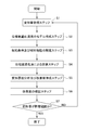
- FIG. 1 is a flowchart showing an example of the deformation state analysis method of the present invention.
- FIG. 2 is a flowchart showing an example of the resin molded body deformation improving method of the present invention.
- FIG. 3 is a flowchart showing an example of the method for reducing the weight of the resin molded body of the present invention.
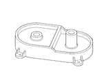
- 4A and 4B are diagrams schematically illustrating a case (case of Reference Example 1) for housing a gear, where FIG. 4A is a front perspective view and FIG. 4B is a rear perspective view.
- FIG. 5 is a diagram schematically illustrating the case of Comparative Example 1.
- FIG. 1 is a flowchart showing an example of the deformation state analysis method of the present invention.
- FIG. 2 is a flowchart showing an example of the resin molded body deformation improving method of the present invention.
- FIG. 3 is a flowchart showing an example of the method for reducing the weight of the resin molded body of the present invention.
- 4A and 4B are
- FIG. 6 is a diagram showing the amount of deformation in the direction perpendicular to the bottom edge surface (Z direction) derived from the injection molding CAE calculation in the case housing the gear.
- (B) is the result of the case of Comparative Example 1.
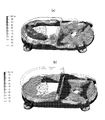
- FIG. 7 is a diagram showing a distribution of contribution ratio indicating the degree to which the deformation of each minute region contributes to the deformation of the resin molded body, (a) is the distribution of the contribution ratio in Reference Example 1, and (b) is It is a distribution of the contribution rate of Comparative Example 1.
- FIG. 8 is a diagram schematically illustrating the case of the first embodiment.
- FIG. 9 is a diagram showing the amount of deformation in the direction perpendicular to the bottom edge surface (Z direction) derived by injection molding CAE calculation in the case of Example 1.
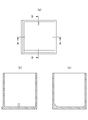
- FIG. FIG. 10 is a diagram schematically showing a cubic container, where (a) is a plan view, (b) is an AA cross-sectional view, and (c) is a BB cross-sectional view.
- FIG. 11 is a diagram illustrating a tendency of the deformation amount, which is a constraint condition, when the contribution rate distribution is derived.
- FIG. 12 is a diagram showing a distribution of contribution ratio indicating the degree to which deformation of each minute region contributes to deformation of the resin molding, (a) is a distribution of contribution ratio in a plan view, and (b) is a diagram of FIG. 10 is a distribution of contribution ratio in the AA cross section of FIG. 10, and FIG. 10C is a distribution of contribution ratio in the BB section of FIG.
- the deformation state analysis method of the present embodiment includes a deformation amount acquisition step (S1), a phase optimization method model creation step (S2), a constraint condition and material physical property setting step (S3). ), And a calculation step (S4) by the phase optimization method.
- the constraint condition used in the calculation step (S4) by the phase optimization method is a tendency of the deformation amount of the resin molded body (a distribution representing the tendency of deformation).
- the tendency of the deformation amount refers to the tendency of deformation, and other than the deformation amount, for example, a value obtained by multiplying the deformation amount by a coefficient may be used.
- the deformation amount is derived in order to acquire the deformation amount tendency.
- the method for deriving the deformation amount is not particularly limited, and the deformation amount derived by CAE analysis or the like can be used as the deformation amount. Further, a deformation amount derived by actual measurement may be used.
- the tendency of the deformation amount is expressed by using a value obtained by multiplying the deformation amount by a coefficient exceeding 1, the tendency of the deformation becomes clearer. For this reason, even if it is a tendency to include a minute change, the minute change can be taken into consideration, and the accuracy of analysis is increased.
- the deformation of the resin molded body in the present invention is a case where an external force is applied to the resin molded body to deform the resin molded body, or a case where the resin molded body is deformed by contraction and expansion of the resin contained in the resin molded body ( Any of warp deformation and the like is included.
- the analysis of the deformation state may be performed on the entire resin molded body, or may be performed on only a part thereof. In the case of performing only a part, a tendency of the deformation amount may be derived for the part and the following steps may be performed.
- Model creation step for phase optimization method (S2) In the model creation step (S2) for the phase optimization method, the resin molded body is divided into minute regions, and a model necessary for performing the phase optimization method is created. For example, first, using a CAD interface or the like, the shape of the resin molding is taken into a personal computer or the like, or the shape of the resin molding is created by a CAD system, and the modeling range is set. Next, the resin molded body is divided into a plurality of regions by performing element division such as a finite element method with an element division preprocessor or the like, and a model for analysis is created.
- element division such as a finite element method with an element division preprocessor or the like
- the shape of the element can be selected from tetrahedral primary element, secondary element, hexahedral primary element, secondary element, and the like.
- the deformation amount is obtained by analysis in the deformation amount acquisition step (S1), it is necessary to select an element according to the specifications of the finite element method software, the specifications of the computer system to be calculated, and the calculation cost. Also, if the number of element divisions is not sufficiently fine, high calculation accuracy cannot be obtained. On the other hand, in the finite element model used for the phase optimization, since it is necessary to repeat the calculation a plurality of times, the number of elements is required to be small. Therefore, a preferable division number is appropriately adopted in consideration of calculation accuracy, calculation time, and the like.
- a finite element model has been described as an example of a model for calculation in the phase optimization method.
- CAE analysis such as finite difference analysis or meshless analysis. It can also be used.
- the specific threshold value of the contribution rate is not particularly limited, and can be set as appropriate according to the accuracy of analysis to be obtained. For example, if the threshold value is set too high, it may be determined that the threshold value is below the threshold value even though it actually contributes to the deformation, so that it is difficult to analyze the deformation state with high accuracy. On the other hand, if the threshold value is too low, it may be determined that the threshold value is not less than the threshold value even though it actually contributes little to deformation. In this case as well, it is difficult to accurately analyze the deformation state. . It should be noted that what threshold value can be used to separate what contributes to actual deformation and what does not contribute depends on the type of material constituting the resin molding.
- the physical properties necessary for calculating the contribution ratio are physical properties related to the deformation of the resin molded body, such as Poisson's ratio and elastic modulus. Note that physical properties other than Poisson's ratio and elastic modulus may be considered.
- the deformation distribution or the deformation tendency reproduces the deformation state of the resin molded body, the contribution rate described later becomes a constant value regardless of the deformation amount obtained by the analysis. For this reason, even if the elastic modulus is different from the actual value, a more accurate deformation countermeasure can be performed.
- the used material has anisotropy, distribution, etc. in the elastic modulus due to the influence of higher order structure and filler, it is desirable to give it to the physical property value in consideration thereof.
- the specific calculation method of the phase optimization is based on a conventionally known mathematical programming method, a homogenization design method (HDM: Homogenization Design Method), a density method (Density Approach), a genetic algorithm, An annealing method, a cellular automaton method, etc. are used.
- HDM Homogenization Design Method
- Density Approach Density Approach
- a genetic algorithm An annealing method, a cellular automaton method, etc.
- OPTI STRUCT manufactured by Altair
- OPTISHAPE manufactured by Kuinto Corporation
- TOSCA manufactured by FE-design.
- the threshold value of the contribution rate is used as a constraint condition.
- how much the threshold value is satisfied and how much the threshold value is not satisfied are also evaluated. By performing such an evaluation, it is possible to accurately grasp the contribution rate, and it becomes possible to analyze the deformation state more accurately.
- the above calculation is used to evaluate how much the threshold is satisfied and how much the threshold is not satisfied, it is possible to confirm the contribution rate in each minute region regardless of the threshold value.
- the threshold value can be arbitrarily selected.
- the distribution of the contribution ratio in the resin molded body can be derived by deriving the contribution ratio of each minute region.
- the contribution rate represents the degree to which the deformation of each minute region contributes to the deformation of the resin molded body.
- the region where the contribution ratio is large is a portion that greatly affects the deformation of the resin molded body, and the region where the contribution ratio is small is a portion that does not affect the deformation of the resin molded body. Therefore, by deriving the distribution of the contribution ratio, it is possible to easily distinguish a region that is largely involved in the deformation of the resin molded body and a region that is not significantly involved in the deformation of the resin molded body.
- the threshold setting is appropriate, it is confirmed that the area below the threshold by the above calculation is an area that is not significantly involved in the deformation of the resin molded product.
- the region that is equal to or greater than the threshold value by the above calculation is a region that is greatly involved in the deformation of the resin molded body. Therefore, even in this case, it is possible to obtain the distribution of the region related to the deformation of the resin molded body and the region not involved in the resin molded body.
- the threshold value is less than the threshold value, it may be evaluated by calculation how much the threshold value is not satisfied, or only when the threshold value is exceeded, how much the threshold value is exceeded may be evaluated by calculation. In this way, it is also possible to evaluate the contribution rate in detail only for a part.
- the method of improving the deformation of the resin molded body of the present invention is to make the resin molded body difficult to deform by changing the shape of the resin molded body when the resin molded body is deformed by external force, expansion of the resin molded body such as warping deformation, In the case of deformation due to shrinkage, the shape of the resin molded body can be changed to make it difficult to deform.
- the method for improving deformation of the resin molded body of the present invention uses the analysis result obtained by the above-described deformation state analysis method, the deformation can be improved efficiently. Specifically, by using the analysis result, it is possible to easily determine a portion that needs improvement for improvement in the resin molded body.
- the resin molded body deformation improving method of the present embodiment includes a deformation amount acquisition step (S1), a phase optimization method model creation step (S2), a constraint condition and a material physical property setting step ( S3), a phase optimization method calculation step (S4), a deformation cause analysis and improvement plan creation step (S5), and an improvement plan verification step (S6).
- the deformation amount acquisition step (S1), the phase optimization method model creation step (S2), the constraint condition and material property setting step (S3), and the phase optimization method calculation step (S4) are modified. Since it is the same as that described in the state analysis method, description regarding these steps is omitted.
- deformation cause analysis and improvement plan creation step (S5) In the deformation cause analysis, a part that causes deformation is identified from the analysis result obtained by the above-described deformation state analysis method. As described above, the analysis results show the parts that are greatly involved in the deformation. Therefore, the area that is highly involved (usually a set of multiple micro areas) is identified as the area that may cause the deformation. To do. Subsequently, a location that causes deformation is estimated from the identified region in consideration of the thickness, shape, and the like of the resin molded body in the region.
- the “part greatly involved in deformation” is generally a range in which the contribution ratio derived by the deformation state analysis method includes a minute region having an average value or more.
- the shape that suppresses deformation can be easily determined by improving the region contributing to deformation.
- the shape of the range including a minute region whose contribution ratio in the resin molded body is equal to or higher than the average is changed.
- the shape to be changed may be determined based on the common general technical knowledge, or may be determined based on the relationship between the tendency of deformation of the resin molded body examined in the past and improvement measures.
- the mode of change of the shape of the range including the minute region where the contribution ratio in the resin molded body exceeds the average, and the deformation of the resin molded body that changes depending on the mode of the change It is preferable to derive a plurality of relationships with the aspect in advance and determine what shape to change based on the plurality of relationships. This is because there is a high possibility of improvement.
- the improvement plan verification step it is verified whether or not the improvement plan created in the deformation cause analysis and improvement plan creation step (S5) is an appropriate improvement plan.
- analysis such as CAE analysis and confirm the effect of improvement by analysis, or by actually molding and confirm the effect of suppressing deformation of the resin molded body
- a verification step can be performed.
- the deformation improving method of the present invention is terminated.
- the range of the allowable deformation amount varies depending on the shape, application, etc. of the resin molded body, a desired range is appropriately set according to the situation.
- the process returns to the model creation step (S2) for the phase optimization method, and the model creation step (S2) for the phase optimization method ) To repeat the improvement plan verification step (S6). If the amount of deformation falls within an acceptable range, the improvement method of the present invention ends.
- the method for reducing the weight of a resin molded body according to the present invention is a method for reducing the weight by removing an excess portion from the resin molded body without deforming the resin molded body.
- the method for reducing the weight of the resin molded body of the present invention uses the analysis result obtained by the above-described deformation state analysis method, it is possible to greatly suppress the occurrence of deformation in the resin molded body due to the weight reduction. Specifically, since the region contributing to deformation in the resin molded body is clear by using the above analysis result, the distinction between the region in which the resin molded body is deformed and the region in which the deformation does not occur is clear. Therefore, it is possible to reduce the possibility of deformation of the resin molded body due to weight reduction.
- the resin molded body weight reduction method of the present embodiment includes a deformation amount acquisition step (S1), a model creation step for phase optimization method (S2), a constraint condition and a material physical property setting step ( S3), a phase optimization method calculation step (S4), a weight reduction plan creation step (S7), and a weight reduction verification step (S8).
- the deformation amount acquisition step (S1), the phase optimization method model creation step (S2), the constraint condition and material property setting step (S3), and the phase optimization method calculation step (S4) are modified. Since it is the same as that described in the state analysis method, description regarding these steps is omitted.
- Weight reduction verification step (S8) In the weight reduction verification step, it is verified whether or not the weight reduction plan created in the weight reduction plan creation step (S7) is an appropriate weight reduction plan. For example, a method for confirming the occurrence of deformation due to weight reduction by performing analysis such as CAE analysis on a resin molded body that has been partially reduced due to a weight reduction plan, or by actually molding and resin molding
- the weight reduction verification step (S8) can be performed by a method of confirming whether or not the body is deformed.
- the resin molded body weight reduction method of the present invention is terminated.
- the range of the allowable deformation amount varies depending on the shape, application, etc. of the resin molded body, a desired range is appropriately set according to the situation.
- the process returns to the model creation step (S2) for the phase optimization method, and the model creation step (S2) for the phase optimization method ) To repeat the improvement plan verification step (S8). If the amount of deformation falls within an allowable range, the weight reduction method of the present invention is finished.
- FIG. 4 schematically shows a case (reference example 1) for housing the gear.
- FIG. 4A is a top perspective view
- FIG. 4B is a bottom perspective view.
- the annular edge surface the blacked-out portion in the drawing
- the case is a resin molded body
- the thermoplastic resin constituting the resin molded body has an elastic modulus of 2500 MPa and a Poisson's ratio of 0.35.
- the model for the phase optimization method was created according to a general countermeasure against warp deformation. Using this model, the deformation amount shown in FIG. 6 is used as a constraint condition, and the contribution rate indicating the degree to which the deformation of each minute region contributes to the deformation of the resin molded product is used as a constraint condition.
- the objective function was optimized to be The distribution of the contribution rate was derived by displaying the portion where the contribution rate was 50% or more in increments of 5%. The derivation result is shown in FIG.
- the distribution of the contribution rate it is possible to distinguish the region contributing to deformation and the region not contributing to deformation in the case of Reference Example 1. Moreover, it was confirmed from the distribution of the contribution ratio of the case of the comparative example 1 that the rib for suppressing warpage deformation is not effective for suppressing warpage deformation.
- Example 1 in which a triangular rib was added to this portion was manufactured. Moreover, in the case of Example 1, the rib was provided so that the edge of an upper surface might be enclosed.
- FIG. 8 schematically shows the case of Example 1.
- the warp amount of the case of Reference Example 1, the warp amount of the case of Comparative Example 1, and the warp amount of the case of Example 1 were derived from (Z direction warp deformation maximum value)-(Z direction warp deformation minimum value). .
- the volume of the case of the reference example 1, the volume of the case of the comparative example 1, and the volume of the case of Example 1 were calculated
- Example 1 the amount of warpage deformation is reduced to the same extent as in Comparative Example 1 compared to Reference Example 1. Further, the volume is reduced as compared with Comparative Example 1. From the results of the table, according to the method of the present invention, it is possible to design an effective countermeasure against warping deformation while reducing the volume (or reducing the increase in volume).
- FIG. 10A is a plan view
- FIG. 10B is an AA sectional view
- FIG. 10C is a BB sectional view.
- the side of the box is curved inward (for example, examination of the influence of mold temperature control design on warpage deformation, Takahashi, Sekino, Kobayashi, molding '96 , P145 to P146 (1996). Therefore, in the container shown in FIG. 10, in order to suppress the above deformation, the bottom surface and one side surface and the boundary inside the container are formed in an arc shape so that the bottom surface protrudes from the boundary between the bottom surface and the predetermined bottom surface outside the container. And a triangular rib that exists across the bottom and side surfaces inside the container.
- the deformation amount shown in FIG. 10 As a condition, the objective function was optimized so as to minimize the decrease in the rigidity of the molded resin.
- the distribution of the contribution rate was derived by displaying the portion where the contribution rate was 50% or more in increments of 3% or 4%. The derivation result is shown in FIG.
- the contribution ratio of the outer rib and the inner arc-shaped portion is 50% or less. On the other hand, the contribution ratio is 90% or more in the triangular rib portion.
- a cube-shaped molded body in which only the outer ribs were formed, a cube-shaped molded body in which only the arc-shaped bottom was formed, and a cube-shaped molded body in which only the triangular ribs were formed were actually manufactured, and the degree of deformation was confirmed. As expected, the deformation was suppressed only in the cubic shaped body in which the triangular ribs were formed.
Landscapes
- Engineering & Computer Science (AREA)
- Physics & Mathematics (AREA)
- Theoretical Computer Science (AREA)
- Geometry (AREA)
- General Physics & Mathematics (AREA)
- Computer Hardware Design (AREA)
- Evolutionary Computation (AREA)
- General Engineering & Computer Science (AREA)
- Manufacturing & Machinery (AREA)
- Mechanical Engineering (AREA)
- Computational Mathematics (AREA)
- Mathematical Analysis (AREA)
- Mathematical Optimization (AREA)
- Pure & Applied Mathematics (AREA)
- Injection Moulding Of Plastics Or The Like (AREA)
- Architecture (AREA)
- Software Systems (AREA)
Abstract
樹脂成形体の変形対策案(例えば、反り変形対策案)を作成、設計する際に、短時間かつ計算コストが大幅に削減され、より効果的な対策案を作成することが可能となる解析方法を提供する。 変形する樹脂成形体について、樹脂成形体を微小領域に分割し位相最適化法を用い、所定の拘束条件、所定の制約条件の下で目的関数の最適化を行うことで樹脂成形体の変形状態を分析する変形状態分析方法であって、所定の拘束条件を、樹脂成形体の変形量の傾向とし、所定の制約条件を、各微小領域の変形が樹脂成形体の変形に寄与する程度を表す寄与率とし、目的関数の最適化では、樹脂成形体の剛性の低下を最小化するように最適化を行う。
Description
本発明は、変形状態分析方法、樹脂成形体変形改善方法、及び樹脂成形体軽量化方法に関する。
熱可塑性樹脂や熱可塑性樹脂を含む樹脂組成物を射出成形等することにより得られる樹脂成形体は、工業製品として広く使用されている。ところで、これらの樹脂成形体には高い寸法精度が要求される場合が多い。この寸法精度を損ねる主な要因は、そり変形と呼ばれる不良現象である。
そり変形を予測する方法としては、コンピュータを利用した射出成形のCAE(コンピュータ援用エンジニアリング)を用いる方法がある。このCAEは、様々な樹脂成形体の設計現場に導入されており、樹脂成形体の設計の期間短縮や試作費用の低減の目的に使用されている。例えば、製品形状、成形条件、材料物性値を設定し、反り解析を行うことにより、リブの追加等の形状変更や、ゲート位置、射出速度等の成形条件の変更、材料の変更を、コンピュータ上で検討することができる。
樹脂成形体を試作する前の設計段階においては、製品形状、成形条件、材料を最適化するために、多くの条件で上記CAEによる解析を行い、目的とする製品の機能、制約条件に応じた仕様を決定していく方法が一般的である。
このようなそり変形を考慮して形状、成形条件等を決定するための方法が、特許文献1、2等に開示されている。特許文献1に記載の方法とは、コンピュータを用いて、樹脂成形体における反り変形に影響する領域を分析する方法であり、形状モデルを少なくとも2つ以上の領域に区分し、そのうち所望する領域に肉厚、長さ等のパラメータを与え、それぞれそり変形解析を行い、得られたそり変形量から、そり変形量に対する感度を求め、そり変形が最小になるように最適化するものである。
特許文献2に記載の方法も同様に、板厚、樹脂充填ゲート配置、ゲートサイズをパラメータとして与え、最適化計算により反り変形が最小になるように、パラメータを最適化するものである。
しかしながら、上記のような方法は、領域分割、板厚、形状、ゲート位置等をパラメータ化して最適化することに多大な時間を必要とする。板厚のみの変更の場合、2次元要素モデル(シェル要素)であれば設定が容易であるが、2次元要素モデルでは自由曲面を有する形状等、複雑な形状の場合はモデル作成が困難である。さらに、2次元要素モデルでは、反り変形自体の解析精度が劣る場合が多い。通常の反り変形解析自体は、充填解析に加え、反り変形解析を繰り返し実行する必要があり、解析精度を高めるために要素分割を細かくする必要があるため、解析実行時間も多大となる。さらに、いずれの方法とも、ある程度の領域、パラメータに最適化計算を必要とするが、設定領域が粗い場合には、大まかな形状しか得られず、設定領域を細かくする場合には分割するために多大な労力、時間を必要となり、計算時間も多大となる。それにより、形状を決定する際の計算に要するコストが膨大となっている。
また、反り解析によって製品の反り状態を予測できても、反り低減に有効な形状変更等の対策を製品のどの領域に、どの様に行えば有効であるかという判断は、技術者の勘と経験に頼っているのが実状である。上記特許文献1、2に記載の方法においても、パラメータを設定するべき領域である反りの原因となる領域がある程度予測できれば、計算コスト削減及び設計時間短縮が可能になるが、現状ではそれを判断する合理的な手段、方法がない。
本発明は、以上のような課題を解決するためになされたものであり、その目的は、樹脂成形体の変形対策案(例えば、反り変形対策案)を作成、設計する際に、短時間かつ計算コストが大幅に削減され、より効果的な対策案を作成することが可能となる解析方法を提供することにある。
本発明者らは、上記課題を解決するために鋭意研究を重ねた。その結果、変形する樹脂成形体について、樹脂成形体を微小領域に分割し位相最適化法を用い、所定の拘束条件、所定の制約条件の下で目的関数の最適化を行うことで樹脂成形体の変形状態を分析する変形状態分析方法であって、所定の拘束条件を、樹脂成形体の変形量の傾向とし、所定の制約条件を、各微小領域の変形が樹脂成形体の変形に寄与する程度を表す寄与率とし、目的関数の最適化では、樹脂成形体の剛性の低下を最小化するように最適化が行われることで、上記課題を解決できることを見出し、本発明を完成するに至った。より具体的には、本発明は以下のものを提供する。
(1) 変形する樹脂成形体について、樹脂成形体を微小領域に分割し位相最適化法を用い、所定の拘束条件、所定の制約条件の下で目的関数の最適化を行うことで樹脂成形体の変形状態を分析する変形状態分析方法であって、前記所定の拘束条件は、樹脂成形体の変形量の傾向であり、前記所定の制約条件は、各微小領域の変形が樹脂成形体の変形に寄与する程度を表す寄与率であり、前記目的関数の最適化は、樹脂成形体の剛性の低下を最小化するように最適化を行う変形状態分析方法。
(2) 前記変形量は、有限要素法を用いて導出された(1)に記載の変形状態分析方法。
(3) 前記変形量は、実測値である(1)に記載の変形状態分析方法。
(4) 各微小領域での変形量に1を超える係数を乗じて算出した値と前記材料の物性との相関関係に基づいて、前記寄与率導出工程を行う(1)から(3)のいずれかに記載の変形状態分析方法。
(5) (1)から(4)のいずれかに記載の変形状態分析方法で導出した寄与率が、平均値以上の微小領域を含む範囲の形状を変更することにより、樹脂成形体の変形を抑制する樹脂成形体変形改善方法。
(6) 樹脂成形体における前記寄与率が平均以上の微小領域を含む範囲の形状の変更の態様と、前記変更の態様により変化する樹脂成形体の変形の態様と、の関係を予め複数導出し、前記複数の関係に基づいて、寄与率が平均値以上の微小領域を含む範囲の形状を変更する(5)に記載の樹脂成形体変形改善方法。
(7) (1)から(4)のいずれかに記載の変形状態分析方法で導出した寄与率が、平均値以上の微小領域を含む範囲の形状を変更する形状変更工程と、前記形状変更工程後に、樹脂成形体を製造し変形状態を確認する確認工程と、樹脂成形体の変形量が所定の値以上の場合には、前記変形量が所定の値以下になるまで、前記形状の変更の態様を変えて、前記形状変更工程と前記確認工程とを繰り返し行う樹脂成形体変形改善方法。
(8) (1)から(4)のいずれかに記載の変形状態分析方法で導出した寄与率が、平均値以下の微小領域を含む範囲の少なくとも一部を削減することにより、樹脂成形体を軽量化する樹脂成形体軽量化方法。
本発明によれば、樹脂成形体の変形対策案(例えば、反り変形対策案)の作成や樹脂成形体の設計を、短時間で行うことができ、かつ変形対策案の作成や樹脂成形体の設計に必要となる計算コストを大幅に削減することができる。
以下、本発明の実施形態について説明する。なお、本発明は以下の実施形態に限定されない。
<変形状態分析方法>
本発明の変形状態分析方法の一例について、図1のフローチャートを用いて説明する。図1のフローチャートに示すように、本実施形態の変形状態分析方法は、変形量取得ステップ(S1)、位相最適化法用のモデル作成ステップ(S2)、制約条件及び材料物性の設定ステップ(S3)、位相最適化法による計算ステップ(S4)を備える。
本発明の変形状態分析方法の一例について、図1のフローチャートを用いて説明する。図1のフローチャートに示すように、本実施形態の変形状態分析方法は、変形量取得ステップ(S1)、位相最適化法用のモデル作成ステップ(S2)、制約条件及び材料物性の設定ステップ(S3)、位相最適化法による計算ステップ(S4)を備える。
[変形量取得ステップ(S1)]
本実施形態では、位相最適化法による計算ステップ(S4)に用いる拘束条件が、樹脂成形体の変形量の傾向(変形の傾向を表す分布)である。変形量の傾向とは、変形の傾向を指し、変形量以外には例えば変形量に係数を乗じたもの等が挙げられる。本ステップでは、変形量の傾向を取得するために変形量を導出する。
本実施形態では、位相最適化法による計算ステップ(S4)に用いる拘束条件が、樹脂成形体の変形量の傾向(変形の傾向を表す分布)である。変形量の傾向とは、変形の傾向を指し、変形量以外には例えば変形量に係数を乗じたもの等が挙げられる。本ステップでは、変形量の傾向を取得するために変形量を導出する。
変形量の導出方法は特に限定されず、変形量はCAE解析等によって導出した変形量を用いることができる。また、実測により導出した変形量を用いてもよい。
変形の分布あるいは変形の傾向が、樹脂成形体の変形状態を再現していれば、後述する寄与率は、解析により導出される変形量によらず一定の値になる。このため、CAE解析による変形量絶対値の解析精度に関らず、より正確な分析が可能になる。
特に変形量に1を超える係数を乗じた値を用いて、変形量の傾向を表せば変形の傾向がより明瞭になる。このため、微小な変化を含む傾向であっても、この微小な変化を考慮することができ、分析の精度が高まる。
なお、本発明における樹脂成形体の変形とは、樹脂成形体に外力が加えられて樹脂成形体が変形する場合、樹脂成形体に含まれる樹脂の収縮及び膨張により樹脂成形体が変形する場合(反り変形等)のいずれも含まれる。
また、変形状態の分析は、樹脂成形体全体に対して行ってもよいし、一部にのみ行ってもよい。一部にのみ行う場合は、その一部について変形量の傾向を導出して、以下のステップを行えばよい。
[位相最適化法用のモデル作成ステップ(S2)]
位相最適化法用のモデル作成ステップ(S2)は、樹脂成形体を微小な領域に分割して、位相最適化法の実施に必要なモデルを作成する。例えば、先ず、CADインターフェース等を利用して、樹脂成形体の形状をパソコン等に取り込む、あるいはCADシステムにより樹脂成形体の形状を作成し、モデル化範囲を設定する。次いで、要素分割プリプロセッサ等で有限要素法等の要素分割を行うことで樹脂成形体を複数の領域に分割して、解析用のモデルを作成する。
位相最適化法用のモデル作成ステップ(S2)は、樹脂成形体を微小な領域に分割して、位相最適化法の実施に必要なモデルを作成する。例えば、先ず、CADインターフェース等を利用して、樹脂成形体の形状をパソコン等に取り込む、あるいはCADシステムにより樹脂成形体の形状を作成し、モデル化範囲を設定する。次いで、要素分割プリプロセッサ等で有限要素法等の要素分割を行うことで樹脂成形体を複数の領域に分割して、解析用のモデルを作成する。
要素の形状は、四面体1次要素、2次要素、六面体1次要素、2次要素等が選択可能である。変形量取得ステップ(S1)で変形量を解析により求める場合は、有限要素法ソフトの仕様、計算するコンピュータシステムの仕様、計算コストに応じて要素を選択する必要がある。また、要素分割数が十分細かくないと、高い計算精度が得られない。一方、位相最適化に用いる有限要素モデルにおいては、計算を複数回繰り返す必要があるため、要素数は少ないことが求められる。したがって、計算精度、計算時間等を考慮して、適宜好ましい分割数を採用する。
位相最適化法での計算のためのモデルとして、有限要素モデルを例に説明したが、有限差分解析あるいはメッシュレス解析等他のタイプのCAE解析の結果を、上記のようなモデルを得るために用いることもできる。
[制約条件及び材料物性の設定ステップ(S3)]
制約条件及び材料物性の設定ステップ(S3)では、各微小領域の変形が樹脂成形体の変形に寄与する程度を表す寄与率(本実施形態の制約条件である)について、具体的な閾値の値を設定する。また、位相最適化法による計算ステップ(S4)での寄与率の計算に用いる物性値を設定する。なお、ここで寄与率とは[1-(制約条件を満たしつつ削除可能な体積/元の形状の体積)]×100(%)である。
制約条件及び材料物性の設定ステップ(S3)では、各微小領域の変形が樹脂成形体の変形に寄与する程度を表す寄与率(本実施形態の制約条件である)について、具体的な閾値の値を設定する。また、位相最適化法による計算ステップ(S4)での寄与率の計算に用いる物性値を設定する。なお、ここで寄与率とは[1-(制約条件を満たしつつ削除可能な体積/元の形状の体積)]×100(%)である。
寄与率の具体的な閾値は、特に限定されず、求める分析の精度等に応じて適宜設定することができる。例えば、閾値を高く設定し過ぎると、実際には変形に寄与しているにも拘わらず閾値以下と判断される可能性があるため、変形の状態を精度良く分析することが難しくなる。一方、閾値の値が低すぎると、実際には変形にほとんど寄与していないにも拘わらず閾値以上と判断される可能性があるため、この場合も変形の状態を精度良く分析することが難しい。なお、どの程度の閾値であれば、実際の変形に寄与するものと、寄与しないものとを分けることができるかについては、樹脂成形体を構成する材料の種類等によっても異なる。
また、寄与率の計算に必要な物性とは、樹脂成形体の変形に関する物性であり、ポアソン比、弾性率である。なお、ポアソン比、弾性率以外の物性を考慮してもよい。
なお、上述の通り、変形の分布あるいは変形の傾向が、樹脂成形体の変形状態を再現していれば、後述する寄与率は解析により得られる変形量によらず一定の値になる。このため、弾性率が実際の値と異なっていても、より正確な変形対策案を行うことが可能である。しかし、用いた材料が高次組織、充填材の影響により弾性率に異方性、分布等がある場合、それを考慮して物性値に与えることが望ましい。
[位相最適化法による計算ステップ(S4)]
位相最適化法による計算ステップでは、変形量取得ステップ(S1)で取得した変形量の傾向を、位相最適化法用のモデル作成ステップ(S2)で作成したモデルに適用し、上記で設定した物性パラメータを用い、寄与率の閾値を制約条件として、目的関数が最小になるように最適化を行う。本発明においては、樹脂成形体の剛性の低下を最小化するように最適化が行われる。
位相最適化法による計算ステップでは、変形量取得ステップ(S1)で取得した変形量の傾向を、位相最適化法用のモデル作成ステップ(S2)で作成したモデルに適用し、上記で設定した物性パラメータを用い、寄与率の閾値を制約条件として、目的関数が最小になるように最適化を行う。本発明においては、樹脂成形体の剛性の低下を最小化するように最適化が行われる。
上記において、位相最適化の具体的な計算手法については従来公知の数理計画法(Mathematical Programming)に基づく、均質化設計法(HDM:Homogenization Design Method)、密度法(Density Approach)、遺伝的アルゴリズム、焼きなまし法、セルオートマトン法等が用いられている。これらは、Altair社製OPTI STRUCT、株式会社くいんと製OPTISHAPE、FE-design社製TOSCA等市販のソフトにて実施可能である。
本実施形態においては、寄与率の閾値を制約条件とするが、閾値を満たすか否かの評価に加えて、閾値をどの程度満たすか、や閾値をどの程度満たさないかについても評価する。このような評価を行うことで、寄与率を的確に把握することができ、より正確な変形状態の分析が可能になる。また、閾値をどの程度満たし、どの程度満たさないかを上記の計算で評価する場合には、閾値をどのような値に設定しても、各微小領域での寄与率を確認することができるため、閾値の値は任意に選択することができる。
上記のようにして、各微小領域の寄与率を導出することで、樹脂成形体における、上記寄与率の分布を導出することができる。上記の通り、寄与率とは、各微小領域の変形が樹脂成形体の変形に寄与する程度を表す。寄与率が大きい領域は、樹脂成形体の変形に大きな影響を与える部分であり、寄与率が小さい領域は、樹脂成形体の変形に影響を与えない部分である。したがって、寄与率の分布を導出することで、樹脂成形体の変形に大きく関与する領域と樹脂成形体の変形にあまり関与しない領域とを容易に識別することができる。
閾値未満、閾値以上のみを評価する場合であっても、閾値の設定が適切であれば、上記の計算により閾値以下とされる領域は樹脂成形体の変形にあまり関与しない領域であることが確認でき、また、上記の計算により閾値以上とされる領域は樹脂成形体の変形に大きく関与する領域であることが確認できる。したがって、この場合であっても、樹脂成形体における、樹脂成形体の変形に関与する領域と、関与しない領域との分布を求めることができる。
また、閾値未満の場合についてのみ、閾値をどの程度満たしていないかを計算により評価してもよいし、閾値を以上の場合についてのみ、閾値をどの程度超えるかを計算により評価してもよい。このように一部についてのみ寄与率を詳細に評価することも可能である。
<樹脂成形体変形改善方法>
本発明の樹脂成形体の変形を改善する方法は、樹脂成形体が外力により変形させられる場合に樹脂成形体の形状を変更して変形し難くしたり、反り変形等の樹脂成形体の膨張、収縮により変形する場合に樹脂成形体の形状を変更して変形し難くしたりすることができる。
本発明の樹脂成形体の変形を改善する方法は、樹脂成形体が外力により変形させられる場合に樹脂成形体の形状を変更して変形し難くしたり、反り変形等の樹脂成形体の膨張、収縮により変形する場合に樹脂成形体の形状を変更して変形し難くしたりすることができる。
特に本発明の樹脂成形体の変形を改善する方法は、上記の変形状態分析方法による分析結果を用いるため、変形の改善を効率よく行うことができる。具体的には、上記分析結果を用いることで、樹脂成形体における改善のために改良が必要となる部分を容易に判断することができる。
以下、本発明の樹脂成形体変形改善方法の一例について、図2に示すフローチャートを用いて説明する。図2のフローチャートに示す通り、本実施形態の樹脂成形体変形改善方法は、変形量取得ステップ(S1)、位相最適化法用のモデル作成ステップ(S2)、制約条件及び材料物性の設定ステップ(S3)、位相最適化法による計算ステップ(S4)、変形原因分析及び改善案作成ステップ(S5)、改善案の検証ステップ(S6)を備える。
ここで、変形量取得ステップ(S1)、位相最適化法用のモデル作成ステップ(S2)、制約条件及び材料物性の設定ステップ(S3)、位相最適化法による計算ステップ(S4)については、変形状態分析方法で説明したものと同様であるため、これらのステップに関する説明は省略する。
[変形原因分析及び改善案作成ステップ(S5)]
変形原因分析では、上記の変形状態分析方法で得られた分析結果から、変形の原因となる部分を特定する。上記の通り、分析結果には変形に大きく関与する部分が示されているため、関与の大きい領域(通常、複数の微小領域の集合である)を変形の原因となる可能性のある領域として特定する。続いて、特定した領域の中から、その領域での樹脂成形体の厚み、形状等を考慮して、変形の原因となる箇所を推測する。「変形に大きく関与する部分」とは、一般的に、変形状態分析方法で導出した寄与率が、平均値以上の微小領域を含む範囲である。
変形原因分析では、上記の変形状態分析方法で得られた分析結果から、変形の原因となる部分を特定する。上記の通り、分析結果には変形に大きく関与する部分が示されているため、関与の大きい領域(通常、複数の微小領域の集合である)を変形の原因となる可能性のある領域として特定する。続いて、特定した領域の中から、その領域での樹脂成形体の厚み、形状等を考慮して、変形の原因となる箇所を推測する。「変形に大きく関与する部分」とは、一般的に、変形状態分析方法で導出した寄与率が、平均値以上の微小領域を含む範囲である。
変形の原因となる箇所を推測した後、変形を抑えるための改善方法について検討する。本発明では、変形に寄与する領域を容易に見極めることができるため、変形に寄与する領域を改良することで、容易に変形を抑える形状を決定することができる。本実施形態では、樹脂成形体における寄与率が平均以上の微小領域を含む範囲の形状の変更を行う。
どのような形状に変更するかは、技術常識に基づいて決定してもよいし、過去に検討した樹脂成形体の変形の傾向と改善策との関係に基づいて決定してもよい。特に、過去に検討した樹脂成形体の変形に対する改善において、樹脂成形体における寄与率が平均以上の微小領域を含む範囲の形状の変更の態様と、その変更の態様により変化する樹脂成形体の変形の態様との関係を予め複数導出しておき、これら複数の関係に基づいて、どのような形状に変更するかを決定することが好ましい。改善される可能性が高いからである。
[改善案の検証ステップ(S6)]
改善案の検証ステップでは、変形原因分析及び改善案作成ステップ(S5)で作成した改善案が適切な改善案であるか否かについて検証する。例えば、改良を施した樹脂成形体について、CAE解析等の解析を行い、解析により改善の効果を確認する方法、また、実際に成形を行い、樹脂成形体の変形抑制の効果を確認する方法で検証ステップを行うことができる。
改善案の検証ステップでは、変形原因分析及び改善案作成ステップ(S5)で作成した改善案が適切な改善案であるか否かについて検証する。例えば、改良を施した樹脂成形体について、CAE解析等の解析を行い、解析により改善の効果を確認する方法、また、実際に成形を行い、樹脂成形体の変形抑制の効果を確認する方法で検証ステップを行うことができる。
検証を行った結果、樹脂成形体の変形量が許容できる範囲である場合には、本発明の変形改善方法を終了する。ここで、許容可能な変形量の範囲は、樹脂成形体の形状、用途等によって異なるため、状況に応じて所望の範囲が適宜設定される。
一方、検証を行った結果、樹脂成形体の変形量が許容できる範囲を超える場合には、位相最適化法用のモデル作成ステップ(S2)に戻り、位相最適化法用のモデル作成ステップ(S2)~改善案の検証ステップ(S6)を繰り返す。変形量が許容できる範囲になれば、本発明の改善方法は終了する。
<樹脂成形体軽量化方法>
本発明の樹脂成形体の軽量化方法は、樹脂成形体を変形させずに樹脂成形体から余分な部分を取り除き軽量化する方法である。
本発明の樹脂成形体の軽量化方法は、樹脂成形体を変形させずに樹脂成形体から余分な部分を取り除き軽量化する方法である。
特に本発明の樹脂成形体の軽量化方法は、上記の変形状態分析方法による分析結果を用いるため、軽量化により樹脂成形体に変形が発生することを大幅に抑えることができる。具体的には、上記分析結果を用いることで、樹脂成形体における変形に寄与する領域が明瞭であるため、取り除くことで樹脂成形体に変形が生じる領域と変形が生じない領域との区別が明確であるため、軽量化により樹脂成形体に変形が生じる可能性を低くすることができる。
以下、本発明の樹脂成形体を軽量化する方法の一例について、図3に示すフローチャートを用いて説明する。図3のフローチャートに示す通り、本実施形態の樹脂成形体軽量化方法は、変形量取得ステップ(S1)、位相最適化法用のモデル作成ステップ(S2)、制約条件及び材料物性の設定ステップ(S3)、位相最適化法による計算ステップ(S4)、軽量化案作成ステップ(S7)、軽量化検証ステップ(S8)を備える。
ここで、変形量取得ステップ(S1)、位相最適化法用のモデル作成ステップ(S2)、制約条件及び材料物性の設定ステップ(S3)、位相最適化法による計算ステップ(S4)については、変形状態分析方法で説明したものと同様であるため、これらのステップに関する説明は省略する。
[軽量化案作成ステップ(S7)]
上記の変形状態分析方法で得られた分析結果から、樹脂成形体の変形に関与の大きい領域(通常、複数の微小領域の集合である)、関与の小さい領域を精度良く区別することができる。これを利用して、樹脂成形体の変形に関与の小さい領域の少なくとも一部を削減する軽量化案を作成する。ここで、変形に大きく関与する領域とは、一般的に、変形状態分析方法で導出した寄与率が、平均値以上の微小領域を含む範囲である。
上記の変形状態分析方法で得られた分析結果から、樹脂成形体の変形に関与の大きい領域(通常、複数の微小領域の集合である)、関与の小さい領域を精度良く区別することができる。これを利用して、樹脂成形体の変形に関与の小さい領域の少なくとも一部を削減する軽量化案を作成する。ここで、変形に大きく関与する領域とは、一般的に、変形状態分析方法で導出した寄与率が、平均値以上の微小領域を含む範囲である。
[軽量化検証ステップ(S8)]
軽量化検証ステップでは、軽量化案作成ステップ(S7)で作成した軽量化案が適切な軽量化案であるか否かについて検証する。例えば、軽量化案により、一部を削減した樹脂成形体について、CAE解析等の解析を行い、解析により軽量化による変形の発生の有無を確認する方法、また、実際に成形を行い、樹脂成形体に変形が発生するか否かを確認する方法で軽量化検証ステップ(S8)を行うことができる。
軽量化検証ステップでは、軽量化案作成ステップ(S7)で作成した軽量化案が適切な軽量化案であるか否かについて検証する。例えば、軽量化案により、一部を削減した樹脂成形体について、CAE解析等の解析を行い、解析により軽量化による変形の発生の有無を確認する方法、また、実際に成形を行い、樹脂成形体に変形が発生するか否かを確認する方法で軽量化検証ステップ(S8)を行うことができる。
検証を行った結果、樹脂成形体の変形量が許容できる範囲である場合には、本発明の樹脂成形体軽量化方法を終了する。ここで、許容可能な変形量の範囲は、樹脂成形体の形状、用途等によって異なるため、状況に応じて所望の範囲が適宜設定される。
一方、検証を行った結果、樹脂成形体の変形量が許容できる範囲を超える場合には、位相最適化法用のモデル作成ステップ(S2)に戻り、位相最適化法用のモデル作成ステップ(S2)~改善案の検証ステップ(S8)を繰り返す。変形量が許容できる範囲になれば、本発明の軽量化方法は終了する。
以下、実施例及び比較例を示し、本発明を具体的に説明するが、本発明はこれらの実施例に限定されるものではない。
図4には、ギアを収納するケース(参考例1)を模式的に示す。図4(a)は上面側の斜視図であり、図4(b)は底面側の斜視図である。参考例1のケースにおいては、図4(b)に示す環状の縁面(図中の黒く塗りつぶされた部分)が平面であることが求められる。ここで、上記ケースは樹脂成形体であり、樹脂成形体を構成する熱可塑性樹脂の弾性率が2500MPa、ポアソン比が0.35である。
図4に示すギアケースに反り変形が生じ、図4(b)で示す部分の平面性が損なわれることを防ぐ目的で、上面の縁にリブが形成されたケース(比較例1のケース)を作製した。比較例1のケースの上面側の斜視図を図5に示した。
参考例1のケース、比較例1のケースについて、射出成形CAE計算により、上記縁面に垂直な方向をZ方向とし、Z方向のそり変形を求めた。結果を図6に示した。
参考例1のケース、比較例1のケースについて、位相最適化法用のモデルは一般的なそり変形対策に準じて作成した。このモデルを用い、図6に記載の変形量を拘束条件とし、各微小領域の変形が樹脂成形体の変形に寄与する程度を表す寄与率を制約条件として、樹脂成形体の剛性の低下を最小化するように目的関数を最適化した。寄与率が50%以上の部分を5%きざみで表示する方法で、寄与率の分布を導出した。導出結果を図7に示した。
この寄与率の分布によれば、参考例1のケースにおける変形に寄与する領域と変形に寄与しない領域とを区別することができる。また、比較例1のケースの寄与率の分布から、反り変形抑制のためのリブが反り変形の抑制に効果的では無いことが確認された。
先ず、図7の寄与率の分布によれば、ケースの表面に存在する段差の付け根の両端は局所的に寄与率が高い。そこで、この部分に三角リブを追加した実施例1のケースを製造した。また、実施例1のケースでは、上面の縁を囲うようにリブを設けた。図8には実施例1のケースを模式的に示した。
図8の改善案の形状について、射出成形CAE計算により、上記縁面に垂直な方向をZ方向とし、Z方向のそり変形を求めた。結果を図9に示した。図9から明らかなように、反り変形が改善されていることが確認された。
また、参考例1のケースの反り量、比較例1のケースの反り量、実施例1のケースの反り量を、(Z方向そり変形最大値)-(Z方向そり変形最小値)から導出した。また、参考例1のケースの体積、比較例1のケースの体積、実施例1のケースの体積は、CADソフトに組み込まれた機能を用い求めた。反り量及び体積の結果を表1に示した。

実施例1については、参考例1に比べ比較例1と同程度にそり変形量が低減している。また、比較例1に比べ体積が減少している。表の結果から本発明の方法によれば、体積を削減しつつ(又は体積の増加量が小さくなるように)、効果的なそり変形対策案を設計することができる。
続いて、図10に示す立方体状の容器について評価を行った。図10(a)は平面図であり、(b)はAA断面図であり、(c)はBB断面図である。
立方体状の容器の場合には、箱の側面が内側に向かい湾曲することが知られている(例えば、そり変形に与える金型温調設計の影響に関する検討 高橋、関野、小林、成形加工‘96 ,P145~P146 1996)。そこで、図10に示す容器では、上記の変形を抑制するために、容器内部の底面と一の側面と境界を円弧状にし、容器の外側における底面と所定の底面との境界から底面が突き出すように延びるリブを形成し、容器内部の底面と側面とにまたがって存在する三角リブを形成する。
図10に示す容器に関し、上記の文献等の記載に基づいて、図11に記載の変形量を拘束条件とし、各微小領域の変形が樹脂成形体の変形に寄与する程度を表す寄与率を制約条件として、樹脂成形体の剛性の低下を最小化するように目的関数を最適化した。寄与率が50%以上の部分を3%又は4%きざみで表示する方法で、寄与率の分布を導出した。導出結果を図12に示した。
外側のリブ、内側の円弧形状部分はいずれも寄与率が50%以下である。一方、三角リブの部分では寄与率が90%以上である。上記外側のリブのみ形成した立方体状成形体、上記円弧状の底のみ形成した立方体状成形体、上記三角リブのみ形成した立方体状成形体を実際に製造し、変形具合を確認した。上記の予想通り、三角リブを形成した立方体状成形体のみ変形が抑制されていた。
Claims (8)
- 変形する樹脂成形体について、樹脂成形体を微小領域に分割し位相最適化法を用い、所定の拘束条件、所定の制約条件の下で目的関数の最適化を行うことで樹脂成形体の変形状態を分析する変形状態分析方法であって、
前記所定の拘束条件は、樹脂成形体の変形量の傾向であり、
前記所定の制約条件は、各微小領域の変形が樹脂成形体の変形に寄与する程度を表す寄与率であり
前記目的関数の最適化は、樹脂成形体の剛性の低下を最小化するように最適化を行う変形状態分析方法。 - 前記変形量は、有限要素法を用いて導出された請求項1に記載の変形状態分析方法。
- 前記変形量は、実測値である請求項1に記載の変形状態分析方法。
- 各微小領域での変形量に1を超える係数を乗じて算出した値を、前記樹脂成形体の変形量として用いる請求項1から3のいずれかに記載の変形状態分析方法。
- 請求項1から4のいずれかに記載の変形状態分析方法で導出した寄与率が、平均値以上の微小領域を含む範囲の形状を変更することにより、樹脂成形体の変形を抑制する樹脂成形体変形改善方法。
- 樹脂成形体における前記寄与率が平均以上の微小領域を含む範囲の形状の変更の態様と、前記変更の態様により変化する樹脂成形体の変形の態様と、の関係を予め複数導出し、
前記複数の関係に基づいて、寄与率が平均値以上の微小領域を含む範囲の形状を変更する請求項5に記載の樹脂成形体変形改善方法。 - 請求項1から4のいずれかに記載の変形状態分析方法で導出した寄与率が、平均値以上の微小領域を含む範囲の形状を変更する形状変更工程と、
前記形状変更工程後に、樹脂成形体を製造し変形状態を確認する確認工程と、
樹脂成形体の変形量が所定の値以上の場合には、前記変形量が所定の値以下になるまで、前記形状の変更の態様を変えて、前記形状変更工程と前記確認工程とを繰り返し行う樹脂成形体変形改善方法。 - 請求項1から4のいずれかに記載の変形状態分析方法で導出した寄与率が、平均値以下の微小領域を含む範囲の少なくとも一部を削減することにより、樹脂成形体を軽量化する樹脂成形体軽量化方法。
Priority Applications (2)
| Application Number | Priority Date | Filing Date | Title |
|---|---|---|---|
| US14/348,478 US9659117B2 (en) | 2011-09-29 | 2012-08-02 | Deformation state analysis method, resin molded article deformation improvement method, and resin molded article weight reduction method |
| CN201280047377.1A CN103826825B (zh) | 2011-09-29 | 2012-08-02 | 变形状态分析方法、树脂成形体变形改善方法、以及树脂成形体轻量化方法 |
Applications Claiming Priority (2)
| Application Number | Priority Date | Filing Date | Title |
|---|---|---|---|
| JP2011214664A JP5800655B2 (ja) | 2011-09-29 | 2011-09-29 | 樹脂成形体変形改善方法及び樹脂成形体軽量化方法 |
| JP2011-214664 | 2011-09-29 |
Publications (1)
| Publication Number | Publication Date |
|---|---|
| WO2013046920A1 true WO2013046920A1 (ja) | 2013-04-04 |
Family
ID=47994973
Family Applications (1)
| Application Number | Title | Priority Date | Filing Date |
|---|---|---|---|
| PCT/JP2012/069740 Ceased WO2013046920A1 (ja) | 2011-09-29 | 2012-08-02 | 変形状態分析方法、樹脂成形体変形改善方法、及び樹脂成形体軽量化方法 |
Country Status (4)
| Country | Link |
|---|---|
| US (1) | US9659117B2 (ja) |
| JP (1) | JP5800655B2 (ja) |
| CN (1) | CN103826825B (ja) |
| WO (1) | WO2013046920A1 (ja) |
Cited By (3)
| Publication number | Priority date | Publication date | Assignee | Title |
|---|---|---|---|---|
| JP2017161981A (ja) * | 2016-03-07 | 2017-09-14 | 株式会社東芝 | 解析装置、解析方法および解析プログラム |
| WO2021200058A1 (ja) * | 2020-03-31 | 2021-10-07 | 東レエンジニアリング株式会社 | 設計支援装置および設計支援方法 |
| JP2022068606A (ja) * | 2020-10-22 | 2022-05-10 | 富士通株式会社 | 最適化装置、最適化方法、及び最適化プログラム |
Families Citing this family (4)
| Publication number | Priority date | Publication date | Assignee | Title |
|---|---|---|---|---|
| CN103568163B (zh) * | 2013-11-06 | 2015-11-18 | 常熟市汽车饰件股份有限公司 | 一种注塑产品快速反变形修模方法 |
| CN108920780B (zh) * | 2018-06-14 | 2022-11-22 | 湖南文理学院 | 一种基于应变能的车身结构优化设计方法 |
| CN109543287B (zh) * | 2018-11-20 | 2023-04-07 | 深能南京能源控股有限公司 | 基于遗传算法的风电机组基础尺寸优化方法 |
| JP7335212B2 (ja) * | 2020-09-02 | 2023-08-29 | 株式会社豊田自動織機 | 押出樹脂シートの中間加工方法 |
Citations (4)
| Publication number | Priority date | Publication date | Assignee | Title |
|---|---|---|---|---|
| JP2004167686A (ja) * | 2002-11-15 | 2004-06-17 | Kanto Auto Works Ltd | 樹脂成形品の剛性構造決定方法 |
| JP2004268428A (ja) * | 2003-03-10 | 2004-09-30 | Toray Ind Inc | そり影響領域分析方法およびその装置ならびにプログラムおよびその記憶媒体ならびに射出成形品の製造方法 |
| JP2007004238A (ja) * | 2005-06-21 | 2007-01-11 | Canon Software Inc | 解析支援装置および解析支援方法およびプログラム |
| JP2008021217A (ja) * | 2006-07-14 | 2008-01-31 | Kanto Auto Works Ltd | 樹脂成形品の剛性最適化解析方法並びに剛性最適化解析プログラム及びその記録媒体 |
Family Cites Families (8)
| Publication number | Priority date | Publication date | Assignee | Title |
|---|---|---|---|---|
| JPH10138310A (ja) * | 1996-11-08 | 1998-05-26 | Honda Motor Co Ltd | 射出成形機の最適成形条件決定方法 |
| US7465416B2 (en) * | 2003-03-31 | 2008-12-16 | Sumitomo Chemical Company, Limited | Method for designing a mold, method for producing an injection molding, program and injection molding device |
| JP4052468B2 (ja) * | 2003-11-17 | 2008-02-27 | 関東自動車工業株式会社 | 樹脂成形品の剛性構造決定方法 |
| JP2005169766A (ja) | 2003-12-10 | 2005-06-30 | Toyota Motor Corp | 金型最適化装置、金型最適化プログラム、及び、金型最適化制御プログラム |
| JP4403277B2 (ja) * | 2006-02-28 | 2010-01-27 | 国立大学法人 北海道大学 | 凸多面体に対する重心座標を用いた自由形状変形システム |
| JP4803809B2 (ja) * | 2006-08-01 | 2011-10-26 | 本田技研工業株式会社 | 構造最適化方法 |
| WO2008032443A1 (en) * | 2006-09-12 | 2008-03-20 | Mitsubishi Engineering-Plastics Corporation | Panel-shaped molded product |
| JP4592104B2 (ja) | 2007-05-07 | 2010-12-01 | 関東自動車工業株式会社 | 樹脂成形品の剛性構造決定装置 |
-
2011
- 2011-09-29 JP JP2011214664A patent/JP5800655B2/ja active Active
-
2012
- 2012-08-02 WO PCT/JP2012/069740 patent/WO2013046920A1/ja not_active Ceased
- 2012-08-02 US US14/348,478 patent/US9659117B2/en active Active
- 2012-08-02 CN CN201280047377.1A patent/CN103826825B/zh active Active
Patent Citations (4)
| Publication number | Priority date | Publication date | Assignee | Title |
|---|---|---|---|---|
| JP2004167686A (ja) * | 2002-11-15 | 2004-06-17 | Kanto Auto Works Ltd | 樹脂成形品の剛性構造決定方法 |
| JP2004268428A (ja) * | 2003-03-10 | 2004-09-30 | Toray Ind Inc | そり影響領域分析方法およびその装置ならびにプログラムおよびその記憶媒体ならびに射出成形品の製造方法 |
| JP2007004238A (ja) * | 2005-06-21 | 2007-01-11 | Canon Software Inc | 解析支援装置および解析支援方法およびプログラム |
| JP2008021217A (ja) * | 2006-07-14 | 2008-01-31 | Kanto Auto Works Ltd | 樹脂成形品の剛性最適化解析方法並びに剛性最適化解析プログラム及びその記録媒体 |
Cited By (6)
| Publication number | Priority date | Publication date | Assignee | Title |
|---|---|---|---|---|
| JP2017161981A (ja) * | 2016-03-07 | 2017-09-14 | 株式会社東芝 | 解析装置、解析方法および解析プログラム |
| WO2021200058A1 (ja) * | 2020-03-31 | 2021-10-07 | 東レエンジニアリング株式会社 | 設計支援装置および設計支援方法 |
| JP2021162978A (ja) * | 2020-03-31 | 2021-10-11 | 東レエンジニアリング株式会社 | 設計支援装置および設計支援方法 |
| JP7407642B2 (ja) | 2020-03-31 | 2024-01-04 | 東レエンジニアリング株式会社 | 設計支援装置および設計支援方法 |
| JP2022068606A (ja) * | 2020-10-22 | 2022-05-10 | 富士通株式会社 | 最適化装置、最適化方法、及び最適化プログラム |
| JP7556260B2 (ja) | 2020-10-22 | 2024-09-26 | 富士通株式会社 | 最適化装置、最適化方法、及び最適化プログラム |
Also Published As
| Publication number | Publication date |
|---|---|
| JP2013071444A (ja) | 2013-04-22 |
| CN103826825B (zh) | 2015-08-26 |
| US9659117B2 (en) | 2017-05-23 |
| US20150005916A1 (en) | 2015-01-01 |
| JP5800655B2 (ja) | 2015-10-28 |
| CN103826825A (zh) | 2014-05-28 |
Similar Documents
| Publication | Publication Date | Title |
|---|---|---|
| JP5800655B2 (ja) | 樹脂成形体変形改善方法及び樹脂成形体軽量化方法 | |
| CN101807220B (zh) | 用于评估铸件设计的可制造性的系统 | |
| Stupnytskyy | Features of functionally-oriented engineering technologies in concurrent environment | |
| Lin et al. | Automatic generation of mold-piece regions and parting curves for complex CAD models in multi-piece mold design | |
| JP2011014060A (ja) | 数値解析方法および数値解析装置 | |
| JP5241310B2 (ja) | 成形品の変形形状の予測方法とその装置、変形形状の予測プログラムとその記憶媒体 | |
| Chakraborty et al. | Automatic determination of parting directions, parting lines and surfaces for two-piece permanent molds | |
| JP5911466B2 (ja) | プレス成形におけるドローモデル判定方法及びシステム | |
| JP6949415B2 (ja) | 金型cadモデルデータ作成装置及び金型cadモデルデータ作成方法 | |
| JP5349859B2 (ja) | 成形品形状の予測方法、成形品の製造方法、成形品形状の予測プログラムとその記憶媒体 | |
| JP4544556B2 (ja) | 射出成形品製造パラメータ決定支援システム | |
| CN107530934B (zh) | 各向异性树脂成型体的构造解析方法 | |
| JP5899004B2 (ja) | 成形品そり変形予測装置、成形品そり変形予測方法及び成形品そり変形予測プログラム | |
| JP5889077B2 (ja) | 成形品収縮変形予測装置、成形品収縮変形予測方法及び成形品収縮変形予測プログラム | |
| JP6804801B2 (ja) | 樹脂成形品のそり変形防止設計方法、プログラム、記録媒体、および樹脂成形品のそり変形防止設計装置 | |
| JP2008200859A (ja) | そり変形解析方法およびそのプログラムならびにそり変形解析装置 | |
| WO2023195419A1 (ja) | 成形不良予測方法、成形不良低減方法、成形不良予測プログラム及び成形不良低減プログラム | |
| US11741270B2 (en) | Computer aided design (CAD)-based foam part generation for seat designs | |
| CN107134012B (zh) | 基于布尔运算与逆向工程精确修改原cad模型的方法 | |
| JP7579117B2 (ja) | 樹脂成形品解析方法、プログラム、記録媒体および樹脂成形品解析装置 | |
| JP2007268763A (ja) | 樹脂成形品の取付位置特定方法及びその製造方法 | |
| JP2007253495A (ja) | 成形条件の設定方法、プログラムおよび射出成形機 | |
| JP2004276311A (ja) | 樹脂成形品のボイド不良予測方法、樹脂成形品のボイド不良予測ソフトウェアおよび記録媒体 | |
| JP7440438B2 (ja) | 公差解析システム | |
| JP2024146769A (ja) | シミュレーション装置、シミュレーションシステム、シミュレーション方法、シミュレーションプログラム、及び記録媒体 |
Legal Events
| Date | Code | Title | Description |
|---|---|---|---|
| 121 | Ep: the epo has been informed by wipo that ep was designated in this application |
Ref document number: 12835465 Country of ref document: EP Kind code of ref document: A1 |
|
| NENP | Non-entry into the national phase |
Ref country code: DE |
|
| WWE | Wipo information: entry into national phase |
Ref document number: 14348478 Country of ref document: US |
|
| 122 | Ep: pct application non-entry in european phase |
Ref document number: 12835465 Country of ref document: EP Kind code of ref document: A1 |