WO2013046893A1 - モータ制御装置 - Google Patents
モータ制御装置 Download PDFInfo
- Publication number
- WO2013046893A1 WO2013046893A1 PCT/JP2012/068851 JP2012068851W WO2013046893A1 WO 2013046893 A1 WO2013046893 A1 WO 2013046893A1 JP 2012068851 W JP2012068851 W JP 2012068851W WO 2013046893 A1 WO2013046893 A1 WO 2013046893A1
- Authority
- WO
- WIPO (PCT)
- Prior art keywords
- motor
- control device
- battery
- current
- mode
- Prior art date
- Legal status (The legal status is an assumption and is not a legal conclusion. Google has not performed a legal analysis and makes no representation as to the accuracy of the status listed.)
- Ceased
Links
Images




Classifications
-
- H—ELECTRICITY
- H02—GENERATION; CONVERSION OR DISTRIBUTION OF ELECTRIC POWER
- H02P—CONTROL OR REGULATION OF ELECTRIC MOTORS, ELECTRIC GENERATORS OR DYNAMO-ELECTRIC CONVERTERS; CONTROLLING TRANSFORMERS, REACTORS OR CHOKE COILS
- H02P27/00—Arrangements or methods for the control of AC motors characterised by the kind of supply voltage
- H02P27/04—Arrangements or methods for the control of AC motors characterised by the kind of supply voltage using variable-frequency supply voltage, e.g. inverter or converter supply voltage
- H02P27/06—Arrangements or methods for the control of AC motors characterised by the kind of supply voltage using variable-frequency supply voltage, e.g. inverter or converter supply voltage using DC to AC converters or inverters
-
- B—PERFORMING OPERATIONS; TRANSPORTING
- B60—VEHICLES IN GENERAL
- B60L—PROPULSION OF ELECTRICALLY-PROPELLED VEHICLES; SUPPLYING ELECTRIC POWER FOR AUXILIARY EQUIPMENT OF ELECTRICALLY-PROPELLED VEHICLES; ELECTRODYNAMIC BRAKE SYSTEMS FOR VEHICLES IN GENERAL; MAGNETIC SUSPENSION OR LEVITATION FOR VEHICLES; MONITORING OPERATING VARIABLES OF ELECTRICALLY-PROPELLED VEHICLES; ELECTRIC SAFETY DEVICES FOR ELECTRICALLY-PROPELLED VEHICLES
- B60L15/00—Methods, circuits, or devices for controlling the traction-motor speed of electrically-propelled vehicles
- B60L15/20—Methods, circuits, or devices for controlling the traction-motor speed of electrically-propelled vehicles for control of the vehicle or its driving motor to achieve a desired performance, e.g. speed, torque, programmed variation of speed
- B60L15/2045—Methods, circuits, or devices for controlling the traction-motor speed of electrically-propelled vehicles for control of the vehicle or its driving motor to achieve a desired performance, e.g. speed, torque, programmed variation of speed for optimising the use of energy
-
- B—PERFORMING OPERATIONS; TRANSPORTING
- B60—VEHICLES IN GENERAL
- B60L—PROPULSION OF ELECTRICALLY-PROPELLED VEHICLES; SUPPLYING ELECTRIC POWER FOR AUXILIARY EQUIPMENT OF ELECTRICALLY-PROPELLED VEHICLES; ELECTRODYNAMIC BRAKE SYSTEMS FOR VEHICLES IN GENERAL; MAGNETIC SUSPENSION OR LEVITATION FOR VEHICLES; MONITORING OPERATING VARIABLES OF ELECTRICALLY-PROPELLED VEHICLES; ELECTRIC SAFETY DEVICES FOR ELECTRICALLY-PROPELLED VEHICLES
- B60L3/00—Electric devices on electrically-propelled vehicles for safety purposes; Monitoring operating variables, e.g. speed, deceleration or energy consumption
- B60L3/0023—Detecting, eliminating, remedying or compensating for drive train abnormalities, e.g. failures within the drive train
- B60L3/0046—Detecting, eliminating, remedying or compensating for drive train abnormalities, e.g. failures within the drive train relating to electric energy storage systems, e.g. batteries or capacitors
-
- B—PERFORMING OPERATIONS; TRANSPORTING
- B60—VEHICLES IN GENERAL
- B60L—PROPULSION OF ELECTRICALLY-PROPELLED VEHICLES; SUPPLYING ELECTRIC POWER FOR AUXILIARY EQUIPMENT OF ELECTRICALLY-PROPELLED VEHICLES; ELECTRODYNAMIC BRAKE SYSTEMS FOR VEHICLES IN GENERAL; MAGNETIC SUSPENSION OR LEVITATION FOR VEHICLES; MONITORING OPERATING VARIABLES OF ELECTRICALLY-PROPELLED VEHICLES; ELECTRIC SAFETY DEVICES FOR ELECTRICALLY-PROPELLED VEHICLES
- B60L3/00—Electric devices on electrically-propelled vehicles for safety purposes; Monitoring operating variables, e.g. speed, deceleration or energy consumption
- B60L3/12—Recording operating variables ; Monitoring of operating variables
-
- B—PERFORMING OPERATIONS; TRANSPORTING
- B60—VEHICLES IN GENERAL
- B60L—PROPULSION OF ELECTRICALLY-PROPELLED VEHICLES; SUPPLYING ELECTRIC POWER FOR AUXILIARY EQUIPMENT OF ELECTRICALLY-PROPELLED VEHICLES; ELECTRODYNAMIC BRAKE SYSTEMS FOR VEHICLES IN GENERAL; MAGNETIC SUSPENSION OR LEVITATION FOR VEHICLES; MONITORING OPERATING VARIABLES OF ELECTRICALLY-PROPELLED VEHICLES; ELECTRIC SAFETY DEVICES FOR ELECTRICALLY-PROPELLED VEHICLES
- B60L50/00—Electric propulsion with power supplied within the vehicle
- B60L50/40—Electric propulsion with power supplied within the vehicle using propulsion power supplied by capacitors
-
- B—PERFORMING OPERATIONS; TRANSPORTING
- B60—VEHICLES IN GENERAL
- B60L—PROPULSION OF ELECTRICALLY-PROPELLED VEHICLES; SUPPLYING ELECTRIC POWER FOR AUXILIARY EQUIPMENT OF ELECTRICALLY-PROPELLED VEHICLES; ELECTRODYNAMIC BRAKE SYSTEMS FOR VEHICLES IN GENERAL; MAGNETIC SUSPENSION OR LEVITATION FOR VEHICLES; MONITORING OPERATING VARIABLES OF ELECTRICALLY-PROPELLED VEHICLES; ELECTRIC SAFETY DEVICES FOR ELECTRICALLY-PROPELLED VEHICLES
- B60L50/00—Electric propulsion with power supplied within the vehicle
- B60L50/50—Electric propulsion with power supplied within the vehicle using propulsion power supplied by batteries or fuel cells
- B60L50/51—Electric propulsion with power supplied within the vehicle using propulsion power supplied by batteries or fuel cells characterised by AC-motors
-
- B—PERFORMING OPERATIONS; TRANSPORTING
- B60—VEHICLES IN GENERAL
- B60L—PROPULSION OF ELECTRICALLY-PROPELLED VEHICLES; SUPPLYING ELECTRIC POWER FOR AUXILIARY EQUIPMENT OF ELECTRICALLY-PROPELLED VEHICLES; ELECTRODYNAMIC BRAKE SYSTEMS FOR VEHICLES IN GENERAL; MAGNETIC SUSPENSION OR LEVITATION FOR VEHICLES; MONITORING OPERATING VARIABLES OF ELECTRICALLY-PROPELLED VEHICLES; ELECTRIC SAFETY DEVICES FOR ELECTRICALLY-PROPELLED VEHICLES
- B60L58/00—Methods or circuit arrangements for monitoring or controlling batteries or fuel cells, specially adapted for electric vehicles
- B60L58/10—Methods or circuit arrangements for monitoring or controlling batteries or fuel cells, specially adapted for electric vehicles for monitoring or controlling batteries
- B60L58/12—Methods or circuit arrangements for monitoring or controlling batteries or fuel cells, specially adapted for electric vehicles for monitoring or controlling batteries responding to state of charge [SoC]
-
- B—PERFORMING OPERATIONS; TRANSPORTING
- B60—VEHICLES IN GENERAL
- B60L—PROPULSION OF ELECTRICALLY-PROPELLED VEHICLES; SUPPLYING ELECTRIC POWER FOR AUXILIARY EQUIPMENT OF ELECTRICALLY-PROPELLED VEHICLES; ELECTRODYNAMIC BRAKE SYSTEMS FOR VEHICLES IN GENERAL; MAGNETIC SUSPENSION OR LEVITATION FOR VEHICLES; MONITORING OPERATING VARIABLES OF ELECTRICALLY-PROPELLED VEHICLES; ELECTRIC SAFETY DEVICES FOR ELECTRICALLY-PROPELLED VEHICLES
- B60L58/00—Methods or circuit arrangements for monitoring or controlling batteries or fuel cells, specially adapted for electric vehicles
- B60L58/10—Methods or circuit arrangements for monitoring or controlling batteries or fuel cells, specially adapted for electric vehicles for monitoring or controlling batteries
- B60L58/18—Methods or circuit arrangements for monitoring or controlling batteries or fuel cells, specially adapted for electric vehicles for monitoring or controlling batteries of two or more battery modules
-
- B—PERFORMING OPERATIONS; TRANSPORTING
- B60—VEHICLES IN GENERAL
- B60L—PROPULSION OF ELECTRICALLY-PROPELLED VEHICLES; SUPPLYING ELECTRIC POWER FOR AUXILIARY EQUIPMENT OF ELECTRICALLY-PROPELLED VEHICLES; ELECTRODYNAMIC BRAKE SYSTEMS FOR VEHICLES IN GENERAL; MAGNETIC SUSPENSION OR LEVITATION FOR VEHICLES; MONITORING OPERATING VARIABLES OF ELECTRICALLY-PROPELLED VEHICLES; ELECTRIC SAFETY DEVICES FOR ELECTRICALLY-PROPELLED VEHICLES
- B60L7/00—Electrodynamic brake systems for vehicles in general
- B60L7/10—Dynamic electric regenerative braking
- B60L7/14—Dynamic electric regenerative braking for vehicles propelled by AC motors
-
- H—ELECTRICITY
- H01—ELECTRIC ELEMENTS
- H01M—PROCESSES OR MEANS, e.g. BATTERIES, FOR THE DIRECT CONVERSION OF CHEMICAL ENERGY INTO ELECTRICAL ENERGY
- H01M10/00—Secondary cells; Manufacture thereof
- H01M10/42—Methods or arrangements for servicing or maintenance of secondary cells or secondary half-cells
- H01M10/44—Methods for charging or discharging
- H01M10/441—Methods for charging or discharging for several batteries or cells simultaneously or sequentially
-
- B—PERFORMING OPERATIONS; TRANSPORTING
- B60—VEHICLES IN GENERAL
- B60L—PROPULSION OF ELECTRICALLY-PROPELLED VEHICLES; SUPPLYING ELECTRIC POWER FOR AUXILIARY EQUIPMENT OF ELECTRICALLY-PROPELLED VEHICLES; ELECTRODYNAMIC BRAKE SYSTEMS FOR VEHICLES IN GENERAL; MAGNETIC SUSPENSION OR LEVITATION FOR VEHICLES; MONITORING OPERATING VARIABLES OF ELECTRICALLY-PROPELLED VEHICLES; ELECTRIC SAFETY DEVICES FOR ELECTRICALLY-PROPELLED VEHICLES
- B60L2240/00—Control parameters of input or output; Target parameters
- B60L2240/10—Vehicle control parameters
- B60L2240/12—Speed
-
- B—PERFORMING OPERATIONS; TRANSPORTING
- B60—VEHICLES IN GENERAL
- B60L—PROPULSION OF ELECTRICALLY-PROPELLED VEHICLES; SUPPLYING ELECTRIC POWER FOR AUXILIARY EQUIPMENT OF ELECTRICALLY-PROPELLED VEHICLES; ELECTRODYNAMIC BRAKE SYSTEMS FOR VEHICLES IN GENERAL; MAGNETIC SUSPENSION OR LEVITATION FOR VEHICLES; MONITORING OPERATING VARIABLES OF ELECTRICALLY-PROPELLED VEHICLES; ELECTRIC SAFETY DEVICES FOR ELECTRICALLY-PROPELLED VEHICLES
- B60L2240/00—Control parameters of input or output; Target parameters
- B60L2240/10—Vehicle control parameters
- B60L2240/14—Acceleration
-
- B—PERFORMING OPERATIONS; TRANSPORTING
- B60—VEHICLES IN GENERAL
- B60L—PROPULSION OF ELECTRICALLY-PROPELLED VEHICLES; SUPPLYING ELECTRIC POWER FOR AUXILIARY EQUIPMENT OF ELECTRICALLY-PROPELLED VEHICLES; ELECTRODYNAMIC BRAKE SYSTEMS FOR VEHICLES IN GENERAL; MAGNETIC SUSPENSION OR LEVITATION FOR VEHICLES; MONITORING OPERATING VARIABLES OF ELECTRICALLY-PROPELLED VEHICLES; ELECTRIC SAFETY DEVICES FOR ELECTRICALLY-PROPELLED VEHICLES
- B60L2240/00—Control parameters of input or output; Target parameters
- B60L2240/40—Drive Train control parameters
- B60L2240/42—Drive Train control parameters related to electric machines
- B60L2240/421—Speed
-
- B—PERFORMING OPERATIONS; TRANSPORTING
- B60—VEHICLES IN GENERAL
- B60L—PROPULSION OF ELECTRICALLY-PROPELLED VEHICLES; SUPPLYING ELECTRIC POWER FOR AUXILIARY EQUIPMENT OF ELECTRICALLY-PROPELLED VEHICLES; ELECTRODYNAMIC BRAKE SYSTEMS FOR VEHICLES IN GENERAL; MAGNETIC SUSPENSION OR LEVITATION FOR VEHICLES; MONITORING OPERATING VARIABLES OF ELECTRICALLY-PROPELLED VEHICLES; ELECTRIC SAFETY DEVICES FOR ELECTRICALLY-PROPELLED VEHICLES
- B60L2240/00—Control parameters of input or output; Target parameters
- B60L2240/40—Drive Train control parameters
- B60L2240/42—Drive Train control parameters related to electric machines
- B60L2240/423—Torque
-
- B—PERFORMING OPERATIONS; TRANSPORTING
- B60—VEHICLES IN GENERAL
- B60L—PROPULSION OF ELECTRICALLY-PROPELLED VEHICLES; SUPPLYING ELECTRIC POWER FOR AUXILIARY EQUIPMENT OF ELECTRICALLY-PROPELLED VEHICLES; ELECTRODYNAMIC BRAKE SYSTEMS FOR VEHICLES IN GENERAL; MAGNETIC SUSPENSION OR LEVITATION FOR VEHICLES; MONITORING OPERATING VARIABLES OF ELECTRICALLY-PROPELLED VEHICLES; ELECTRIC SAFETY DEVICES FOR ELECTRICALLY-PROPELLED VEHICLES
- B60L2240/00—Control parameters of input or output; Target parameters
- B60L2240/40—Drive Train control parameters
- B60L2240/42—Drive Train control parameters related to electric machines
- B60L2240/425—Temperature
-
- B—PERFORMING OPERATIONS; TRANSPORTING
- B60—VEHICLES IN GENERAL
- B60L—PROPULSION OF ELECTRICALLY-PROPELLED VEHICLES; SUPPLYING ELECTRIC POWER FOR AUXILIARY EQUIPMENT OF ELECTRICALLY-PROPELLED VEHICLES; ELECTRODYNAMIC BRAKE SYSTEMS FOR VEHICLES IN GENERAL; MAGNETIC SUSPENSION OR LEVITATION FOR VEHICLES; MONITORING OPERATING VARIABLES OF ELECTRICALLY-PROPELLED VEHICLES; ELECTRIC SAFETY DEVICES FOR ELECTRICALLY-PROPELLED VEHICLES
- B60L2240/00—Control parameters of input or output; Target parameters
- B60L2240/40—Drive Train control parameters
- B60L2240/42—Drive Train control parameters related to electric machines
- B60L2240/427—Voltage
-
- B—PERFORMING OPERATIONS; TRANSPORTING
- B60—VEHICLES IN GENERAL
- B60L—PROPULSION OF ELECTRICALLY-PROPELLED VEHICLES; SUPPLYING ELECTRIC POWER FOR AUXILIARY EQUIPMENT OF ELECTRICALLY-PROPELLED VEHICLES; ELECTRODYNAMIC BRAKE SYSTEMS FOR VEHICLES IN GENERAL; MAGNETIC SUSPENSION OR LEVITATION FOR VEHICLES; MONITORING OPERATING VARIABLES OF ELECTRICALLY-PROPELLED VEHICLES; ELECTRIC SAFETY DEVICES FOR ELECTRICALLY-PROPELLED VEHICLES
- B60L2240/00—Control parameters of input or output; Target parameters
- B60L2240/40—Drive Train control parameters
- B60L2240/42—Drive Train control parameters related to electric machines
- B60L2240/429—Current
-
- B—PERFORMING OPERATIONS; TRANSPORTING
- B60—VEHICLES IN GENERAL
- B60L—PROPULSION OF ELECTRICALLY-PROPELLED VEHICLES; SUPPLYING ELECTRIC POWER FOR AUXILIARY EQUIPMENT OF ELECTRICALLY-PROPELLED VEHICLES; ELECTRODYNAMIC BRAKE SYSTEMS FOR VEHICLES IN GENERAL; MAGNETIC SUSPENSION OR LEVITATION FOR VEHICLES; MONITORING OPERATING VARIABLES OF ELECTRICALLY-PROPELLED VEHICLES; ELECTRIC SAFETY DEVICES FOR ELECTRICALLY-PROPELLED VEHICLES
- B60L2240/00—Control parameters of input or output; Target parameters
- B60L2240/40—Drive Train control parameters
- B60L2240/54—Drive Train control parameters related to batteries
- B60L2240/545—Temperature
-
- B—PERFORMING OPERATIONS; TRANSPORTING
- B60—VEHICLES IN GENERAL
- B60L—PROPULSION OF ELECTRICALLY-PROPELLED VEHICLES; SUPPLYING ELECTRIC POWER FOR AUXILIARY EQUIPMENT OF ELECTRICALLY-PROPELLED VEHICLES; ELECTRODYNAMIC BRAKE SYSTEMS FOR VEHICLES IN GENERAL; MAGNETIC SUSPENSION OR LEVITATION FOR VEHICLES; MONITORING OPERATING VARIABLES OF ELECTRICALLY-PROPELLED VEHICLES; ELECTRIC SAFETY DEVICES FOR ELECTRICALLY-PROPELLED VEHICLES
- B60L2240/00—Control parameters of input or output; Target parameters
- B60L2240/40—Drive Train control parameters
- B60L2240/54—Drive Train control parameters related to batteries
- B60L2240/547—Voltage
-
- B—PERFORMING OPERATIONS; TRANSPORTING
- B60—VEHICLES IN GENERAL
- B60L—PROPULSION OF ELECTRICALLY-PROPELLED VEHICLES; SUPPLYING ELECTRIC POWER FOR AUXILIARY EQUIPMENT OF ELECTRICALLY-PROPELLED VEHICLES; ELECTRODYNAMIC BRAKE SYSTEMS FOR VEHICLES IN GENERAL; MAGNETIC SUSPENSION OR LEVITATION FOR VEHICLES; MONITORING OPERATING VARIABLES OF ELECTRICALLY-PROPELLED VEHICLES; ELECTRIC SAFETY DEVICES FOR ELECTRICALLY-PROPELLED VEHICLES
- B60L2240/00—Control parameters of input or output; Target parameters
- B60L2240/40—Drive Train control parameters
- B60L2240/54—Drive Train control parameters related to batteries
- B60L2240/549—Current
-
- B—PERFORMING OPERATIONS; TRANSPORTING
- B60—VEHICLES IN GENERAL
- B60L—PROPULSION OF ELECTRICALLY-PROPELLED VEHICLES; SUPPLYING ELECTRIC POWER FOR AUXILIARY EQUIPMENT OF ELECTRICALLY-PROPELLED VEHICLES; ELECTRODYNAMIC BRAKE SYSTEMS FOR VEHICLES IN GENERAL; MAGNETIC SUSPENSION OR LEVITATION FOR VEHICLES; MONITORING OPERATING VARIABLES OF ELECTRICALLY-PROPELLED VEHICLES; ELECTRIC SAFETY DEVICES FOR ELECTRICALLY-PROPELLED VEHICLES
- B60L2240/00—Control parameters of input or output; Target parameters
- B60L2240/60—Navigation input
- B60L2240/64—Road conditions
- B60L2240/642—Slope of road
-
- B—PERFORMING OPERATIONS; TRANSPORTING
- B60—VEHICLES IN GENERAL
- B60L—PROPULSION OF ELECTRICALLY-PROPELLED VEHICLES; SUPPLYING ELECTRIC POWER FOR AUXILIARY EQUIPMENT OF ELECTRICALLY-PROPELLED VEHICLES; ELECTRODYNAMIC BRAKE SYSTEMS FOR VEHICLES IN GENERAL; MAGNETIC SUSPENSION OR LEVITATION FOR VEHICLES; MONITORING OPERATING VARIABLES OF ELECTRICALLY-PROPELLED VEHICLES; ELECTRIC SAFETY DEVICES FOR ELECTRICALLY-PROPELLED VEHICLES
- B60L2250/00—Driver interactions
- B60L2250/26—Driver interactions by pedal actuation
-
- B—PERFORMING OPERATIONS; TRANSPORTING
- B60—VEHICLES IN GENERAL
- B60L—PROPULSION OF ELECTRICALLY-PROPELLED VEHICLES; SUPPLYING ELECTRIC POWER FOR AUXILIARY EQUIPMENT OF ELECTRICALLY-PROPELLED VEHICLES; ELECTRODYNAMIC BRAKE SYSTEMS FOR VEHICLES IN GENERAL; MAGNETIC SUSPENSION OR LEVITATION FOR VEHICLES; MONITORING OPERATING VARIABLES OF ELECTRICALLY-PROPELLED VEHICLES; ELECTRIC SAFETY DEVICES FOR ELECTRICALLY-PROPELLED VEHICLES
- B60L2260/00—Operating Modes
- B60L2260/20—Drive modes; Transition between modes
- B60L2260/26—Transition between different drive modes
-
- G—PHYSICS
- G01—MEASURING; TESTING
- G01R—MEASURING ELECTRIC VARIABLES; MEASURING MAGNETIC VARIABLES
- G01R31/00—Arrangements for testing electric properties; Arrangements for locating electric faults; Arrangements for electrical testing characterised by what is being tested not provided for elsewhere
- G01R31/005—Testing of electric installations on transport means
- G01R31/006—Testing of electric installations on transport means on road vehicles, e.g. automobiles or trucks
- G01R31/007—Testing of electric installations on transport means on road vehicles, e.g. automobiles or trucks using microprocessors or computers
-
- G—PHYSICS
- G01—MEASURING; TESTING
- G01R—MEASURING ELECTRIC VARIABLES; MEASURING MAGNETIC VARIABLES
- G01R31/00—Arrangements for testing electric properties; Arrangements for locating electric faults; Arrangements for electrical testing characterised by what is being tested not provided for elsewhere
- G01R31/36—Arrangements for testing, measuring or monitoring the electrical condition of accumulators or electric batteries, e.g. capacity or state of charge [SoC]
- G01R31/382—Arrangements for monitoring battery or accumulator variables, e.g. SoC
- G01R31/3835—Arrangements for monitoring battery or accumulator variables, e.g. SoC involving only voltage measurements
-
- H—ELECTRICITY
- H01—ELECTRIC ELEMENTS
- H01M—PROCESSES OR MEANS, e.g. BATTERIES, FOR THE DIRECT CONVERSION OF CHEMICAL ENERGY INTO ELECTRICAL ENERGY
- H01M10/00—Secondary cells; Manufacture thereof
- H01M10/42—Methods or arrangements for servicing or maintenance of secondary cells or secondary half-cells
- H01M10/48—Accumulators combined with arrangements for measuring, testing or indicating the condition of cells, e.g. the level or density of the electrolyte
- H01M10/482—Accumulators combined with arrangements for measuring, testing or indicating the condition of cells, e.g. the level or density of the electrolyte for several batteries or cells simultaneously or sequentially
-
- Y—GENERAL TAGGING OF NEW TECHNOLOGICAL DEVELOPMENTS; GENERAL TAGGING OF CROSS-SECTIONAL TECHNOLOGIES SPANNING OVER SEVERAL SECTIONS OF THE IPC; TECHNICAL SUBJECTS COVERED BY FORMER USPC CROSS-REFERENCE ART COLLECTIONS [XRACs] AND DIGESTS
- Y02—TECHNOLOGIES OR APPLICATIONS FOR MITIGATION OR ADAPTATION AGAINST CLIMATE CHANGE
- Y02E—REDUCTION OF GREENHOUSE GAS [GHG] EMISSIONS, RELATED TO ENERGY GENERATION, TRANSMISSION OR DISTRIBUTION
- Y02E60/00—Enabling technologies; Technologies with a potential or indirect contribution to GHG emissions mitigation
- Y02E60/10—Energy storage using batteries
-
- Y—GENERAL TAGGING OF NEW TECHNOLOGICAL DEVELOPMENTS; GENERAL TAGGING OF CROSS-SECTIONAL TECHNOLOGIES SPANNING OVER SEVERAL SECTIONS OF THE IPC; TECHNICAL SUBJECTS COVERED BY FORMER USPC CROSS-REFERENCE ART COLLECTIONS [XRACs] AND DIGESTS
- Y02—TECHNOLOGIES OR APPLICATIONS FOR MITIGATION OR ADAPTATION AGAINST CLIMATE CHANGE
- Y02T—CLIMATE CHANGE MITIGATION TECHNOLOGIES RELATED TO TRANSPORTATION
- Y02T10/00—Road transport of goods or passengers
- Y02T10/60—Other road transportation technologies with climate change mitigation effect
- Y02T10/62—Hybrid vehicles
-
- Y—GENERAL TAGGING OF NEW TECHNOLOGICAL DEVELOPMENTS; GENERAL TAGGING OF CROSS-SECTIONAL TECHNOLOGIES SPANNING OVER SEVERAL SECTIONS OF THE IPC; TECHNICAL SUBJECTS COVERED BY FORMER USPC CROSS-REFERENCE ART COLLECTIONS [XRACs] AND DIGESTS
- Y02—TECHNOLOGIES OR APPLICATIONS FOR MITIGATION OR ADAPTATION AGAINST CLIMATE CHANGE
- Y02T—CLIMATE CHANGE MITIGATION TECHNOLOGIES RELATED TO TRANSPORTATION
- Y02T10/00—Road transport of goods or passengers
- Y02T10/60—Other road transportation technologies with climate change mitigation effect
- Y02T10/64—Electric machine technologies in electromobility
-
- Y—GENERAL TAGGING OF NEW TECHNOLOGICAL DEVELOPMENTS; GENERAL TAGGING OF CROSS-SECTIONAL TECHNOLOGIES SPANNING OVER SEVERAL SECTIONS OF THE IPC; TECHNICAL SUBJECTS COVERED BY FORMER USPC CROSS-REFERENCE ART COLLECTIONS [XRACs] AND DIGESTS
- Y02—TECHNOLOGIES OR APPLICATIONS FOR MITIGATION OR ADAPTATION AGAINST CLIMATE CHANGE
- Y02T—CLIMATE CHANGE MITIGATION TECHNOLOGIES RELATED TO TRANSPORTATION
- Y02T10/00—Road transport of goods or passengers
- Y02T10/60—Other road transportation technologies with climate change mitigation effect
- Y02T10/70—Energy storage systems for electromobility, e.g. batteries
-
- Y—GENERAL TAGGING OF NEW TECHNOLOGICAL DEVELOPMENTS; GENERAL TAGGING OF CROSS-SECTIONAL TECHNOLOGIES SPANNING OVER SEVERAL SECTIONS OF THE IPC; TECHNICAL SUBJECTS COVERED BY FORMER USPC CROSS-REFERENCE ART COLLECTIONS [XRACs] AND DIGESTS
- Y02—TECHNOLOGIES OR APPLICATIONS FOR MITIGATION OR ADAPTATION AGAINST CLIMATE CHANGE
- Y02T—CLIMATE CHANGE MITIGATION TECHNOLOGIES RELATED TO TRANSPORTATION
- Y02T10/00—Road transport of goods or passengers
- Y02T10/60—Other road transportation technologies with climate change mitigation effect
- Y02T10/72—Electric energy management in electromobility
-
- Y—GENERAL TAGGING OF NEW TECHNOLOGICAL DEVELOPMENTS; GENERAL TAGGING OF CROSS-SECTIONAL TECHNOLOGIES SPANNING OVER SEVERAL SECTIONS OF THE IPC; TECHNICAL SUBJECTS COVERED BY FORMER USPC CROSS-REFERENCE ART COLLECTIONS [XRACs] AND DIGESTS
- Y02—TECHNOLOGIES OR APPLICATIONS FOR MITIGATION OR ADAPTATION AGAINST CLIMATE CHANGE
- Y02T—CLIMATE CHANGE MITIGATION TECHNOLOGIES RELATED TO TRANSPORTATION
- Y02T90/00—Enabling technologies or technologies with a potential or indirect contribution to GHG emissions mitigation
- Y02T90/10—Technologies relating to charging of electric vehicles
- Y02T90/16—Information or communication technologies improving the operation of electric vehicles
Definitions
- the present invention relates to a motor control device.
- a large number of electric motors are mounted on an electric vehicle such as a hybrid vehicle (HEV) or an electric vehicle (EV), and among them, a high-output electric motor is used as a driving force.
- a power source for supplying electric power to an electric motor used as a driving force a battery made of an assembled battery including a plurality of secondary battery cells such as nickel hydrogen battery cells and lithium battery cells is used.
- the parameter indicating the state of charge of the battery includes SOC (State of Charge).
- the CCV that is the closed circuit voltage while the vehicle is running the OCV that is the open circuit voltage is calculated from the polarization voltage and the internal resistance, and the battery current integrated value, and the calculated OCV A method for estimating the SOC from the above is widely used.
- CCV measurement while the vehicle is running is performed by measuring the CCV of each secondary battery constituting the assembled battery, calculating the OCV and SOC of each secondary battery, and calculating the SOC of the entire battery. .
- charging / discharging is frequently repeated, and it is difficult to detect CCV under exactly the same conditions in all the secondary battery cells, and to some extent from CCV detection of individual secondary battery cells.
- An error occurs.
- These errors in detecting the battery voltage value in the secondary battery cell are accumulated, and even in the calculated battery SOC, an error occurs with respect to the actual SOC, and this error is gradually accumulated. Therefore, a method has been proposed in which the SOC is accurately calculated by measuring CCV while the battery is driven at a constant current (see Patent Document 1).
- the power supply system described in Patent Document 1 that is used to supply power to an electric motor includes a plurality of batteries and a plurality of converters, and controls a plurality of converters, thereby controlling one of the plurality of batteries.
- the battery is charged or discharged at a constant current, and other batteries are charged / discharged according to the power requirement of the driving force generator. At this time, the battery is being charged or discharged at a constant current by the battery controller.
- the SOC of the battery is estimated based on the voltage of
- the motor control device includes: a first mode in which the charge / discharge current of the secondary battery changes due to a load change of the motor; and the charge / discharge of the secondary battery regardless of the motor load change.
- the mode setting unit for setting any one of the second mode in which the current is constant for a predetermined time, the mode set by the mode setting unit, the torque command value, and the motor rotation speed, A drive signal generation unit that generates a drive signal for driving the drive.
- the mode setting unit sets the first mode or the second mode based on a signal from the external control device.
- the mode setting unit sets the second mode during the hill hold in which the motor torque fluctuation is relatively small.
- the mode setting unit sets the second mode during a hill climb in which the motor torque is only in the discharge direction.
- the mode setting unit sets the second mode during downhill in which the motor torque is only in the charging direction.
- the mode setting unit sets the second mode during high-speed cruise with a relatively small torque fluctuation of the motor.
- the mode setting unit sets the second mode during reverse operation in which the torque fluctuation of the motor is relatively small.
- an electric drive control device for a vehicle includes the motor control device according to the first aspect and the terminal voltage of the secondary battery (when the motor is driven in the second mode ( A secondary battery voltage measurement unit that measures (CCV), and an SOC calculation unit that calculates the OCV of the secondary battery based on the inter-terminal voltage (CCV) of the secondary battery measured by the secondary battery voltage measurement unit.
- the vehicle control device includes the motor control device according to the first aspect and the inter-terminal voltage (CCV) of the secondary battery when the motor is driven in the second mode.
- a secondary battery voltage measuring unit for measuring the secondary battery voltage
- a SOC calculating unit for calculating the OCV of the secondary battery based on the inter-terminal voltage (CCV) of the secondary battery measured by the secondary battery voltage measuring unit
- a hill hold A determination unit that determines any one of hill climb, high-speed cruise, and reverse driving; and when the determination unit determines any of hill hold, hill climb, high-speed cruise, and reverse driving, A command unit for commanding mode setting.
- the motor control device enables constant current driving of the battery in the CCV measurement of the secondary battery cell using only one battery, calculates the OCV based on the accurate CCV measurement, and more accurate the SOC. Can be calculated. This simplifies the configuration and control of the battery and reduces the cost of the battery.
- FIG. 3 shows the processing of table data shown in FIG. 3 by the current command calculation unit in the motor control of the embodiment of the motor control apparatus according to the present invention.
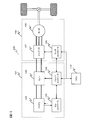
- FIG. 1 is an overall block diagram of a vehicle 100 such as an electric vehicle (EV) equipped with a motor control device according to a first embodiment of the present invention.
- the vehicle includes a power supply unit 101 and a motor drive unit 102.
- the power supply unit 101 includes a battery 103, a cell controller 104 that monitors the battery state, and a relay circuit 105 that enables connection and disconnection of the inverter 107 and the battery 103.
- a battery controller 106 that performs calculation of a state of charge (SOC) of the battery, power supply to the motor driving unit 102, and interruption of power is provided.
- SOC state of charge
- the battery 103 is a battery made of an assembled battery including a plurality of secondary battery cells such as nickel hydride battery cells and lithium battery cells.
- the plurality of secondary battery cells constitute a cell group in which several to a dozen or more are connected in series, and a battery, that is, an assembled battery, includes a plurality of the cell groups connected in series or in series and parallel. ing.
- Battery state data (secondary battery cell terminal voltage, temperature, etc.) acquired by the cell controller 104 is transmitted to the battery controller 106 via a communication path (indicated by an arrow in FIG. 1). Based on the received battery status data, the battery controller 106 calculates the SOC of the entire battery and each secondary battery, the DC power limit value from the battery 103 to the motor drive unit 102, and the like.
- the motor driving unit 102 includes at least one inverter 107 and one motor 108.
- the inverter 107 is driven and controlled by a signal from a motor controller 109 for driving and controlling the motor 108.
- the motor controller 109 generates a drive signal received from the external controller 110 or the like through the communication path or the like, for example, so that the motor is driven with the torque target value or the rotation speed target value, and the motor generated torque or Control the number of revolutions.
- the external controller 110 In the configuration shown in FIG. 1, there is no description of a converter or the like, but these devices may be included.
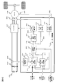
- FIG. 2 illustrates in detail the configuration of the motor control calculation in the motor control device (motor controller) 109 according to the embodiment of the present invention.
- the motor control device 109 includes a DC voltage detection unit 204 that detects the terminal voltage of the capacitor 203 from the output of the DC voltage sensor 202, a motor rotation number detection unit 207 that detects the motor rotation number from the output of the motor rotation sensor 205, and a current sensor 208.
- a motor current detector 209 for detecting a motor drive current from the output of Further, based on the torque command value 210, the motor rotation speed detection value 211, and the DC voltage detection value 212, a first current command calculation unit 213 that calculates an output current in the dq space, a torque command value 210, a motor A second current command calculation unit 216 that calculates an output current in the dq space according to the rotation speed detection value 211, the DC voltage detection value 212, and the battery current target value 215;
- the battery constant current operation request signal 224 causes the normal operation current command value 214, which is an output value from the first current command calculation unit 213, and the battery constant current operation, which is an output value from the second current command calculation unit 216.
- a current command switching unit 218 that switches and outputs the current command value 217.
- a current control value 222 for controlling the three-phase output current to the motor 108 is output.
- a current control calculation unit 221 and a PWM duty calculation unit 223 that determines a PWM duty based on the current control value 222 and generates a signal for driving the inverter 107 with the duty.
- the voltage of the capacitor 203 is theoretically equal to the voltage of the battery 103.
- the first current command calculation unit 213 Based on the torque command value 210 and the current motor rotation speed detection value 211, the first current command calculation unit 213 generates the current command with the least loss within the adjustable range when the motor 108 outputs a desired torque. Determine the value. That is, in normal operation, motor control is performed using the normal control current command value 214 output from the first current command calculation unit 213.
- the second current command calculation unit 216 is configured to output a desired torque from the motor 108 based on the torque command value 210, the current motor rotation speed detection value 211, the DC voltage detection value 212, and the battery current target value 215. The current command for the battery current to become the target value is determined.
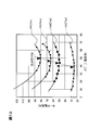
- FIG. 13 shows that the motor 108 is one IPM motor, and that the rotational torque is constant with respect to the motor current that is a three-phase alternating current (amplitude) supplied to the stator coil and its phase (electrical angle). It is a conceptual diagram which shows this curve for every rotational torque.
- the rotation speed of the motor 108 is constant.
- the rotational speed of the motor 108 is constant, that is, the constant speed operation state of the electric vehicle driven by the motor 108.
- the state shown in FIG. 13 is merely one example. Further, when the vehicle is in a downhill state, the motor 108 performs a regenerative operation, so the driving state of the motor 108 as shown in FIG. 13 is not applied.
- a constant rotational torque curve has the smallest motor current value when the phase ⁇ (ie, electrical angle) of the stator coil drive current (motor current) is 40 ° to 50 °.
- the electric angle ⁇ at which the motor current value is minimum is the highest efficiency point of the motor 108.
- the inverter 107 is controlled so that the motor 108 operates at this highest efficiency point, and the motor
- the amplitude and phase of the motor current are controlled by changing the pulse width and phase of the current. For example, in the example of FIG. 13, when the uphill is gradually tightened and a larger rotational torque is required, the motor current and the electrical angle are controlled to change along the maximum efficiency line in the figure.
- the motor controller 109 controls the inverter 107 so that the motor current and the electrical angle become the highest efficiency point in the figure.
- the electrical angle ⁇ can theoretically be close to 90 °. As the torque approaches 90 °, it is necessary to increase the motor current to generate the same torque, so that motor loss and the like increase, resulting in a decrease in efficiency. That is, since the efficiency can be manipulated without changing the motor output, the input power, that is, the battery current can be controlled.
- the control of the constant current operation can be performed on either the right side ( ⁇ increasing direction) or the left side ( ⁇ decreasing direction) of the maximum efficiency curve. Since the change in current is large, it is preferable to perform it on the right side of the maximum efficiency curve. Further, if the above operation is performed across the maximum efficiency curve, two electrical angles ⁇ are possible for the same motor current, and the operation becomes unstable, so that such an operation is not performed. When returning from the constant current operation to the normal operation at the maximum efficiency point, the motor current and its electrical angle are changed along the constant torque curve from the constant current operation point in the reverse procedure.
- the minimum motor current value (which may correspond to ⁇ of the maximum efficiency point) that the motor 108 can output this torque and the heat generation in the motor 108
- the maximum motor current value considered (corresponding to the maximum electrical angle ⁇ ) is stored as a data table, for example, in a storage area of the motor controller 109.
- Two current values corresponding to the motor speed and torque of the normal operation at the highest efficiency point that is, in the above example, the maximum electric angle ⁇ in consideration of the electric angle ⁇ at the highest efficiency point and the heat generation and the output current of the battery.
- the constant current operation is performed using a motor current value between two motor current values respectively corresponding to the angle ⁇ .
- the fluctuation range of ⁇ in the constant speed driving of the vehicle described above can be obtained by actual measurement when driving the vehicle or by simulation or the like, and this fluctuation range of ⁇ is included in the above two motor current values. If so, a constant current operation becomes possible.
- a constant current operation in an actual vehicle, it is necessary to determine whether or not the constant current operation is possible in consideration of the amount of current that can be discharged from the battery 103 based on the state of charge (SOC) of the battery 103. This determination method will be described below.
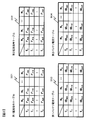
- FIG. 3 shows an example of a data table used in the second current command calculation unit 216.
- the second current command calculation unit 216 includes at least two current command tables 301 and 302 and two battery current tables 303 and 304 corresponding to the battery current as data tables.
- the two current command tables and the two battery current tables may be tables based on, for example, the two motor current values described above (corresponding to the maximum efficiency point ⁇ and the maximum ⁇ ), or the two motors It may be based on values at both ends of any part between the current values.
- the first current command table 301 is a current command table when the battery current is set to the minimum within the adjustable range in the motor rotation speed (range from N0 to Nn) and the torque command (range from T0 to Tn). is there. For example, when the current motor rotation speed is N1 and the torque command is T1, the current command obtained is I * 11x .
- the second current command table 302 is a current command table when the battery current is set to the maximum within the adjustable range in the motor rotation speed (range N0 to Nn) and the torque command (range T0 to Tn). For example, when the current motor rotation speed is N1 and the torque command is T1, the current command to be obtained is I * 11z .
- the first battery current table 303 is an output battery current corresponding to the first current command table 301. For example, as described above, the battery current obtained when the current motor rotation speed is N1 and the torque command is T1. The value is IB 11x .
- the second battery current table 304 is an output battery current corresponding to the second current command table 302. For example, as described above, when the current motor rotation speed is N1 and the torque command is T1, the obtained battery current value is IB 11z .
- Idq * (Idq2 * ⁇ Idq1 * ) / (IB2 ⁇ IB1) ⁇ (IB * ⁇ IB1) + Idq1 * ...
- the values of the first current command table 301 and the value of the first battery current table 303 and the values of the second current command table and the value of the second battery current table 304 have a linear correspondence relationship, respectively.
- the values of the first current command table 301 and the second current command table 302, and the values of the first battery current 303 and the second battery current 304 change strictly linearly. Not done. However, the change in motor current value (first current command table 301 and second current command table) and the change in battery current value (first battery current table 303 and second battery current table 304) are in a linear relationship.
- the target battery current IB * with respect to the target current command value (motor current value) Idq * can be calculated by the above formula (1).
- the first and second battery current tables may be set based on the reference battery voltage VBm, and the battery current target value IB * may be converted into a reference voltage value according to the current battery voltage VB ⁇ .
- the target battery current IB * after conversion is obtained from equation (2).
- IB * IB * ⁇ (VBm / VB ⁇ ) (2)
- the current command table is used in the present embodiment, it is considered that the current command is derived by another means.
- the normal operation mode that is, the operation mode in which the battery current fluctuates due to the fluctuation of the motor load (rotation speed, torque), and the motor load (rotation speed,
- the constant current operation mode in which the battery current is kept constant within a predetermined adjustable range even when the torque) varies can be selected.
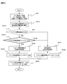
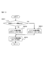
- FIG. 5 is a flowchart for explaining a process for shifting to processing of the motor controller 109 that controls the motor 108 in the battery constant current mode or the normal control mode.
- a torque command T * a motor rotational speed N ⁇ , and a target battery current value IB * are acquired (step S501).
- the first and second current command calculation units 213 and 216 determine current command values in the normal operation mode and the constant current operation mode (step S502).
- step S503 it is determined whether or not the battery constant current operation permission is received from the external controller 110 (step S503). If it is determined that the battery constant current operation is permitted (“permitted” in step S503), it is determined whether or not the battery current target value is within the control range (step S504).
- the battery steady operation permission will be described with reference to FIG.
- step S504 When it is determined that control is possible with the target battery current (“TRUE” in step S504), the battery constant current operation current command value calculated in step S502 is selected (step S505), and the battery constant current operation status is set to “ TRUE ”is set (step S506) and battery constant current operation is started.
- step S503 when the battery constant current operation permission from the external controller 110 is not received (“prohibited” in step S503) or when it is determined that the battery current target value is not within the control range (“FALSE” in step S504).
- the current command value for normal current operation calculated in step S502 is selected (step S507), the battery constant current operation status is set to FALSE (step S508), and normal control operation is started.
- the battery constant current operation status set in steps S506 and S508 is transmitted to the battery controller 106 through the communication path (step S509).
- FIG. 6 is a flowchart illustrating the details of the processing in step S504 in FIG.
- the minimum battery current IB1 is obtained by referring to the first battery current table 303 of FIG. 3 using the torque command T * , the motor rotation speed N ⁇ , and the target battery current value IB * (step S601).
- the maximum battery current IB2 is obtained by referring to the second battery current table 304 of FIG. 3 using the same torque command T * , motor rotation speed N ⁇ , and target battery current value IB * (step S602). .
- target battery current value IB * is not less than minimum battery current IB1 acquired in step S601 and not more than maximum battery current IB2 acquired in step S602 (YES in step S603)
- the battery constant current control range status is set to “TRUE”. (Step S604).
- target battery current value IB * is less than minimum battery current IB1 acquired in step S601 or greater than maximum battery current IB2 acquired in step S602 (NO in step S603)
- the battery constant current control range status is set. “FALSE” is set (step S605).
- the minimum battery current IB1 and the maximum battery current IB2 are the minimum current and the maximum current that can be discharged from the battery 103, respectively. Therefore, the maximum battery current IB2 is set as a value that also considers the state of charge (SOC) of the battery 103.
- SOC state of charge
- the battery controller 106 calculates the SOC after receiving the battery constant current operation status (TRUE) from the motor controller 109.
- FIG. 15 is a flowchart for explaining the SOC calculation process executed by the battery controller 106.
- step S11 it is determined whether or not it is the SOC calculation timing. If it is determined that the SOC calculation timing is reached, the process proceeds to step S12.
- step S12 it is determined whether or not the battery constant current operation status is “True” (details will be described later). If it is determined in step S12 that the battery constant current operation status is “True”, the CCV measurement and the SOC calculation in step S13 are executed. CCV measurement is performed by the cell controller 104 under the control of the battery controller 106. If Steps S11 and S12 are negative, Step S13 is skipped.
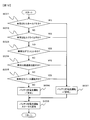
- FIGS. 7 to 12 are flowcharts for explaining first to sixth examples of battery constant current operation permission in which the motor control device of the embodiment according to the present invention can be used. In these cases, the vehicle is almost at a constant speed.
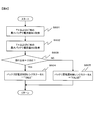
- FIG. 7 is a flowchart for explaining permission of constant current operation in the motor control device when the vehicle is in hill hold.
- the external controller 110 determines whether or not the vehicle traveling is currently in hill hold (step S701). If it is determined that the hill hold is being performed (YES in step S701), the battery constant current operation permission status is set to “permitted” (step S703).
- step S701 when the hill hold is not being performed (NO in step S701), the battery constant current operation permission status is set to “prohibited” (step S702).
- the external controller 110 transmits a battery constant current operation status to the motor controller 109 and the battery controller 106 (step S704).
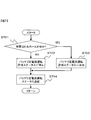
- FIG. 8 is a flowchart for explaining constant current operation permission in the motor control device when the vehicle is in a hill climb.
- the external controller 110 determines whether or not the vehicle is currently driving in a hill climb (step S801). If it is determined that the vehicle is in a hill climb (YES in step S801), the battery constant current operation permission status is set to “permitted” (step S803).
- step S801 when the vehicle is not in a hill climb (NO in step S801), the battery constant current operation permission status is set to “prohibited” (step S802).
- the external controller 110 transmits a battery constant current operation status to the motor controller 109 and the battery controller 106 (step S804).
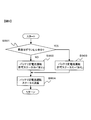
- FIG. 9 is a flowchart for explaining constant current operation permission in the motor control device when the vehicle is downhill.
- the motor 108 does not operate by receiving an alternating current from the inverter 107 but performs a regenerative operation.
- the power generation amount of the motor 108 is constant because the speed is constant, and the direct current flowing through the battery 103 is stabilized as in the case of the constant current operation of the motor 108, the CCV of the secondary battery cell constituting the battery 103 is stable. Measurement can be performed accurately.
- the external controller 110 determines whether or not the vehicle is currently traveling downhill (step S901). If it is determined that the vehicle is downhill (YES in step S901), the battery constant current operation permission status is set to “permitted” (step S903).
- step S902 when the vehicle is not downhill (NO in step S901), the battery constant current operation permission status is set to “prohibited” (step S902).
- the external controller 110 transmits a battery constant current operation status to the motor controller 109 and the battery controller 106 (step S904).
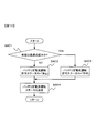
- FIG. 10 is a flowchart for explaining constant current operation permission in the motor control device when the vehicle is traveling at high speed.
- the external controller 110 determines whether or not the vehicle is currently traveling at high speed (step SA01). If it is determined that high-speed cruise is in progress (YES in step SA01), the battery constant current operation permission status is set to “permitted” (step SA03).
- step SA01 when the high-speed cruise is not being performed (NO in step SA01), the battery constant current operation permission status is set to “prohibited” (step SA02).
- the external controller 110 transmits a battery constant current operation status to the motor controller 109 and the battery controller 106 (step SA04).
- FIG. 11 is a flowchart for explaining constant current operation permission in the motor control device when the vehicle is in reverse operation.
- the external controller 110 determines whether or not the vehicle is currently traveling in reverse (step SB01). If it is determined that the reverse operation is being performed (YES in step SB01), the battery constant current operation permission status is set to “permitted” (step SB03).
- step SB01 when the reverse operation is not being performed (NO in step SB01), the battery constant current operation permission status is set to “prohibited” (step SB02).
- the external controller 110 transmits a battery constant current operation status to the motor controller 109 and the battery controller 106 (step SB04).
- FIG. 12 is a flowchart for explaining a seventh example of permitting constant current operation in the motor control apparatus according to the present invention.
- the present embodiment is a collection of the processes of the first to fifth examples. According to this processing, when the condition described in any of the first to fifth examples is satisfied, the battery constant current operation status is set to “permitted” (step SC07).
- step SC06 the battery constant current operation status is set to “prohibited” (step SC06).
- External controller 110 transmits a battery constant current operation status to motor controller 109 and battery controller 106 (step SC08).
- the battery controller 106 compares the SOC calculation result when the battery current fluctuates with the SOC calculation result during battery constant current operation, and corrects the SOC calculation result.
- this invention is not limited to above-described embodiment, Various modified examples are included.
- the above-described embodiment has been described in detail for easy understanding of the present invention, and is not necessarily limited to one having all the configurations described.
- a part of the configuration of an embodiment can be replaced with the configuration of another embodiment, and the configuration of another embodiment can be added to the configuration of an embodiment.
- the configuration, functions, processing, and the like of the above-described embodiments may be realized by hardware by designing a part or all of them, for example, with an integrated circuit. Further, the configuration, functions, and the like of the above-described embodiments may be realized by software by interpreting and executing a program that realizes each function by the processor.
- Information such as programs, tables, and files, which are constituent elements for realizing the above functions, is a recording device such as a memory, a hard disk, or SSD (Solid State Drive), or a recording medium such as an IC card, SD card, or DVD. Can be put in.
- control lines and communication lines are those that are considered necessary for the explanation, and not all control lines and information lines on the product are necessarily shown. In practice, it may be considered that almost all of these components are connected to each other.
Landscapes
- Engineering & Computer Science (AREA)
- Power Engineering (AREA)
- Transportation (AREA)
- Mechanical Engineering (AREA)
- Life Sciences & Earth Sciences (AREA)
- Sustainable Development (AREA)
- Sustainable Energy (AREA)
- Chemical & Material Sciences (AREA)
- Manufacturing & Machinery (AREA)
- Chemical Kinetics & Catalysis (AREA)
- Electrochemistry (AREA)
- General Chemical & Material Sciences (AREA)
- Electric Propulsion And Braking For Vehicles (AREA)
- Control Of Ac Motors In General (AREA)
- Tests Of Electric Status Of Batteries (AREA)
- Secondary Cells (AREA)
Abstract
Description
本発明の第2の態様によると、第1の態様のモータ制御装置において、外部制御装置からの信号に基づいて、モード設定部が第1のモードまたは第2のモードを設定することが好ましい。
本発明の第3の態様によると、第2の態様のモータ制御装置において、モード設定部は、モータのトルク変動が比較的少ないヒルホールド中に第2のモードを設定することが好ましい。
本発明の第4の態様によると、第2の態様のモータ制御装置において、モード設定部は、モータのトルクが放電方向のみとなるヒルクライム中に第2のモードを設定することが好ましい。
本発明の第5の態様によると、第2の態様のモータ制御装置において、モード設定部は、モータのトルクが充電方向のみとなるダウンヒル中に第2のモードを設定することが好ましい。
本発明の第6の態様によると、第2の態様のモータ制御装置において、モード設定部は、モータのトルク変動が比較的少ない高速巡航中に第2のモードを設定することが好ましい。
本発明の第7の態様によると、第2の態様のモータ制御装置において、モード設定部は、モータのトルク変動が比較的少ないリバース運転中に第2のモードを設定することが好ましい。
本発明の第8の態様によると、車両用電動駆動制御装置は、第1の態様のモータ制御装置と、第2のモードでモータが駆動されているときに、二次電池の端子間電圧(CCV)を測定する二次電池電圧測定部と、二次電池電圧測定部で測定された二次電池の端子間電圧(CCV)に基づいて、二次電池のOCVを算出するSOC算出部とを備える。
本発明の第9の態様によると、車両用制御装置は、第1の態様のモータ制御装置と、第2のモードでモータが駆動されているときに、二次電池の端子間電圧(CCV)を測定する二次電池電圧測定部と、二次電池電圧測定部で測定された二次電池の端子間電圧(CCV)に基づいて、二次電池のOCVを算出するSOC算出部と、ヒルホールド、ヒルクライム、高速巡航、およびリバース運転のいずれかを判定する判定部と、判定部がヒルホールド、ヒルクライム、高速巡航、およびリバース運転のいずれかを判定したとき、モータ制御装置に対して第2のモードの設定を指令する指令部とを備える。
図1は、本発明による第1の実施形態のモータ制御装置を搭載した電気自動車(EV)等の車両100の全体ブロック図である。車両は電源部101およびモータ駆動部102を備えている。電源部101には、バッテリ103、バッテリ状態を監視するセルコントローラ104、および、インバータ107とバッテリ103とを接続および切り離しを可能とするリレー回路105を備える。その他、例えばバッテリの充電状態(SOC;State of Charge)の算出やモータ駆動部102への電力供給および遮断などを実施するバッテリコントローラ106を備える。
図13を参照して、本発明によるモータ制御装置における、モータの定電流駆動について説明する。
図13は、モータ108が1つのIPMモータであるとして、この固定子コイルに供給する3相交流電流(振幅)であるモータ電流とその位相(電気角)に対し、回転トルクを一定とする条件の曲線を各回転トルク毎に示す概念図である。
なお、図13では、モータ108の回転数は一定としている。後述するが、モータ108の回転数を一定とする条件、すなわちこのモータ108によって駆動される電動車両の定速運転の状態には種々の状態がある。また運転速度や運転環境によってもモータ回転数や、必要な回転トルクが異なるので、図13に示す状態は単にその1つの例を示すものである。また、車両がダウンヒルの状態では、モータ108は回生動作を行うので図13のようなモータ108の駆動状態は適用されない。
たとえば、図13の例では、登り坂が次第にきつくなり、より大きな回転トルクが必要な場合、図中の最高効率線に沿って、モータ電流と電気角を変化するように制御する。
図14は、説明を簡単にするため図13に示す定トルク曲線の内1つ(τ=50[Nm])のみ抜き出して示したものである。
上記のように通常の動作では、モータ電流と電気角は図中の最高効率点となるように、インバータ107をモータコントローラ109が制御する。
図14の最高効率点から、τ=50[Nm]の定トルク曲線に沿って、所定の定電流動作点(後述)に移動する。このモータ動作点の移動は、モータ電流およびその電気角βを変化させて行う。定トルク状態であるので、車両の定速運転は維持される。定トルク曲線に沿わず、直線的にモータ電流とその電気角を変化させることも可能であるが、運転者にとって意図しない加速/減速が生じるので好ましくない。
また、最高効率曲線を挟んで上記のような動作を行わせると、同じモータ電流に対し2つの電気角βが可能となり、動作が不安定となるので、このような動作は行わない。
なお、定電流動作から最高効率点での通常の動作に戻す場合は、上記と逆の手順で、定電流動作点からモータ電流とその電気角を、定トルク曲線に沿って変化させる。
上記で説明したように、ここでは図13に示す最高効率曲線の右側(β増加方向)で定電流動作を行うとして説明する。
電気角βは、理論的には90°まで可能であるが、90°に近づくにつれて、効率が低下する。この低下した効率の分はモータ108内で熱として発生し、モータの温度が上昇するので、これを考慮してβは適当な範囲で変化させる。さらに、電気角βが90°に近づくと、効率が低下する分だけ大きなモータ電流が必要となるが、これに対応した、バッテリ103からインバータ107への直流電流(バッテリ電流)が可能かどうかも考慮してβを変化させる。
最高効率点での通常の動作の、モータ回転数とトルクに対応した2つの電流値、すなわち上記の例では、最高効率点の電気角βと、発熱およびバッテリの出力電流を考慮した最大の電気角βとにそれぞれ対応した2つのモータ電流値の間のモータ電流値を用いて、上記の定電流動作を行う。
上記で説明した車両の定速運転でのβの変動範囲は車両を駆動した際の実測によって、あるいはシミュレーション等で求めることができ、このβの変動範囲が、上記の2つのモータ電流値に含まれれば、定電流動作が可能となる。
実際の車両での定電流動作では、バッテリ103の充電状態(SOC)に基づくバッテリ103の放電可能な電流量も考慮して、定電流動作が可能かどうかの判断を行う必要がある。
以下にこの判断方法について説明する。
まず、第1電流指令テーブル301よりモータ回転数およびトルク指令に応じて抽出した電流指令値をIdq1*、第1バッテリ電流テーブル303にて抽出した同動作点におけるバッテリ電流値をIB1とする。次に、第2電流指令テーブル302よりモータ回転数およびトルク指令に応じて抽出した電流指令値をIdq2*、第2バッテリ電流テーブル304にて抽出した同動作点におけるバッテリ電流値をIB2とする。
Idq* =(Idq2*-Idq1*)
/(IB2-IB1)×(IB*-IB1)+Idq1*
・・・(1)
なお、第1電流指令テーブル301の値と第1バッテリ電流テーブル303の値、および第2電流指令テーブルの値と第2バッテリ電流テーブル304の値は、それぞれリニアな対応関係にあるが、図13および上記の説明から分かるように、第1電流指令テーブル301の値と第2電流指令テーブル302の値、および第1バッテリ電流303と第2バッテリ電流304の値はそれぞれ厳密にはリニアには変化していない。しかしながら、モータ電流値(第1電流指令テーブル301と第2電流指令テーブル)の変化とバッテリ電流値(第1バッテリ電流テーブル303と第2バッテリ電流テーブル304)の変化はリニアな関係にあるので、上記の式を用いて、目標電流指令値(モータ電流値)Idq*に対する目標バッテリ電流IB*を上記式(1)で算出することができる。
IB* = IB*×(VBm/VB^) ・・・(2)
本実施形態では電流指令テーブルを使用したが、別手段により電流指令を導き出しても同等であると考える。
はじめに、トルク指令T*、モータ回転数N^、目標バッテリ電流値IB*を取得する(ステップS501)。これらのデータを基に、第1および第2電流指令算出部213、216により通常運転モードおよび定電流運転モードにおける電流指令値を決定する(ステップS502)。
なお、このSOC算出タイミングか否かの情報およびバッテリ定電流運転ステータスの情報は、上位制御装置である、外部コントローラ110からバッテリコントローラ106に、たとえば図15の動作を実行する指令とともに送信される。
以下に図7~図12を参照して、バッテリ定電流運転ステータスが“True”かどうかを、外部コントローラ110が判定する種々の車両の運転状態について説明する。
図7は、車両がヒルホールド中の場合のモータ制御装置における定電流運転許可を説明するためのフローチャートである。
外部コントローラ110は、現在車両走行がヒルホールド中であるか否かを判定する(ステップS701)。ヒルホールド中であると判定すると(ステップS701においてYES)、バッテリ定電流運転許可ステータスを「許可」に設定する(ステップS703)。
図8は、車両がヒルクライム中の場合のモータ制御装置における定電流運転許可を説明するためのフローチャートである。
外部コントローラ110は、現在車両走行がヒルクライム中であるか否かを判定する(ステップS801)。ヒルクライム中であると判定すると(ステップS801においてYES)、バッテリ定電流運転許可ステータスを「許可」に設定する(ステップS803)。
図9は、車両がダウンヒル中の場合のモータ制御装置における定電流運転許可を説明するためのフローチャートである。定速で車両がダウンヒル中の場合は、モータ108は、インバータ107からの交流電流を受けて動作しているのではなく、回生動作を行っている。しかし、定速であるのでモータ108の発電量が一定であり、モータ108の定電流動作の場合と同様にバッテリ103を流れる直流電流が安定するので、バッテリ103を構成する二次電池セルのCCV測定を正確に行うことができる。
図10は、車両が高速巡航中の場合のモータ制御装置における定電流運転許可を説明するためのフローチャートである。
外部コントローラ110は、現在車両走行が高速巡航中であるか否かを判定する(ステップSA01)。高速巡航中であると判定すると(ステップSA01においてYES)、バッテリ定電流運転許可ステータスを「許可」に設定する(ステップSA03)。
図11は、車両がリバース運転中の場合のモータ制御装置における定電流運転許可を説明するためのフローチャートである。
外部コントローラ110は、現在車両走行がリバース運転中であるか否かを判定する(ステップSB01)。リバース運転中であると判定すると(ステップSB01においてYES)、バッテリ定電流運転許可ステータスを「許可」に設定する(ステップSB03)。
図12は、本発明によるモータ制御装置における定電流運転許可の第7の例を説明するためのフローチャートである。
本実施形態は上記の第1乃至第5の例の処理を集約したものである。この処理によれば、第1乃至第5の例のいずれかに記載された条件が成立した場合に、バッテリ定電流運転ステータスを「許可」にする(ステップSC07)。
日本国特許出願2011年第209814号(2011年9月26日出願)
Claims (9)
- モータの負荷変動により二次電池の充放電電流が変化する第1のモードと、前記モータの負荷変動に拘わらず、前記二次電池の充放電電流が所定時間は一定になる第2のモードとのいずれかのモードを設定するモード設定部と、
前記モード設定部により設定されたモードと、トルク指令値と、モータ回転数とに基づいて、前記モータを駆動する駆動信号を生成する駆動信号生成部とを備えるモータ制御装置。 - 請求項1に記載のモータ制御装置において、
外部制御装置からの信号に基づいて、前記モード設定部が前記第1のモードまたは前記第2のモードを設定するモータ制御装置。 - 請求項2に記載のモータ制御装置において、
前記モード設定部は、前記モータのトルク変動が比較的少ないヒルホールド中に前記第2のモードを設定するモータ制御装置。 - 請求項2に記載のモータ制御装置において、
前記モード設定部は、前記モータのトルクが放電方向のみとなるヒルクライム中に前記第2のモードを設定するモータ制御装置。 - 請求項2に記載のモータ制御装置において、
前記モード設定部は、前記モータのトルクが充電方向のみとなるダウンヒル中に前記第2のモードを設定するモータ制御装置。 - 請求項2に記載のモータ制御装置において、
前記モード設定部は、前記モータのトルク変動が比較的少ない高速巡航中に前記第2のモードを設定するモータ制御装置。 - 請求項2に記載のモータ制御装置において、
前記モード設定部は、前記モータのトルク変動が比較的少ないリバース運転中に前記第2のモードを設定するモータ制御装置。 - 請求項1に記載のモータ制御装置と、
前記第2のモードで前記モータが駆動されているときに、前記二次電池の端子間電圧(CCV)を測定する二次電池電圧測定部と、
前記二次電池電圧測定部で測定された前記二次電池の端子間電圧(CCV)に基づいて、前記二次電池のOCVを算出するSOC算出部とを備える車両用電動駆動制御装置。 - 請求項1に記載のモータ制御装置と、
前記第2のモードで前記モータが駆動されているときに、前記二次電池の端子間電圧(CCV)を測定する二次電池電圧測定部と、
前記二次電池電圧測定部で測定された前記二次電池の端子間電圧(CCV)に基づいて、前記二次電池のOCVを算出するSOC算出部と、
ヒルホールド、ヒルクライム、高速巡航、およびリバース運転のいずれかを判定する判定部と、
前記判定部が前記ヒルホールド、ヒルクライム、高速巡航、およびリバース運転のいずれかを判定したとき、前記モータ制御装置に対して前記第2のモードの設定を指令する指令部とを備える車両用制御装置。
Priority Applications (3)
| Application Number | Priority Date | Filing Date | Title |
|---|---|---|---|
| DE112012004011.2T DE112012004011T5 (de) | 2011-09-26 | 2012-07-25 | Motorsteuervorrichtung |
| US14/343,088 US9490741B2 (en) | 2011-09-26 | 2012-07-25 | Motor control device |
| CN201280040021.5A CN103765758B (zh) | 2011-09-26 | 2012-07-25 | 电动机控制装置 |
Applications Claiming Priority (2)
| Application Number | Priority Date | Filing Date | Title |
|---|---|---|---|
| JP2011-209814 | 2011-09-26 | ||
| JP2011209814A JP5670851B2 (ja) | 2011-09-26 | 2011-09-26 | モータ制御装置および車両用制御装置 |
Publications (1)
| Publication Number | Publication Date |
|---|---|
| WO2013046893A1 true WO2013046893A1 (ja) | 2013-04-04 |
Family
ID=47994948
Family Applications (1)
| Application Number | Title | Priority Date | Filing Date |
|---|---|---|---|
| PCT/JP2012/068851 Ceased WO2013046893A1 (ja) | 2011-09-26 | 2012-07-25 | モータ制御装置 |
Country Status (5)
| Country | Link |
|---|---|
| US (1) | US9490741B2 (ja) |
| JP (1) | JP5670851B2 (ja) |
| CN (1) | CN103765758B (ja) |
| DE (1) | DE112012004011T5 (ja) |
| WO (1) | WO2013046893A1 (ja) |
Families Citing this family (12)
| Publication number | Priority date | Publication date | Assignee | Title |
|---|---|---|---|---|
| US9381826B2 (en) | 2012-10-19 | 2016-07-05 | Gogoro Inc. | Battery configuration for an electric vehicle |
| WO2017037496A1 (en) * | 2015-08-29 | 2017-03-09 | Abb Technology Ltd. | System having electrical machine and controller |
| JP6569490B2 (ja) * | 2015-11-17 | 2019-09-04 | オムロン株式会社 | バッテリパックおよびこれを備えたバッテリシステム、バッテリパックの用途判別方法 |
| JP2017093253A (ja) | 2015-11-17 | 2017-05-25 | オムロン株式会社 | バッテリパックおよびこれを備えたバッテリシステム |
| JP6597219B2 (ja) | 2015-11-17 | 2019-10-30 | オムロン株式会社 | バッテリパックおよびこれを備えたバッテリシステム |
| KR102548679B1 (ko) * | 2015-12-14 | 2023-06-27 | 현대모비스 주식회사 | 차량용 모터 제어 장치 및 이를 이용한 전류 지령 생성 방법 |
| JP6875866B2 (ja) * | 2017-01-20 | 2021-05-26 | 矢崎総業株式会社 | 電池状態検出装置 |
| DE102018106308B4 (de) * | 2018-03-19 | 2020-02-13 | Dr. Ing. H.C. F. Porsche Aktiengesellschaft | Modulationsindexverbesserung durch intelligente Batterie |
| KR102645052B1 (ko) * | 2019-03-05 | 2024-03-08 | 현대자동차주식회사 | 하이브리드 차량의 주행모드 제어 장치 및 그 방법 |
| CN110588655A (zh) * | 2019-09-04 | 2019-12-20 | 湖南猎豹汽车股份有限公司 | 一种纯电动汽车多模式控制方法 |
| DE102019126268A1 (de) * | 2019-09-30 | 2021-04-01 | Audi Ag | Bestimmung der Rotortemperatur einer PSM |
| KR102727992B1 (ko) * | 2020-04-21 | 2024-11-07 | 현대자동차주식회사 | 전기자동차의 안전 충전 시스템 및 방법 |
Citations (5)
| Publication number | Priority date | Publication date | Assignee | Title |
|---|---|---|---|---|
| JPH0662503A (ja) * | 1992-08-05 | 1994-03-04 | Pfu Ltd | バッテリ搭載走行体運転支援処理方式 |
| JP2004007978A (ja) * | 2002-05-21 | 2004-01-08 | Ford Motor Co | ハイブリッド電気自動車のためのバッテリーの充電及び/又は放電の制御方法 |
| JP2008276970A (ja) * | 2007-04-25 | 2008-11-13 | Toyota Motor Corp | 電源システム、電源システムの制御方法、および電源システムの制御方法をコンピュータに実行させるためのプログラムを記録したコンピュータ読取可能な記録媒体 |
| JP2009208512A (ja) * | 2008-02-29 | 2009-09-17 | Mitsubishi Heavy Ind Ltd | 作業用車両の制御方法および作業用車両 |
| JP2011097729A (ja) * | 2009-10-29 | 2011-05-12 | Toyota Motor Corp | 車両の電源装置 |
Family Cites Families (7)
| Publication number | Priority date | Publication date | Assignee | Title |
|---|---|---|---|---|
| US5825155A (en) * | 1993-08-09 | 1998-10-20 | Kabushiki Kaisha Toshiba | Battery set structure and charge/ discharge control apparatus for lithium-ion battery |
| JP4466600B2 (ja) * | 2006-03-31 | 2010-05-26 | アイシン・エィ・ダブリュ株式会社 | 電動駆動制御装置及び電動駆動制御方法 |
| JP4264843B2 (ja) * | 2007-03-30 | 2009-05-20 | トヨタ自動車株式会社 | ハイブリッド車両の制御装置 |
| US7743860B2 (en) * | 2007-10-09 | 2010-06-29 | Ford Global Technologies, Llc | Holding a hybrid electric vehicle on an inclined surface |
| JP5028294B2 (ja) * | 2008-02-14 | 2012-09-19 | 日立オートモティブシステムズ株式会社 | レゾルバの異常検出装置 |
| JP5549121B2 (ja) * | 2008-06-17 | 2014-07-16 | 三洋電機株式会社 | 組電池の電圧検出装置及びこれを具えたバッテリシステム |
| JP4692646B2 (ja) * | 2009-02-04 | 2011-06-01 | 株式会社デンソー | 動力発生源制御装置 |
-
2011
- 2011-09-26 JP JP2011209814A patent/JP5670851B2/ja active Active
-
2012
- 2012-07-25 CN CN201280040021.5A patent/CN103765758B/zh not_active Expired - Fee Related
- 2012-07-25 US US14/343,088 patent/US9490741B2/en active Active
- 2012-07-25 WO PCT/JP2012/068851 patent/WO2013046893A1/ja not_active Ceased
- 2012-07-25 DE DE112012004011.2T patent/DE112012004011T5/de active Pending
Patent Citations (5)
| Publication number | Priority date | Publication date | Assignee | Title |
|---|---|---|---|---|
| JPH0662503A (ja) * | 1992-08-05 | 1994-03-04 | Pfu Ltd | バッテリ搭載走行体運転支援処理方式 |
| JP2004007978A (ja) * | 2002-05-21 | 2004-01-08 | Ford Motor Co | ハイブリッド電気自動車のためのバッテリーの充電及び/又は放電の制御方法 |
| JP2008276970A (ja) * | 2007-04-25 | 2008-11-13 | Toyota Motor Corp | 電源システム、電源システムの制御方法、および電源システムの制御方法をコンピュータに実行させるためのプログラムを記録したコンピュータ読取可能な記録媒体 |
| JP2009208512A (ja) * | 2008-02-29 | 2009-09-17 | Mitsubishi Heavy Ind Ltd | 作業用車両の制御方法および作業用車両 |
| JP2011097729A (ja) * | 2009-10-29 | 2011-05-12 | Toyota Motor Corp | 車両の電源装置 |
Also Published As
| Publication number | Publication date |
|---|---|
| CN103765758A (zh) | 2014-04-30 |
| JP5670851B2 (ja) | 2015-02-18 |
| US20140217935A1 (en) | 2014-08-07 |
| JP2013074640A (ja) | 2013-04-22 |
| US9490741B2 (en) | 2016-11-08 |
| DE112012004011T5 (de) | 2014-07-10 |
| CN103765758B (zh) | 2016-08-17 |
Similar Documents
| Publication | Publication Date | Title |
|---|---|---|
| JP5670851B2 (ja) | モータ制御装置および車両用制御装置 | |
| CN110289649B (zh) | 通过智能电池改善调制指数 | |
| US7656690B2 (en) | Voltage conversion device and computer-readable recording medium with program recorded thereon for computer to execute control of voltage conversion by voltage conversion device | |
| US8098050B2 (en) | Charge/discharge control device for secondary battery and vehicle equipped with the same | |
| JP5182504B2 (ja) | 電力供給装置およびその制御方法 | |
| JP5932596B2 (ja) | 車両の回生制御装置 | |
| US9190896B2 (en) | PWM strategy for reduction of inverter hotspot temperature and overall losses | |
| KR101488866B1 (ko) | 전동 차량용 축전 시스템 | |
| US10040368B2 (en) | Power supply system, transportation device, and power transmission method including changing a proportion of a charging prower | |
| US20170151886A1 (en) | Power supply system, transportation device, and power transmission method | |
| US10574143B2 (en) | Power supply device, machine, and control method for performing power conversion using a multiphase converter | |
| JP6412847B2 (ja) | 蓄電装置及び制御方法 | |
| US20170244338A1 (en) | Power supply device, apparatus, and control method | |
| US10170988B2 (en) | Power supply system | |
| CN108604862A (zh) | 电源装置、设备及控制方法 | |
| US20180323707A1 (en) | Vehicular motor control device and vehicular motor control method | |
| US20170244337A1 (en) | Power supply system, apparatus, and control method | |
| US10300906B2 (en) | Power supply system, transportation device, and power transmission method | |
| US20240012063A1 (en) | State of health based operation for vehicle power sources` | |
| CN108702090B (zh) | 电源装置、设备及控制方法 | |
| JP2021099951A (ja) | 電池システム | |
| JP2008295123A (ja) | 車載用電源装置 | |
| US11909344B2 (en) | Control device | |
| JP2017050920A (ja) | 回転電機制御装置 | |
| JP5351202B2 (ja) | 車両の発電制御装置 |
Legal Events
| Date | Code | Title | Description |
|---|---|---|---|
| 121 | Ep: the epo has been informed by wipo that ep was designated in this application |
Ref document number: 12835482 Country of ref document: EP Kind code of ref document: A1 |
|
| WWE | Wipo information: entry into national phase |
Ref document number: 14343088 Country of ref document: US |
|
| WWE | Wipo information: entry into national phase |
Ref document number: 112012004011 Country of ref document: DE Ref document number: 1120120040112 Country of ref document: DE |
|
| 122 | Ep: pct application non-entry in european phase |
Ref document number: 12835482 Country of ref document: EP Kind code of ref document: A1 |