WO2013042498A1 - 手術システム - Google Patents
手術システム Download PDFInfo
- Publication number
- WO2013042498A1 WO2013042498A1 PCT/JP2012/070891 JP2012070891W WO2013042498A1 WO 2013042498 A1 WO2013042498 A1 WO 2013042498A1 JP 2012070891 W JP2012070891 W JP 2012070891W WO 2013042498 A1 WO2013042498 A1 WO 2013042498A1
- Authority
- WO
- WIPO (PCT)
- Prior art keywords
- signal
- unit
- control unit
- frequency signal
- frequency
- Prior art date
Links
Images


Classifications
-
- A—HUMAN NECESSITIES
- A61—MEDICAL OR VETERINARY SCIENCE; HYGIENE
- A61B—DIAGNOSIS; SURGERY; IDENTIFICATION
- A61B18/00—Surgical instruments, devices or methods for transferring non-mechanical forms of energy to or from the body
- A61B18/04—Surgical instruments, devices or methods for transferring non-mechanical forms of energy to or from the body by heating
- A61B18/12—Surgical instruments, devices or methods for transferring non-mechanical forms of energy to or from the body by heating by passing a current through the tissue to be heated, e.g. high-frequency current
- A61B18/14—Probes or electrodes therefor
- A61B18/1402—Probes for open surgery
-
- A—HUMAN NECESSITIES
- A61—MEDICAL OR VETERINARY SCIENCE; HYGIENE
- A61B—DIAGNOSIS; SURGERY; IDENTIFICATION
- A61B18/00—Surgical instruments, devices or methods for transferring non-mechanical forms of energy to or from the body
- A61B18/04—Surgical instruments, devices or methods for transferring non-mechanical forms of energy to or from the body by heating
- A61B18/12—Surgical instruments, devices or methods for transferring non-mechanical forms of energy to or from the body by heating by passing a current through the tissue to be heated, e.g. high-frequency current
- A61B18/1206—Generators therefor
-
- A—HUMAN NECESSITIES
- A61—MEDICAL OR VETERINARY SCIENCE; HYGIENE
- A61B—DIAGNOSIS; SURGERY; IDENTIFICATION
- A61B17/00—Surgical instruments, devices or methods, e.g. tourniquets
- A61B17/32—Surgical cutting instruments
- A61B17/320068—Surgical cutting instruments using mechanical vibrations, e.g. ultrasonic
- A61B2017/320069—Surgical cutting instruments using mechanical vibrations, e.g. ultrasonic for ablating tissue
-
- A—HUMAN NECESSITIES
- A61—MEDICAL OR VETERINARY SCIENCE; HYGIENE
- A61B—DIAGNOSIS; SURGERY; IDENTIFICATION
- A61B17/00—Surgical instruments, devices or methods, e.g. tourniquets
- A61B17/32—Surgical cutting instruments
- A61B17/320068—Surgical cutting instruments using mechanical vibrations, e.g. ultrasonic
- A61B2017/320082—Surgical cutting instruments using mechanical vibrations, e.g. ultrasonic for incising tissue
-
- A—HUMAN NECESSITIES
- A61—MEDICAL OR VETERINARY SCIENCE; HYGIENE
- A61B—DIAGNOSIS; SURGERY; IDENTIFICATION
- A61B18/00—Surgical instruments, devices or methods for transferring non-mechanical forms of energy to or from the body
- A61B2018/00636—Sensing and controlling the application of energy
- A61B2018/00773—Sensed parameters
- A61B2018/00845—Frequency
-
- A—HUMAN NECESSITIES
- A61—MEDICAL OR VETERINARY SCIENCE; HYGIENE
- A61B—DIAGNOSIS; SURGERY; IDENTIFICATION
- A61B18/00—Surgical instruments, devices or methods for transferring non-mechanical forms of energy to or from the body
- A61B2018/00636—Sensing and controlling the application of energy
- A61B2018/00773—Sensed parameters
- A61B2018/00869—Phase
-
- A—HUMAN NECESSITIES
- A61—MEDICAL OR VETERINARY SCIENCE; HYGIENE
- A61B—DIAGNOSIS; SURGERY; IDENTIFICATION
- A61B18/00—Surgical instruments, devices or methods for transferring non-mechanical forms of energy to or from the body
- A61B2018/0091—Handpieces of the surgical instrument or device
- A61B2018/00916—Handpieces of the surgical instrument or device with means for switching or controlling the main function of the instrument or device
- A61B2018/00928—Handpieces of the surgical instrument or device with means for switching or controlling the main function of the instrument or device by sending a signal to an external energy source
-
- A—HUMAN NECESSITIES
- A61—MEDICAL OR VETERINARY SCIENCE; HYGIENE
- A61B—DIAGNOSIS; SURGERY; IDENTIFICATION
- A61B90/00—Instruments, implements or accessories specially adapted for surgery or diagnosis and not covered by any of the groups A61B1/00 - A61B50/00, e.g. for luxation treatment or for protecting wound edges
- A61B90/06—Measuring instruments not otherwise provided for
- A61B2090/064—Measuring instruments not otherwise provided for for measuring force, pressure or mechanical tension
- A61B2090/065—Measuring instruments not otherwise provided for for measuring force, pressure or mechanical tension for measuring contact or contact pressure
Definitions
- the present invention relates to a surgical system including a handpiece to which ultrasonic energy and high frequency energy are applied simultaneously.
- monopolar handpieces that use high-frequency currents are used when incising or coagulating living tissue.
- the incision mode for performing incision and the coagulation mode for performing coagulation are switched by a waveform of a high-frequency current applied to the treatment portion 9 of the handpiece.
- a continuous-wave high-frequency current high-frequency energy
- the living tissue is evaporated by large heat generation.
- the coagulation mode by applying a high-frequency current of an intermittent wave (burst wave), the living tissue is held at a temperature at which proteins and the like coagulate.
- burst wave intermittent wave
- hemostasis can be performed while incising a living tissue.
- Japanese Patent Application Laid-Open No. 2002-306507 discloses that not only high-frequency current but also ultrasonic vibration is applied to the treatment unit 9 to prevent the living tissue from being burnt to the treatment unit 9.
- Japanese Patent Application Laid-Open No. 2010-5370 discloses a surgical system that detects an ultrasonic impedance corresponding to the ultrasonic vibration of the treatment section 9 to which a high-frequency current and ultrasonic vibration are applied, and controls the high-frequency current. ing.
- the effect of the conventional surgical system comprising a handpiece to which high-frequency current and ultrasonic vibration are applied is the effect obtained by applying only high-frequency current, the effect obtained by applying only ultrasonic vibration, Was simply added.
- an object is to provide a surgical system with good operability.
- the surgical operation system includes a drive signal output unit that outputs a drive signal, a high-frequency signal output unit that outputs a high-frequency signal, an ultrasonic wave that is applied with the high-frequency signal and an ultrasonic transducer is generated by the drive signal.
- a probe having a treatment section that performs hemostasis processing while drawing an incision line in the pressing direction when pressed against a real tissue by a synergistic effect of the drive signal and the high-frequency signal, and a return circuit for the high-frequency signal A counter electrode plate to be formed; a high-frequency signal main control unit that performs feedback control of the high-frequency signal output unit based on the high-frequency signal; and a drive signal main control unit that performs feedback control of the drive signal output unit based on the drive signal; Based on the drive signal, the high-frequency signal main unit controls the high-frequency signal output unit to stop the output of the high-frequency signal. Comprising a short high-frequency signal auxiliary controller response time than control section.
- a surgical system is a treatment unit that simultaneously performs high-frequency treatment and ultrasonic treatment on a tissue, the treatment unit performing hemostasis while drawing an incision line in the tissue, and the treatment unit
- a drive signal output unit for outputting a drive signal for ultrasonic treatment, a drive signal detection unit for detecting a parameter of the drive signal output by the drive signal output unit, and the parameter detected by the drive signal detection unit
- a drive signal main control unit that feedback-controls the drive signal output unit based on the high frequency signal output unit that outputs a high frequency signal for the high frequency treatment to the treatment unit, and the high frequency signal output unit outputs A high-frequency signal detection unit for detecting a parameter of the high-frequency signal; and the high-frequency signal output unit based on the parameter detected by the high-frequency signal detection unit.
- a high-frequency signal auxiliary control unit that controls the high-frequency signal output unit to stop the output of the high-frequency signal and has a response time shorter than that of the high-frequency signal main control unit; and the high-frequency signal output to the treatment unit And a recovery unit that forms a return circuit.
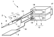
- a surgical system 1 includes a handpiece 2, an ultrasonic transducer drive signal generator (hereinafter referred to as “US device”) 5, and a high-frequency current signal generator (hereinafter referred to as “HV device”). 6) and a counter electrode plate 3 as a collection part.
- US device ultrasonic transducer drive signal generator
- HV device high-frequency current signal generator
- the US device 5 and the HV device 6 may be a signal generator 10 that is housed in a single housing and shares some functions.
- the monopolar handpiece 2 is a surgical instrument having a treatment section 9 at the tip.
- the US device 5 generates a drive signal (hereinafter referred to as “US signal”) for driving the ultrasonic transducer 23 (see FIG. 2) built in the handpiece 2.
- the HV device 6 supplies a high frequency signal (hereinafter referred to as “HV signal”) to the handpiece 2.
- the counter electrode plate 3 serving as a recovery unit is arranged so as to come into contact with a patient's buttocks or the like over a wide area, and forms a return circuit for an HV signal.
- the handpiece 2 includes a gripping portion 7 that the operator grips, a shaft portion 8 that protrudes forward from the gripping portion 7, and a treatment portion 9 that is disposed at the tip of the shaft portion 8.
- a selection switch 11 (11 a, 11 b, 11 c) for selecting a treatment to be performed by the treatment unit 9 is disposed on the grip unit 7.
- a US cable 13, a hand switch cable 14, and an HV cable 15 are extended from the rear end side of the grip portion 7 of the handpiece 2.
- the connectors of the US cable 13 and the hand switch cable 14 are detachably connected to the US device 5.
- the HV cable 15 has a connector at an end thereof detachably connected to the HV device 6.
- a connector at the end of a counter electrode cable 16 connected to the counter electrode plate 3 is also detachably connected to the HV device 6.
- the US device 5 and the HV device 6 transmit and receive signals via a connected communication cable 17.
- the US apparatus 5 and the HV apparatus 6 have front panels 18 and 19 for performing display and operation input, respectively.
- the US device 5 and the HV device 6 may be operable by a foot switch or the like.
- the handpiece 2 includes a substantially cylindrical main case 21 that constitutes the gripping portion 7 and a sub case 22 that is connected to the end portion of the handpiece 2 to form a storage portion.
- An ultrasonic transducer (US transducer) 23 connected to the US cable 13 is disposed inside the main case 21.
- the ultrasonic transducer 23 is composed of a plurality of ring-shaped electrostrictive elements 24 fastened by bolts 25 and nuts 26.
- a US signal is applied to the electrodes provided on each surface of the electrostrictive element 24, the ultrasonic transducer 23 vibrates ultrasonically.
- the ultrasonic vibration is transmitted to the treatment portion 9 via the shaft portion 8 constituted by the horn 27 and the probe 28 connected to the front end of the ultrasonic transducer 23 (bolt 25).
- the probe 28 is inserted into a metal pipe 30 covered with an insulating pipe 29.
- the nut 26 is made of metal and is also a conductor portion to which the conductive wire of the HV cable 15 is connected.
- the HV signal applied to the nut 26 is transmitted to the metal treatment section 9 via the metal bolt 25 and the metal probe 28.
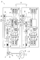
- a US device 5 that generates a US signal and supplies ultrasonic (US) energy to the treatment unit 9 includes a central processing unit (CPU) 51, a US signal detection unit 52, an A / D conversion unit 53, and an output transformer 54.
- the output transformer 54, the amplifier 55, the waveform generation unit 56, the PLL unit 57, and the power source 58 constitute a drive signal output unit (US signal output unit) 50.
- the US signal is, for example, a sinusoidal AC signal having a predetermined fundamental frequency (resonance frequency).
- the CPU 51 that controls the entire US device 5 includes a drive signal calculation unit (US signal calculation unit) 51a, a drive signal main control unit (US signal main control unit) 51c, and a high-frequency signal auxiliary control unit (HV signal auxiliary control unit). ) 51b.
- the US signal calculation unit 51a, the US signal main control unit 51c, and the HV signal auxiliary control unit 51b may be configured by different CPUs.
- the waveform generator 56 generates, for example, a sine wave signal.
- the sine wave signal generated by the waveform generator 56 is amplified by the amplifier 55 and then applied to the primary winding side of the output transformer 54, and as a US signal from the output terminal on the secondary winding side of the output transformer 54, Applied to the ultrasonic transducer 23 of the handpiece 2.
- the US signal intensity that is, the ultrasonic output of the ultrasonic transducer 23 is adjusted according to the output voltage of the power source 58.
- the output voltage of the power source 58 that is, the ultrasonic output and the operation of the waveform generator 56 are controlled by the US signal main controller 51c.
- the US signal main control unit 51c generates an ultrasonic output corresponding to the setting operation based on the US signal (parameter) detected by the US signal detection unit 52 according to the setting operation by the setting unit 18a of the front panel 18 or the like.
- the output voltage and the like of the power source 58 are controlled so that
- the front panel 18 is provided with a display unit 18b that displays information such as the US signal intensity output from the CPU 51. That is, the US signal main control unit 51c performs feedback control.
- the sine wave signal amplified by the amplifier 55 is input to the current (I) detection unit 52 a and the voltage (V) detection unit 52 b that constitute the US signal detection unit 52. Further, the sine wave signal is input to the PLL unit 57.
- the PLL unit 57 performs PLL control so that the ultrasonic transducer 23 is driven by a US signal having the resonance frequency.
- the PLL unit 57 controls the phase of the voltage of the US signal and the phase of the current to be in phase.
- the operation of the PLL unit 57 is controlled by the US signal main control unit 51c.
- the US current signal detection unit 52a and the US signal voltage detection unit 52b convert the sine wave signal amplified by the amplifier 55 into an effective value (RMS).
- the effective value of the voltage and the effective value of the current are converted into digital signals by the A / D converter 53 (53a, 53b) and input to the CPU 51, respectively.
- the US signal calculation unit 51a calculates the US signal intensity (US signal output) using the digital signal having the input voltage effective value or current effective value.
- the HV device 6 that generates an HV signal and supplies high frequency (HV) energy to the treatment unit 9 includes a central processing unit (CPU) 61, an HV signal detection unit 62, an A / D conversion unit 63, and an output transformer. 64, an amplifier 65, a waveform generation unit 66, a resonance unit 67, a power source 68, and a high-frequency signal relay (HV signal relay) 69.
- the amplifier 65, the waveform generation unit 66, the resonance unit 67, the power source 68, and the HV signal relay 69 constitute a high frequency signal output unit (HV signal output unit) 60.
- the HV signal is, for example, a sine wave AC signal having a predetermined fundamental frequency.
- the HV signal relay 69 is a switch that turns ON / OFF the output of the signal input from the power supply 68 to the subsequent circuit. That is, the HV signal relay 69 outputs a signal to the subsequent circuit in the ON state (conductive state), but does not output a signal to the subsequent circuit in the OFF state (open state).
- the CPU 61 that controls the entire HV device 6 includes a high-frequency signal calculation unit (HV signal calculation unit) 61a and a high-frequency signal main control unit (HV signal main control unit) 61c.
- the HV signal calculation unit 61a and the HV signal main control unit 61c may be configured by different CPUs. Further, the CPU 61 may be the same CPU as the CPU 51.
- the waveform generation unit 66 generates at least a coagulation waveform signal.
- 4A is a continuous waveform incision waveform signal composed of continuous sine wave signals shown in FIG. 4A
- the coagulation waveform signal shown in FIG. 4B is an intermittent wave
- a decaying sine wave signal period (maximum amplitude) gradually decreases ( Ton) and a burst wave having one cycle are repeated from the signal stop period (Toff).
- the signal output from the waveform generation unit 66 is input to the amplifier 65 via the resonance unit 67.
- the signal amplified by the amplifier 65 is applied to the primary winding side of the output transformer 64, and an HV signal is generated on the secondary winding side.
- One end of the secondary winding of the output transformer 64 is electrically connected to the horn 27 and the like of the handpiece 2.
- the other end of the secondary winding is electrically connected to the counter electrode plate 3 that contacts the patient 40 over a wide area.
- the resonance unit 67 is supplied with power from a voltage-variable power source 68.
- the waveform generator 66 and the power source 68 are controlled by the HV signal main controller 61c.
- the HV signal main control unit 61c controls the output voltage of the power source 68 based on the HV signal (parameter) detected by the HV signal detection unit 62 in accordance with the setting operation by the setting unit 19a of the front panel 19 or the like. , HV signal output is adjusted. That is, the HV signal main control unit 61c performs feedback control.
- the CPU 61 may variably control the crest factor CF by changing the amplitude, attenuation pattern, and / or signal stop period (Toff) of the sine wave constituting the coagulation waveform. it can.
- the front panel 19 is provided with a display unit 19b for displaying HV signal information.
- the signal amplified by the amplifier 65 is input to a current (I) detection unit 62 a and a voltage (V) detection unit 62 b that constitute the HV signal detection unit 62.
- the HV signal detection unit 62 converts the signal amplified by the amplifier 65 into an effective value.
- the effective value of the voltage and the effective value of the current are converted into digital signals by the A / D converter 63 (63a, 63b), respectively, and input to the CPU 61.
- the HV signal calculation unit 61a calculates the HV signal output using the digital signal having the input voltage effective value or current effective value.
- Feedback control that is normal control performed by the US signal main control unit 61c and the HV signal main control unit 51c is, for example, control for maintaining the signal intensity at a predetermined intensity.
- the HV signal auxiliary control unit 51b controls the HV signal relay 69 of the HV signal output unit 60 to the ON state or the OFF state based on the US signal detected by the US signal detection unit 52. That is, the control performed by the HV signal auxiliary control unit 51b is ON / OFF control that only stops signal output, and therefore high-speed control with a short response time is relatively easy compared to normal control that increases or decreases the output. realizable.
- high energy discharge a spark discharge having a large energy
- the treatment section 9 when the treatment section 9 is separated from the tissue containing fat being treated, a high energy discharge may occur, which may accelerate the deterioration of the treatment section 9.
- the HV signal auxiliary control unit 51 b detects that the treatment unit 9 is separated from the tissue based on the US signal detected by the US signal detection unit 52, the HV signal output from the HV signal output unit 60.
- the relay 69 is controlled to be in an OFF state. That is, the application of the HV signal to the treatment unit 9 is stopped very shortly after the detection of the US signal. For this reason, even if the treatment part 9 leaves
- the HV signal auxiliary control unit 51b prevents the generation of the high energy discharge by stopping the output before the high energy discharge occurs based on the signal change caused by the precursor phenomenon or the like.
- the HV signal auxiliary control unit 51b has a shorter response time than the HV signal main control unit 51c. That is, the response time of the US signal main control unit 51c and the HV signal main control unit 61c that performs feedback control is preferably 5 ms (milliseconds) or longer, for example, 100 ms.
- the response time of the HV signal auxiliary control unit 51b is preferably 1 ms or less, for example, 0.5 ms. Further, since the HV signal relay 69 is a simple operation circuit of ON / OFF operation, the response time is 1 ms or less, for example, 0.2 ms.
- the HV signal relay 69 may be a mechanical switch or a semiconductor switch.
- an attenuation unit that makes the signal output substantially zero, i.e., reduces the signal strength to a level that does not affect the treatment or the like. It may be used.
- the function of the attenuation unit may be realized by controlling the amplifier 65. That is, in the following description and the like, “stopping signal output” is a concept including the case of “making signal output substantially zero”. For example, when the voltage of the HV signal is 200 Vp or less, no medical effect is exerted on the living tissue, and no high energy discharge is generated. However, since it is an inexpensive switch with a fast response speed, it is most preferable to use a relay.
- the US signal detector 52 detects signals at intervals of 1 ms or less.
- the HV signal auxiliary control unit 51b sequentially processes the signals detected by the US signal detection unit 52 at intervals of 1 ms or less, but the US signal main control unit 51c has a predetermined interval longer than the detection interval of the US signal detection unit 52.
- the signal detected by the US signal detector 52 is processed at an interval of 100 ms.
- the US signal main control unit 51c may perform control using an integrated value or an average value of signals detected by the US signal detection unit 52 at intervals of 1 ms or less.
- the HV signal main control unit 61c processes the signal detected by the HV signal detection unit 62 at an interval of 100 ms, for example.
- the US signal detection unit 52 may include a US signal main detection unit 52A and a US signal auxiliary detection unit 52B. Further, the US signal detected by the US signal main detection unit 52A and the US signal detected by the US signal auxiliary detection unit 52B may be sampled from the same location on the circuit or may be sampled from different locations. .
- the US signal auxiliary detection unit 52B has a detection interval shorter than that of the US signal main detection unit 52A.
- the US signal main detection unit 52A detects signals at intervals of 5 ms or more, for example, 100 ms
- the US signal auxiliary detection unit 52B detects signals at intervals of 1 ms or less, for example, 0.5 ms. To do.
- the HV signal main control unit 61c performs normal feedback control based on the signal detected by the HV signal main detection unit 62A, and the HV signal auxiliary control unit 51b receives the signal detected by the US signal auxiliary detection unit 52B. Based on high-speed control with fast response speed.
- the US signal main control unit 51c performs normal feedback control based on the signal detected by the US signal main detection unit 52A.
- the US signal main control unit 51c and the HV signal main control unit 61c can be stably controlled as long as the detection / response loop processing time is not less than the above range. That is, in the feedback control, if the detection interval and the response time are too short, for example, the signal output may be excessively increased in response to a noise signal that appears in pulses. For this reason, the signal detection interval and the response time of the US signal main control unit 51c and the HV signal main control unit 61c are preferably within the above ranges.
- the HV signal auxiliary control unit 51b needs to stop the output of the HV signal before the high energy discharge occurs when the treatment unit 9 comes into contact with another tool made of metal.
- the time from the detection of the US signal to the completion of the operation of the HV signal relay 69 by the control of the HV signal auxiliary control unit 51b is 1 ms or less.
- the occurrence of high energy discharge can be surely prevented within the following time.
- the detection interval, the response time, and the time until completion of the operation are all preferably short, but in an industrially available system, the lower limit is about 1 ⁇ s (microseconds).
- the US signal feedback-controlled by the US signal main control unit 51c is applied to the ultrasonic transducer 23, and the treatment unit 9 is ultrasonically vibrated.
- an HV signal (high-frequency current) feedback-controlled by the HV signal main control unit 61c flows from the treatment unit 9 to the organ 41.
- the HV signal that has flowed to the organ 41 returns to the HV device 6 through the body of the patient 40, the counter electrode 3, and the counter electrode cable 16.
- HV energy is applied to the treatment target as Joule heat due to contact resistance between the treatment section 9 and the organ 41 or heat and shock waves due to a discharge phenomenon between the treatment section 9 and the organ 41.
- the above-described components do not have to be independent components (circuits or the like), and may be functional units that are executed by programs read by the CPUs 51 and 61.
- the surgeon presses the treatment unit 9 against the organ 41 that is a real tissue while simultaneously applying the HV signal and the US signal to the treatment unit 9 of the handpiece 2.
- the hemostasis can be performed while drawing the incision line 42 in the pressing direction.
- the “real tissue (parenchyma ⁇ organ)” is a tissue in a living body, for example, an organ such as a liver.
- the medical term “cut” includes three treatments: “excision”, “exfoliation”, and “make an incision line”.
- cutting such as polyps or “peeling” such as the diaphragm is cutting that cuts off the tissue
- the energy can be concentrated at the cutting site by sandwiching and holding the tissue to be cut.
- a handpiece having a probe tip to which only ultrasonic energy is applied and a jaw that sandwiches and holds the tissue jointly the mechanical friction force by US energy and the heat generated by friction are applied to the held tissue.
- An incision is possible.
- incision can be made on the grasped tissue without applying US energy.
- a “handpiece that draws an incision line” cannot be performed on a handpiece that sandwiches and holds tissue.
- the treatment portion 9 that is ultrasonically vibrated is pressed against the tissue, the pressing force is not as strong as the gripping force by the bipole handpiece. . For this reason, frictional force and heat generation due to friction are small, and the tissue cannot be cut mechanically or thermally. Further, the treatment section 9 to which only the coagulation waveform HV signal (HV energy) is applied does not generate enough heat to evaporate the living tissue, and an incision line cannot be drawn.
- HV signal HV energy
- the effect obtained by applying only the high-frequency current and the effect obtained by applying only the ultrasonic vibration are not simply combined effects, but the sum of the effects brought by each of them.
- the above effect that is, a synergistic effect is obtained.
- the HV signal is a coagulation waveform.
- living tissue cannot be evaporated only by the HV signal of the coagulation waveform.
- FIG. 6 in the surgical system 1, by applying a coagulation waveform HV signal together with the US signal to the treatment unit 9, hemostasis can be performed while drawing an incision line in the liver in the pressing direction of the treatment unit 9. .
- the treatment is performed in a state where no ultrasonic vibration is applied, that is, in a state where only the HV signal is applied, even if the operator presses the treatment unit 9 in the intended direction of the organ 41.
- the HV signal of the coagulation waveform from the part 9 flows isotropically with respect to the surrounding tissue. For example, many discharges due to the HV signal occur not only in the pressing direction of the treatment section 9 but also in a direction orthogonal to the pressing direction. For this reason, as shown in FIG. 7A, large heat generation does not occur locally, and a tissue 43 is formed around the treatment portion 9 by coagulation due to thermal denaturation and evaporation of moisture to increase the impedance.
- the HV signal of the coagulation waveform from the treatment portion 9 changes in the pressing direction. Concentrates on the organization. In other words, the discharge due to the coagulation waveform HV signal concentrates in the space between the treatment section 9 and the tissue in the pressing direction. That is, directionality occurs in the discharge by the HV signal. For this reason, even if the HV signal has a coagulation waveform, the pressed tissue is evaporated by a large heat generation, and the incision line 42 is drawn in the pressing direction.
- the wall surface (incision surface) of the tissue in the direction orthogonal to the traveling direction of the treatment portion 9 becomes longer from the treatment portion 9. Therefore, HV signals are not concentrated compared to the traveling direction. For this reason, the cut surface has a temperature suitable for coagulation, moisture is evaporated, and the impedance is increased. For this reason, the tissue in the pressing direction of the treatment portion 9, that is, the tissue in the traveling direction evaporates, while the tissue on the incised surface that has passed the treatment portion 9 is hemostatic.
- the HV signal concentrates on the low impedance region of the real tissue generated by the ultrasonic vibration of the treatment unit 9. That is, when the treatment portion 9 that is ultrasonically vibrated and to which the HV signal is applied is pressed in a predetermined direction, only the pressed region of the high impedance real tissue around the treatment portion 9 is super Physically peeled off by sonic vibration. Thereby, the real structure
- the treatment section 9 repeats a contact state or a non-contact state according to the tissue in the pressing direction and ultrasonic vibration. That is, when the treatment unit 9 that is ultrasonically vibrated is pressed, the distance between the treatment unit 9 and the tissue in the pressing direction varies. In addition, at the moment when the treatment unit 9 is not in contact with the tissue, the air pressure in the space between the treatment unit 9 and the tissue is low. Conversely, at the moment when the treatment unit 9 comes into contact with the tissue, the atmospheric pressure in the space between the treatment unit 9 and the tissue increases. That is, the pressure in the space between the treatment unit 9 and the tissue in the pressing direction varies according to the ultrasonic vibration of the treatment unit 9.
- the HV signal applied to the treatment unit 9 is locally concentrated on the tissue in the pressing direction. Therefore, anisotropy occurs in the discharge direction.
- the HV signal concentrates along a path where fine particles composed of components (water, oily components and water-oil mixed components) scattered from the real tissue by ultrasonic vibration exist. That is, when the treatment section 9 that is ultrasonically vibrated is pressed, the tissue is crushed by the ultrasonic vibration, further atomized, and becomes fine particles and floats in the space. The water constituting the tissue is water vapor fine particles, and the oil component is oil fine particles. Mixed fine particles containing water and oil components are also generated. For this reason, in the space between the treatment part 9 and the tissue, fine particles composed of components dispersed from the tissue are unevenly distributed. For this reason, HV signals concentrate along the path along which fine particles composed of components dispersed from the tissue exist. Therefore, directionality occurs in the discharge by the HV signal.
- components water, oily components and water-oil mixed components
- the HV signal applied simultaneously with the US signal is effective as long as it is a coagulation waveform, but is preferably 30 W or more and 70 W or less. If it is equal to or lower than the lower limit, an incision line can be drawn in the pressing direction by the HV signal concentrated on the extreme part, and if it is equal to or lower than the upper limit, the tissue passed by the treatment portion 9 can be coagulated and hemostatic.
- the crest factor CF of the coagulation waveform of the HV signal is preferably 5 or more, more preferably 5.5 or more, and particularly preferably 6 or more.
- an incision line can be drawn in the pressing direction by the HV signal concentrated on the extreme part, and the tissue that has passed the treatment part 9 can be coagulated and hemostatic.
- the upper limit value of the crest factor CF is not particularly limited, but is preferably 10 or less, for example, from the specifications of the HV device.
- the ultrasonic vibration of the treatment portion 9 by the US signal has a vibration speed of 8 m / second or more and 18 m / second or less. Moreover, it is preferable that the ultrasonic vibration of the treatment portion 9 by the US signal has an amplitude larger than 0 ⁇ m and smaller than 200 ⁇ m.
- the frequency of the US signal is 47 kHz
- the amplitude of the treatment section 9 is 60 ⁇ m at a vibration speed of 8 m / second
- the amplitude of the treatment section 9 is 120 ⁇ m at a vibration speed of 18 m / second.
- the US signal main control unit 51c When the treatment is started, the US signal main control unit 51c outputs a US signal corresponding to the set value of the setting unit 18a based on the value detected by the US signal voltage detection unit 52b of the US signal detection unit 52.
- the US signal output unit 50 is feedback-controlled.
- the HV signal main control unit 61c is configured so that the HV signal output has a coagulation waveform corresponding to the set value of the setting unit 19a based on the value detected by the HV signal current detection unit 62a of the HV signal detection unit 62.
- the signal output unit 60 is feedback-controlled.
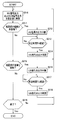
- Step S11 When the HV signal auxiliary control unit 51b detects that the treatment unit 9 is separated from the tissue based on, for example, the change value (differential value) of the impedance of the US signal detected by the US signal detection unit 62 (S11; Yes) ), The processing from step S12 is performed.
- the HV signal auxiliary control unit 51b controls the HV signal relay 69 to the OFF state (open state).
- the time from the detection of the US signal to the stop of application of the HV signal to the treatment unit 9 is 1 ms or less.
- the treatment unit 9 is separated from the tissue based on the US signal, particularly in the processing of a fat-rich tissue in which high energy discharge is likely to occur, even in a non-contact state.
- the change in the HV signal is small compared to the time, but the change in the US signal is large. That is, since a tissue with a lot of fat has a high electric resistance, the HV signal does not change greatly even when it is in a non-contact state as compared with a contact state.
- the US signal is brought into a non-contact state, the mechanical load is greatly reduced, so that a large change is generated as compared with the contact state.
- the US signal for detecting that the treatment unit 9 is separated from the tissue is not limited to the change value of the impedance of the US signal, and may be a US signal detected by various configurations as described later. .
- the HV signal auxiliary control unit 51b maintains the HV signal relay 69 in the OFF state until a predetermined HV signal output standby time TH of 15 ms elapses (S13; No).
- the HV signal auxiliary control unit 51b controls the HV signal relay 69 to the ON state (conducting state) after a predetermined HV signal output standby time TH has elapsed (S13; Yes). That is, the HV signal auxiliary control unit 51b controls the HV signal output unit 60 so as to restart the output of the stopped HV signal.
- the surgical system 1 has good operability because the output of the HV signal is automatically restarted after the predetermined HV signal output standby time TH has elapsed.
- the HV signal output standby time TH is preferably 5 ms to 50 ms, particularly preferably 10 ms to 20 ms. If it is in the said range, a high energy discharge will not generate
- Step S19> Until the treatment is completed (S19: Yes), the processing from step S10 is repeated.
- the surgical system 1 includes the dedicated HV signal auxiliary control unit 51b for performing high-speed control for stopping the output of the HV signal when the treatment unit 9 leaves the tissue.
- the surgical system 1 can efficiently perform treatment due to the synergistic effect of ultrasonic vibration and high-frequency current, and has a shorter response time than the HV signal main control unit 61C that controls the HV signal output unit 60 based on the US signal. Since the signal auxiliary control unit 51b is provided, the generation of high energy discharge is suppressed even if the treatment unit 9 is separated from the tissue.
- the surgical system 1 can perform hemostasis while drawing an incision line in the pressing direction by simultaneously applying ultrasonic vibration and high-frequency current to the treatment portion, and can generate a spark discharge with high energy (high energy There is no risk of discharge) and operability is good.
- the HV signal auxiliary control unit 51b performs control based on the integration value of the signal in the frequency band of the frequency from the basic frequency to twice the basic frequency included in the US signal.
- the current waveform of the US signal is distorted. That is, as shown in FIG. 9, at the time of contact, the US signal, which is a sine wave of the fundamental frequency (f0) that is the resonance frequency, contains more high frequency components than at the time of non-contact.
- the treatment unit 9 is separated from the tissue. I can judge.
- the intensity of the signal in the frequency band (f0 to 2f0) from the fundamental frequency (f0) to twice the fundamental frequency (2f0) is extracted from the US signal using a bandpass filter, for example.
- the HV signal auxiliary control unit 51b performs control based on the change rate of the signal intensity in the frequency band (f0 to 2f0), that is, the differential value, because higher speed control is possible.
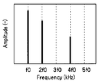
- the HV signal auxiliary control unit 51b performs control based on a signal of an odd multiple of the fundamental frequency included in the US signal.
- the amplitude of the US signal in the contact state shown in FIG. 10B is particularly a frequency that is an odd multiple of the fundamental frequency (f0). (3f0, 5f0,...)
- the amplitude of a signal having a frequency (3f0) three times the fundamental frequency (f0) and a US signal having a frequency (5f0) five times the fundamental frequency (f0) is extracted from the US signal by a bandpass filter. From the viewpoint of the intensity of the extractable signal and the circuit mounting cost, it is preferable to extract the signal of (3f0 and 5f0), but only the signal of (3f0) may be extracted, or (3f0, 5f0, 7f0... ) Signal or the like may be extracted.
- the HV signal auxiliary control unit 51b performs control based on the change rate of the extracted signal, that is, the differential value, because higher speed control is possible.
- the HV signal auxiliary control unit 51b performs control based on the phase difference between the voltage and current of the US signal.
- the US signal of the US device 5 is PLL-controlled by the PLL unit 57 of the secondary circuit via the output transformer 54 as shown in FIG. FIG. 11 shows only some of the components of the surgical system.
- the output transformer 54 that insulates between the patient circuit and the secondary circuit is designed so that it can be driven at a maximum current and a maximum voltage for a long time. For this reason, in the patient circuit without the PLL unit 57, when the treatment unit 9 is not in contact with the tissue, that is, when the mechanical load (load) is small, the voltage of the US signal is much lower than the maximum voltage. It becomes. Then, as shown in FIG. 12, when the load is small, the phase difference between the voltage and current of the US signal increases.
- the US signal detection unit 52 having the US signal auxiliary detection unit 52B for detecting the US signal of the patient circuit allows the patient to Based on the phase difference between the current and voltage of the US signal of the circuit, it is possible to detect that the treatment section 9 is not in contact with the tissue.
- the HV signal auxiliary control unit 51b performs control based on the detected signal change speed, that is, the differential value, because higher speed control is possible.
- the HV signal auxiliary control unit 51b performs control based on the change rate of the resonance frequency of the US vibrator.
- the PLL unit 27 changes the fundamental frequency in accordance with the change in the resonance frequency of the US vibrator.
- the resonance frequency changes according to the contact / non-contact of the treatment portion 9 with the tissue, that is, according to the mechanical load of the treatment portion 9.
- the resonance frequency also changes depending on the temperature.
- the US signal auxiliary detection unit 52B detects the change rate (differential value) of the resonance frequency, and the HV signal auxiliary control unit 51b determines that the treatment unit 9 is caused by the occurrence of a sudden change in which the change rate is equal to or higher than a predetermined value. Detects contact with the tissue.
- the structure which can be used with the surgery system 1 is not restricted to the structure demonstrated above, The various structure which has the same effect can be used. Two or more configurations may be used in combination. For example, using configuration 1 and configuration 2, when the level of at least one of the US signals becomes equal to or higher than a predetermined value, the HV signal auxiliary control unit 51b may stop outputting the HV signal.
- a surgical system 1A according to a modification of the first embodiment will be described.
- the surgical system 1 ⁇ / b> A of the present modification is similar to the surgical system 1 of the first embodiment, and thus the same reference numerals are given to components having the same functions, and descriptions thereof are omitted.
- the HV signal auxiliary control unit 51b of the surgical system 1A also performs control to stop the output of the US signal simultaneously with the control to stop the output of the HV signal when the treatment unit 9 leaves the tissue.
- a US signal relay 59 which is a switch for turning on / off the output of the signal input from 58 to the subsequent circuit is provided. That is, the US signal relay 59 outputs a signal to the subsequent circuit in the ON state (conductive state), but does not output a signal to the subsequent circuit in the OFF state (open state).
- the HV signal auxiliary control unit 51 b controls not only the HV signal relay 69 but also the US signal relay 59.
- the surgical system 1A has the effects of the surgical system 1 and can more reliably prevent the occurrence of high energy discharge. In other words, the operative system 1A has better operability than the operative system 1.
- the HV signal auxiliary control unit 51b controls the HV signal output unit 60 to resume the output of the stopped HV signal after a predetermined HV signal output standby time, and similarly outputs the stopped US signal. It is preferable to control the US signal output unit 50 so as to resume after the US signal output standby time.
- the surgical system 101 includes the US signal auxiliary control unit 61b that controls the US signal output unit 50 based on the HV signal and has a response time shorter than that of the US signal main control unit 51c.
- a US device 5 that generates a US signal and supplies ultrasonic (US) energy to the treatment unit 9 includes a central processing unit (CPU) 51, a US signal detection unit 52, an A / D conversion unit 53, and an output transformer 54.
- the output transformer 54, the amplifier 55, the waveform generation unit 56, the PLL unit 57, the power supply 58, and the US signal relay 59 constitute a drive signal output unit (US signal output unit) 50.
- the US signal is, for example, a sinusoidal AC signal having a predetermined fundamental frequency (resonance frequency).
- the US signal relay 59 is an ON / OFF switch that cuts off the output of the signal input from the power supply 58 to the subsequent circuit. That is, the US signal relay 59 outputs a signal to the subsequent circuit in the ON state (conductive state), but does not output a signal to the subsequent circuit in the OFF state (open state).
- the CPU 61 that controls the entire HV device 6 and controls the US signal relay 59 includes a high-frequency signal calculation unit (HV signal calculation unit) 61a, a drive signal auxiliary control unit (US signal auxiliary control unit) 61b, and a high-frequency signal main control. Part (HV signal main control part) 61c.
- the HV signal calculation unit 61a, the US signal auxiliary control unit 61b, and the HV signal main control unit 61c may be configured by different CPUs. Further, the CPU 61 may be the same CPU as the CPU 51.
- Feedback control that is normal control performed by the US signal main control unit 61c and the HV signal main control unit 51c is, for example, control for maintaining the signal intensity at a predetermined intensity.
- the US signal auxiliary control unit 61b controls the US signal relay 59 of the US signal output unit 50 to the ON state or the OFF state based on the HV signal detected by the HV signal detection unit 62. That is, the control performed by the US signal auxiliary control unit 61b is ON / OFF control that only stops the output of the signal, so that high-speed control with a short response time is relatively easy compared to the normal control that increases or decreases the output. realizable.
- high energy discharge As described above, in the treatment using the handpiece in which the ultrasonic vibration and the high-frequency current are simultaneously applied to the treatment portion, the energy that is difficult to be generated in the treatment using the handpiece in which only the high-frequency current is applied to the treatment portion is large. There was a risk of spark discharge (hereinafter referred to as “high energy discharge”).
- the US signal output unit 50 US signal relays 59 are controlled to be in an OFF state. That is, the ultrasonic vibration of the treatment unit 9 stops after a very short time after the detection of the HV signal. For this reason, even if the treatment part 9 contacts with another treatment tool, high energy discharge does not occur.
- the US signal auxiliary control unit 61b prevents the generation of the high energy discharge by stopping the output before the high energy discharge occurs based on the signal change caused by the precursor phenomenon or the like.
- the US signal auxiliary control unit 61b has a shorter response time than the US signal main control unit 61c. That is, the response time of the US signal main control unit 51c and the HV signal main control unit 61c that performs feedback control is preferably 5 ms (milliseconds) or longer, for example, 100 ms.
- the response time of the US signal auxiliary control unit 61b is preferably 1 ms or less, for example, 0.5 ms. Further, since the US signal relay 59 is also a simple operation circuit of ON / OFF operation, the response time is 1 ms or less, for example, 0.2 ms.
- the US signal relay 59 may be a mechanical switch or a semiconductor switch.
- an attenuation unit that makes the signal output substantially zero, i.e., reduces the signal strength to a level that does not affect the treatment or the like. It may be used.
- the function of the attenuation unit may be realized by controlling the amplifier 55. That is, in the following description and the like, “stopping signal output” is a concept including the case of “making signal output substantially zero”.
- the HV signal detection unit 62 detects signals at intervals of 1 ms or less.
- the US signal main control unit 51c processes the signal detected by the US signal detection unit 52 at an interval of 100 ms.
- the US signal auxiliary control unit 61b sequentially processes the signals detected by the HV signal detection unit 62 at intervals of 1 ms or less, but the HV signal main control unit 61c is a predetermined interval longer than the detection interval of the HV signal detection unit 62.
- the signal detected by the HV signal detection unit 62 is processed at an interval of 100 ms.
- the HV signal main control unit 61c may perform control using an integrated value or an average value of signals detected by the HV signal detection unit 62 at intervals of 1 ms or less.
- the HV signal detection unit 62 may include an HV signal main detection unit 62A and an HV signal auxiliary detection unit 62B.
- the HV signal detected by the HV signal main detection unit 62A and the HV signal detected by the HV signal auxiliary detection unit 62B may be sampled from the same location on the circuit or from different locations. .
- HV signal auxiliary detection unit 62B has a detection interval shorter than HV signal main detection unit 62A.
- the HV signal main detection unit 62A detects signals at intervals of 5 ms or more, for example, 100 ms
- the HV signal auxiliary detection unit 62B detects signals at intervals of 1 ms or less, for example, 0.5 ms. To do.
- the HV signal main control unit 61c performs normal feedback control based on the signal detected by the HV signal main detection unit 62A.
- the US signal main control unit 51c performs normal feedback control based on the signal detected by the US signal main detection unit 52A, and the US signal auxiliary control unit 61b receives the signal detected by the HV signal auxiliary detection unit 62B. Based on high-speed control with fast response speed.
- the US signal main control unit 51c and the HV signal main control unit 61c can be stably controlled as long as the detection / response loop processing time is not less than the above range. That is, in the feedback control, if the detection interval and the response time are too short, for example, the signal output may be excessively increased in response to a noise signal that appears in pulses. For this reason, the signal detection interval and the response time of the US signal main control unit 51c and the HV signal main control unit 61c are preferably within the above ranges.
- the US signal auxiliary control unit 61b needs to stop the output of the HV signal before the high energy discharge occurs when the treatment unit 9 leaves the tissue.
- the time from the detection of the HV signal to the completion of the operation of the US signal relay 59 by the control of the US signal auxiliary control unit 61b is 1 ms or less.
- the occurrence of high energy discharge can be surely prevented within the following time.
- the detection interval, the response time, and the time until completion of the operation are all preferably short, but in an industrially available system, the lower limit is about 1 ⁇ s (microseconds).
- Step S110> This is the same as step S10 in FIG.
- Step S115 When the US signal auxiliary control unit 61b detects that the treatment unit 9 is in contact with the metal tool based on, for example, the differential value of the current of the HV signal (S15; Yes), the processing from step S116 is performed.
- Step S116> The US signal auxiliary control unit 61b stops the HV signal within 1 ms after the HV signal detection.
- the US signal auxiliary control unit 61b controls the US signal relay 59 to the OFF state (open state).
- the time from the detection of the HV signal to the stop of the application of the US signal to the ultrasonic transducer 23 is 1 ms or less.
- the signal for detecting that the treatment unit 9 has come into contact with the metal tool is not limited to the differential value of the current of the HV signal detected by the HV signal detection unit 62, and is detected by various configurations as will be described later. It may be an HV signal.
- the US signal auxiliary control unit 61b maintains the OFF state of the US signal relay 59 until a predetermined US signal output standby time TU of 150 ms elapses (S117; No).
- the US signal auxiliary control unit 61b controls the US signal relay 59 to the ON state (conduction state) after a predetermined US signal output standby time TU has elapsed (S117; Yes). That is, the US signal auxiliary control unit 61b controls the US signal output unit 50 to resume the output of the stopped US signal.
- the operation system 101 has good operability because the output of the US signal is automatically restarted after a predetermined US signal output standby time TH has elapsed.
- the US signal output standby time TU is preferably 50 ms to 500 ms, particularly preferably 100 ms to 200 ms. If it is in the said range, a high energy discharge will not generate
- Step S119> Until the treatment is completed (S119: Yes), the processing from step S110 is repeated.
- the surgical system 101 includes the dedicated US signal auxiliary control unit 61b for performing high-speed control for stopping the output of the US signal when the treatment unit 9 comes into contact with the metal tool. .
- the surgical system 101 can perform treatment efficiently due to the synergistic effect of ultrasonic vibration and high-frequency current, and even if the treatment unit 9 comes into contact with a metal tool, the occurrence of high energy discharge is suppressed. ing.
- the operation system 101 has good operability.
- the US signal auxiliary control unit 61b performs control based on a signal having a frequency higher than the fundamental frequency included in the HV signal.
- the resistance decreases, and a large current flows as an HV signal. Even before complete contact, a weak discharge is generated from the treatment section 9 to the metal tool. Then, a signal having a frequency higher than the fundamental frequency starts to be generated in the current of the HV signal composed of a sine wave having a predetermined fundamental frequency, for example, 350 kHz.
- the HV signal includes a signal having a frequency higher than the fundamental frequency.
- the US signal auxiliary control unit 61b performs control based on the detected signal intensity change rate, that is, the differential value, because higher speed control is possible.
- the US signal auxiliary control unit 61b performs control based on the change rate of the effective value of the HV signal.
- the current value (effective value) of the HV signal starts to increase rapidly.
- the current value of the HV signal increases above a predetermined value, high energy discharge occurs.
- the US signal auxiliary control unit 61b can stop the US signal before high energy discharge occurs by performing control based on the rate of change of the current value (effective value) of the HV signal, that is, the differential value.
- the US signal auxiliary control unit 61b performs control based on the distortion component of the HV signal.
- the magnitude of the distortion increases as the specific resistance of the object with which the treatment unit 9 comes into contact increases. For example, distortion occurs even when the treatment unit 9 comes into contact with adipose tissue, but the magnitude of the distortion is smaller than when it comes into contact with red tissue. Also, the magnitude of strain when in contact with metal tools is much greater than when in contact with lean tissue. For this reason, this configuration is unlikely to malfunction.
- the structure which can be used with the surgery system 101 is not restricted to the structure demonstrated above, The various structure which has the same effect can be used. Two or more configurations may be used in combination.
- the US signal auxiliary control unit 61b of the surgery system 101A also performs control for stopping the output of the HV signal simultaneously with the control for stopping the output of the US signal when the treatment unit 9 comes into contact with another tool made of metal.
- the HV signal output unit 60 is provided with an HV signal relay 69 which is an ON / OFF switch for cutting off the output of the signal input from the power source 68 to the subsequent circuit. That is, the HV signal relay 69 outputs a signal to the subsequent circuit in the ON state (conductive state), but does not output a signal to the subsequent circuit in the OFF state (open state).
- HV signal relay 69 which is an ON / OFF switch for cutting off the output of the signal input from the power source 68 to the subsequent circuit. That is, the HV signal relay 69 outputs a signal to the subsequent circuit in the ON state (conductive state), but does not output a signal to the subsequent circuit in the OFF state (open state).
- the US signal auxiliary control unit 61b controls not only the US signal relay 59 but also the HV signal relay 69.
- the operation system 101A has the effect of the operation system 101, and more reliably generates high energy discharge. Can be prevented. That is, the operative system 101A has better operability than the operative system 101.
- the US signal auxiliary control unit 61b controls the US signal output unit 50 to resume the output of the stopped US signal after a predetermined US signal output standby time, and similarly outputs the output of the stopped HV signal. It is preferable to control the HV signal output unit 60 so as to resume after the HV signal output standby time.
- the surgery system 201 has both the configuration of the surgery system 1 and the configuration of the surgery system 101. That is, the surgical operation system 201 controls the US signal output unit 50 based on the HV signal, the US signal auxiliary control unit 61b having a response time shorter than that of the US signal main control unit 51c, and the HV signal output unit 60 based on the US signal. And an HV signal auxiliary control unit 51b having a response time shorter than that of the HV signal main control unit 61C.
- the US signal main control unit 51c When the treatment is started, the US signal main control unit 51c outputs a US signal corresponding to the set value of the setting unit 18a based on the value detected by the US signal voltage detection unit 52b of the US signal detection unit 52.
- the US signal output unit 50 is feedback-controlled.
- the HV signal main control unit 61c is configured so that the HV signal output has a coagulation waveform corresponding to the set value of the setting unit 19a based on the value detected by the HV signal current detection unit 62a of the HV signal detection unit 62.
- the signal output unit 60 is feedback-controlled.
- the output of the HV signal is performed by processing from step S11 described later. Stop immediately.
- Step S211 When the HV signal auxiliary control unit 51b detects that the treatment unit 9 is separated from the tissue based on, for example, the change value (differential value) of the impedance of the US signal detected by the US signal detection unit 62 (S211; Yes) ), The process from step S212 is performed.
- the HV signal auxiliary control unit 51b controls the HV signal relay 69 to the OFF state (open state).
- the time from the detection of the US signal to the stop of the application of the HV signal to the treatment unit 9 is 1 ms or less.
- the treatment unit 9 is separated from the tissue based on the US signal, particularly in the processing of a fat-rich tissue in which high energy discharge is likely to occur, even in a non-contact state.
- the change in the HV signal is small compared to the time, but the change in the US signal is large. That is, since a tissue with a lot of fat has a high electric resistance, the HV signal does not change greatly even when it is in a non-contact state as compared with a contact state.
- the US signal is brought into a non-contact state, the mechanical load is greatly reduced, so that a large change is generated as compared with the contact state.
- the US signal for detecting that the treatment unit 9 is separated from the tissue is not limited to the change value of the impedance of the US signal, and may be a US signal detected by various configurations as described later. .
- Step S213 For example, the HV signal auxiliary control unit 51b maintains the OFF state of the HV signal relay 69 until a predetermined HV signal output standby time TH of 15 ms elapses (S213; No).
- the HV signal auxiliary control unit 51b controls the HV signal relay 69 to the ON state (conducting state) after a predetermined HV signal output standby time TH has elapsed (S213; Yes). That is, the HV signal auxiliary control unit 51b controls the HV signal output unit 60 so as to restart the output of the stopped HV signal.
- the surgical system 201 has good operability because the output of the HV signal is automatically restarted after a predetermined HV signal output standby time TH has elapsed.
- the HV signal output standby time TH is preferably 5 ms to 50 ms, particularly preferably 10 ms to 20 ms. If it is in the said range, a high energy discharge will not generate
- Step S215 When the US signal auxiliary control unit 61b detects that the treatment unit 9 is in contact with the metal tool based on, for example, the differential value of the current of the HV signal (S15; Yes), the processing from step S216 is performed.
- Step S216> The US signal auxiliary control unit 61b stops the HV signal within 1 ms after the HV signal detection.
- the US signal auxiliary control unit 61b controls the US signal relay 59 to the OFF state (open state).
- the time from the detection of the HV signal to the stop of the application of the US signal to the ultrasonic transducer 23 is 1 ms or less.
- the signal for detecting that the treatment unit 9 has come into contact with the metal tool is not limited to the differential value of the current of the HV signal detected by the HV signal detection unit 62, and is detected by various configurations as will be described later. It may be an HV signal.
- Step S217 For example, the US signal auxiliary control unit 61b maintains the OFF state of the US signal relay 59 until a predetermined US signal output standby time TU of 150 ms elapses (S217; No).
- the US signal auxiliary control unit 61b controls the US signal relay 59 to the ON state (conductive state) after a predetermined US signal output standby time TU has elapsed (S217; Yes). That is, the US signal auxiliary control unit 61b controls the US signal output unit 50 to resume the output of the stopped US signal.
- the surgical system 201 has good operability because the output of the US signal is automatically restarted after a predetermined US signal output standby time TH has elapsed.
- the US signal output standby time TU is preferably 50 ms to 500 ms, particularly preferably 100 ms to 200 ms. If it is in the said range, a high energy discharge will not generate
- the US signal output standby time TU is set longer than the HV signal output standby time TH.
- the mechanical energy (US signal) has a slower effective response speed than the electrical energy (HV signal). This is because high energy discharge may not be prevented by stopping for a short time. That is, even when the application of the US signal to the ultrasonic transducer 23 is stopped, the vibration of the treatment unit 9 is not stopped immediately.
- Step S219> Until the treatment is completed (S219: Yes), the processing from step S210 is repeated.
- the treatment unit 9 includes a dedicated HV signal auxiliary control unit 51b for performing high-speed control for stopping the output of the HV signal when the treatment unit 9 leaves the tissue, and the treatment unit 9.
- the surgical system 201 can efficiently perform treatment due to the synergistic effect of ultrasonic vibration and high-frequency current, and the treatment unit 9 may be separated from the tissue or the treatment unit 9 may be in contact with a metal tool. However, the occurrence of high energy discharge is suppressed.
- the operation system 201 has good operability.
- the same structure as the surgery system 1 or the surgery system 201 can be used.
- a surgical operation system 201A according to a modified example of the third embodiment will be described.
- the surgical operation system 201A of the present modification is similar to the surgical operation system 201 of the third embodiment, and thus components having the same functions are denoted by the same reference numerals and description thereof is omitted.
- the HV signal auxiliary control unit 51b of the surgical system 201A also performs control for stopping the output of the US signal simultaneously with the control for stopping the output of the HV signal when the treatment unit 9 leaves the tissue. Further, the US signal auxiliary control unit 61b of the surgical system 201A also performs control for stopping the output of the HV signal simultaneously with the control for stopping the output of the US signal when the treatment unit 9 comes into contact with another tool made of metal. .
- the HV signal auxiliary control unit 51 b controls not only the HV signal relay 69 but also the US signal relay 59.
- the US signal auxiliary control unit 61b controls not only the US signal relay 59 but also the HV signal relay 69.
- the surgical system 201A has the effect of the surgical system 201, and further generates high energy discharge. It can be surely prevented. That is, the operative system 201A has better operability than the operative system 201.
- the HV signal auxiliary control unit 51b controls the HV signal output unit 60 to resume the output of the stopped HV signal after a predetermined HV signal output standby time, and similarly outputs the stopped US signal. It is preferable to control the US signal output unit 50 so as to resume after the US signal output standby time. Similarly, when the US signal auxiliary control unit 61b controls the US signal output unit 50 to resume the output of the stopped US signal after a predetermined US signal output standby time, the output of the stopped HV signal is predetermined. It is preferable to control the HV signal output unit 60 so as to resume after the HV signal output standby time.
Landscapes
- Health & Medical Sciences (AREA)
- Engineering & Computer Science (AREA)
- Life Sciences & Earth Sciences (AREA)
- Surgery (AREA)
- Animal Behavior & Ethology (AREA)
- Veterinary Medicine (AREA)
- Nuclear Medicine, Radiotherapy & Molecular Imaging (AREA)
- Public Health (AREA)
- Biomedical Technology (AREA)
- General Health & Medical Sciences (AREA)
- Medical Informatics (AREA)
- Molecular Biology (AREA)
- Heart & Thoracic Surgery (AREA)
- Physics & Mathematics (AREA)
- Otolaryngology (AREA)
- Plasma & Fusion (AREA)
- Surgical Instruments (AREA)
- Radiology & Medical Imaging (AREA)
- Dentistry (AREA)
- Mechanical Engineering (AREA)
Abstract
手術システム1は、US信号出力部50と、HV信号出力部60と、HV信号が印加され超音波により振動する処置部9、を有する単極型のプローブ8と、HV信号のリターン回路を形成する対極板3と、HV信号にもとづきHV信号出力部60をフィードバック制御するHV信号主制御部61cと、US信号にもとづきUS信号出力部をフィードバック制御するUS信号主制御部51cと、US信号にもとづきHV信号出力部60を制御する、HV信号主制御部61cよりも応答時間の短いHV信号補助制御部51bと、を具備する。
Description
本発明は、超音波エネルギーと高周波エネルギーとが同時に印加されるハンドピースを具備する手術システムに関する。
外科手術では、生体組織の切開又は凝固を行うときに、高周波電流を利用する単極型のハンドピースが使用されている。切開を行う切開モードと凝固を行う凝固モードとは、ハンドピースの処置部9に印加する高周波電流の波形により切り替えられる。切開モードでは、連続波形の高周波電流(高周波エネルギ)を印加し、大きな発熱により生体組織を蒸散する。一方、凝固モードでは、断続波(バースト波)の高周波電流を印加することにより、蛋白質等が凝固する温度に生体組織を保持する。連続波形とバースト波形とをブレンドした電流波形の高周波電流を印加するブレンドモードでは、生体組織を切開しながら止血できる。
特開2002-306507号公報には、処置部9に、高周波電流だけでなく超音波振動を印加することで、処置部9への生体組織の焦げ付きを防止することが開示されている。
また、特開2010-5370号公報には、高周波電流と超音波振動とが印加された処置部9の超音波振動に対応した超音波インピーダンスを検出し、高周波電流を制御する手術システムが開示されている。
ここで、高周波電流と超音波振動とが印加されるハンドピースを具備する従来の手術システムの効果は、高周波電流だけの印加で得られる効果と、超音波振動だけの印加で得られる効果と、が単純に加算されただけであった。
本発明は、超音波振動と高周波電流とを同時に処置部に印加することで、押圧方向に切開線を引きながら止血処理を行うことができ、かつ、エネルギーの大きな火花放電が発生するおそれのない、操作性のよい手術システムを提供することを目的とする。
実施形態の手術システムは、駆動信号を出力する駆動信号出力部と、高周波信号を出力する高周波信号出力部と、前記高周波信号が印加され、かつ前記駆動信号により超音波振動子が発生する超音波により振動し、前記駆動信号と前記高周波信号との相乗効果により実組織に押圧されると、押圧方向に切開線を引きながら止血処理する処置部、を有するプローブと、前記高周波信号のリターン回路を形成する対極板と、前記高周波信号にもとづき、前記高周波信号出力部をフィードバック制御する高周波信号主制御部と、前記駆動信号にもとづき、前記駆動信号出力部をフィードバック制御する駆動信号主制御部と、前記駆動信号にもとづき、前記高周波信号の出力を停止するように前記高周波信号出力部を制御する、前記高周波信号主制御部よりも応答時間の短い高周波信号補助制御部と、を具備する。
別の実施形態の手術システムは、組織に対して高周波処置及び超音波処置を同時に行う処置部であって、前記組織に切開線を引きながら止血処理する処置部と、前記処置部に対して前記超音波処置のための駆動信号を出力する駆動信号出力部と、前記駆動信号出力部が出力する前記駆動信号のパラメータを検出する駆動信号検出部と、前記駆動信号検出部で検出された前記パラメータにもとづいて前記駆動信号出力部をフィードバック制御する駆動信号主制御部と、前記処置部に対して前記高周波処置のための高周波信号を出力する高周波信号出力部と、前記高周波信号出力部が出力する前記高周波信号のパラメータを検出する高周波信号検出部と、前記高周波信号検出部で検出された前記パラメータにもとづいて前記高周波信号出力部をフィードバック制御する駆動信号主制御部と、前記駆動信号検出部で検出された前記パラメータにもとづいて前記処置部が前記組織から離れたか否か判断し、前記処置部が前記組織から離れたと判断した時、前記高周波信号の出力を停止するように前記高周波信号出力部を制御する、前記高周波信号主制御部よりも応答時間の短い高周波信号補助制御部と、前記処置部に出力された前記高周波信号のリターン回路を形成する回収部と、を具備する。
<第1実施形態>
以下、図面を参照して本発明の第1実施形態の手術システム1を説明する。図1に示すように、手術システム1は、ハンドピース2と、超音波振動子駆動信号発生装置(以下、「US装置」という。)5と、高周波電流信号発生装置(以下、「HV装置」という。)6と、回収部としての対極板3と、を具備する。なお、US装置5とHV装置6とは、一つの筐体に納められ、一部の機能を共用する信号発生装置10であってもよい。
以下、図面を参照して本発明の第1実施形態の手術システム1を説明する。図1に示すように、手術システム1は、ハンドピース2と、超音波振動子駆動信号発生装置(以下、「US装置」という。)5と、高周波電流信号発生装置(以下、「HV装置」という。)6と、回収部としての対極板3と、を具備する。なお、US装置5とHV装置6とは、一つの筐体に納められ、一部の機能を共用する信号発生装置10であってもよい。
<手術システムの概要>
単極型のハンドピース2は、先端に処置部9を有する外科処置具である。US装置5は、ハンドピース2に内蔵された超音波振動子23(図2参照)を駆動する駆動信号(以下、「US信号」という。)を発生する。HV装置6はハンドピース2に高周波信号(以下、「HV信号」という。)を供給する。後述するように、回収部である対極板3は患者の臀部などに広い面積で接触するように配置され、HV信号のリターン回路を形成する。
単極型のハンドピース2は、先端に処置部9を有する外科処置具である。US装置5は、ハンドピース2に内蔵された超音波振動子23(図2参照)を駆動する駆動信号(以下、「US信号」という。)を発生する。HV装置6はハンドピース2に高周波信号(以下、「HV信号」という。)を供給する。後述するように、回収部である対極板3は患者の臀部などに広い面積で接触するように配置され、HV信号のリターン回路を形成する。
ハンドピース2は、術者が把持する把持部7と、把持部7から前方に突出する軸部8と、軸部8の先端に配設された処置部9と、を有する。把持部7には、処置部9で行う処置の選択等を行うための選択スイッチ11(11a、11b、11c)が配設されている。
ハンドピース2の把持部7の後端側からは、USケーブル13と、ハンドスイッチケーブル14と、HVケーブル15とが延出されている。USケーブル13及びハンドスイッチケーブル14は、その端部のコネクタがUS装置5に着脱自在に接続される。HVケーブル15は、その端部のコネクタがHV装置6に着脱自在に接続される。HV装置6には対極板3に接続された対極板ケーブル16の端部のコネクタも着脱自在に接続される。US装置5とHV装置6とは、接続された通信ケーブル17を介して信号の送受信を行う。また、US装置5、HV装置6は、それぞれ表示及び操作入力を行うフロントパネル18、19を有する。なお、US装置5及びHV装置6は、フットスイッチ等により操作可能であってもよい。
図2に示すように、ハンドピース2は、把持部7を構成する略円筒形状の主ケース21と、その端部に連結される副ケース22とで収納部が構成されている。主ケース21の内部には、USケーブル13と接続された超音波振動子(US振動子)23が配置されている。
超音波振動子23は、ボルト25とナット26により締結された、複数のリング形状の電歪素子24からなる。そして、電歪素子24の各面に設けられた電極にUS信号が印加されると、超音波振動子23は超音波振動する。超音波振動は、超音波振動子23(ボルト25)の前端に連結されたホーン27及びプローブ28によって構成された軸部8を経て、処置部9に伝達される。なお、プローブ28は、絶縁パイプ29で覆われた金属製のパイプ30内に挿通されている。
ナット26は金属製であり、HVケーブル15の導線が接続される導体部でもある。ナット26に印加されたHV信号は、金属製のボルト25と、金属製のプローブ28とを経て、金属製の処置部9に伝達される。
<手術システムの構成>
次に図3を用いて、手術システム1の構成について説明する。術者は、手術システム1のハンドピース2の処置部9を用いて患者40の臓器41に切開線を引く処理を行う。
次に図3を用いて、手術システム1の構成について説明する。術者は、手術システム1のハンドピース2の処置部9を用いて患者40の臓器41に切開線を引く処理を行う。
US信号を発生し超音波(US)エネルギーを処置部9に供給するUS装置5は、中央演算装置(CPU)51と、US信号検出部52と、A/D変換部53と、出力トランス54と、アンプ55と、波形生成部56と、PLL部57と、電源58と、を有する。出力トランス54と、アンプ55と、波形生成部56と、PLL部57と、電源58と、は駆動信号出力部(US信号出力部)50を構成している。US信号は、例えば、所定の基本周波数(共振周波数)の正弦波の交流信号である。
US装置5全体の制御を行うCPU51は、駆動信号算出部(US信号算出部)51aと、駆動信号主制御部(US信号主制御部)51cと、高周波信号補助制御部(HV信号補助制御部)51bと、を有する。なお、US信号算出部51aと、US信号主制御部51cと、HV信号補助制御部51bとは、それぞれが異なるCPUにより構成されていてもよい。
波形生成部56は例えば正弦波信号を発生する。波形生成部56が発生する正弦波信号は、アンプ55で増幅された後、出力トランス54の1次巻線側に印加され、出力トランス54の2次巻線側の出力端子からUS信号として、ハンドピース2の超音波振動子23に印加される。
US信号強度、つまり超音波振動子23の超音波出力は、電源58の出力電圧に応じて調整される。電源58の出力電圧、つまり超音波出力と波形生成部56の動作とは、US信号主制御部51cにより制御される。
US信号主制御部51cは、フロントパネル18の設定部18a等による設定操作に応じて、US信号検出部52が検出したUS信号(パラメータ)をもとに、設定操作に対応した超音波出力となるように電源58の出力電圧等を制御する。フロントパネル18には、CPU51から出力されるUS信号強度等の情報を表示する表示部18bが設けられている。すなわち、US信号主制御部51cはフィードバック制御を行う。
また、アンプ55で増幅された正弦波信号は、US信号検出部52を構成する電流(I)検出部52aと電圧(V)検出部52bとに入力される。また、正弦波信号は、PLL部57に入力される。
また、アンプ55で増幅された正弦波信号は、US信号検出部52を構成する電流(I)検出部52aと電圧(V)検出部52bとに入力される。また、正弦波信号は、PLL部57に入力される。
PLL部57は、超音波振動子23を、その共振周波数のUS信号で駆動させるようにPLL制御する。また、PLL部57は、US信号の電圧の位相と電流との位相が同相となるように制御する。PLL部57の動作は、US信号主制御部51cにより制御される。
US電流信号検出部52aとUS信号電圧検出部52bとは、アンプ55で増幅された正弦波信号を実効値(RMS)に変換する。電圧の実効値及び電流の実効値は、A/D変換部53(53a、53b)により、それぞれデジタル信号に変換され、CPU51に入力される。US信号算出部51aは、入力された電圧実効値又は電流実効値のデジタル信号を用いてUS信号強度(US信号出力)を算出する。
一方、HV信号を発生し高周波(HV)エネルギーを処置部9に供給するHV装置6は、中央演算装置(CPU)61と、HV信号検出部62と、A/D変換部63と、出力トランス64と、アンプ65と、波形生成部66と、共振部67と、電源68と、高周波信号リレー(HV信号リレー)69と、を有する。アンプ65と、波形生成部66と、共振部67と、電源68と、HV信号リレー69と、は高周波信号出力部(HV信号出力部)60を構成している。HV信号は、例えば、所定の基本周波数の正弦波の交流信号である。
HV信号リレー69は、電源68から入力した信号の後段回路への出力をON/OFFするスイッチである。すなわち、HV信号リレー69は、ON状態(導通状態)では後段回路に信号を出力するが、OFF状態(開放状態)では後段回路に信号を出力しない。
HV装置6全体の制御を行うCPU61は、高周波信号算出部(HV信号算出部)61aと、高周波信号主制御部(HV信号主制御部)61cと、を有する。なお、HV信号算出部61aと、HV信号主制御部61cとは、それぞれが異なるCPUにより構成されていてもよい。また、CPU61はCPU51と同一のCPUであってもよい。
波形生成部66は、少なくとも凝固波形信号を生成する。図4Aに示す連続した正弦波信号からなる連続波形の切開波形信号に対して、図4Bに示す凝固波形信号は断続波であり、最大値(振幅)が徐々に減少する減衰正弦波信号期間(Ton)と信号停止期間(Toff)とから1サイクルがなるバースト波が繰り返される。
波形生成部66から出力される信号は、共振部67を経てアンプ65に入力される。アンプ65により増幅された信号は、出力トランス64の1次巻線側に印加され、2次巻線側にHV信号が発生する。
出力トランス64の2次巻線の一端は、ハンドピース2のホーン27等に導通する。また、2次巻線の他端は、患者40に広い面積で接触する対極板3と導通する。
また、共振部67は、電圧可変の電源68から電力が供給さる。波形生成部66と電源68とは、HV信号主制御部61cにより制御される。
HV信号主制御部61cは、フロントパネル19の設定部19a等による設定操作に応じて、HV信号検出部62が検出したHV信号(パラメータ)をもとに、電源68の出力電圧を制御して、HV信号出力を調整する。すなわち、HV信号主制御部61cはフィードバック制御を行う。なお、CPU61は、凝固波形信号生成の場合には、凝固波形を構成する正弦波の振幅、減衰パターン及び/又は信号停止期間(Toff)を変更することにより、クレストファクターCFを可変制御することもできる。クレストファクター(CF:波高率)は、最大値(Imax)/実効値(RMS)であり、例えば連続正弦波では、CF=1.4である。
フロントパネル19には、HV信号の情報を表示する表示部19bが設けられている。アンプ65で増幅された信号は、HV信号検出部62を構成する電流(I)検出部62aと電圧(V)検出部62bとに入力される。HV信号検出部62は、アンプ65で増幅された信号を実効値に変換する。電圧の実効値及び電流の実効値は、A/D変換部63(63a、63b)により、それぞれデジタル信号に変換され、CPU61に入力される。
HV信号算出部61aは、入力された電圧実効値又は電流実効値のデジタル信号を用いてHV信号出力を算出する。
US信号主制御部61c及びHV信号主制御部51cが行う通常制御であるフィードバック制御は、例えば、信号強度を所定強度に保持するための制御である。これに対して、HV信号補助制御部51bは、US信号検出部52が検出したUS信号にもとづいて、HV信号出力部60のHV信号リレー69をON状態又はOFF状態に制御する。すなわち、HV信号補助制御部51bが行う制御は、信号の出力を停止するだけのON/OFF制御であるため、出力を増減する通常制御に比べて、応答時間の短い高速制御が比較的容易に実現できる。
ここで、超音波振動と高周波電流とを同時に処置部に印加して行う処置(超音波処置及び高周波処置)では、高周波電流のみを処置部に印加して行う処置(高周波処置)では発生しにくいエネルギーの大きな火花放電(以下「高エネルギー放電」という)が発生するおそれがあった。
例えば、処置部9が処置している脂肪を含む組織から離れたとき、高エネルギー放電が発生し、処置部9の劣化を加速するおそれがあった。
このため、従来の超音波振動と高周波電流とが同時に処置部に印加される手術システムは、術者は細心の注意を払いながら操作する必要があり、操作性が良いとは言えないことがあった。
また、手術システム1では、HV信号補助制御部51bは、US信号検出部52が検出したUS信号にもとづいて、処置部9が組織から離れたことを検知すると、HV信号出力部60のHV信号リレー69をOFF状態に制御する。すなわち、US信号の検出から極めて短時間後に、処置部9へのHV信号の印加が停止する。このため、処置部9が組織から離れても、高エネルギー放電が発生しない。
高エネルギー放電が発生する直前に、その前兆現象として、強度は弱いが通常の放電とは異なる放電が発生すると考えられる。HV信号補助制御部51bは、その前兆現象等に起因する信号変化にもとづき、高エネルギー放電が発生する前に出力を停止することにより、高エネルギー放電の発生を防止する。
すなわち、厳密には、「処置部9が組織から離れたとき」とは「完全に離れたとき」ではなく、むしろ、「離れはじめたとき」である。
そして、HV信号補助制御部51bは、HV信号主制御部51cよりも応答時間が短い。すなわち、フィードバック制御を行うUS信号主制御部51c及びHV信号主制御部61cの応答時間は、5ms(ミリ秒)以上が好ましく、例えば、100msである。
これに対してHV信号補助制御部51bの応答時間は、1ms以下が好ましく、例えば、0.5msである。また、HV信号リレー69も、ON/OFF動作という単純動作の回路であるため、応答時間は1ms以下、例えば、0.2msである。HV信号リレー69は機械式スイッチであってもよいし、半導体スイッチであってもよい。
なお、応答時間が1ms以下であれば、リレー式ON/OFFスイッチに替えて、信号出力を実質的にゼロにする、すなわち、処置等に影響を及ぼさない強度まで信号強度を低下する減衰部を用いてもよい。例えば、アンプ65が高速制御可能な場合には、アンプ65を制御することにより減衰部の機能を実現してもよい。すなわち、以下の説明等において、「信号出力を停止する」とは、「信号出力を実質的にゼロにする」場合も含む概念である。例えば、HV信号では電圧が200Vp以下であれば、生体組織に医学的効果を発揮することはなく、高エネルギー放電が発生することもない。ただし、応答速度の速い安価なスイッチであるので、リレーを用いることが最も好ましい。
なお、US信号検出部52は、1ms以下の間隔で信号を検出する。HV信号補助制御部51bはUS信号検出部52が、1ms以下の間隔で検出した信号を順に処理するが、US信号主制御部51cは、US信号検出部52の検出間隔よりも長い所定の間隔、例えば、100msの間隔でUS信号検出部52が検出した信号を処理する。US信号主制御部51cは、US信号検出部52が、1ms以下の間隔で検出した信号の積算値又は平均値を用いて制御してもよい。
HV信号主制御部61cは、例えば、100msの間隔でHV信号検出部62が検出した信号を処理する。
なお、図5に示すように、US信号検出部52が、US信号主検出部52AとUS信号補助検出部52Bとを有していてもよい。また、US信号主検出部52Aが検出するUS信号と、US信号補助検出部52Bが検出するUS信号とは、回路上の同じ箇所からサンプリングしてもよいし、異なる箇所からサンプリングしてもよい。
そして、US信号補助検出部52Bは、US信号主検出部52Aよりも検出間隔が短い。例えば、US信号主検出部52Aが5ms以上の間隔、例えば100msの間隔で信号を検出するのに対して、US信号補助検出部52Bは1ms以下の間隔、例えば0.5msの間隔で信号を検出する。
そして、HV信号主制御部61cは、HV信号主検出部62Aが検出した信号をもとに通常のフィードバック制御を行い、HV信号補助制御部51bは、US信号補助検出部52Bが検出した信号をもとに応答速度の速い高速制御を行う。また、US信号主制御部51cは、US信号主検出部52Aが検出した信号をもとに通常のフィードバック制御を行う。
US信号主制御部51c及びHV信号主制御部61cは、検出/応答のループ処理時間が前記範囲以上であれば、安定に制御ができる。すなわち、フィードバックの制御において、検出間隔及び応答時間が短すぎると、例えば、パルス的に出現するノイズ信号に反応して信号出力を過剰に増大してしまうことがある。このため、US信号主制御部51c及びHV信号主制御部61cの信号検出間隔及び応答時間は前記範囲以上が好ましい。
これに対して、HV信号補助制御部51bは、処置部9が金属からなる他の用具と接触したときに、高エネルギー放電が発生する前に、HV信号の出力を停止する必要がある。
このため、US信号の検出からHV信号補助制御部51bの制御により、HV信号リレー69の動作が完了するまでの時間は、1ms以下であることが好ましい。
前記以下の時間であれば、高エネルギー放電の発生を確実に防止できる。
なお、前記検出間隔、前記応答時間及び動作完了までの時間は、いずれも短い方が好ましいが、工業的に利用可能なシステムでは1μs(マイクロ秒)程度が下限値である。
<手術システムによる処置>
処置時には、US信号主制御部51cによりフィードバック制御されたUS信号が超音波振動子23に印加され、処置部9が超音波振動する。そして、処置部9が患者40の処置対象の臓器41と接触又は近接すると、処置部9から臓器41に、HV信号主制御部61cによりフィードバック制御されたHV信号(高周波電流)が流れる。そして、臓器41に流れたHV信号は、患者40の体内と、対極板3と、対極板ケーブル16と、を経てHV装置6に戻る。
処置時には、US信号主制御部51cによりフィードバック制御されたUS信号が超音波振動子23に印加され、処置部9が超音波振動する。そして、処置部9が患者40の処置対象の臓器41と接触又は近接すると、処置部9から臓器41に、HV信号主制御部61cによりフィードバック制御されたHV信号(高周波電流)が流れる。そして、臓器41に流れたHV信号は、患者40の体内と、対極板3と、対極板ケーブル16と、を経てHV装置6に戻る。
HVエネルギーは、処置部9と臓器41との接触抵抗等によるジュール熱、又は、処置部9と臓器41との間での放電現象による熱及び衝撃波、として処置対象に印加される。
なお、上記構成要素は、それぞれが独立した構成要素(回路等)である必要はなく、また、CPU51、61が読み込んだプログラムにより実行する機能部であってもよい。
次に、手術システム1による処置について説明する。図6に示すように、手術システム1ではハンドピース2の処置部9にHV信号とUS信号とを同時に印加しながら、術者が処置部9を実組織である臓器41に押圧操作することで、押圧方向に切開線42を引きながら止血できる。
これに対して、従来の手術システムでは、ブレンドモードであっても内部に多数の血管を有する実組織、例えば、肝臓に切開線を引きながら止血することは容易ではなく、操作性が良いとは言えないことがあった。
ここで、「実組織(parenchyma organ)」とは、生体内の組織、例えば、肝臓等の臓器である。また、「切開(cut)」という医学用語には、「切除(excision)」、「剥離(exfoliation)」、「切開線を引く(make an incision line)」の3つの処置が含まれる。
ポリープ等の「切除」又は横隔膜等の「剥離」は、組織を切り離す切断(cutting)であるため、切断する組織を挟み込んで把持することでエネルギーを切断箇所に集中できる。例えば超音波エネルギーのみが印加されるプローブ先端部と、共同して組織を挟み込み把持するジョーを有するハンドピースでも、把持した組織に対して、USエネルギーによる機械的摩擦力と、摩擦による発熱とにより切開可能である。また、先端部に印加されたHV信号を対極であるジョーに流すバイポーラ型ハンドピースでは、USエネルギーを印加しなくとも、把持した組織に対して切開が可能である。ただし、組織を挟み込んで把持するハンドピースは「切開線を引く処置」はできない。
なお、すでに説明したように、従来のHV装置でも、ブレンドモードにおいては切開しながら止血できる。しかし、これは、出血しにくい体表面の組織等に対してであり、肝臓等の内部に多数の血管を有する臓器に対しては、十分な止血は容易ではなかった。
また、単極型(モノポール型)のハンドピース2では、超音波振動している処置部9を組織に押圧しても、押圧力はバイポール型のハンドピースによる把持力のように強くはない。このため、摩擦力及び摩擦による発熱は小さく、機械的又は熱的に組織を切開することはできない。また、凝固波形のHV信号(HVエネルギー)だけが印加された処置部9は発熱が不十分で生体組織を蒸散することができず、切開線を引くことはできない。
これに対して、手術システム1では、高周波電流だけの印加で得られる効果と、超音波振動だけの印加で得られる効果と、が単純に組み合わさった効果ではなく、それら個々がもたらす効果の和以上の効果、すなわち相乗効果が得られる。もちろん、かかる相乗効果を予測することは極めて困難であった。
手術システム1において前記相乗効果を得るには、まず、HV信号は凝固波形であることが重要である。すでに説明したように凝固波形のHV信号だけでは生体組織を蒸散することはできない。しかし、図6に示しように、手術システム1では、凝固波形のHV信号をUS信号とともに処置部9に印加することで、処置部9の押圧方向に、肝臓に切開線を引きながら止血ができる。
図7Aに示すように、超音波振動が印加されていない状態、すなわちHV信号のみが印加されている状態では、術者が処置部9を臓器41の目的の方向に押圧操作しても、処置部9からの凝固波形のHV信号は、周囲の組織に対して等方的に流れる。例えば、HV信号による放電は処置部9の押圧方向だけでなく、押圧方向に直交する方向等にも多く発生する。このため、図7Aに示すように、局所的に大きな発熱を生じることはなく、処置部9の周囲には、熱変性により凝固し、水分が蒸発し高インピーダンス化した組織43が形成される。
一方、図7Bに示すように、超音波振動するとともにHV信号が印加されている処置部9が所定の方向に押圧操作されると、処置部9からの凝固波形のHV信号が、押圧方向の組織に対して集中して流れる。換言すれば、凝固波形のHV信号による放電が、処置部9と押圧方向の組織との間の空間に集中する。すなわち、HV信号による放電に方向性が生じる。このため凝固波形のHV信号であっても、押圧された組織は大きな発熱により蒸散し、押圧方向に切開線42が引かれる。
押圧操作により処置部9が切開された組織内を前進し移動すると、処置部9の進行方向に対して直交する方向にある組織の壁面(切開面)は、処置部9からの距離が長くなるため、進行方向に比べるとHV信号が集中しない。このため、切開面は、凝固に適した温度となり、水分が蒸発し、高インピーダンス化する。このため、処置部9の押圧方向、すなわち、進行方向の組織は蒸散するのに対して、処置部9が通り過ぎた切開面の組織は止血される。
なお、HV信号による放電に方向性が生じる原因は、以下のように考えられる。
(A) 処置部9の超音波振動により生じる、実組織の低インピーダンス領域に対して、HV信号が集中する。すなわち、超音波振動するとともにHV信号が印加されている処置部9が所定の方向に押圧操作されると、処置部9の周囲の高インピーダンス化した実組織のうち押圧された領域だけが、超音波振動により物理的に剥ぎ取られる。これにより、含水率の高い実組織が表面に露出する。言い換えれば、超音波振動による組織掻き分け(pushing a side incised organ)効果により低インピーダンス組織が押圧方向に出現する。すると、処置部9に印加されたHV信号が、含水率の高い低インピーダンス組織に対して局部的に集中する。よって、HV信号による放電に方向性が生じる。
(B) 処置部9が押圧方向の組織と超音波振動に応じて接触状態になったり非接触状態になったりを繰り返す。すなわち、超音波振動している処置部9が、押圧操作されると、処置部9と押圧方向の組織との距離が変動する。また、処置部9が組織と非接触となる瞬間には、処置部9と組織との間の空間の気圧が低くなる。逆に、処置部9が組織と接触する瞬間には、処置部9と組織との間の空間の気圧が高くなる。つまり、処置部9の超音波振動に応じて、処置部9と押圧方向の組織との間の空間の圧力が変動する。このように超音波振動により処置部9と実組織との距離が、例えば0~200μmの範囲で変動し続けることにより、変動の間に放電が生じやすい状態(距離、圧力)になる。そのため、処置部9に印加されたHV信号が、押圧方向の組織に対して局所的に集中する。よって、放電方向に異方性が生じる。
(C) 超音波振動により実組織から霧散した成分(水分、油性成分及び水油混合成分)からなる微粒子が存在する経路に沿ってHV信号が集中する。すなわち、超音波振動している処置部9が、押圧操作されると、組織は超音波振動により破砕され、更に霧化され、微粒子となって空間を浮遊する。組織を構成する、水分は水蒸気微粒子となり、油性成分は油性微粒子となる。水分及び油性成分を含む混合微粒子も発生する。このため、処置部9と組織との間の空間には、組織から霧散した成分からなる微粒子が偏在する。このため、組織から霧散した成分からなる微粒子が存在する経路に沿ってHV信号が集中する。よって、HV信号による放電に方向性が生じる。
なお、本実施形態の手術システムでは、US信号と同時に印加されるHV信号は凝固波形であれば効果があるが、特に、30W以上70W以下が好ましい。前記下限以上であれば極部に集中したHV信号により押圧方向に切開線を引くことができ、前記上限以下であれば処置部9が通り過ぎた組織を凝固し止血できる。また、HV信号の凝固波形のクレストファクターCFは5以上が好ましく、5.5以上がより好ましく、特に好ましくは6以上である。前記下限以上であれば、極部に集中したHV信号により押圧方向に切開線を引くことができ、かつ処置部9が通り過ぎた組織を凝固し止血できる。なお、クレストファクターCFの上限値は特に限定はないが、HV装置の仕様等から例えば10以下が好ましい。
一方、US信号による処置部9の超音波振動は、振動速度が、8m/秒以上18m/秒以下が好ましい。また、US信号による処置部9の超音波振動は、振幅が0μmより大きく200μmより小さいことが好ましい。なお、US信号の周波数が47kHzの場合、振動速度8m/秒では、処置部9の振幅は60μmであり、振動速度18m/秒では、処置部9の振幅は120μmである。
<手術システムの動作>
次に、図7のフローチャートを用いて、手術システム1の動作について、説明する。
次に、図7のフローチャートを用いて、手術システム1の動作について、説明する。
<ステップS10>
処置が開始されると、US信号主制御部51cは、US信号検出部52のUS信号電圧検出部52bが検出した値にもとづいて、設定部18aの設定値に応じたUS信号出力となるようにUS信号出力部50をフィードバック制御する。またHV信号主制御部61cは、HV信号検出部62のHV信号電流検出部62aが検出した値にもとづいて、設定部19aの設定値に応じた凝固波形のHV信号出力になるように、HV信号出力部60をフィードバック制御する。
処置が開始されると、US信号主制御部51cは、US信号検出部52のUS信号電圧検出部52bが検出した値にもとづいて、設定部18aの設定値に応じたUS信号出力となるようにUS信号出力部50をフィードバック制御する。またHV信号主制御部61cは、HV信号検出部62のHV信号電流検出部62aが検出した値にもとづいて、設定部19aの設定値に応じた凝固波形のHV信号出力になるように、HV信号出力部60をフィードバック制御する。
<ステップS11>
HV信号補助制御部51bが、US信号検出部62で検出された、例えばUS信号のインピーダンスの変化値(微分値)にもとづき、処置部9が組織から離れたことを検知したとき(S11;Yes)、ステップS12からの処理が行われる。
HV信号補助制御部51bが、US信号検出部62で検出された、例えばUS信号のインピーダンスの変化値(微分値)にもとづき、処置部9が組織から離れたことを検知したとき(S11;Yes)、ステップS12からの処理が行われる。
<ステップS12>
HV信号補助制御部51bは、HV信号リレー69を、OFF状態(開放状態)に制御する。US信号の検出から、HV信号の処置部9への印加が停止するまでの時間は、1ms以下である。
HV信号補助制御部51bは、HV信号リレー69を、OFF状態(開放状態)に制御する。US信号の検出から、HV信号の処置部9への印加が停止するまでの時間は、1ms以下である。
ここで、US信号にもとづいて処置部9が組織から離れたことを検知するのは、特に高エネルギー放電が発生しやすい脂肪が多い組織の処理においては、非接触状態となっても接触状態のときと比較してHV信号の変化は小さいが、US信号の変化は大きいためである。すなわち、脂肪が多い組織は電気抵抗が高いために、非接触状態となっても接触状態のときと比較してHV信号に大きな変化は生じない。しかし、US信号は非接触状態となると機械的負荷が大きく減少するため、接触状態のときと比較すると大きな変化を生じる。
なお、処置部9が組織から離れたことを検知するためのUS信号は、US信号のインピーダンスの変化値に限られず、後述するように、種々の構成により検出されたUS信号であってもよい。
<ステップS13>
HV信号補助制御部51bは、例えば、15msの所定のHV信号出力待機時間THが経過するまで(S13;No)、HV信号リレー69のOFF状態を維持する。
HV信号補助制御部51bは、例えば、15msの所定のHV信号出力待機時間THが経過するまで(S13;No)、HV信号リレー69のOFF状態を維持する。
<ステップS14>
HV信号補助制御部51bは、所定のHV信号出力待機時間THが経過した後(S13;Yes)、HV信号リレー69をON状態(導通状態)に制御する。すなわち、HV信号補助制御部51bは、停止したHV信号の出力を再開するようにHV信号出力部60を制御する。
HV信号補助制御部51bは、所定のHV信号出力待機時間THが経過した後(S13;Yes)、HV信号リレー69をON状態(導通状態)に制御する。すなわち、HV信号補助制御部51bは、停止したHV信号の出力を再開するようにHV信号出力部60を制御する。
そして、S10からの処理を繰り返す。
処置部9は、組織から一時的に離れても、再度、処置を行うために組織と接触状態になる。手術システム1では、所定のHV信号出力待機時間THが経過した後、自動的にHV信号の出力が再開されるため、操作性がよい。なお、HV信号出力待機時間THは、5ms~50msが好ましく、特に好ましくは、10ms~20msである。前記範囲内であれば、高エネルギー放電が発生することがなく、操作にも支障がない。
<ステップS19>
処置が終了するまで(S19:Yes)、ステップS10からの処理が繰り返し行われる。
処置が終了するまで(S19:Yes)、ステップS10からの処理が繰り返し行われる。
以上の説明のように、手術システム1では、処置部9が組織から離れたときにHV信号の出力を停止する制御を高速に行うための専用のHV信号補助制御部51bを具備する。
特に、近年、普及が進んでいる腹腔鏡下外科手術では、極めて限られた可動範囲で、組織に対してプローブを操作する必要がある。手術システム1は、超音波振動と高周波電流との相乗効果により効率的に処置ができるとともに、US信号にもとづきHV信号出力部60を制御する、HV信号主制御部61Cよりも応答時間の短いHV信号補助制御部51bを具備するため、たとえ処置部9が組織から離れても、高エネルギー放電の発生が抑制されている。
このため、高エネルギー放電が発生することに起因して、処置部9の劣化が加速したり、処置部9又は他の処置具等が損傷したりするおそれがない。
すなわち、手術システム1は、超音波振動と高周波電流とを同時に処置部に印加することで、押圧方向に切開線を引きながら止血処理を行うことができ、かつ、エネルギーの大きな火花放電(高エネルギー放電)が発生するおそれがなく、操作性がよい。
次に、実施形態の手術システム1の高速制御に用いる構成例について説明する。
<構成1>
HV信号補助制御部51bが、US信号に含まれる、基本周波数から基本周波数の2倍の周波数の周波数帯の信号の積分値にもとづき制御を行う。
HV信号補助制御部51bが、US信号に含まれる、基本周波数から基本周波数の2倍の周波数の周波数帯の信号の積分値にもとづき制御を行う。
処置部9が組織と接触していると、US信号の電流波形には歪みが生じている。すなわち、図9に示すように、接触時には、非接触時に比べて、共振周波数である基本周波数(f0)の正弦波であるUS信号に、多くの高周波成分が含まれる。
このため、特に、基本周波数(f0)から基本周波数の2倍の周波数(2f0)の周波数帯の信号の強度を、接触状態のときの強度と比較することで、処置部9が組織から離れたと判断できる。
基本周波数(f0)から基本周波数の2倍の周波数(2f0)の周波数帯(f0~2f0)の信号の強度は、例えば、バンドパスフィルタを用いてUS信号から抽出される。
また、HV信号補助制御部51bは、周波数帯(f0~2f0)の信号強度の変化速度、すなわち微分値にもとづいて制御を行うことが、より高速制御が可能であるため、より好ましい。
<構成2>
HV信号補助制御部51bが、US信号に含まれる、基本周波数の奇数倍の周波数の信号にもとづき制御を行う。
HV信号補助制御部51bが、US信号に含まれる、基本周波数の奇数倍の周波数の信号にもとづき制御を行う。
すでに説明したように、処置部9が組織と接触しているときには、US信号の電流波形に歪みが生じている。その結果、図10Aに示すように非接触状態のときのUS信号の振幅に比べて、図10Bに示す接触状態のときのUS信号の振幅は、特に、基本周波数(f0)の奇数倍の周波数(3f0、5f0、、、)において増加している。
基本周波数(f0)の3倍の周波数(3f0)の信号及び基本周波数(f0)の5倍の周波数(5f0)のUS信号の振幅は、帯域通過フィルタにより、US信号から抽出される。抽出できる信号の強度及び回路実装コストの観点からは、(3f0及び5f0)の信号を抽出することが好ましいが、(3f0)の信号のみを抽出してもよいし、(3f0、5f0、7f0…)の信号等を抽出してもよい。
また、HV信号補助制御部51bは、抽出した信号の変化速度、すなわち微分値にもとづいて制御を行うことが、より高速制御が可能であるため、より好ましい。
<構成3>
HV信号補助制御部51bが、US信号の電圧と電流との位相差にもとづき制御を行う。
HV信号補助制御部51bが、US信号の電圧と電流との位相差にもとづき制御を行う。
US装置5のUS信号は、図11に示すように、出力トランス54を介して2次回路のPLL部57でPLL制御されている。なお、図11は、手術システムの構成要素の一部のみを示している。ここで、患者回路と2次回路との間を絶縁する出力トランス54は、最大電流及び最大電圧で長時間駆動できるように設計されている。このため、PLL部57のない患者回路では、処置部9が組織と接触していない場合、すなわち機械的負荷(荷重)が小さい場合には、US信号の電圧は最大電圧よりもはるかに低い電圧となる。そして、図12に示すように、荷重が小さいと、US信号の電圧と電流との位相差は大きくなる。
図11に示すように、2次回路のUS信号を検出するUS信号主検出部52Aに加えて、患者回路のUS信号を検出するUS信号補助検出部52Bを有するUS信号検出部52により、患者回路のUS信号の電流と電圧の位相差により、処置部9が組織と非接触状態となったことを検知できる。
また、HV信号補助制御部51bは、検出した信号の変化速度、すなわち微分値にもとづいて制御を行うことが、より高速制御が可能であるため、より好ましい。
<構成4>
HV信号補助制御部51bが、US振動子の共振周波数の変化速度にもとづき制御を行う。
HV信号補助制御部51bが、US振動子の共振周波数の変化速度にもとづき制御を行う。
US装置5のUS信号は、US振動子の共振周波数が変化に合わせてPLL部27が基本周波数を変化させている。処置部9の組織との接触/非接触に応じて、すなわち処置部9の機械的負荷に応じて、共振周波数は変化する。ここで、共振周波数は温度によっても変化する。このため、US信号補助検出部52Bは、共振周波数の変化速度(微分値)を検出し、HV信号補助制御部51bは、変化速度が所定値以上の急激な変化の発生により、処置部9が組織と非接触状態となったことを検知する。
なお、手術システム1で用いることのできる構成は、以上で説明した構成に限られるものではなく、同様の効果を有する各種の構成を用いることができる。また2つ以上の構成を組み合わせて用いてもよい。例えば、構成1と構成2とを用いて、少なくともいずれかのUS信号のレベルが所定値以上となったときに、HV信号補助制御部51bが、HV信号の出力を停止してもよい。
<第1実施形態の変形例>
次に、第1実施形態の変形例の手術システム1Aについて説明する。図13に示すように、本変形例の手術システム1Aは第1実施形態の手術システム1と類似しているため同じ機能の構成要素には同じ符号を付し、説明は省略する。
次に、第1実施形態の変形例の手術システム1Aについて説明する。図13に示すように、本変形例の手術システム1Aは第1実施形態の手術システム1と類似しているため同じ機能の構成要素には同じ符号を付し、説明は省略する。
手術システム1AのHV信号補助制御部51bは、処置部9が組織から離れたときにHV信号の出力を停止する制御と同時にUS信号の出力を停止する制御も行う
US信号出力部50には電源58から入力した信号の後段回路への出力をON/OFFするスイッチであるUS信号リレー59が配設されている。すなわち、US信号リレー59は、ON状態(導通状態)では後段回路に信号を出力するが、OFF状態(開放状態)では後段回路に信号を出力しない。
US信号出力部50には電源58から入力した信号の後段回路への出力をON/OFFするスイッチであるUS信号リレー59が配設されている。すなわち、US信号リレー59は、ON状態(導通状態)では後段回路に信号を出力するが、OFF状態(開放状態)では後段回路に信号を出力しない。
HV信号補助制御部51bは、HV信号リレー69だけでなく、US信号リレー59も制御する。 手術システム1Aは、手術システム1が有する効果を有し、更に、高エネルギー放電の発生を、より確実に防止できる。すなわち手術システム1Aは、手術システム1よりも更に操作性がよい。
なお、HV信号補助制御部51bは、停止したHV信号の出力を所定のHV信号出力待機時間の後、再開するようにHV信号出力部60を制御すると同様に、停止したUS信号の出力を所定のUS信号出力待機時間の後、再開するようにUS信号出力部50を制御することが好ましい。
<第2実施形態>
次に、第2実施形態の変形例の手術システム101について説明する。手術システム101は第1実施形態の手術システム1と類似しているため同じ機能の構成要素には同じ符号を付し、説明は省略する。
次に、第2実施形態の変形例の手術システム101について説明する。手術システム101は第1実施形態の手術システム1と類似しているため同じ機能の構成要素には同じ符号を付し、説明は省略する。
図103を用いて、手術システム101の構成について説明する。以下の説明のように、手術システム101は、HV信号にもとづきUS信号出力部50を制御する、US信号主制御部51cよりも応答時間の短いUS信号補助制御部61bを具備する。
US信号を発生し超音波(US)エネルギーを処置部9に供給するUS装置5は、中央演算装置(CPU)51と、US信号検出部52と、A/D変換部53と、出力トランス54と、アンプ55と、波形生成部56と、PLL部57と、電源58と、駆動信号リレー(US信号リレー)59と、を有する。出力トランス54と、アンプ55と、波形生成部56と、PLL部57と、電源58と、US信号リレー59と、は駆動信号出力部(US信号出力部)50を構成している。US信号は、例えば、所定の基本周波数(共振周波数)の正弦波の交流信号である。
US信号リレー59は、電源58から入力した信号の後段回路への出力を遮断するON/OFFスイッチである。すなわち、US信号リレー59は、ON状態(導通状態)では後段回路に信号を出力するが、OFF状態(開放状態)では後段回路に信号を出力しない。
HV装置6全体の制御及びUS信号リレー59の制御を行うCPU61は、高周波信号算出部(HV信号算出部)61aと、駆動信号補助制御部(US信号補助制御部)61bと、高周波信号主制御部(HV信号主制御部)61cと、を有する。なお、HV信号算出部61aと、US信号補助制御部61bと、HV信号主制御部61cとは、それぞれが異なるCPUにより構成されていてもよい。また、CPU61はCPU51と同一のCPUであってもよい。
US信号主制御部61c及びHV信号主制御部51cが行う通常制御であるフィードバック制御は、例えば、信号強度を所定強度に保持するための制御である。これに対して、US信号補助制御部61bは、HV信号検出部62が検出したHV信号にもとづいて、US信号出力部50のUS信号リレー59をON状態又はOFF状態に制御する。すなわち、US信号補助制御部61bが行う制御は、信号の出力を停止するだけのON/OFF制御であるため、出力を増減する通常制御に比べて、応答時間の短い高速制御が比較的容易に実現できる。
すでに説明したように、超音波振動と高周波電流とが同時に処置部に印加されているハンドピースによる処置では、高周波電流のみが処置部に印加されているハンドピースによる処置では発生しにくいエネルギーの大きな火花放電(以下「高エネルギー放電」という)が発生するおそれがあった。
例えば、処置部9が他の金属製の処置具等と接触したとき、高エネルギー放電が発生し、処置部9又は他の処置具等が損傷するおそれがあった。
手術システム101では、US信号補助制御部61bが、HV信号検出部62が検出したHV信号にもとづいて処置部9が他の金属製の処置具等と接触したことを検知すると、US信号出力部50のUS信号リレー59をOFF状態に制御する。すなわち、HV信号の検出から極めて短時間後に、処置部9の超音波振動が停止する。このため、処置部9が他の処置具と接触しても、高エネルギー放電が発生しない。
高エネルギー放電が発生する直前に、その前兆現象として、強度は弱いが通常の放電とは異なる放電が発生すると考えられる。US信号補助制御部61bは、その前兆現象等に起因する信号変化にもとづき、高エネルギー放電が発生する前に出力を停止することにより、高エネルギー放電の発生を防止する。
すなわち、厳密には、「処置部9が金属用具と接触したとき」とは、「完全に接触したとき」ではなく、「接触しはじめたとき」である。
そして、US信号補助制御部61bは、US信号主制御部61cよりも応答時間が短い。すなわち、フィードバック制御を行うUS信号主制御部51c及びHV信号主制御部61cの応答時間は、5ms(ミリ秒)以上が好ましく、例えば、100msである。
これに対してUS信号補助制御部61bの応答時間は、1ms以下が好ましく、例えば、0.5msである。また、US信号リレー59も、ON/OFF動作という単純動作の回路であるため、応答時間は1ms以下、例えば、0.2msである。US信号リレー59は機械式スイッチであってもよいし、半導体スイッチであってもよい。
なお、応答時間が1ms以下であれば、リレー式ON/OFFスイッチに替えて、信号出力を実質的にゼロにする、すなわち、処置等に影響を及ぼさない強度まで信号強度を低下する減衰部を用いてもよい。例えば、アンプ55が高速制御可能な場合には、アンプ55を制御することにより減衰部の機能を実現してもよい。すなわち、以下の説明等において、「信号出力を停止する」とは、「信号出力を実質的にゼロにする」場合も含む概念である。
なお、HV信号検出部62は、1ms以下の間隔で信号を検出する。US信号主制御部51cは、例えば、100msの間隔でUS信号検出部52が検出した信号を処理する。
US信号補助制御部61bはHV信号検出部62が、1ms以下の間隔で検出した信号を順に処理するが、HV信号主制御部61cは、HV信号検出部62の検出間隔よりも長い所定の間隔、例えば、100msの間隔でHV信号検出部62が検出した信号を処理する。HV信号主制御部61cは、HV信号検出部62が、1ms以下の間隔で検出した信号の積算値又は平均値を用いて制御してもよい。
なお、図5に示すように、HV信号検出部62が、HV信号主検出部62AとHV信号補助検出部62Bとを有していてもよい。また、HV信号主検出部62Aが検出するHV信号と、HV信号補助検出部62Bが検出するHV信号とは、回路上の同じ箇所からサンプリングしてもよいし、異なる箇所からサンプリングしてもよい。
そして、HV信号補助検出部62Bは、HV信号主検出部62Aよりも検出間隔が短い。例えば、HV信号主検出部62Aが5ms以上の間隔、例えば100msの間隔で信号を検出するのに対して、HV信号補助検出部62Bは1ms以下の間隔、例えば0.5msの間隔で信号を検出する。
そして、HV信号主制御部61cは、HV信号主検出部62Aが検出した信号をもとに通常のフィードバック制御を行う。また、US信号主制御部51cは、US信号主検出部52Aが検出した信号をもとに通常のフィードバック制御を行い、US信号補助制御部61bは、HV信号補助検出部62Bが検出した信号をもとに応答速度の速い高速制御を行う。
US信号主制御部51c及びHV信号主制御部61cは、検出/応答のループ処理時間が前記範囲以上であれば、安定に制御ができる。すなわち、フィードバックの制御において、検出間隔及び応答時間が短すぎると、例えば、パルス的に出現するノイズ信号に反応して信号出力を過剰に増大してしまうことがある。このため、US信号主制御部51c及びHV信号主制御部61cの信号検出間隔及び応答時間は前記範囲以上が好ましい。
これに対して、US信号補助制御部61bは、処置部9が組織から離れたときに、高エネルギー放電が発生する前に、HV信号の出力を停止する必要がある。
このため、HV信号の検出からUS信号補助制御部61bの制御により、US信号リレー59の動作が完了するまでの時間は、1ms以下であることが好ましい。
前記以下の時間であれば、高エネルギー放電の発生を確実に防止できる。
なお、前記検出間隔、前記応答時間及び動作完了までの時間は、いずれも短い方が好ましいが、工業的に利用可能なシステムでは1μs(マイクロ秒)程度が下限値である。
<手術システムの動作>
次に、図15のフローチャートを用いて、手術システム101の動作について、説明する。
次に、図15のフローチャートを用いて、手術システム101の動作について、説明する。
<ステップS110>
図7のステップS10と同じである。
図7のステップS10と同じである。
<ステップS115>
US信号補助制御部61bが、HV信号の例えば電流の微分値にもとづき、処置部9が金属用具と接触したことを検知したとき(S15;Yes)、ステップS116からの処理が行われる。
US信号補助制御部61bが、HV信号の例えば電流の微分値にもとづき、処置部9が金属用具と接触したことを検知したとき(S15;Yes)、ステップS116からの処理が行われる。
<ステップS116>
US信号補助制御部61bは、HV信号検出から1ms以下にHV信号を停止する。
US信号補助制御部61bは、HV信号検出から1ms以下にHV信号を停止する。
US信号補助制御部61bは、US信号リレー59を、OFF状態(開放状態)に制御する。HV信号の検出から、超音波振動子23へのUS信号の印加停止までの時間は、1ms以下である。
ここで、HV信号にもとづいて処置部9が他の金属製の処置具等と接触したことを検知するのは、US信号の変化よりも、HV信号の変化が大きいためである。
なお、処置部9が金属用具と接触したことを検知するための信号は、HV信号検出部62で検出されたHV信号の電流の微分値に限られず、後述するように、種々の構成により検出されたHV信号であってもよい。
<ステップS117>
US信号補助制御部61bは、例えば、150msの所定のUS信号出力待機時間TUが経過するまで(S117;No)、US信号リレー59のOFF状態を維持する。
US信号補助制御部61bは、例えば、150msの所定のUS信号出力待機時間TUが経過するまで(S117;No)、US信号リレー59のOFF状態を維持する。
<ステップS118>
US信号補助制御部61bは、所定のUS信号出力待機時間TUが経過した後(S117;Yes)、US信号リレー59をON状態(導通状態)に制御する。すなわち、US信号補助制御部61bは、停止したUS信号の出力を再開するようにUS信号出力部50を制御する。
US信号補助制御部61bは、所定のUS信号出力待機時間TUが経過した後(S117;Yes)、US信号リレー59をON状態(導通状態)に制御する。すなわち、US信号補助制御部61bは、停止したUS信号の出力を再開するようにUS信号出力部50を制御する。
そして、S110からの処理を繰り返す。
処置部9が、誤って、他の金属製の処置具等と接触するのは短時間である。手術システム101では、所定のUS信号出力待機時間THが経過した後、自動的にUS信号の出力が再開されるため、操作性がよい。なお、US信号出力待機時間TUは、50ms~500msが好ましく、特に好ましくは100ms~200msである。前記範囲内であれば、高エネルギー放電が発生することがなく、操作にも支障がない。
<ステップS119>
処置が終了するまで(S119:Yes)、ステップS110からの処理が繰り返し行われる。
処置が終了するまで(S119:Yes)、ステップS110からの処理が繰り返し行われる。
以上の説明のように、手術システム101では、処置部9が金属用具と接触したときにUS信号の出力を停止する制御を高速に行うための専用のUS信号補助制御部61bと、を具備する。
特に、近年、普及が進んでいる腹腔鏡下外科手術では、極めて限られた可動範囲で、金属鉗子類及び金属クリップで保持された組織に対してプローブを操作する必要がある。手術システム101は、超音波振動と高周波電流との相乗効果により効率的に処置を行うことができるとともに、たとえ処置部9が金属用具と接触したりしても、高エネルギー放電の発生が抑制されている。
このため、高エネルギー放電が発生することに起因して、処置部9の劣化が加速したり、処置部9又は他の処置具等が損傷したりするおそれがない。このため手術システム101は操作性がよい。
次に、実施形態の手術システム101の高速制御に用いる構成例について説明する。
<構成1>
US信号補助制御部61bが、HV信号に含まれる、基本周波数よりも高い周波数の信号にもとづき制御を行う。
US信号補助制御部61bが、HV信号に含まれる、基本周波数よりも高い周波数の信号にもとづき制御を行う。
処置部9が金属用具と接触したとき、抵抗が小さくなるため、HV信号として大きな電流が流れる。そして完全に接触する前であっても、処置部9から金属用具に対して微弱な放電が発生する。すると、所定の基本周波数、例えば350kHzの正弦波からなるHV信号の電流に、基本周波数よりも高い周波数の信号が発生しはじめる。言い換えれば、HV信号に基本周波数よりも高い周波数の信号が含まれるようになる。
このため、HV信号に含まれる、基本周波数よりも高い周波数の信号の強度を、所定値と比較することにより、処置部9が金属用具と接触しはじめたことを検知できる。
また、US信号補助制御部61bは、検出した信号の強度の変化速度、すなわち微分値にもとづいて制御を行うことが、より高速制御が可能であるため、より好ましい。
<構成2>
US信号補助制御部61bが、HV信号の実効値の変化速度にもとづき制御を行う。
US信号補助制御部61bが、HV信号の実効値の変化速度にもとづき制御を行う。
処置部9が金属用具と接触しはじめると、HV信号の電流値(実効値)が急激に増加しはじめる。所定値以上にHV信号の電流値が増加すると、高エネルギー放電が発生する。US信号補助制御部61bは、HV信号の電流値(実効値)の変化速度、すなわち微分値にもとづいて制御を行うことで、高エネルギー放電が発生する前に、US信号を停止できる。
<構成3>
US信号補助制御部61bが、HV信号の歪み成分にもとづき制御を行う。
US信号補助制御部61bが、HV信号の歪み成分にもとづき制御を行う。
処置部9が金属用具と接触したとき、HV信号では抵抗が小さくなるため、大きな電流が流れる。すると所定の基本周波数のHV信号の電流波形に歪みが生じる。HV信号の歪みを検出することで、接触開始を検知できる。
なお、歪みの大きさは、処置部9が接触した物体の比抵抗の増加につれて増加する。例えば、処置部9が脂肪組織と接触したときも歪みは生じるが、赤身組織と接触したときよりも歪みの大きさは小さい。また金属用具と接触したときの歪みの大きさは、赤身組織と接触したときよりも、はるかに大きい。このため、本構成は誤動作を起こしにくい。
なお、手術システム101で用いることのできる構成は、以上で説明した構成に限られるものではなく、同様の効果を有する各種の構成を用いることができる。また2つ以上の構成を組み合わせて用いてもよい。
<第2実施形態の変形例1>
次に、第2実施形態の変形例1の手術システム101Aについて説明する。図16に示すように、本変形例の手術システム101Aは第2実施形態の手術システム101と類似しているため同じ機能の構成要素には同じ符号を付し、説明は省略する。
次に、第2実施形態の変形例1の手術システム101Aについて説明する。図16に示すように、本変形例の手術システム101Aは第2実施形態の手術システム101と類似しているため同じ機能の構成要素には同じ符号を付し、説明は省略する。
手術システム101AのUS信号補助制御部61bは、処置部9が金属からなる他の用具と接触したときに、US信号の出力を停止する制御と同時にHV信号の出力を停止する制御も行う。
HV信号出力部60には電源68から入力した信号の後段回路への出力を遮断するON/OFFスイッチであるHV信号リレー69が配設されている。すなわち、HV信号リレー69は、ON状態(導通状態)では後段回路に信号を出力するが、OFF状態(開放状態)では後段回路に信号を出力しない。
US信号補助制御部61bは、US信号リレー59だけでなく、HV信号リレー69も制御する
手術システム101Aは、手術システム101が有する効果を有し、更に、高エネルギー放電の発生を、より確実に防止できる。すなわち手術システム101Aは、手術システム101よりも更に操作性がよい。
手術システム101Aは、手術システム101が有する効果を有し、更に、高エネルギー放電の発生を、より確実に防止できる。すなわち手術システム101Aは、手術システム101よりも更に操作性がよい。
なお、US信号補助制御部61bは、停止したUS信号の出力を所定のUS信号出力待機時間の後、再開するようにUS信号出力部50を制御すると同様に、停止したHV信号の出力を所定のHV信号出力待機時間の後、再開するようにHV信号出力部60を制御することが好ましい。
<第3実施形態>
次に、第3実施形態の変形例の手術システム201について説明する。手術システム201は第1実施形態の手術システム1及び第2実施形態の手術システム101と類似しているため同じ機能の構成要素には同じ符号を付し、説明は省略する。
次に、第3実施形態の変形例の手術システム201について説明する。手術システム201は第1実施形態の手術システム1及び第2実施形態の手術システム101と類似しているため同じ機能の構成要素には同じ符号を付し、説明は省略する。
<手術システムの構成>
次に手術システム201の構成について説明する。
次に手術システム201の構成について説明する。
図17に示すように手術システム201は、手術システム1の構成と手術システム101の構成とを併せ持つ。すなわち、手術システム201は、HV信号にもとづきUS信号出力部50を制御する、US信号主制御部51cよりも応答時間の短いUS信号補助制御部61bと、US信号にもとづきHV信号出力部60を制御する、HV信号主制御部61Cよりも応答時間の短いHV信号補助制御部51bと、を具備する。
<手術システムの動作>
次に、図18のフローチャートを用いて、手術システム201の動作について、説明する。
次に、図18のフローチャートを用いて、手術システム201の動作について、説明する。
<ステップS210>
処置が開始されると、US信号主制御部51cは、US信号検出部52のUS信号電圧検出部52bが検出した値にもとづいて、設定部18aの設定値に応じたUS信号出力となるようにUS信号出力部50をフィードバック制御する。またHV信号主制御部61cは、HV信号検出部62のHV信号電流検出部62aが検出した値にもとづいて、設定部19aの設定値に応じた凝固波形のHV信号出力になるように、HV信号出力部60をフィードバック制御する。
処置が開始されると、US信号主制御部51cは、US信号検出部52のUS信号電圧検出部52bが検出した値にもとづいて、設定部18aの設定値に応じたUS信号出力となるようにUS信号出力部50をフィードバック制御する。またHV信号主制御部61cは、HV信号検出部62のHV信号電流検出部62aが検出した値にもとづいて、設定部19aの設定値に応じた凝固波形のHV信号出力になるように、HV信号出力部60をフィードバック制御する。
なお、使用開始時に、処置部9が「切開線を引く」処置を行う実組織である肝臓等の臓器と非接触状態の場合には、後述するステップS11からの処理により、HV信号の出力は直ちに停止する。
<ステップS211>
HV信号補助制御部51bが、US信号検出部62で検出された、例えばUS信号のインピーダンスの変化値(微分値)にもとづき、処置部9が組織から離れたことを検知したとき(S211;Yes)、ステップS212からの処理が行われる。
HV信号補助制御部51bが、US信号検出部62で検出された、例えばUS信号のインピーダンスの変化値(微分値)にもとづき、処置部9が組織から離れたことを検知したとき(S211;Yes)、ステップS212からの処理が行われる。
<ステップS212>
HV信号補助制御部51bは、HV信号リレー69を、OFF状態(開放状態)に制御する。US信号の検出から、HV信号の処置部9への印加が停止するまでの時間は、1ms以下である。
HV信号補助制御部51bは、HV信号リレー69を、OFF状態(開放状態)に制御する。US信号の検出から、HV信号の処置部9への印加が停止するまでの時間は、1ms以下である。
ここで、US信号にもとづいて処置部9が組織から離れたことを検知するのは、特に高エネルギー放電が発生しやすい脂肪が多い組織の処理においては、非接触状態となっても接触状態のときと比較してHV信号の変化は小さいが、US信号の変化は大きいためである。すなわち、脂肪が多い組織は電気抵抗が高いために、非接触状態となっても接触状態のときと比較してHV信号に大きな変化は生じない。しかし、US信号は非接触状態となると機械的負荷が大きく減少するため、接触状態のときと比較すると大きな変化を生じる。
なお、処置部9が組織から離れたことを検知するためのUS信号は、US信号のインピーダンスの変化値に限られず、後述するように、種々の構成により検出されたUS信号であってもよい。
<ステップS213>
HV信号補助制御部51bは、例えば、15msの所定のHV信号出力待機時間THが経過するまで(S213;No)、HV信号リレー69のOFF状態を維持する。
HV信号補助制御部51bは、例えば、15msの所定のHV信号出力待機時間THが経過するまで(S213;No)、HV信号リレー69のOFF状態を維持する。
<ステップS214>
HV信号補助制御部51bは、所定のHV信号出力待機時間THが経過した後(S213;Yes)、HV信号リレー69をON状態(導通状態)に制御する。すなわち、HV信号補助制御部51bは、停止したHV信号の出力を再開するようにHV信号出力部60を制御する。
HV信号補助制御部51bは、所定のHV信号出力待機時間THが経過した後(S213;Yes)、HV信号リレー69をON状態(導通状態)に制御する。すなわち、HV信号補助制御部51bは、停止したHV信号の出力を再開するようにHV信号出力部60を制御する。
そして、S210からの処理を繰り返す。
処置部9は、組織から一時的に離れても、再度、処置を行うために組織と接触状態になる。手術システム201では、所定のHV信号出力待機時間THが経過した後、自動的にHV信号の出力が再開されるため、操作性がよい。なお、HV信号出力待機時間THは、5ms~50msが好ましく、特に好ましくは、10ms~20msである。前記範囲内であれば、高エネルギー放電が発生することがなく、操作にも支障がない。
<ステップS215>
US信号補助制御部61bが、HV信号の例えば電流の微分値にもとづき、処置部9が金属用具と接触したことを検知したとき(S15;Yes)、ステップS216からの処理が行われる。
US信号補助制御部61bが、HV信号の例えば電流の微分値にもとづき、処置部9が金属用具と接触したことを検知したとき(S15;Yes)、ステップS216からの処理が行われる。
<ステップS216>
US信号補助制御部61bは、HV信号検出から1ms以下にHV信号を停止する。
US信号補助制御部61bは、HV信号検出から1ms以下にHV信号を停止する。
US信号補助制御部61bは、US信号リレー59を、OFF状態(開放状態)に制御する。HV信号の検出から、超音波振動子23へのUS信号の印加停止までの時間は、1ms以下である。
ここで、HV信号にもとづいて処置部9が他の金属製の処置具等と接触したことを検知するのは、US信号の変化よりも、HV信号の変化が大きいためである。
なお、処置部9が金属用具と接触したことを検知するための信号は、HV信号検出部62で検出されたHV信号の電流の微分値に限られず、後述するように、種々の構成により検出されたHV信号であってもよい。
<ステップS217>
US信号補助制御部61bは、例えば、150msの所定のUS信号出力待機時間TUが経過するまで(S217;No)、US信号リレー59のOFF状態を維持する。
US信号補助制御部61bは、例えば、150msの所定のUS信号出力待機時間TUが経過するまで(S217;No)、US信号リレー59のOFF状態を維持する。
<ステップS218>
US信号補助制御部61bは、所定のUS信号出力待機時間TUが経過した後(S217;Yes)、US信号リレー59をON状態(導通状態)に制御する。すなわち、US信号補助制御部61bは、停止したUS信号の出力を再開するようにUS信号出力部50を制御する。
US信号補助制御部61bは、所定のUS信号出力待機時間TUが経過した後(S217;Yes)、US信号リレー59をON状態(導通状態)に制御する。すなわち、US信号補助制御部61bは、停止したUS信号の出力を再開するようにUS信号出力部50を制御する。
そして、S210からの処理を繰り返す。
処置部9が、誤って、他の金属製の処置具等と接触するのは短時間である。手術システム201では、所定のUS信号出力待機時間THが経過した後、自動的にUS信号の出力が再開されるため、操作性がよい。なお、US信号出力待機時間TUは、50ms~500msが好ましく、特に好ましくは100ms~200msである。前記範囲内であれば、高エネルギー放電が発生することがなく、操作にも支障がない。なお、US信号出力待機時間TUがHV信号出力待機時間THよりも、長く設定されているのは、電気エネルギー(HV信号)に比べて、機械的エネルギー(US信号)は実効的応答速度が遅く、短時間の停止では高エネルギー放電を防止できない可能性があるためである。すなわち、US信号の超音波振動子23への印加が停止されても、直ちには、処置部9の振動は停止しない。
<ステップS219>
処置が終了するまで(S219:Yes)、ステップS210からの処理が繰り返し行われる。
処置が終了するまで(S219:Yes)、ステップS210からの処理が繰り返し行われる。
以上の説明のように、手術システム201では、処置部9が組織から離れたときにHV信号の出力を停止する制御を高速に行うための専用のHV信号補助制御部51bと、処置部9が金属用具と接触したときにUS信号の出力を停止する制御を高速に行うための専用のUS信号補助制御部61bと、を具備する。
特に、近年、普及が進んでいる腹腔鏡下外科手術では、極めて限られた可動範囲で、金属鉗子類及び金属クリップで保持された組織に対してプローブを操作する必要がある。手術システム201は、超音波振動と高周波電流との相乗効果により効率的に処置を行うことができるとともに、たとえ処置部9が組織から離れたり、又は、処置部9が金属用具と接触したりしても、高エネルギー放電の発生が抑制されている。
このため、高エネルギー放電が発生することに起因して、処置部9の劣化が加速したり、処置部9又は他の処置具等が損傷したりするおそれがない。このため手術システム201は操作性がよい。
なお、HV信号補助制御部51b及びUS信号補助制御部61bの高速制御に用いる構成例としては、手術システム1又は手術システム201と同じ構成を用いることができる。
<第3実施形態の変形例>
次に、第3実施形態の変形例の手術システム201Aについて説明する。図19に示すように、本変形例の手術システム201Aは第3実施形態の手術システム201と類似しているため同じ機能の構成要素には同じ符号を付し、説明は省略する。
次に、第3実施形態の変形例の手術システム201Aについて説明する。図19に示すように、本変形例の手術システム201Aは第3実施形態の手術システム201と類似しているため同じ機能の構成要素には同じ符号を付し、説明は省略する。
手術システム201AのHV信号補助制御部51bは、処置部9が組織から離れたときにHV信号の出力を停止する制御と同時にUS信号の出力を停止する制御も行う。また、手術システム201AのUS信号補助制御部61bは、処置部9が金属からなる他の用具と接触したときに、US信号の出力を停止する制御と同時にHV信号の出力を停止する制御も行う。
HV信号補助制御部51bは、HV信号リレー69だけでなく、US信号リレー59も制御する。また、US信号補助制御部61bは、US信号リレー59だけでなく、HV信号リレー69も制御する
手術システム201Aは、手術システム201が有する効果を有し、更に、高エネルギー放電の発生を、より確実に防止できる。すなわち手術システム201Aは、手術システム201よりも更に操作性がよい。
手術システム201Aは、手術システム201が有する効果を有し、更に、高エネルギー放電の発生を、より確実に防止できる。すなわち手術システム201Aは、手術システム201よりも更に操作性がよい。
なお、HV信号補助制御部51bは、停止したHV信号の出力を所定のHV信号出力待機時間の後、再開するようにHV信号出力部60を制御すると同様に、停止したUS信号の出力を所定のUS信号出力待機時間の後、再開するようにUS信号出力部50を制御することが好ましい。同様にUS信号補助制御部61bは、停止したUS信号の出力を所定のUS信号出力待機時間の後、再開するようにUS信号出力部50を制御すると同様に、停止したHV信号の出力を所定のHV信号出力待機時間の後、再開するようにHV信号出力部60を制御することが好ましい。
本発明は上述した実施の形態に限定されるものではなく、本発明の要旨を変えない範囲において、種々の変更、改変等ができる。
本出願は、2011年9月20日に米国に出願された61/536,779号、61/536,796号及び61/536,818号を優先権主張の基礎として出願するものであり、上記の開示内容は、本願明細書、請求の範囲、図面に引用されたものとする。
Claims (15)
- 駆動信号を出力する駆動信号出力部と、
高周波信号を出力する高周波信号出力部と、
前記高周波信号が印加され、かつ前記駆動信号により超音波振動子が発生する超音波により振動し、前記駆動信号と前記高周波信号との相乗効果により実組織に押圧されると、押圧方向に切開線を引きながら止血処理する処置部、を有するプローブと、
前記高周波信号のリターン回路を形成する対極板と、
前記高周波信号にもとづき、前記高周波信号出力部をフィードバック制御する高周波信号主制御部と、
前記駆動信号にもとづき、前記駆動信号出力部をフィードバック制御する駆動信号主制御部と、
前記駆動信号にもとづき、前記高周波信号の出力を停止するように前記高周波信号出力部を制御する、前記高周波信号主制御部よりも応答時間の短い高周波信号補助制御部と、を具備することを特徴とする手術システム。 - 前記高周波信号補助制御部の制御により、前記高周波信号の出力を遮断する高周波信号リレーを有し、
前記高周波信号主制御部の応答時間が5ms以上であり、
1ms以下の間隔で検出される前記駆動信号にもとづき制御を行う前記高周波信号補助制御部の応答時間が1ms以下であり、
前記駆動信号を検出してから前記高周波信号リレーの動作完了までの時間が1ms以下であることを特徴とする請求項1に記載の手術システム。 - 前記高周波信号補助制御部が、停止した前記高周波信号の出力を所定の時間だけ待機した後、再開するように前記高周波信号出力部を制御することを特徴とする請求項1に記載の手術システム。
- 前記所定の時間は、10ms~20msであることを特徴とする請求項3に記載の手術システム。
- 前記高周波信号補助制御部が、前記処置部が実組織から離れたときに、前記高周波信号の出力を停止する制御を行うことを特徴とする請求項1に記載の手術システム。
- 前記高周波信号補助制御部が、前記駆動信号に含まれる、基本周波数から基本周波数の2倍の周波数の周波数帯の信号にもとづき制御を行うことを特徴とする請求項5に記載の手術システム。
- 前記高周波信号補助制御部が、前記駆動信号に含まれる、基本周波数の奇数倍の周波数の信号にもとづき制御を行うことを特徴とする請求項5に記載の手術システム。
- 前記高周波信号補助制御部が、前記駆動信号の電圧と電流との位相差にもとづき制御を行うことを特徴とする請求項5に記載の手術システム。
- 前記高周波信号補助制御部が、前記超音波振動子の共振周波数の変化速度にもとづき制御を行うことを特徴とする請求項5に記載の手術システム。
- 前記高周波信号にもとづき、前記駆動信号の出力を停止するように前記駆動信号出力部を制御する、前記駆動信号主制御部よりも応答時間の短い駆動信号補助制御部を、有することを特徴とする請求項1に記載の手術システム。
- 前記駆動信号補助制御部の制御により、前記駆動信号の出力を遮断する駆動信号リレーを有し、
前記駆動信号主制御部の応答時間が5ms以上であり、
1ms以下の間隔で検出される前記高周波信号の変化にもとづき制御を行う前記駆動信号補助制御部の応答時間が1ms以下であり、
前記高周波信号を検出してから前記駆動信号リレーの動作完了までの時間が1ms以下である、ことを特徴とする請求項10に記載の手術システム。 - 前記駆動信号補助制御部が、前記処置部が金属からなる他の用具と接触したときに、前記駆動信号の出力を停止する制御を行うことを特徴とする請求項10に記載の手術システム。
- 前記駆動信号補助制御部が、前記高周波信号の実効値の変化速度にもとづき制御を行うことを特徴とする請求項12に記載の手術システム。
- 前記駆動信号補助制御部が、前記高周波信号の歪み成分にもとづき制御を行うことを特徴とする請求項12に記載の手術システム。
- 組織に対して高周波処置及び超音波処置を同時に行う処置部であって、前記組織に切開線を引きながら止血処理する処置部と、
前記処置部に対して前記超音波処置のための駆動信号を出力する駆動信号出力部と、
前記駆動信号出力部が出力する前記駆動信号のパラメータを検出する駆動信号検出部と、
前記駆動信号検出部で検出された前記パラメータにもとづいて前記駆動信号出力部をフィードバック制御する駆動信号主制御部と、
前記処置部に対して前記高周波処置のための高周波信号を出力する高周波信号出力部と、
前記高周波信号出力部が出力する前記高周波信号のパラメータを検出する高周波信号検出部と、
前記高周波信号検出部で検出された前記パラメータにもとづいて前記高周波信号出力部をフィードバック制御する駆動信号主制御部と、
前記駆動信号検出部で検出された前記パラメータにもとづいて前記処置部が前記組織から離れたか否か判断し、前記処置部が前記組織から離れたと判断した時、前記高周波信号の出力を停止するように前記高周波信号出力部を制御する、前記高周波信号主制御部よりも応答時間の短い高周波信号補助制御部と、
前記処置部に出力された前記高周波信号のリターン回路を形成する回収部と、を具備することを特徴とする手術システム。
Priority Applications (5)
| Application Number | Priority Date | Filing Date | Title |
|---|---|---|---|
| JP2013507488A JP5465353B2 (ja) | 2011-09-20 | 2012-08-17 | 手術システム |
| CN201280045940.1A CN103826561B (zh) | 2011-09-20 | 2012-08-17 | 手术系统 |
| EP12832809.3A EP2742886A4 (en) | 2011-09-20 | 2012-08-17 | SURGICAL SYSTEM |
| US13/791,933 US9878183B2 (en) | 2011-09-20 | 2013-03-09 | Surgical operation system |
| US15/832,072 US11141212B2 (en) | 2011-09-20 | 2017-12-05 | Surgical operation system |
Applications Claiming Priority (6)
| Application Number | Priority Date | Filing Date | Title |
|---|---|---|---|
| US201161536796P | 2011-09-20 | 2011-09-20 | |
| US201161536779P | 2011-09-20 | 2011-09-20 | |
| US201161536818P | 2011-09-20 | 2011-09-20 | |
| US61/536779 | 2011-09-20 | ||
| US61/536796 | 2011-09-20 | ||
| US61/536818 | 2011-09-20 |
Related Child Applications (1)
| Application Number | Title | Priority Date | Filing Date |
|---|---|---|---|
| US13/791,933 Continuation US9878183B2 (en) | 2011-09-20 | 2013-03-09 | Surgical operation system |
Publications (1)
| Publication Number | Publication Date |
|---|---|
| WO2013042498A1 true WO2013042498A1 (ja) | 2013-03-28 |
Family
ID=47914277
Family Applications (1)
| Application Number | Title | Priority Date | Filing Date |
|---|---|---|---|
| PCT/JP2012/070891 WO2013042498A1 (ja) | 2011-09-20 | 2012-08-17 | 手術システム |
Country Status (5)
| Country | Link |
|---|---|
| US (2) | US9878183B2 (ja) |
| EP (1) | EP2742886A4 (ja) |
| JP (1) | JP5465353B2 (ja) |
| CN (1) | CN103826561B (ja) |
| WO (1) | WO2013042498A1 (ja) |
Cited By (6)
| Publication number | Priority date | Publication date | Assignee | Title |
|---|---|---|---|---|
| JP2016537129A (ja) * | 2013-11-21 | 2016-12-01 | エシコン・エンド−サージェリィ・エルエルシーEthicon Endo−Surgery, LLC | 電気手術特徴を有する超音波外科用器具 |
| JP6203458B1 (ja) * | 2016-09-13 | 2017-09-27 | オリンパス株式会社 | エネルギー処置システム及び、そのエネルギー処置システムにおけるエネルギー発生装置の作動方法 |
| JP2018503421A (ja) * | 2014-12-10 | 2018-02-08 | オリンパス・ウィンター・アンド・イベ・ゲゼルシャフト・ミット・ベシュレンクテル・ハフツング | 電気外科手術用発生器、並びに、制御装置及び方法 |
| WO2019008629A1 (ja) * | 2017-07-03 | 2019-01-10 | オリンパス株式会社 | 制御装置及び制御装置の作動方法 |
| WO2019123520A1 (ja) * | 2017-12-18 | 2019-06-27 | オリンパス株式会社 | 制御装置及び処置システム |
| WO2020059046A1 (ja) * | 2018-09-19 | 2020-03-26 | オリンパス株式会社 | 医療装置、制御方法、及びコンピュータ可読記憶媒体 |
Families Citing this family (7)
| Publication number | Priority date | Publication date | Assignee | Title |
|---|---|---|---|---|
| DE102013202526A1 (de) * | 2013-02-15 | 2014-08-21 | Olympus Winter & Ibe Gmbh | Elektrochirurgisches Handinstrument mit erweiterter Funktionalität |
| US9456786B2 (en) | 2013-03-15 | 2016-10-04 | St. Jude Medical, Atrial Fibrillation Division, Inc. | Electrode contact feedback system |
| CN106999236A (zh) * | 2014-12-08 | 2017-08-01 | 奥林匹斯冬季和Ibe有限公司 | 组合超声波和hf手术系统及其控制设备和方法 |
| WO2017168707A1 (ja) * | 2016-03-31 | 2017-10-05 | オリンパス株式会社 | 超音波手術器具及び超音波手術装置の処理方法 |
| JP6257850B1 (ja) * | 2016-07-11 | 2018-01-10 | オリンパス株式会社 | エネルギー処置システム及び、そのエネルギー処置システムにおけるエネルギー発生装置 |
| WO2019145998A1 (ja) * | 2018-01-23 | 2019-08-01 | オリンパス株式会社 | ジェネレータ及びジェネレータの作動方法 |
| JP2019150466A (ja) * | 2018-03-06 | 2019-09-12 | ソニー・オリンパスメディカルソリューションズ株式会社 | 医療機器 |
Citations (3)
| Publication number | Priority date | Publication date | Assignee | Title |
|---|---|---|---|---|
| JP2000271145A (ja) * | 1999-03-24 | 2000-10-03 | Olympus Optical Co Ltd | 治療装置及び治療システム |
| JP2002306507A (ja) | 2001-04-18 | 2002-10-22 | Aloka Co Ltd | 手術用装置および手術用装置の異物付着防止方法 |
| JP2010005370A (ja) | 2008-06-26 | 2010-01-14 | Olympus Medical Systems Corp | 外科手術システム |
Family Cites Families (5)
| Publication number | Priority date | Publication date | Assignee | Title |
|---|---|---|---|---|
| US7901400B2 (en) * | 1998-10-23 | 2011-03-08 | Covidien Ag | Method and system for controlling output of RF medical generator |
| US7194294B2 (en) * | 1999-01-06 | 2007-03-20 | Scimed Life Systems, Inc. | Multi-functional medical catheter and methods of use |
| US6113593A (en) * | 1999-02-01 | 2000-09-05 | Tu; Lily Chen | Ablation apparatus having temperature and force sensing capabilities |
| US20080208108A1 (en) * | 2007-02-28 | 2008-08-28 | Kenichi Kimura | Treatment apparatus for operation |
| US20120065506A1 (en) * | 2010-09-10 | 2012-03-15 | Scott Smith | Mechanical, Electromechanical, and/or Elastographic Assessment for Renal Nerve Ablation |
-
2012
- 2012-08-17 EP EP12832809.3A patent/EP2742886A4/en not_active Withdrawn
- 2012-08-17 WO PCT/JP2012/070891 patent/WO2013042498A1/ja active Application Filing
- 2012-08-17 CN CN201280045940.1A patent/CN103826561B/zh active Active
- 2012-08-17 JP JP2013507488A patent/JP5465353B2/ja active Active
-
2013
- 2013-03-09 US US13/791,933 patent/US9878183B2/en active Active
-
2017
- 2017-12-05 US US15/832,072 patent/US11141212B2/en active Active
Patent Citations (3)
| Publication number | Priority date | Publication date | Assignee | Title |
|---|---|---|---|---|
| JP2000271145A (ja) * | 1999-03-24 | 2000-10-03 | Olympus Optical Co Ltd | 治療装置及び治療システム |
| JP2002306507A (ja) | 2001-04-18 | 2002-10-22 | Aloka Co Ltd | 手術用装置および手術用装置の異物付着防止方法 |
| JP2010005370A (ja) | 2008-06-26 | 2010-01-14 | Olympus Medical Systems Corp | 外科手術システム |
Non-Patent Citations (1)
| Title |
|---|
| See also references of EP2742886A4 * |
Cited By (9)
| Publication number | Priority date | Publication date | Assignee | Title |
|---|---|---|---|---|
| JP2016537129A (ja) * | 2013-11-21 | 2016-12-01 | エシコン・エンド−サージェリィ・エルエルシーEthicon Endo−Surgery, LLC | 電気手術特徴を有する超音波外科用器具 |
| JP2018503421A (ja) * | 2014-12-10 | 2018-02-08 | オリンパス・ウィンター・アンド・イベ・ゲゼルシャフト・ミット・ベシュレンクテル・ハフツング | 電気外科手術用発生器、並びに、制御装置及び方法 |
| US10433896B2 (en) | 2014-12-10 | 2019-10-08 | Olympus Winter & Ibe Gmbh | Electrosurgical generator as well as a control device and a method |
| JP6203458B1 (ja) * | 2016-09-13 | 2017-09-27 | オリンパス株式会社 | エネルギー処置システム及び、そのエネルギー処置システムにおけるエネルギー発生装置の作動方法 |
| WO2018051411A1 (ja) * | 2016-09-13 | 2018-03-22 | オリンパス株式会社 | エネルギー処置システム及びその出力制御方法 |
| US11701164B2 (en) | 2016-09-13 | 2023-07-18 | Olympus Corporation | Energy treatment system and output control method thereof |
| WO2019008629A1 (ja) * | 2017-07-03 | 2019-01-10 | オリンパス株式会社 | 制御装置及び制御装置の作動方法 |
| WO2019123520A1 (ja) * | 2017-12-18 | 2019-06-27 | オリンパス株式会社 | 制御装置及び処置システム |
| WO2020059046A1 (ja) * | 2018-09-19 | 2020-03-26 | オリンパス株式会社 | 医療装置、制御方法、及びコンピュータ可読記憶媒体 |
Also Published As
| Publication number | Publication date |
|---|---|
| US20180111009A1 (en) | 2018-04-26 |
| CN103826561B (zh) | 2016-04-27 |
| JPWO2013042498A1 (ja) | 2015-03-26 |
| EP2742886A1 (en) | 2014-06-18 |
| US9878183B2 (en) | 2018-01-30 |
| CN103826561A (zh) | 2014-05-28 |
| EP2742886A4 (en) | 2015-04-08 |
| US11141212B2 (en) | 2021-10-12 |
| JP5465353B2 (ja) | 2014-04-09 |
| US20130190660A1 (en) | 2013-07-25 |
Similar Documents
| Publication | Publication Date | Title |
|---|---|---|
| JP5465353B2 (ja) | 手術システム | |
| JP4398493B2 (ja) | 手術用処置装置 | |
| US7744593B2 (en) | High-frequency power supply device and electrosurgical device | |
| US8372070B2 (en) | Surgical system and surgical operation method | |
| US8333761B2 (en) | Electrosurgical instrument and system | |
| JP4649545B2 (ja) | 手術システム及び制御方法 | |
| JP2008212679A (ja) | 手術用処置装置 | |
| US5190517A (en) | Electrosurgical and ultrasonic surgical system | |
| JP2016537129A (ja) | 電気手術特徴を有する超音波外科用器具 | |
| EP2531132B1 (en) | Electrosurgical instrument and system | |
| JPH0642893B2 (ja) | 外科装置 | |
| JPH06292685A (ja) | 電気手術用処置具 | |
| JP6423098B2 (ja) | 電気外科手術用発生器、並びに、制御装置及び方法 | |
| JP3780069B2 (ja) | 電気手術装置 | |
| US20130150849A1 (en) | Electrosurgical instrument and system | |
| JP4391757B2 (ja) | 手術装置 | |
| JPH03155853A (ja) | 超音波治療装置 | |
| JP5238006B2 (ja) | 超音波処置装置 | |
| JP4642172B2 (ja) | 超音波処置装置 | |
| Amaral | Electrosurgery and ultrasound for cutting and coagulating tissue in minimally invasive surgery | |
| Milsom et al. | Tissue Dissection in Laparoscopic Surgery | |
| JP2001000446A (ja) | 手術装置 |
Legal Events
| Date | Code | Title | Description |
|---|---|---|---|
| WWE | Wipo information: entry into national phase |
Ref document number: 201280045940.1 Country of ref document: CN |
|
| ENP | Entry into the national phase |
Ref document number: 2013507488 Country of ref document: JP Kind code of ref document: A |
|
| 121 | Ep: the epo has been informed by wipo that ep was designated in this application |
Ref document number: 12832809 Country of ref document: EP Kind code of ref document: A1 |
|
| NENP | Non-entry into the national phase |
Ref country code: DE |