WO2013039043A1 - 金属材のかしめ構造及びこのかしめ構造を用いたバスバー - Google Patents
金属材のかしめ構造及びこのかしめ構造を用いたバスバー Download PDFInfo
- Publication number
- WO2013039043A1 WO2013039043A1 PCT/JP2012/073112 JP2012073112W WO2013039043A1 WO 2013039043 A1 WO2013039043 A1 WO 2013039043A1 JP 2012073112 W JP2012073112 W JP 2012073112W WO 2013039043 A1 WO2013039043 A1 WO 2013039043A1
- Authority
- WO
- WIPO (PCT)
- Prior art keywords
- metal material
- hole
- metal
- vertical flange
- conductive member
- Prior art date
- Legal status (The legal status is an assumption and is not a legal conclusion. Google has not performed a legal analysis and makes no representation as to the accuracy of the status listed.)
- Ceased
Links
Images


Classifications
-
- H—ELECTRICITY
- H01—ELECTRIC ELEMENTS
- H01R—ELECTRICALLY-CONDUCTIVE CONNECTIONS; STRUCTURAL ASSOCIATIONS OF A PLURALITY OF MUTUALLY-INSULATED ELECTRICAL CONNECTING ELEMENTS; COUPLING DEVICES; CURRENT COLLECTORS
- H01R4/00—Electrically-conductive connections between two or more conductive members in direct contact, i.e. touching one another; Means for effecting or maintaining such contact; Electrically-conductive connections having two or more spaced connecting locations for conductors and using contact members penetrating insulation
- H01R4/10—Electrically-conductive connections between two or more conductive members in direct contact, i.e. touching one another; Means for effecting or maintaining such contact; Electrically-conductive connections having two or more spaced connecting locations for conductors and using contact members penetrating insulation effected solely by twisting, wrapping, bending, crimping, or other permanent deformation
- H01R4/18—Electrically-conductive connections between two or more conductive members in direct contact, i.e. touching one another; Means for effecting or maintaining such contact; Electrically-conductive connections having two or more spaced connecting locations for conductors and using contact members penetrating insulation effected solely by twisting, wrapping, bending, crimping, or other permanent deformation by crimping
-
- H—ELECTRICITY
- H01—ELECTRIC ELEMENTS
- H01M—PROCESSES OR MEANS, e.g. BATTERIES, FOR THE DIRECT CONVERSION OF CHEMICAL ENERGY INTO ELECTRICAL ENERGY
- H01M50/00—Constructional details or processes of manufacture of the non-active parts of electrochemical cells other than fuel cells, e.g. hybrid cells
- H01M50/50—Current conducting connections for cells or batteries
- H01M50/502—Interconnectors for connecting terminals of adjacent batteries; Interconnectors for connecting cells outside a battery casing
- H01M50/503—Interconnectors for connecting terminals of adjacent batteries; Interconnectors for connecting cells outside a battery casing characterised by the shape of the interconnectors
-
- H—ELECTRICITY
- H01—ELECTRIC ELEMENTS
- H01M—PROCESSES OR MEANS, e.g. BATTERIES, FOR THE DIRECT CONVERSION OF CHEMICAL ENERGY INTO ELECTRICAL ENERGY
- H01M50/00—Constructional details or processes of manufacture of the non-active parts of electrochemical cells other than fuel cells, e.g. hybrid cells
- H01M50/50—Current conducting connections for cells or batteries
- H01M50/502—Interconnectors for connecting terminals of adjacent batteries; Interconnectors for connecting cells outside a battery casing
- H01M50/505—Interconnectors for connecting terminals of adjacent batteries; Interconnectors for connecting cells outside a battery casing comprising a single busbar
-
- H—ELECTRICITY
- H01—ELECTRIC ELEMENTS
- H01M—PROCESSES OR MEANS, e.g. BATTERIES, FOR THE DIRECT CONVERSION OF CHEMICAL ENERGY INTO ELECTRICAL ENERGY
- H01M50/00—Constructional details or processes of manufacture of the non-active parts of electrochemical cells other than fuel cells, e.g. hybrid cells
- H01M50/50—Current conducting connections for cells or batteries
- H01M50/502—Interconnectors for connecting terminals of adjacent batteries; Interconnectors for connecting cells outside a battery casing
- H01M50/521—Interconnectors for connecting terminals of adjacent batteries; Interconnectors for connecting cells outside a battery casing characterised by the material
- H01M50/522—Inorganic material
-
- H—ELECTRICITY
- H01—ELECTRIC ELEMENTS
- H01R—ELECTRICALLY-CONDUCTIVE CONNECTIONS; STRUCTURAL ASSOCIATIONS OF A PLURALITY OF MUTUALLY-INSULATED ELECTRICAL CONNECTING ELEMENTS; COUPLING DEVICES; CURRENT COLLECTORS
- H01R4/00—Electrically-conductive connections between two or more conductive members in direct contact, i.e. touching one another; Means for effecting or maintaining such contact; Electrically-conductive connections having two or more spaced connecting locations for conductors and using contact members penetrating insulation
- H01R4/06—Riveted connections
-
- H—ELECTRICITY
- H01—ELECTRIC ELEMENTS
- H01M—PROCESSES OR MEANS, e.g. BATTERIES, FOR THE DIRECT CONVERSION OF CHEMICAL ENERGY INTO ELECTRICAL ENERGY
- H01M2220/00—Batteries for particular applications
- H01M2220/20—Batteries in motive systems, e.g. vehicle, ship, plane
-
- H—ELECTRICITY
- H01—ELECTRIC ELEMENTS
- H01R—ELECTRICALLY-CONDUCTIVE CONNECTIONS; STRUCTURAL ASSOCIATIONS OF A PLURALITY OF MUTUALLY-INSULATED ELECTRICAL CONNECTING ELEMENTS; COUPLING DEVICES; CURRENT COLLECTORS
- H01R31/00—Coupling parts supported only by co-operation with counterpart
- H01R31/08—Short-circuiting members for bridging contacts in a counterpart
-
- H—ELECTRICITY
- H01—ELECTRIC ELEMENTS
- H01R—ELECTRICALLY-CONDUCTIVE CONNECTIONS; STRUCTURAL ASSOCIATIONS OF A PLURALITY OF MUTUALLY-INSULATED ELECTRICAL CONNECTING ELEMENTS; COUPLING DEVICES; CURRENT COLLECTORS
- H01R4/00—Electrically-conductive connections between two or more conductive members in direct contact, i.e. touching one another; Means for effecting or maintaining such contact; Electrically-conductive connections having two or more spaced connecting locations for conductors and using contact members penetrating insulation
- H01R4/58—Electrically-conductive connections between two or more conductive members in direct contact, i.e. touching one another; Means for effecting or maintaining such contact; Electrically-conductive connections having two or more spaced connecting locations for conductors and using contact members penetrating insulation characterised by the form or material of the contacting members
- H01R4/62—Connections between conductors of different materials; Connections between or with aluminium or steel-core aluminium conductors
-
- Y—GENERAL TAGGING OF NEW TECHNOLOGICAL DEVELOPMENTS; GENERAL TAGGING OF CROSS-SECTIONAL TECHNOLOGIES SPANNING OVER SEVERAL SECTIONS OF THE IPC; TECHNICAL SUBJECTS COVERED BY FORMER USPC CROSS-REFERENCE ART COLLECTIONS [XRACs] AND DIGESTS
- Y02—TECHNOLOGIES OR APPLICATIONS FOR MITIGATION OR ADAPTATION AGAINST CLIMATE CHANGE
- Y02E—REDUCTION OF GREENHOUSE GAS [GHG] EMISSIONS, RELATED TO ENERGY GENERATION, TRANSMISSION OR DISTRIBUTION
- Y02E60/00—Enabling technologies; Technologies with a potential or indirect contribution to GHG emissions mitigation
- Y02E60/10—Energy storage using batteries
-
- Y—GENERAL TAGGING OF NEW TECHNOLOGICAL DEVELOPMENTS; GENERAL TAGGING OF CROSS-SECTIONAL TECHNOLOGIES SPANNING OVER SEVERAL SECTIONS OF THE IPC; TECHNICAL SUBJECTS COVERED BY FORMER USPC CROSS-REFERENCE ART COLLECTIONS [XRACs] AND DIGESTS
- Y10—TECHNICAL SUBJECTS COVERED BY FORMER USPC
- Y10T—TECHNICAL SUBJECTS COVERED BY FORMER US CLASSIFICATION
- Y10T29/00—Metal working
- Y10T29/53—Means to assemble or disassemble
- Y10T29/53996—Means to assemble or disassemble by deforming
Definitions
- the present invention relates to a caulking structure of a metal material that is fixed by fitting another metal material into one metal material, and a bus bar using the caulking structure.
- caulking structures for joining and fixing metal materials.
- this caulking structure for example, after fitting a fitting body made of another metal material into a hole provided in one metal material, the claw portion provided in the fitting body is hooked on the one metal material. It was done by crushing.
- Such a caulking structure is often used for terminals such as batteries and various connector portions.
- a connecting plate for connecting terminal electrodes between batteries.
- this bus bar As an example of using the caulking structure, there is a connecting plate (bus bar) for connecting terminal electrodes between batteries.
- this bus bar In recent years, demand for this bus bar as an assembled battery (battery module) mounted on a hybrid vehicle or an electric vehicle replacing a conventional gasoline vehicle is increasing.
- a battery module in which a plurality of lithium ion batteries, which are one of storage batteries, are connected in series is used for such in-vehicle applications.
- a bus bar that electrically connects electrode terminals of a plurality of combined lithium ion batteries (battery cells) is used.
- This bus bar is formed of a strip-shaped metal plate having a pair of electrode terminal holes into which the electrode terminals are inserted (Patent Documents 1 and 2).
- the metal plate is formed of a metal material different from the metal plate, and the one electrode terminal is inserted into the metal plate.
- a conductive member having a terminal hole may be fitted and formed.
- the battery cell is a lithium ion battery
- the positive electrode is made of an aluminum material and the negative electrode is made of a copper material, so that the metal plate is made of a copper material and the conductive member is made of the same kind of aluminum material as one of the electrode terminals.
- the bus bar is bridged between the plurality of battery cells, and the inserted electrode terminals are fastened to a metal plate with bolts, nuts, or the like, thereby achieving electrical connection to each other.
- a metal plate is formed by combining conductive members formed of different metal materials. For this reason, the electrical resistance at the joint cannot be ignored, and the electrical conversion efficiency and durability are affected.
- the caulking structure that can be performed without using a joining member such as an adhesive is often used.
- a joining member such as an adhesive
- this type of caulking is the most effective way to reduce electric resistance and ensure bonding strength. It is an effective means.
- an object of the present invention is to provide a caulking structure of a metal material and a caulking structure of the metal material capable of reducing the electric resistance even when the metal materials to be joined are different from each other, while stabilizing and strengthening the joining of the metal materials.
- a bus bar using the structure is provided.
- the caulking structure of the metal material of the present invention is flattened around the hole after being fitted into the hole and the flat plate-like first metal material in which the hole is opened.
- a disk-shaped second metal material, and a groove is provided on at least one surface side around the hole portion of the first metal material, while an outer periphery of the second metal material is formed from at least one surface side.
- a protruding vertical flange is provided, and when the second metal material is fitted into the hole of the first metal material and the second metal material is caulked to the first metal material, the vertical flange of the second metal material is crushed. The groove portion of the first metal material is filled with the crushed vertical flange.
- the bus bar of the present invention includes a metal plate having at least a pair of holes and a conductive member that is fitted into one of the pair of holes and is caulked. It is fixed by the caulking structure of the invention.
- the groove portion is provided around the hole portion of the first metal material, and the deformable flange is fitted to the groove portion on the outer periphery of the second metal material.
- the caulking structure makes it possible to reduce electrical resistance and improve conductivity. Obtainable.
- the bus bar of the present invention since the conductive member made of the second metal material is closely and firmly fixed to the metal plate made of the first metal material by the caulking structure, high conductivity due to low electric resistance is achieved. Can be obtained. Thereby, when the electrode terminals of a plurality of batteries are connected to each other, power can be supplied in a stable state without loss.
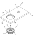
- FIG. 1 shows the external shape of a bus bar 11 formed using the caulking structure of the present invention
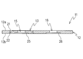
- FIGS. 2 to 7 show the form of the caulking structure portion of the bus bar 11.
- a disk-shaped conductive member 13 made of a second metal material is fitted and fixed to a flat metal plate 12 made of a first metal material.
- the metal plate 12 is formed in a flat plate shape using a copper material, which is a first metal material, and a first hole 14 is formed at a predetermined location.
- the conductive member 13 is formed in a disc shape that can be fitted into the hole portion 14 by an aluminum material that is a second metal material, and is integrally formed with a barrel portion 19 that is fitted into the hole portion 14 and an upper end of the barrel portion 19.
- a horizontal flange 22 formed integrally with the lower end.
- the horizontal flange 22 is formed in a ring shape orthogonal to the body portion 19 and is directly fitted into the lower groove portion 18 provided on the lower surface side provided around the hole portion 14 of the metal plate 12.
- the horizontal flange 22 has substantially the same shape as the lower groove portion 18 and is formed so that the width and the thickness are substantially the same, and is substantially flush with the lower surface 12b of the metal plate 12 when fitted to the lower groove portion 18. Become.
- the vertical flange 21 extends vertically along the outer peripheral surface of the body portion 19 and is fitted into the first hole portion 14 formed in the metal plate 12.
- a circular outer peripheral surface 23 protruding from the upper surface 12a side and an inner peripheral surface 24 inclined downward in a tapered shape are formed in a substantially triangular shape.
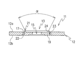
- the elevation angle ⁇ of the inner peripheral surface 24 with respect to the upper surface of the body portion 19 is set to about 60 degrees.
- the vertical flange 21 applies a constant pressing force along the inner peripheral surface 24 from above, so that the outer peripheral surface 23 is placed around the hole portion 14 of the metal plate 12 as shown in FIG. It is crushed by being spread toward the upper groove portion 17 provided on the upper surface side. As a result, the upper groove portion 17 is filled with the crushed vertical flange 21, and the conductive member 13 can be caulked and fixed in close contact with the metal plate 12.
- the vertical flange 21 is crushed, the vertical flange 21 is flush with the upper surface 12a of the metal plate 12, and can be finished to a flat surface without unevenness.
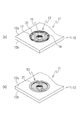
- FIG. 7A shows a state before the conductive member 13 is caulked. Then, as shown in FIG. 5, by crushing the upper portion of the vertical flange 21 protruding from the upper groove portion 17 with a pressing jig such as a punch, the inner peripheral surface 24 inclined at an elevation angle of about 60 degrees spreads outward. The upper groove portion 17 can be brought into close contact with the vertical flange 21.
- a pressing jig such as a punch
- FIG. 7 (b) the conductive member 13 is fixed to the upper surface 12a and the lower surface 12b of the metal plate 12 with each other and integrated and fixed by caulking. be able to.
- a pressing jig such as a punch is inserted along the inner peripheral surface 24 to be crushed and the outer peripheral surface 23 is spread outward, and then the upper groove portion 17 is formed using a flat pressing jig. You may make it further press toward. At the time of the first pressing, it is possible to press the tip of the punch with the inclined inner peripheral surface 24 while guiding it, so that the entire vertical flange 21 can be evenly spread.
- the bus bar 11 of the present invention is configured to form a battery pack (battery module) having a large output capacity by connecting and connecting electrode terminals of a plurality of batteries as shown in FIG. 8.
- This is a conductive connecting plate.
- the bus bar 11 includes the metal plate 12 made of the first metal material and the conductive member 13 made of the second metal material that is caulked and fixed to the metal plate 12.
- the metal plate 12 is formed in a strip-shaped flat plate shape using a highly conductive copper material, and a first hole portion 14 and a second hole portion 16 are formed at predetermined positions.
- the conductive member 13 is fitted into the first hole 14 from below, and the portion protruding from the upper surface 12a of the metal plate 12 is crushed and caulked.
- the said 2nd hole part 16 is opened as a negative electrode terminal hole for inserting directly the electrode terminal (negative electrode terminal) 34 (refer FIG. 8) of the battery cell 32 connected.
- the conductive member 13 is formed in a disk shape that can be fitted into the hole portion 14 by an aluminum material, and a positive electrode terminal for allowing the electrode terminal (positive electrode terminal) 33 (see FIG. 8) of the battery cell 32 to pass through the center portion.
- a hole 15 is opened.
- the positive electrode terminal hole 15 is a through hole, and by inserting the electrode terminal made of the same kind of aluminum material as that of the conductive member 13, conduction between dissimilar metals with the metal plate 12 made of copper material is performed. Is planned.
- the positive terminal hole 15 is opened in conformity with the diameter of the electrode terminal which varies depending on the type of battery. Further, as shown in FIGS.
- a terminal receiving portion 25 for receiving the lower end portion of the electrode terminal is formed on the lower surface of the conductive member 13 in a square shape or a circular shape centering on the positive electrode terminal hole 15.
- a recess is formed.
- the second hole 16 is electrically connected by directly inserting an electrode terminal made of the same metal material as the metal plate 12.
- a terminal receiving portion 26 for receiving the lower end portion of the electrode terminal is also formed on the lower surface of the second hole portion 16 so as to be recessed in a square shape or a circular shape.
- the metal plate 12 is formed of a copper plate having a thickness of 2 to 3 mm, and a first hole 14 having a diameter of about 17 mm and a second hole 16 having a diameter of about 6 mm are opened at a predetermined interval. ing.
- the first hole portion 14 is provided with a ring-shaped upper groove portion 17 and a lower groove portion 18 around the upper surface side and the lower surface side, respectively.
- the upper groove portion 17 and the lower groove portion 18 are formed to have a width of about 3 mm and a depth of about 0.5 mm around the first hole portion 14.
- the positive terminal hole 15 penetrating through the central portion of the body portion 19 of the conductive member 13 has the same diameter of about 6 mm as the second hole portion 16.
- the horizontal flange 22 is formed in a disc shape orthogonal to the body portion 19 and is directly fitted into the lower groove portion 18 provided in the metal plate 12. Since the horizontal flange 22 has the same shape as the lower groove portion 18 and is formed to have the same width and thickness, it is flush with the lower surface 12b of the metal plate 12.
- the joint portion of the conductive member 13 inside the metal plate 12 includes a vertical flange 21 that engages with the upper groove portion 17, and a horizontal flange 22 that engages with the lower groove portion 18. Therefore, the junction area can be widened.
- the vertical flange 21 is squeezed and fixed so as to be crushed, the body portion 19 of the conductive member 13 is closely joined to the first hole portion 14 without a gap.
- the electrical resistance at the joint between the metal plate 12 and the conductive member 13 can be greatly reduced, and the conductivity between the metal plate 12 and the conductive member 13, which are different metal materials, can be significantly improved. it can.
- the conductive member 13 is fitted in an integrated state so as to be flush with the upper surface 12a and the lower surface 12b of the metal plate 12, there is less manufacturing variation that fluctuates the electrical resistance, and the bus bar is Quality is also stable.
- one of the conductive members 13 is the horizontal flange 22 and the other is the vertical flange 21, but both flanges are formed as vertical flanges and are fixed by caulking from both the upper surface and the lower surface of the metal plate 12. It is also possible to configure as described above.
- FIG. 8 shows a configuration example of an assembled battery (battery module) 31 using the bus bar 11 of the present invention.
- the battery module 31 is formed by combining a plurality of single batteries (battery cells) 32.
- Each battery cell 32 is provided with a positive electrode terminal 33 and a negative electrode terminal 34.
- the positive electrode terminal 33 is formed of an aluminum material
- the negative electrode terminal 34 Is formed of a copper material.
- the bus-bar 11 is spanned between the positive electrode terminal 33 and the negative electrode terminal 34 of an adjacent battery cell so that the some battery cell 32 may be connected in series.
- the positive electrode terminal 33 is inserted into the positive electrode terminal hole 15 provided in the conductive member 13, and the negative electrode terminal 34 is inserted into the second hole portion 16 provided in the metal plate 12 itself. It is concluded.
- the bus bar 11 connecting the battery cells 32 can be directly electrically connected to the positive electrode terminal 33 and the negative electrode terminal 34 with the same metal material.
- the conductive member 13 made of the same kind of aluminum material as that of the positive electrode terminal 33 is incorporated into the metal plate 12 made of copper material by a main caulking structure with an increased ground surface. It has become possible to obtain good conductivity with greatly reduced resistance. This makes it suitable for power storage power sources such as hybrid vehicles and electric vehicles that require high electrical conversion efficiency, or various electric products that require power saving.
- the groove portion provided on one side of the fitting metal materials is in close contact with the flange provided on the other side by crushing.
- the joint surfaces are more firmly joined together, and the joining surface becomes a flat surface having no unevenness. For this reason, it is most suitable for the caulking structure of the portion where flatness is required.
- this caulking structure to the bus bar, even if the metal materials to be joined are different metal materials, the flange provided in the other metal material is crushed in the groove provided in one metal material.
- the electrical resistance can be reduced without a gap between the joined portions.
- the joint surface is widened in a step shape by the combination of the groove and the flange, an effect that the conductivity can be improved can be obtained.
- the caulking structure of the metal material has been described by taking the bus bar as a connecting member for constituting the battery module as an example, but the present invention is not limited to such a bus bar and can be applied to various connectors. Further, it is a caulking structure that is optimal not only for the same kind of metal materials but also for joining different kinds of metals. Therefore, the combination of the aluminum material and the copper material is not limited as in this embodiment.
Landscapes
- Chemical & Material Sciences (AREA)
- Chemical Kinetics & Catalysis (AREA)
- Electrochemistry (AREA)
- General Chemical & Material Sciences (AREA)
- Inorganic Chemistry (AREA)
- Connection Of Batteries Or Terminals (AREA)
- Connections By Means Of Piercing Elements, Nuts, Or Screws (AREA)
- Manufacturing Of Electrical Connectors (AREA)
- Connections Effected By Soldering, Adhesion, Or Permanent Deformation (AREA)
Priority Applications (4)
| Application Number | Priority Date | Filing Date | Title |
|---|---|---|---|
| CN201280040490.7A CN103733385B (zh) | 2011-09-12 | 2012-09-11 | 金属件的铆接结构及使用该铆接结构的汇流条 |
| DE112012003782.0T DE112012003782B4 (de) | 2011-09-12 | 2012-09-11 | Verpressungsstruktur für Metallelemente und Sammelschiene, welche diese verwendet |
| KR1020147003042A KR101803842B1 (ko) | 2011-09-12 | 2012-09-11 | 금속재의 스웨이징 구조 및 이 스웨이징 구조를 사용한 버스바 |
| US14/241,679 US9350088B2 (en) | 2011-09-12 | 2012-09-11 | Swaging structure for metallic members and bus bar using the same |
Applications Claiming Priority (2)
| Application Number | Priority Date | Filing Date | Title |
|---|---|---|---|
| JP2011198068A JP5699296B2 (ja) | 2011-09-12 | 2011-09-12 | 金属材のかしめ構造及びこのかしめ構造を用いたバスバー |
| JP2011-198068 | 2011-09-12 |
Publications (1)
| Publication Number | Publication Date |
|---|---|
| WO2013039043A1 true WO2013039043A1 (ja) | 2013-03-21 |
Family
ID=47883273
Family Applications (1)
| Application Number | Title | Priority Date | Filing Date |
|---|---|---|---|
| PCT/JP2012/073112 Ceased WO2013039043A1 (ja) | 2011-09-12 | 2012-09-11 | 金属材のかしめ構造及びこのかしめ構造を用いたバスバー |
Country Status (6)
| Country | Link |
|---|---|
| US (1) | US9350088B2 (enExample) |
| JP (1) | JP5699296B2 (enExample) |
| KR (1) | KR101803842B1 (enExample) |
| CN (1) | CN103733385B (enExample) |
| DE (1) | DE112012003782B4 (enExample) |
| WO (1) | WO2013039043A1 (enExample) |
Cited By (3)
| Publication number | Priority date | Publication date | Assignee | Title |
|---|---|---|---|---|
| JP2014143158A (ja) * | 2012-12-28 | 2014-08-07 | Hitachi Metals Ltd | 電極端子接続体の製造方法 |
| EP4125153A1 (en) * | 2021-07-29 | 2023-02-01 | Aptiv Technologies Limited | Bus bar assembly with plated electrical contact surface |
| US12294184B2 (en) | 2021-09-21 | 2025-05-06 | Aptiv Technologies AG | Legible confirmation of mated connection system |
Families Citing this family (29)
| Publication number | Priority date | Publication date | Assignee | Title |
|---|---|---|---|---|
| JP5582652B2 (ja) * | 2011-04-19 | 2014-09-03 | 株式会社貴匠技研 | 端子取付構造 |
| JP6082547B2 (ja) * | 2012-09-04 | 2017-02-15 | 株式会社アテックス | バスバーインサート樹脂成形品の製造方法 |
| JP2014130740A (ja) * | 2012-12-28 | 2014-07-10 | Hitachi Metals Ltd | 電極端子接続体の製造方法 |
| JP6327818B2 (ja) * | 2013-09-19 | 2018-05-23 | 株式会社貴匠技研 | コネクタ端子構造の第1端子部材 |
| JP2015082475A (ja) * | 2013-10-24 | 2015-04-27 | 東芝シュネデール・インバータ株式会社 | 接続端子と接続バーの接続構造 |
| US9748671B2 (en) * | 2014-06-16 | 2017-08-29 | Mitsubishi Electric Corporation | Terminal connection structure |
| DE102015104296A1 (de) * | 2015-03-23 | 2016-09-29 | Auto-Kabel Management Gmbh | Zellverbinder sowie System mit einem Zellverbinder |
| JP6568721B2 (ja) * | 2015-05-29 | 2019-08-28 | 株式会社貴匠技研 | コネクタ端子及びこのコネクタ端子を用いたバスバー |
| CN106784562B (zh) * | 2016-12-13 | 2023-01-06 | 芜湖天量电池系统有限公司 | 一种锂电池的电连接组件 |
| JP6765339B2 (ja) * | 2017-04-24 | 2020-10-07 | キヤノン・コンポーネンツ株式会社 | イメージセンサユニット、紙葉類識別装置、読取装置および画像形成装置 |
| CN107327646A (zh) * | 2017-05-27 | 2017-11-07 | 苏州吉利不锈钢制品有限公司 | 一种汇流块结构 |
| JP2019008876A (ja) * | 2017-06-20 | 2019-01-17 | 矢崎総業株式会社 | バスバユニット及び導電モジュール |
| CN107195810A (zh) * | 2017-07-06 | 2017-09-22 | 池州市骏智机电科技有限公司 | 一种动力电池顶盖 |
| CN107248555B (zh) * | 2017-07-06 | 2022-04-15 | 池州市骏智机电科技有限公司 | 一种动力电池顶盖的加工工艺 |
| CN108832447B (zh) * | 2018-06-29 | 2020-12-08 | 常州博瑞电力自动化设备有限公司 | 一种铜排无钉平整铆接结构及其工艺方法 |
| EP3719932B1 (de) * | 2019-04-05 | 2022-10-05 | Intercable Automotive Solutions GmbH | Stromverbinder, herstellungsverfahren und elektrische verbindungsanordnung |
| JP7028825B2 (ja) * | 2019-05-22 | 2022-03-02 | 本田技研工業株式会社 | 組電池 |
| JP6904379B2 (ja) * | 2019-06-10 | 2021-07-14 | Smk株式会社 | 電気接続構造体、電気接続方法、電気コネクタ及び電気装置 |
| KR102213623B1 (ko) * | 2020-07-21 | 2021-02-08 | 대산전자(주) | 접합 보강력이 향상된 버스바 및 이의 제조방법 |
| US12114426B2 (en) | 2020-09-30 | 2024-10-08 | Inventus Power, Inc. | Conformal wearable battery and system |
| US11477885B2 (en) | 2020-09-30 | 2022-10-18 | Inventus Power, Inc. | Redundant trace fuse for a conformal wearable battery |
| US11349174B2 (en) | 2020-09-30 | 2022-05-31 | Inventus Power, Inc. | Flexible battery matrix for a conformal wearable battery |
| US11251497B1 (en) | 2020-09-30 | 2022-02-15 | Inventus Power, Inc. | Conformal wearable battery |
| US11394077B1 (en) | 2021-03-15 | 2022-07-19 | Inventus Power, Inc. | Conformal wearable battery |
| DE102021113768A1 (de) | 2021-05-27 | 2022-12-01 | Te Connectivity Germany Gmbh | Kontaktanordnung mit reibschlüssig gefügtem Kontaktelement sowie Modulverbinder, Verbindungsanordnung, Batteriezelle und Batteriemodul mit solchen Kontaktanordnungen |
| US11581607B1 (en) | 2021-09-30 | 2023-02-14 | Inventus Power, Inc. | Thermal management for a conformal wearable battery |
| JP7583761B2 (ja) * | 2022-04-25 | 2024-11-14 | プライムプラネットエナジー&ソリューションズ株式会社 | バスバー及びそれを備えた組電池 |
| KR20240099611A (ko) | 2022-12-22 | 2024-07-01 | 이엠코리아주식회사 | 스웨이징 공구 |
| CN219419246U (zh) * | 2023-04-07 | 2023-07-25 | 远景动力技术(江苏)有限公司 | 顶盖及包含其的电池和电子设备 |
Citations (3)
| Publication number | Priority date | Publication date | Assignee | Title |
|---|---|---|---|---|
| JP2004039256A (ja) * | 2002-06-28 | 2004-02-05 | Meidensha Corp | 積層導体の端子接続構造 |
| WO2009096013A1 (ja) * | 2008-01-30 | 2009-08-06 | Mitsubishi Electric Corporation | 端子接合構造及び端子接合方法 |
| WO2012102160A1 (ja) * | 2011-01-27 | 2012-08-02 | 株式会社Neomaxマテリアル | 電池端子用接続板および電池端子用接続板の製造方法 |
Family Cites Families (22)
| Publication number | Priority date | Publication date | Assignee | Title |
|---|---|---|---|---|
| JPS4710864Y1 (enExample) * | 1968-05-15 | 1972-04-21 | ||
| JPS5413473A (en) * | 1977-02-17 | 1979-01-31 | Kurorin Engineers Kk | Double polar electrode |
| JPS5569913A (en) * | 1979-10-16 | 1980-05-27 | Matsushita Electric Works Ltd | Method of manufacturing contactor |
| JPS59815Y2 (ja) | 1979-10-29 | 1984-01-11 | 横河電機株式会社 | 電圧・電流変換回路 |
| JPS59815A (ja) * | 1982-06-28 | 1984-01-06 | 田中貴金属工業株式会社 | 電気接触子の製造方法 |
| JPS6050823A (ja) * | 1983-08-31 | 1985-03-20 | 松下電工株式会社 | 接点の加工法 |
| JPS6273583A (ja) * | 1985-09-26 | 1987-04-04 | 株式会社東芝 | 端子の取付方法 |
| JPS63194311A (ja) * | 1987-02-09 | 1988-08-11 | アルプス電気株式会社 | 電子部品の鳩目構造とその製造方法 |
| JPH076096B2 (ja) | 1990-12-26 | 1995-01-25 | 長利 藤本 | 複合繊維の製造法 |
| JP3058201B2 (ja) * | 1991-06-17 | 2000-07-04 | 田中貴金属工業株式会社 | 電気接点の製造方法 |
| JP4201301B2 (ja) * | 2000-01-24 | 2008-12-24 | Necトーキン株式会社 | 密閉型電池 |
| JP2002358945A (ja) * | 2000-11-15 | 2002-12-13 | Ngk Insulators Ltd | リチウム二次単電池の接続構造体 |
| US6542372B1 (en) * | 2001-09-25 | 2003-04-01 | Hewlett-Packard Development Company, L.P. | Chassis-mounted bumper for a circuit board |
| CN101255885B (zh) * | 2007-03-01 | 2011-03-30 | 鸿富锦精密工业(深圳)有限公司 | 紧固装置 |
| US8119280B2 (en) * | 2007-06-07 | 2012-02-21 | A123 Systems, Inc. | Cap assembly for a high current capacity energy delivery device |
| FR2922370B1 (fr) | 2007-10-15 | 2009-11-20 | Eldre | Borne de connexion electrique. |
| JP5595830B2 (ja) * | 2009-08-26 | 2014-09-24 | 株式会社東芝 | 電池、組電池及び組電池の製造方法 |
| JP5528746B2 (ja) | 2009-09-11 | 2014-06-25 | 三洋電機株式会社 | 組電池 |
| JP5449961B2 (ja) * | 2009-09-30 | 2014-03-19 | 三洋電機株式会社 | 二次電池 |
| US9196890B2 (en) * | 2009-10-05 | 2015-11-24 | Samsung Sdi Co., Ltd. | Battery module with welded portion between terminals |
| DE102009054476A1 (de) * | 2009-12-10 | 2011-06-16 | SB LiMotive Company Ltd., Suwon | Verbindungselement |
| EP2478957A1 (en) | 2011-01-25 | 2012-07-25 | Norit Nederland B.V. | Production of catalytically active activated carbon |
-
2011
- 2011-09-12 JP JP2011198068A patent/JP5699296B2/ja active Active
-
2012
- 2012-09-11 US US14/241,679 patent/US9350088B2/en active Active
- 2012-09-11 WO PCT/JP2012/073112 patent/WO2013039043A1/ja not_active Ceased
- 2012-09-11 KR KR1020147003042A patent/KR101803842B1/ko active Active
- 2012-09-11 DE DE112012003782.0T patent/DE112012003782B4/de active Active
- 2012-09-11 CN CN201280040490.7A patent/CN103733385B/zh active Active
Patent Citations (3)
| Publication number | Priority date | Publication date | Assignee | Title |
|---|---|---|---|---|
| JP2004039256A (ja) * | 2002-06-28 | 2004-02-05 | Meidensha Corp | 積層導体の端子接続構造 |
| WO2009096013A1 (ja) * | 2008-01-30 | 2009-08-06 | Mitsubishi Electric Corporation | 端子接合構造及び端子接合方法 |
| WO2012102160A1 (ja) * | 2011-01-27 | 2012-08-02 | 株式会社Neomaxマテリアル | 電池端子用接続板および電池端子用接続板の製造方法 |
Cited By (4)
| Publication number | Priority date | Publication date | Assignee | Title |
|---|---|---|---|---|
| JP2014143158A (ja) * | 2012-12-28 | 2014-08-07 | Hitachi Metals Ltd | 電極端子接続体の製造方法 |
| EP4125153A1 (en) * | 2021-07-29 | 2023-02-01 | Aptiv Technologies Limited | Bus bar assembly with plated electrical contact surface |
| US12237658B2 (en) | 2021-07-29 | 2025-02-25 | Aptiv Technologies AG | Bus bar assembly with plated electrical contact surface |
| US12294184B2 (en) | 2021-09-21 | 2025-05-06 | Aptiv Technologies AG | Legible confirmation of mated connection system |
Also Published As
| Publication number | Publication date |
|---|---|
| KR101803842B1 (ko) | 2017-12-04 |
| KR20140060494A (ko) | 2014-05-20 |
| DE112012003782B4 (de) | 2024-01-25 |
| JP2013062045A (ja) | 2013-04-04 |
| US9350088B2 (en) | 2016-05-24 |
| DE112012003782T5 (de) | 2014-06-18 |
| JP5699296B2 (ja) | 2015-04-08 |
| CN103733385A (zh) | 2014-04-16 |
| CN103733385B (zh) | 2016-05-04 |
| US20140216814A1 (en) | 2014-08-07 |
Similar Documents
| Publication | Publication Date | Title |
|---|---|---|
| JP5699296B2 (ja) | 金属材のかしめ構造及びこのかしめ構造を用いたバスバー | |
| JP5528746B2 (ja) | 組電池 | |
| KR100778511B1 (ko) | 이차 전지 모듈 | |
| US12074345B2 (en) | Terminal, secondary battery provided with same, and methods for producing same | |
| US10135040B2 (en) | Electric storage device, electric storage device assembly, and method for producing electric storage device | |
| US8906545B2 (en) | Prismatic secondary battery | |
| US20130260611A1 (en) | Battery module | |
| JP5628127B2 (ja) | 二次電池 | |
| US20100081048A1 (en) | Prismatic secondary battery and battery module thereof | |
| KR101746442B1 (ko) | 단자 부착 구조 | |
| JP2017526130A (ja) | バッテリモジュールのための収容器、及び、このような収容器を有するバッテリモジュール | |
| JP2013536979A (ja) | 抵抗溶接によるセルタブ連結構造を有するバッテリー | |
| JP2005322648A (ja) | 二次電池モジュール | |
| KR101072954B1 (ko) | 이차전지 모듈 | |
| KR20140096664A (ko) | 이차전지 | |
| US12230814B2 (en) | Rectangular secondary battery and assembled battery including the same | |
| US8969727B2 (en) | Battery module | |
| JP2016092005A (ja) | 蓄電装置及び蓄電装置の製造方法 | |
| KR100669436B1 (ko) | 이차 전지 모듈 | |
| JP5440663B2 (ja) | 電池 | |
| JP6568721B2 (ja) | コネクタ端子及びこのコネクタ端子を用いたバスバー | |
| JP2006040771A (ja) | 捲回式電池 | |
| KR20170077536A (ko) | 배터리 팩 | |
| JP2017054628A (ja) | 蓄電素子 |
Legal Events
| Date | Code | Title | Description |
|---|---|---|---|
| WWE | Wipo information: entry into national phase |
Ref document number: 201280040490.7 Country of ref document: CN |
|
| 121 | Ep: the epo has been informed by wipo that ep was designated in this application |
Ref document number: 12832074 Country of ref document: EP Kind code of ref document: A1 |
|
| ENP | Entry into the national phase |
Ref document number: 20147003042 Country of ref document: KR Kind code of ref document: A |
|
| WWE | Wipo information: entry into national phase |
Ref document number: 14241679 Country of ref document: US |
|
| WWE | Wipo information: entry into national phase |
Ref document number: 1120120037820 Country of ref document: DE Ref document number: 112012003782 Country of ref document: DE |
|
| 122 | Ep: pct application non-entry in european phase |
Ref document number: 12832074 Country of ref document: EP Kind code of ref document: A1 |