WO2013035673A1 - 充電ケーブルの中間把持具 - Google Patents
充電ケーブルの中間把持具 Download PDFInfo
- Publication number
- WO2013035673A1 WO2013035673A1 PCT/JP2012/072376 JP2012072376W WO2013035673A1 WO 2013035673 A1 WO2013035673 A1 WO 2013035673A1 JP 2012072376 W JP2012072376 W JP 2012072376W WO 2013035673 A1 WO2013035673 A1 WO 2013035673A1
- Authority
- WO
- WIPO (PCT)
- Prior art keywords
- charging
- charging cable
- gripping tool
- intermediate gripping
- cylindrical portion
- Prior art date
- Legal status (The legal status is an assumption and is not a legal conclusion. Google has not performed a legal analysis and makes no representation as to the accuracy of the status listed.)
- Ceased
Links
Images


Classifications
-
- F—MECHANICAL ENGINEERING; LIGHTING; HEATING; WEAPONS; BLASTING
- F16—ENGINEERING ELEMENTS AND UNITS; GENERAL MEASURES FOR PRODUCING AND MAINTAINING EFFECTIVE FUNCTIONING OF MACHINES OR INSTALLATIONS; THERMAL INSULATION IN GENERAL
- F16L—PIPES; JOINTS OR FITTINGS FOR PIPES; SUPPORTS FOR PIPES, CABLES OR PROTECTIVE TUBING; MEANS FOR THERMAL INSULATION IN GENERAL
- F16L3/00—Supports for pipes, cables or protective tubing, e.g. hangers, holders, clamps, cleats, clips, brackets
- F16L3/01—Supports for pipes, cables or protective tubing, e.g. hangers, holders, clamps, cleats, clips, brackets for supporting or guiding the pipes, cables or protective tubing, between relatively movable points, e.g. movable channels
-
- B—PERFORMING OPERATIONS; TRANSPORTING
- B60—VEHICLES IN GENERAL
- B60L—PROPULSION OF ELECTRICALLY-PROPELLED VEHICLES; SUPPLYING ELECTRIC POWER FOR AUXILIARY EQUIPMENT OF ELECTRICALLY-PROPELLED VEHICLES; ELECTRODYNAMIC BRAKE SYSTEMS FOR VEHICLES IN GENERAL; MAGNETIC SUSPENSION OR LEVITATION FOR VEHICLES; MONITORING OPERATING VARIABLES OF ELECTRICALLY-PROPELLED VEHICLES; ELECTRIC SAFETY DEVICES FOR ELECTRICALLY-PROPELLED VEHICLES
- B60L53/00—Methods of charging batteries, specially adapted for electric vehicles; Charging stations or on-board charging equipment therefor; Exchange of energy storage elements in electric vehicles
- B60L53/10—Methods of charging batteries, specially adapted for electric vehicles; Charging stations or on-board charging equipment therefor; Exchange of energy storage elements in electric vehicles characterised by the energy transfer between the charging station and the vehicle
- B60L53/14—Conductive energy transfer
- B60L53/16—Connectors, e.g. plugs or sockets, specially adapted for charging electric vehicles
-
- B—PERFORMING OPERATIONS; TRANSPORTING
- B60—VEHICLES IN GENERAL
- B60L—PROPULSION OF ELECTRICALLY-PROPELLED VEHICLES; SUPPLYING ELECTRIC POWER FOR AUXILIARY EQUIPMENT OF ELECTRICALLY-PROPELLED VEHICLES; ELECTRODYNAMIC BRAKE SYSTEMS FOR VEHICLES IN GENERAL; MAGNETIC SUSPENSION OR LEVITATION FOR VEHICLES; MONITORING OPERATING VARIABLES OF ELECTRICALLY-PROPELLED VEHICLES; ELECTRIC SAFETY DEVICES FOR ELECTRICALLY-PROPELLED VEHICLES
- B60L53/00—Methods of charging batteries, specially adapted for electric vehicles; Charging stations or on-board charging equipment therefor; Exchange of energy storage elements in electric vehicles
- B60L53/10—Methods of charging batteries, specially adapted for electric vehicles; Charging stations or on-board charging equipment therefor; Exchange of energy storage elements in electric vehicles characterised by the energy transfer between the charging station and the vehicle
- B60L53/14—Conductive energy transfer
- B60L53/18—Cables specially adapted for charging electric vehicles
-
- B—PERFORMING OPERATIONS; TRANSPORTING
- B60—VEHICLES IN GENERAL
- B60L—PROPULSION OF ELECTRICALLY-PROPELLED VEHICLES; SUPPLYING ELECTRIC POWER FOR AUXILIARY EQUIPMENT OF ELECTRICALLY-PROPELLED VEHICLES; ELECTRODYNAMIC BRAKE SYSTEMS FOR VEHICLES IN GENERAL; MAGNETIC SUSPENSION OR LEVITATION FOR VEHICLES; MONITORING OPERATING VARIABLES OF ELECTRICALLY-PROPELLED VEHICLES; ELECTRIC SAFETY DEVICES FOR ELECTRICALLY-PROPELLED VEHICLES
- B60L53/00—Methods of charging batteries, specially adapted for electric vehicles; Charging stations or on-board charging equipment therefor; Exchange of energy storage elements in electric vehicles
- B60L53/30—Constructional details of charging stations
- B60L53/31—Charging columns specially adapted for electric vehicles
-
- B—PERFORMING OPERATIONS; TRANSPORTING
- B60—VEHICLES IN GENERAL
- B60L—PROPULSION OF ELECTRICALLY-PROPELLED VEHICLES; SUPPLYING ELECTRIC POWER FOR AUXILIARY EQUIPMENT OF ELECTRICALLY-PROPELLED VEHICLES; ELECTRODYNAMIC BRAKE SYSTEMS FOR VEHICLES IN GENERAL; MAGNETIC SUSPENSION OR LEVITATION FOR VEHICLES; MONITORING OPERATING VARIABLES OF ELECTRICALLY-PROPELLED VEHICLES; ELECTRIC SAFETY DEVICES FOR ELECTRICALLY-PROPELLED VEHICLES
- B60L2210/00—Converter types
- B60L2210/10—DC to DC converters
-
- B—PERFORMING OPERATIONS; TRANSPORTING
- B60—VEHICLES IN GENERAL
- B60L—PROPULSION OF ELECTRICALLY-PROPELLED VEHICLES; SUPPLYING ELECTRIC POWER FOR AUXILIARY EQUIPMENT OF ELECTRICALLY-PROPELLED VEHICLES; ELECTRODYNAMIC BRAKE SYSTEMS FOR VEHICLES IN GENERAL; MAGNETIC SUSPENSION OR LEVITATION FOR VEHICLES; MONITORING OPERATING VARIABLES OF ELECTRICALLY-PROPELLED VEHICLES; ELECTRIC SAFETY DEVICES FOR ELECTRICALLY-PROPELLED VEHICLES
- B60L2210/00—Converter types
- B60L2210/30—AC to DC converters
-
- B—PERFORMING OPERATIONS; TRANSPORTING
- B60—VEHICLES IN GENERAL
- B60L—PROPULSION OF ELECTRICALLY-PROPELLED VEHICLES; SUPPLYING ELECTRIC POWER FOR AUXILIARY EQUIPMENT OF ELECTRICALLY-PROPELLED VEHICLES; ELECTRODYNAMIC BRAKE SYSTEMS FOR VEHICLES IN GENERAL; MAGNETIC SUSPENSION OR LEVITATION FOR VEHICLES; MONITORING OPERATING VARIABLES OF ELECTRICALLY-PROPELLED VEHICLES; ELECTRIC SAFETY DEVICES FOR ELECTRICALLY-PROPELLED VEHICLES
- B60L2270/00—Problem solutions or means not otherwise provided for
- B60L2270/30—Preventing theft during charging
- B60L2270/32—Preventing theft during charging of electricity
-
- B—PERFORMING OPERATIONS; TRANSPORTING
- B60—VEHICLES IN GENERAL
- B60L—PROPULSION OF ELECTRICALLY-PROPELLED VEHICLES; SUPPLYING ELECTRIC POWER FOR AUXILIARY EQUIPMENT OF ELECTRICALLY-PROPELLED VEHICLES; ELECTRODYNAMIC BRAKE SYSTEMS FOR VEHICLES IN GENERAL; MAGNETIC SUSPENSION OR LEVITATION FOR VEHICLES; MONITORING OPERATING VARIABLES OF ELECTRICALLY-PROPELLED VEHICLES; ELECTRIC SAFETY DEVICES FOR ELECTRICALLY-PROPELLED VEHICLES
- B60L2270/00—Problem solutions or means not otherwise provided for
- B60L2270/30—Preventing theft during charging
- B60L2270/34—Preventing theft during charging of parts
-
- Y—GENERAL TAGGING OF NEW TECHNOLOGICAL DEVELOPMENTS; GENERAL TAGGING OF CROSS-SECTIONAL TECHNOLOGIES SPANNING OVER SEVERAL SECTIONS OF THE IPC; TECHNICAL SUBJECTS COVERED BY FORMER USPC CROSS-REFERENCE ART COLLECTIONS [XRACs] AND DIGESTS
- Y02—TECHNOLOGIES OR APPLICATIONS FOR MITIGATION OR ADAPTATION AGAINST CLIMATE CHANGE
- Y02T—CLIMATE CHANGE MITIGATION TECHNOLOGIES RELATED TO TRANSPORTATION
- Y02T10/00—Road transport of goods or passengers
- Y02T10/60—Other road transportation technologies with climate change mitigation effect
- Y02T10/70—Energy storage systems for electromobility, e.g. batteries
-
- Y—GENERAL TAGGING OF NEW TECHNOLOGICAL DEVELOPMENTS; GENERAL TAGGING OF CROSS-SECTIONAL TECHNOLOGIES SPANNING OVER SEVERAL SECTIONS OF THE IPC; TECHNICAL SUBJECTS COVERED BY FORMER USPC CROSS-REFERENCE ART COLLECTIONS [XRACs] AND DIGESTS
- Y02—TECHNOLOGIES OR APPLICATIONS FOR MITIGATION OR ADAPTATION AGAINST CLIMATE CHANGE
- Y02T—CLIMATE CHANGE MITIGATION TECHNOLOGIES RELATED TO TRANSPORTATION
- Y02T10/00—Road transport of goods or passengers
- Y02T10/60—Other road transportation technologies with climate change mitigation effect
- Y02T10/7072—Electromobility specific charging systems or methods for batteries, ultracapacitors, supercapacitors or double-layer capacitors
-
- Y—GENERAL TAGGING OF NEW TECHNOLOGICAL DEVELOPMENTS; GENERAL TAGGING OF CROSS-SECTIONAL TECHNOLOGIES SPANNING OVER SEVERAL SECTIONS OF THE IPC; TECHNICAL SUBJECTS COVERED BY FORMER USPC CROSS-REFERENCE ART COLLECTIONS [XRACs] AND DIGESTS
- Y02—TECHNOLOGIES OR APPLICATIONS FOR MITIGATION OR ADAPTATION AGAINST CLIMATE CHANGE
- Y02T—CLIMATE CHANGE MITIGATION TECHNOLOGIES RELATED TO TRANSPORTATION
- Y02T10/00—Road transport of goods or passengers
- Y02T10/60—Other road transportation technologies with climate change mitigation effect
- Y02T10/72—Electric energy management in electromobility
-
- Y—GENERAL TAGGING OF NEW TECHNOLOGICAL DEVELOPMENTS; GENERAL TAGGING OF CROSS-SECTIONAL TECHNOLOGIES SPANNING OVER SEVERAL SECTIONS OF THE IPC; TECHNICAL SUBJECTS COVERED BY FORMER USPC CROSS-REFERENCE ART COLLECTIONS [XRACs] AND DIGESTS
- Y02—TECHNOLOGIES OR APPLICATIONS FOR MITIGATION OR ADAPTATION AGAINST CLIMATE CHANGE
- Y02T—CLIMATE CHANGE MITIGATION TECHNOLOGIES RELATED TO TRANSPORTATION
- Y02T90/00—Enabling technologies or technologies with a potential or indirect contribution to GHG emissions mitigation
- Y02T90/10—Technologies relating to charging of electric vehicles
- Y02T90/12—Electric charging stations
-
- Y—GENERAL TAGGING OF NEW TECHNOLOGICAL DEVELOPMENTS; GENERAL TAGGING OF CROSS-SECTIONAL TECHNOLOGIES SPANNING OVER SEVERAL SECTIONS OF THE IPC; TECHNICAL SUBJECTS COVERED BY FORMER USPC CROSS-REFERENCE ART COLLECTIONS [XRACs] AND DIGESTS
- Y02—TECHNOLOGIES OR APPLICATIONS FOR MITIGATION OR ADAPTATION AGAINST CLIMATE CHANGE
- Y02T—CLIMATE CHANGE MITIGATION TECHNOLOGIES RELATED TO TRANSPORTATION
- Y02T90/00—Enabling technologies or technologies with a potential or indirect contribution to GHG emissions mitigation
- Y02T90/10—Technologies relating to charging of electric vehicles
- Y02T90/14—Plug-in electric vehicles
Definitions
- the present invention relates to an intermediate gripping tool for a charging cable that is attached in the middle of a charging cable of a charging stand.
- a charging stand for charging a battery of an electric vehicle usually has a charging cable pulled out from the casing, and a plug is provided at the tip of the charging cable.
- Patent Document 1 discloses a charging operation for a battery in which a user holds the plug, that is, a charging connector and inserts the plug into a power supply insertion port of an electric vehicle.
- the charging cable is required to have a voltage resistance and strength that can cope with such a large electric power. For this reason, charging cables that satisfy such requirements tend to be thick, hard, and heavy cables, which has been a cause of impairing operability during charging.
- the present invention has been made to solve the above problems. And the objective is to provide the intermediate holding tool of the charging cable from which the operativity at the time of charge becomes favorable.
- the present invention is an intermediate gripping tool for a charging cable attached to a charging cable extending from a charging stand.
- gripping tool is provided so that it may penetrate by a charging cable, and is provided with the cylinder part latched by the hook provided in the charging stand.
- the grip part extended from the cylinder part and gripped is provided.
- FIG. 1 is a diagram illustrating a state in which a vehicle battery is charged from a charging stand by applying an intermediate gripping tool for a charging cable according to an embodiment of the present invention.
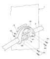
- FIG. 2 is a perspective view showing a state where the intermediate gripping tool of the charging cable of FIG. 1 is hooked on the hook of the charging stand.
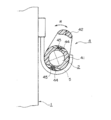
- FIG. 3 is a longitudinal sectional view of an essential part of FIG.
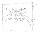
- FIG. 4 is a perspective view showing a state in which the intermediate gripping tool of the charging cable of FIG. 1 is hooked on the hook of another charging stand.
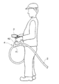
- FIG. 5 is a diagram illustrating a state when charging is performed using the intermediate gripping tool of the charging cable according to the embodiment of the present invention.
- FIG. 6 is another view showing a state when charging is performed using the intermediate gripping tool of the charging cable according to the embodiment of the present invention.
- an intermediate gripping tool 4 for a charging cable is for attaching to the charging cable 2 to perform a charging operation.
- the charging stand 1 incorporates a power conversion circuit that converts commercial AC power into DC power and boosts it to a predetermined voltage. Further, from the charging stand 1, the charging cable 2 is drawn out from the side surface of the housing installed at the power feeding place.
- the intermediate gripping tool 4 of the charging cable may be simply abbreviated as “intermediate gripping tool 4”.
- the charging cable 2 is a power supply cable that supplies the DC power converted by the charging stand 1 to the battery of the electric vehicle V via the charging connector 3 provided at the tip thereof.
- the charging cable 2 is configured by covering an electric wire with an insulating material such as rubber. At the time of charging, charging is started by attaching the charging connector 3 to the power supply inlet V1 of the electric vehicle V and pressing a charging start button or the like provided on the charging stand 1.
- the charging cable 2 has a sufficient length so as to reach the power supply inlet V1 of the electric vehicle V parked near the charging stand 1. For example, a length of about 10 m is common. And at the time of non-charging, the charging cable 2 can be wound, for example in a spiral shape so that the charging cable 2 does not get in the way.
- the charging connector 3 is stored in a predetermined part provided on the front surface of the casing of the charging stand 1.
- the intermediate gripping tool 4 of this embodiment is attached to the charging cable 2 extending from the charging stand 1. And it is provided with the cylinder part 41 which is formed so that it may penetrate by the charging cable 2, and is hooked by the hook 5 provided in the said charging stand 1 in hook shape. Furthermore, the grip part 42 extended from the cylinder part 41 and hold
- the intermediate gripping tool 4 can be made of an insulating material such as plastic, for example. Then, for example, as shown in FIG. 2, it is possible to combine the members that are divided in the left and right with respect to the axial direction of the charging cable 2. That is, as shown in FIGS. 2 and 3, the member divided in half so that the cylindrical portion 41 covers and penetrates the charging cable 2 can be fixed using the bolt 44 and the nut 45. In this way, the intermediate gripping tool 4 can be attached to the charging cable 2.
- the present invention is not limited to such a mode, and when the intermediate gripping tool 4 is mounted on the charging cable 2, it can be mounted in a conventionally known mode.
- the frictional force (pressing force) and the portion deformed by the frictional force (pressing force) work.
- the threshold value of the frictional force that leads to such a state depends on both surface characteristics such as the elasticity of the surface of the cylindrical portion 41 and the charging cable 2 and the friction coefficient.
- the tightening force between the bolt 44 and the nut 45 can be determined in consideration of the surface characteristics of the cylinder portion 41 and the charging cable 2.
- the cylinder part 41 is rotatable around the axis of the charging cable 2 even when the movement of the cylinder part 41 in the axial direction of the charging cable 2 is restricted.
- the cylindrical portion 41 is rotatable, so that the gripping portion 42 is inclined toward the opposite side of the charging stand 1 with respect to the hook 5 and the intermediate gripping is performed.
- the tool 4 can be hooked on the hook 5.
- the charging operator can easily grip the grip portion 42 when performing the charging operation next time.
- the tightening force between the bolt 44 and the nut 45 is adjusted in consideration of the surface characteristics of the tube portion 41 and the charging cable 2 as described above. do it.
- annular concavo-convex portion 43 that is engaged with the hook 5 when the cylindrical portion 41 is hooked on the hook 5 is provided on the outer peripheral surface of the cylindrical portion 41.
- the “annular irregularities” are irregularities formed on the surface of the cylindrical portion, and the irregularities are formed in the axial direction of the cylindrical portion, and the concave portion and the convex portion are respectively in the circumferential direction of the cylindrical portion. It means the shape that is connected along.
- the annular concavo-convex portion 43 prevents the cylindrical portion 41 from sliding to the hook 5 and can stabilize the cylindrical portion 41. Furthermore, in the cylinder part 41, it is good also as a thing provided with multiple annular uneven
- FIG. 2 shows an example in which only one hook 5 is provided
- FIG. 4 shows an example in which two hooks 5 spaced apart from each other are arranged.
- FIG. 4 shows an example of a plurality of annular concavo-convex portions 43 that engage with the hooks 5 and 5 respectively.
- the number is not limited to two and may be two or more.
- the grip portion 42 has a shape that can be gripped by a charging worker in a state where the tube portion 41 is hooked on the hook 5.
- the shape extends from the both ends of the tubular portion 41 to the upper portion, but is not limited thereto. That is, the shape may be a shape that can be held by the charging worker and can be hooked on the hook.
- the shape may be a cantilever shape that extends upward from one end of the cylindrical portion 41.
- the charging connector 3 provided at the tip of the charging cable 2 can be stored in a predetermined part provided in the front of the charging stand 1.
- the tubular portion 41 of the intermediate gripping tool 4 attached to the charging cable 2 can be hooked on the hook 5 provided on the side surface of the charging stand 1 so that the charging cable 2 is wound in a spiral shape. .
- the charging connector 3 When charging is started, the charging connector 3 can be detached from a predetermined portion with one hand, the grip portion 42 of the intermediate gripping tool 4 can be gripped with the other hand, and the tube portion 41 can be detached from the hook 5. Thereby, the charging worker can hold the tip of the charging cable with one hand and the charging cable with the other hand.
- the charging cable 2 through which high power flows at a high voltage is required to have voltage resistance and strength corresponding to the charging cable 2. For this reason, charging cables that satisfy such requirements tend to be thick, hard, and heavy cables.
- the intermediate gripping tool 4 of the present embodiment the charging cable 2 can be efficiently gripped with both hands. Therefore, the operation of attaching the charging connector 3 to the power supply inlet V1 of the electric vehicle V becomes easy. Further, even when the charging cable 2 is wound in a spiral shape, the charging cable 2 can be held by the intermediate gripping tool 4, so that the twist can be easily eliminated.
- the charging operator himself / herself rotates and extends while eliminating the twisting of the charging cable 2, and the charging connector 3 is attached to the feeding inlet V 1 of the electric vehicle V. After that, the intermediate gripping tool 4 is released from the hand, and the charging start button provided on the charging stand 1 is pressed to start the charging process.
- the charging operator holds the charging connector 3 with one hand and holds the grip portion 42 of the intermediate holding tool 4 with the other hand. Then, after the charging connector 3 is removed from the power supply inlet V1, the charging connector 3 is housed in a predetermined portion of the charging stand 1 while the charging cable 2 is wound again in a spiral shape, and the cylindrical portion 41 of the intermediate gripping tool 4 is hooked 5 Hang on.
- the intermediate gripping tool 4 As described above, by attaching the intermediate gripping tool 4 according to the present embodiment, even if the charging cable 2 is thick, hard, and heavy, its handling workability and operability are improved, and it is a weak charging worker. However, the charging operation can be easily performed. Further, at the time of non-charging, the charging cable 2 can be wound in a spiral shape so that the cylindrical portion 41 of the intermediate gripping tool 4 can be hooked on the hook 5, so that it is possible to prevent the charging cable 2 from getting on the ground and becoming dirty.
- the cylindrical portion 41 of the intermediate gripping tool 4 includes an annular uneven portion 43 that is engaged with the hook 5 when the cylindrical portion 41 is hooked on the hook 5. Therefore, even if some external force acts on the charging cable 2 during non-charging, it can be prevented from easily falling off the hook 5. That is, the stability when the intermediate gripping tool 4 is hooked on the hook 5 is improved.
- the plurality of annular concavo-convex portions 43, 43 are arranged so as to be engaged with the plurality of hooks 5, 5 provided on the charging stand with a space between each other. Sex becomes more remarkable.
- the cylindrical portion 41 of the intermediate gripping tool 4 can be rotated around the axis of the charging cable 2 by adjusting the tightening degree of the bolt 44 and the nut 45. Therefore, when the intermediate gripping tool 4 is hooked on the hook 5, the cylindrical portion 41 can be rotated to the right side of the arrow R in FIG. In this way, the charging operator can easily grip the grip portion 42 when performing the charging operation next time.
- the charging operation can be performed while gripping the intermediate gripping tool of the charging cable with the hand not holding the charging connector.
- the operability during charging can be improved.
- Charging stand 2 Charging cable 3 Charging connector 4 Charging cable intermediate gripping tool (intermediate gripping tool) 5 Hook 41 Cylindrical part 42 Grip part 43 Annular uneven part 44 Bolt 45 Nut V Electric vehicle V1 Feed inlet
Landscapes
- Engineering & Computer Science (AREA)
- Mechanical Engineering (AREA)
- Power Engineering (AREA)
- Transportation (AREA)
- General Engineering & Computer Science (AREA)
- Electric Propulsion And Braking For Vehicles (AREA)
- Charge And Discharge Circuits For Batteries Or The Like (AREA)
Priority Applications (3)
| Application Number | Priority Date | Filing Date | Title |
|---|---|---|---|
| EP12829894.0A EP2755295B1 (en) | 2011-09-11 | 2012-09-03 | Intermediate grasping tool of charging cable |
| US14/343,874 US10072774B2 (en) | 2011-09-11 | 2012-09-03 | Intermediate grasping tool of charging cable |
| CN201280042969.4A CN103782473B (zh) | 2011-09-11 | 2012-09-03 | 充电线缆的中间把持件 |
Applications Claiming Priority (2)
| Application Number | Priority Date | Filing Date | Title |
|---|---|---|---|
| JP2011-197763 | 2011-09-11 | ||
| JP2011197763A JP5392327B2 (ja) | 2011-09-11 | 2011-09-11 | 充電ケーブルの中間把持具 |
Publications (1)
| Publication Number | Publication Date |
|---|---|
| WO2013035673A1 true WO2013035673A1 (ja) | 2013-03-14 |
Family
ID=47832118
Family Applications (1)
| Application Number | Title | Priority Date | Filing Date |
|---|---|---|---|
| PCT/JP2012/072376 Ceased WO2013035673A1 (ja) | 2011-09-11 | 2012-09-03 | 充電ケーブルの中間把持具 |
Country Status (5)
| Country | Link |
|---|---|
| US (1) | US10072774B2 (enExample) |
| EP (1) | EP2755295B1 (enExample) |
| JP (1) | JP5392327B2 (enExample) |
| CN (1) | CN103782473B (enExample) |
| WO (1) | WO2013035673A1 (enExample) |
Families Citing this family (7)
| Publication number | Priority date | Publication date | Assignee | Title |
|---|---|---|---|---|
| JP2013179756A (ja) * | 2012-02-28 | 2013-09-09 | Denso Corp | 充電ケーブル装置 |
| JP5955702B2 (ja) * | 2012-08-27 | 2016-07-20 | 株式会社デンソー | 充電装置 |
| JP6421466B2 (ja) * | 2014-06-11 | 2018-11-14 | 三菱自動車工業株式会社 | 車両の充電ケーブル |
| DE102018100830A1 (de) | 2018-01-16 | 2019-07-18 | Dr. Ing. H.C. F. Porsche Aktiengesellschaft | Ladekabel für eine Ladesäule und Ladesäule mit einem solchen Ladekabel |
| DE102018100826A1 (de) | 2018-01-16 | 2019-07-18 | Dr. Ing. H.C. F. Porsche Aktiengesellschaft | Ladekabel und Verfahren zum Laden eines Elektroautos |
| CN109305056B (zh) * | 2018-08-27 | 2020-08-14 | 孝感锐创机械科技有限公司 | 长度可调的新能源汽车充电线装置 |
| JP7415326B2 (ja) * | 2019-03-15 | 2024-01-17 | 株式会社Gsユアサ | ケーブルの把持具 |
Citations (5)
| Publication number | Priority date | Publication date | Assignee | Title |
|---|---|---|---|---|
| JPS55147369U (enExample) * | 1979-04-10 | 1980-10-23 | ||
| JP3083658U (ja) * | 2001-07-26 | 2002-02-08 | アイリスオーヤマ株式会社 | ホースガイド用補助具 |
| JP2010114988A (ja) | 2008-11-05 | 2010-05-20 | Denso Corp | 車両用充電装置および車両用充電システム |
| JP2010161886A (ja) * | 2009-01-09 | 2010-07-22 | Alpha Corp | 充電ケーブルの連結構造 |
| JP2011111805A (ja) * | 2009-11-26 | 2011-06-09 | Ihi Transport Machinery Co Ltd | 充電機能付き駐車装置 |
Family Cites Families (14)
| Publication number | Priority date | Publication date | Assignee | Title |
|---|---|---|---|---|
| US3211828A (en) * | 1963-03-28 | 1965-10-12 | Whitaker Cable Corp | Protective and latching clip for wiring harness |
| DE2918705C2 (de) * | 1979-05-09 | 1982-11-25 | Wolf-Geräte GmbH, 5240 Betzdorf | Kabelhalter zum Aufhängen eines Netzkabels am Führungsgriff eines Elektrorasenmähers |
| GB2195161A (en) * | 1986-09-12 | 1988-03-30 | Ford Motor Co | Cable clip |
| GB9021971D0 (en) * | 1990-10-09 | 1990-11-21 | Tomkins Brian E | Electrically powered mechanised floor cleaning brush |
| JPH0662280U (ja) * | 1993-02-08 | 1994-09-02 | けい子 松井 | ホーススタンド |
| JP2916348B2 (ja) * | 1993-07-22 | 1999-07-05 | 住友電装株式会社 | 電気自動車充電用コネクタ |
| US5511442A (en) * | 1994-09-02 | 1996-04-30 | Atoma International, Inc. | Control system with bowden wire assembly end clip |
| US5639049A (en) * | 1996-05-08 | 1997-06-17 | Jennings; Gilbert M. | Compact cable clip for retainment of cables and tubing |
| JP2001169467A (ja) * | 1999-12-08 | 2001-06-22 | Toyota Autom Loom Works Ltd | 充電装置 |
| US6581791B2 (en) * | 2001-08-22 | 2003-06-24 | New York Air Brake | Mounting block assembly for electrical interconnection between rail cars |
| US6595472B1 (en) * | 2001-12-28 | 2003-07-22 | Preformed Line Products Company | Cable clamp |
| JP2004215872A (ja) * | 2003-01-15 | 2004-08-05 | Mitsubishi Electric Corp | 電気掃除機 |
| WO2012148597A1 (en) * | 2011-04-29 | 2012-11-01 | Electric Transportation Engineering Corporation, D/B/A Ecotality North America | Device to facilitate moving an electrical cable of an electric vehicle charging station and method of providing the same |
| JP5467654B2 (ja) * | 2011-03-10 | 2014-04-09 | 株式会社豊田自動織機 | 車両用充電装置 |
-
2011
- 2011-09-11 JP JP2011197763A patent/JP5392327B2/ja active Active
-
2012
- 2012-09-03 WO PCT/JP2012/072376 patent/WO2013035673A1/ja not_active Ceased
- 2012-09-03 US US14/343,874 patent/US10072774B2/en active Active
- 2012-09-03 EP EP12829894.0A patent/EP2755295B1/en active Active
- 2012-09-03 CN CN201280042969.4A patent/CN103782473B/zh active Active
Patent Citations (5)
| Publication number | Priority date | Publication date | Assignee | Title |
|---|---|---|---|---|
| JPS55147369U (enExample) * | 1979-04-10 | 1980-10-23 | ||
| JP3083658U (ja) * | 2001-07-26 | 2002-02-08 | アイリスオーヤマ株式会社 | ホースガイド用補助具 |
| JP2010114988A (ja) | 2008-11-05 | 2010-05-20 | Denso Corp | 車両用充電装置および車両用充電システム |
| JP2010161886A (ja) * | 2009-01-09 | 2010-07-22 | Alpha Corp | 充電ケーブルの連結構造 |
| JP2011111805A (ja) * | 2009-11-26 | 2011-06-09 | Ihi Transport Machinery Co Ltd | 充電機能付き駐車装置 |
Also Published As
| Publication number | Publication date |
|---|---|
| EP2755295A4 (en) | 2015-12-23 |
| JP5392327B2 (ja) | 2014-01-22 |
| EP2755295A1 (en) | 2014-07-16 |
| CN103782473B (zh) | 2016-06-15 |
| CN103782473A (zh) | 2014-05-07 |
| US20140209354A1 (en) | 2014-07-31 |
| EP2755295B1 (en) | 2019-06-26 |
| JP2013062891A (ja) | 2013-04-04 |
| US10072774B2 (en) | 2018-09-11 |
Similar Documents
| Publication | Publication Date | Title |
|---|---|---|
| WO2013035673A1 (ja) | 充電ケーブルの中間把持具 | |
| US3983977A (en) | Electric extension cord reel | |
| EP2779339A1 (en) | Cable housing device | |
| US11168468B2 (en) | Drain cleaning cable | |
| JP2014110656A (ja) | 充電装置 | |
| JP2012193807A (ja) | 脱落防止ピン | |
| US2352686A (en) | Tool for high-tension lines | |
| US6176729B1 (en) | Cord-to-cord restraining device | |
| CN105123084A (zh) | 用于割草机的可伸缩手柄 | |
| JP5999355B2 (ja) | 給電プラグ装置 | |
| US9437963B1 (en) | Strain reliever having two different portions encircling two different portions of a connector of a cable | |
| CN110165430A (zh) | 一种接地卡具 | |
| CN205509557U (zh) | 车载充电器 | |
| JP2019204650A (ja) | 充電コネクタ | |
| JP2011023133A (ja) | 電気プラグ | |
| JP2016226244A (ja) | 充電コネクタ | |
| KR101165407B1 (ko) | 와이어 하네스의 개별전선 인출용 지그 | |
| CN206313375U (zh) | 电缆理线器 | |
| KR101708122B1 (ko) | 전선타래용 캐리어 | |
| JP4370174B2 (ja) | Laコネクタ用着脱工具 | |
| CN103363197B (zh) | 一种能够把线缆捆扎整齐的便携式电器组件 | |
| CN111463619B (zh) | 一种大型连接器快速接插装置 | |
| KR20250157996A (ko) | 집게형 전압 프로브 장치 | |
| KR100767087B1 (ko) | 콜게이트 튜브 공용화 고정클립 | |
| KR102327706B1 (ko) | 낚시용 배터리 장치 |
Legal Events
| Date | Code | Title | Description |
|---|---|---|---|
| 121 | Ep: the epo has been informed by wipo that ep was designated in this application |
Ref document number: 12829894 Country of ref document: EP Kind code of ref document: A1 |
|
| WWE | Wipo information: entry into national phase |
Ref document number: 14343874 Country of ref document: US |
|
| NENP | Non-entry into the national phase |
Ref country code: DE |
|
| WWE | Wipo information: entry into national phase |
Ref document number: 2012829894 Country of ref document: EP |