EP2779339A1 - Cable housing device - Google Patents
Cable housing device Download PDFInfo
- Publication number
- EP2779339A1 EP2779339A1 EP12848531.5A EP12848531A EP2779339A1 EP 2779339 A1 EP2779339 A1 EP 2779339A1 EP 12848531 A EP12848531 A EP 12848531A EP 2779339 A1 EP2779339 A1 EP 2779339A1
- Authority
- EP
- European Patent Office
- Prior art keywords
- reel
- cable
- charging
- connection part
- holder
- Prior art date
- Legal status (The legal status is an assumption and is not a legal conclusion. Google has not performed a legal analysis and makes no representation as to the accuracy of the status listed.)
- Withdrawn
Links
Images


Classifications
-
- H—ELECTRICITY
- H02—GENERATION; CONVERSION OR DISTRIBUTION OF ELECTRIC POWER
- H02G—INSTALLATION OF ELECTRIC CABLES OR LINES, OR OF COMBINED OPTICAL AND ELECTRIC CABLES OR LINES
- H02G11/00—Arrangements of electric cables or lines between relatively-movable parts
- H02G11/02—Arrangements of electric cables or lines between relatively-movable parts using take-up reel or drum
-
- B—PERFORMING OPERATIONS; TRANSPORTING
- B65—CONVEYING; PACKING; STORING; HANDLING THIN OR FILAMENTARY MATERIAL
- B65H—HANDLING THIN OR FILAMENTARY MATERIAL, e.g. SHEETS, WEBS, CABLES
- B65H75/00—Storing webs, tapes, or filamentary material, e.g. on reels
- B65H75/02—Cores, formers, supports, or holders for coiled, wound, or folded material, e.g. reels, spindles, bobbins, cop tubes, cans, mandrels or chucks
- B65H75/34—Cores, formers, supports, or holders for coiled, wound, or folded material, e.g. reels, spindles, bobbins, cop tubes, cans, mandrels or chucks specially adapted or mounted for storing and repeatedly paying-out and re-storing lengths of material provided for particular purposes, e.g. anchored hoses, power cables
- B65H75/38—Cores, formers, supports, or holders for coiled, wound, or folded material, e.g. reels, spindles, bobbins, cop tubes, cans, mandrels or chucks specially adapted or mounted for storing and repeatedly paying-out and re-storing lengths of material provided for particular purposes, e.g. anchored hoses, power cables involving the use of a core or former internal to, and supporting, a stored package of material
- B65H75/40—Cores, formers, supports, or holders for coiled, wound, or folded material, e.g. reels, spindles, bobbins, cop tubes, cans, mandrels or chucks specially adapted or mounted for storing and repeatedly paying-out and re-storing lengths of material provided for particular purposes, e.g. anchored hoses, power cables involving the use of a core or former internal to, and supporting, a stored package of material mobile or transportable
-
- H—ELECTRICITY
- H02—GENERATION; CONVERSION OR DISTRIBUTION OF ELECTRIC POWER
- H02J—CIRCUIT ARRANGEMENTS OR SYSTEMS FOR SUPPLYING OR DISTRIBUTING ELECTRIC POWER; SYSTEMS FOR STORING ELECTRIC ENERGY
- H02J7/00—Circuit arrangements for charging or depolarising batteries or for supplying loads from batteries
-
- B—PERFORMING OPERATIONS; TRANSPORTING
- B65—CONVEYING; PACKING; STORING; HANDLING THIN OR FILAMENTARY MATERIAL
- B65H—HANDLING THIN OR FILAMENTARY MATERIAL, e.g. SHEETS, WEBS, CABLES
- B65H2701/00—Handled material; Storage means
- B65H2701/30—Handled filamentary material
- B65H2701/34—Handled filamentary material electric cords or electric power cables
-
- H—ELECTRICITY
- H02—GENERATION; CONVERSION OR DISTRIBUTION OF ELECTRIC POWER
- H02J—CIRCUIT ARRANGEMENTS OR SYSTEMS FOR SUPPLYING OR DISTRIBUTING ELECTRIC POWER; SYSTEMS FOR STORING ELECTRIC ENERGY
- H02J7/00—Circuit arrangements for charging or depolarising batteries or for supplying loads from batteries
- H02J7/0042—Circuit arrangements for charging or depolarising batteries or for supplying loads from batteries characterised by the mechanical construction
Definitions
- the technique disclosed in the present specification relates to a cable housing apparatus for housing a charging cable.
- the technique relates to a cable housing apparatus for housing a charging cable to be used for charging an electric vehicle (EV) or a plug-in hybrid electric vehicle (PHEV).
- EV electric vehicle
- PHEV plug-in hybrid electric vehicle
- This cable housing apparatus includes a charging cable to be used for charging an electric vehicle or a plug-in hybrid electric vehicle, and a box for housing the charging cable.
- a charging cable serving as standard equipment is attached in general.
- a charging connector is provided in one end
- a plug is provided in the other end
- a CCID Charging Circuit Interrupt Device
- This charging cable is for example housed in a trunk room and used when charging is required away from home, or housed in a home garage or the like and used when charging is required at home.
- the above charging cable serving as the standard equipment is housed in the trunk room or housed in the home garage or the like, it is recommended to house the charging cable within a bag such as a carrier bag. That is, it is recommended to roll up the charging cable, place the rolled charging cable into the bag, and house the charging cable within the bag.
- the electric vehicle or the like is highly frequently charged, unlike oil supply to a gasoline-driven vehicle. In a case where the electric vehicle or the like is used for commutation, charging is generally performed every day. Therefore, even though it is recommended, the charging cable is often not placed in the bag, and some may just disorderly shove the charging cable in a housing place without rolling up the charging cable.
- the present specification discloses a cable housing apparatus capable of housing a charging cable serving as standard equipment in a housing place in an organized state.
- a cable housing apparatus disclosed in the present specification houses a charging cable having a charging connector provided in one end, a plug provided in the other end, and a CCID provided between the charging connector and the plug.
- This cable housing apparatus includes a reel having an outer peripheral surface on which the charging cable is capable of being wound.
- This cable housing apparatus includes the reel having the outer peripheral surface on which the charging cable is capable of being wound. Therefore, the charging cable can be housed in a housing place such as a trunk room in a state where the charging cable is wound on the outer peripheral surface of the reel and organized.
- a reel may have a holding part capable of holding a CCID.
- the CCID of a charging cable can be held on a holding part of the reel.
- the CCID is not suspended hanging from the cable at the time of charging, and a large tensile force can be prevented from being applied to the cable and the plug.
- the above cable housing apparatus may further include a holder for rotatably supporting the reel. With such a configuration, by rotating the reel with respect to the holder, the charging cable can be pulled out and wound up. Since there is no need for directly touching the charging cable by a hand, hands do not get dirty by the dirty charging cable dirtied due to dust, rainwater, ground, and the like.
- the reel may be detachably attached to the holder.
- the charging cable in a case where the charging cable is used both away from home and at home, the charging cable can be easily handled. That is, with such a configuration, the reel on which the charging cable is wound is attachable to and detachable from the holder. Therefore, the holder can be installed in a charging place (such as a home garage) and only the charging cable and the reel can be taken along.
- a charging place such as a home garage
- the charging cable is wound on the reel attached to the holder, then the reel is detached from the holder, and the charging cable can be housed in a trunk room all together with the reel. Since the charging cable can be housed in the trunk room in a state where the charging cable is wound on the reel, the charging cable can be prevented from being disordered in the trunk room. Since the charging cable can be pulled out from and wound up on the reel while the reel is attached to the holder, pull-out and take-up tasks of the charging cable can be easily performed.
- the holder may have a housing, a first connection part, a second connection part, and a slip ring.
- the first connection part may be provided to be rotatable with respect to the housing, and the plug of the charging cable may be detachably connected to the first connection part.
- the second connection part may be provided immovably with respect to the housing and connected to an external power source.
- the slip ring may be arranged between the first connection part and the second connection part, and the slip ring may electrically connect the first connection part and the second connection part.
- the holder has the first connection part rotatable with respect to the housing. Therefore, while the plug of the charging cable is connected to the first connection part, the reel can be rotated and the charging cable can be pulled out and wound up. Since the slip ring is provided on the side of the holder, weight on the side of the reel to be taken along can be reduced.
- the first connection part may have a rotation member rotatably supported by the housing, a first fitting part formed in the rotation member, and an insertion part formed in the rotation member, the insertion part into which the plug of the charging cable is inserted.
- the reel may have a second fitting part to be fitted to the first fitting part, and by fitting the first fitting part of the first connection part to the second fitting part of the reel, the reel and the first connection part may be integrated with each other and rotated with respect to the housing.
- the reel and the rotation member are integrated with each other and rotated, and no position gap is generated between the reel and the rotation member. Torque can be transmitted from the reel to the rotation member via the first fitting part and the second fitting part. Therefore, no torque is generated between the plug of the charging cable and the first connection part, so that damage to the charging cable can be prevented.
- the reel may have an adaptor to be rotatably attached to the holder, the adaptor to which the plug of the charging cable is detachably connected, and a reel side plug connected to the adaptor.
- the holder may have a housing, a third connection part, a fourth connection part, and a slip ring.
- the third connection part may be provided to be rotatable with respect to the housing, and the reel side plug may be detachably connected to the third connection part.
- the fourth connection part may be provided immovably with respect to the housing and connected to an external power source.
- the slip ring may be arranged between the third connection part and the fourth connection part, and the slip ring may electrically connect the third connection part and the fourth connection part.
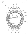
- a cable housing apparatus 10 of the present embodiment is used for housing a charging cable to be standard-equipped for an electric vehicle (EV) or a plug-in hybrid electric vehicle (PHEV). As shown in Figs. 1 to 3 , the cable housing apparatus 10 has a holder 32, a reel 22 detachably attached to the holder 32, and a support plate 12 attached to the reel 22.
- EV electric vehicle
- PHEV plug-in hybrid electric vehicle
- the holder 32 is made of resin.
- the holder 32 is installed on a wall surface or the like of a charging place (such as a home garage).
- the holder 32 includes a housing 33.
- the housing 33 is a plate shape member, in which one surface is fixed to the wall surface or the like of the charging place, and the reel 22 is attached to the other surface (refer to Fig. 2 in particular).
- Hooks 36, 38 are provided on the surface of the housing 33 on the side of the reel 22. When the support plate 12 is attached to the holder 32, the hooks 36, 38 are respectively engaged with a through hole 16 and grooves 18a, 18b of the support plate 12.
- the reel 22 includes a frame 24, and a holding member 28 attached to an inner peripheral edge of the frame 24.
- the frame 24 is formed in a cylindrical shape, and a cable main body 42 of a charging cable 40 is wound around an outer peripheral surface 24a thereof.
- walls 24b, 24c are formed on both ends of the outer peripheral surface 24a so as to project to the outer peripheral side.
- the walls 24b, 24c favorably prevent the charging cable 40 from dropping off of the outer peripheral surface 24a. That is, surfaces of the walls 24b, 24c to be abutted with the cable main body 42 (that is, inner surfaces) are formed as uneven surfaces as shown in Figs. 2 , 3 .
- an operation part 23 is formed in the wall 24b.
- the operation part 23 is a rod shape member, and a user can grip the operation part 23 to rotate the reel 22.
- a wall 25 is formed on the inner peripheral side of a holder side end (left end shown in Figs. 3 , 5 ) of the outer peripheral surface 24a.
- An inner peripheral part 26 of the wall 25 is bent to the non-holder side (right side of Fig. 5 ).
- the holding member (corresponding to a holding part in the claims) 28 is attached to a leading end of the inner peripheral part 26.
- an opening of the wall 25 is closed by the holding member 28, and a part of the holding member 28 is positioned inside the inner peripheral part 26.
- the holding member 28 detachably holds a CCID 44 and a plug 46 of the charging cable 40 on a surface thereof on the non-holder side (right surface shown in Figs. 3 , 5 ).
- the support plate 12 is a plate shape member, in which the holder 32 is abutted with one surface and the reel 22 is abutted with the other surface (refer to Fig. 2 in particular).
- a through hole 13 is formed in the center of the support plate 12, and a support part 14 is formed around the through hole 13.
- the support part 14 projects to the side of the reel 22.
- the support part 14 is inserted into a gap between the inner peripheral part 26 of the reel 22 and the holding member 28, and a leading end thereof is engaged with the holding member 28 (refer to Fig. 2 in particular).
- the through hole 16 is formed in an upper end of the support plate 12, and the pair of grooves 18a, 18b is formed in a lower end.
- the through hole 16 is used when the user grips the support plate 12. That is, by hanging fingers onto the through hole 16, the user can grip the upper end of the support plate 12.
- the through hole 16 and the grooves 18a, 18b are used for supporting the reel 22 and the support plate 12 when the reel 22 is attached to the holder 32. That is, as shown in Fig. 2 , when the reel 22 is attached to the holder 32, the hooks 36, 38 of the holder 32 are respectively engaged with the through hole 16 and the grooves 18a, 18b, so that the support plate 12 is supported.
- the charging cable 40 is an attached charging cable to be standard-equipped for an electric vehicle (EV) or a plug-in hybrid electric vehicle (PHEV).
- the charging cable 40 has the cable main body 42, a charging connector (not shown) provided in one end of the cable main body 42, the plug 46 provided in the other end of the cable main body 42, and the CCID 44 provided in the middle of the cable main body 42.
- the charging connector is connectable to a power feeding port of the electric vehicle or the plug-in hybrid electric vehicle.
- the charging cable 40 is connected to a battery mounted in the vehicle.
- the plug 46 is connectable to a connector part (such as an outlet) installed in the charging place.
- the CCID 44 is provided in the vicinity of the plug 46.
- the CCID 44 has a function of cancelling the connection between the external power source and the battery and stopping charging to the battery when charging is finished in a normal way or when a charging abnormality is generated.
- the reel 22 is assembled to the support plate 12
- the charging cable 40 is attached to the reel 22, and the support plate 12, the reel 22, and the charging cable 40 are taken along.
- the leading end of the support part 14 of the support plate 12 is engaged with the holding member 28.
- the reel 22 is rotatable with respect to the support plate 12.
- the CCID 44 and the plug 46 are attached to the holding member 28 of the reel 22.
- the CCID 44 and the plug 46 attached to the holding member 28 are housed on the inner peripheral side of the reel 22.
- the cable main body 42 extending toward the charging connector from the CCID 44 is pulled out to the outer peripheral surface 24a of the reel 22, and wound around the outer peripheral surface 24a of the reel 22.
- the user grabs the operation part 23 of the reel 22 by hand and rotates the reel 22 with respect to the support plate 12. Thereby, the user can wind the cable main body 42 around the reel 22 without directly touching the cable main body 42 by hand.
- the reel 22 and the support plate 12 are attached to the holder 32. Specifically, as shown in Fig. 2 , the hooks 36, 38 of the holder 32 are engaged with the through hole 16 and the grooves 18a, 18b of the support plate 12. Thereby, the support plate 12 is non-rotatably attached to the holder 32. Since the reel 22 is rotatable with respect to the support plate 12, the reel 22 can be rotated with respect to the holder 32.
- the charging connector provided in the other end of the charging cable 40 is connected to the power feeding port of the vehicle. That is, the necessary length of the charging cable 40 is pulled out from the reel 22, and the charging connector on a leading end thereof is connected to the power feeding port of the vehicle. It should be noted that since the reel 22 is rotatable with respect to the holder 32, the user rotates the reel 22 only by grabbing and pulling the charging connector, so that the charging cable 40 is pulled out from the reel 22. Therefore, at the time of pulling out the charging cable 40, there is no need for directly touching the cable main body 42 by hand.
- the plug 46 When the charging connector is connected to the power feeding port of the vehicle, next, the plug 46 is removed from the holding member 28, and the plug 46 is connected to the connector part (such as an outlet) provided in the charging place. Thereby, the external power source and the in-vehicle battery are connected, and charging of the in-vehicle battery is started.
- the plug 46 is removed from the connector part (outlet) and attached to the holding member 28.
- the charging connector is removed from the power feeding port of the vehicle, and the operation part 23 is operated to rotate the reel 22.
- the charging cable 40 (cable main body 42) is wound up on the reel 22. Since the reel 22 is operated by the operation part 23, there is no need for directly touching the cable main body 42 by hand at the time of taking up the charging cable 40.
- the reel 22 and the support plate 12 are detached from the holder 32. That is, the hooks 36, 38 are disengaged from the through hole 16 and the grooves 18a, 18b.
- the reel 22 on which the charging cable 40 is wound and the support plate 12 are housed in a trunk room of the vehicle.
- the holder 32 installed in the charging place is attachable to and detachable from the reel 22 (support plate 12 in detail), and the charging cable 40 is housed in the trunk room in a state where the charging cable is wound on the reel 22. Therefore, the charging cable 40 can be prevented from being disordered in the trunk room.
- the charging cable 40 can be pulled out from and wound up on the reel 22 by rotating the reel 22 with respect to the holder 32. Therefore, the charging cable 40 can be pulled out and wound up by a simple task. At the time of pulling out the charging cable 40 from the reel 22 or at the time of taking up the charging cable 40 on the reel 22, there is no need for directly touching the charging cable 40 by hand. Therefore, even when the charging cable 40 is dirty, hands do not get dirty by this.
- the CCID 44 is held by the holding member 28 of the reel 22 at the time of charging, the CCID 44 is not suspended from the cable main body 42. That is, when the plug 46 is inserted into the connector part (outlet) of the charging place in a state where the CCID 44 is not held by the reel 22, the CCID 44 is suspended from the cable main body 42. As a result, a large tensile force is applied to the cable main body 42, so that damage to the charging cable 40 is caused. In the cable housing apparatus 10 of the present embodiment, since the CCID 44 is held by the holding member 28, such a problem is not generated.
- the plug 46 of the charging cable 40 is inserted into the connector part (outlet) installed in the charging place.
- a cable housing apparatus 50 of a second embodiment is different at a point where the plug 46 of the charging cable 40 is connected to a holder, and the holder and the connector part (outlet) installed in the charging place are connected by another electric cable. It should be noted that at the other points, the cable housing apparatus has the substantially same configuration as the cable housing apparatus 10 of the first embodiment. Thus, parts different from the first embodiment will be mainly described.
- the cable housing apparatus 50 has a holder 70, and a reel 52 attachable to and detachable from the holder 70.
- the holder 70 has a housing 72, and a rotation plate (corresponding to a first connection part in the claims) 74 rotatably provided on a surface of the housing 72 on the side of the reel.
- the rotation plate 74 is fixed to a rotation shaft 77, and the rotation shaft 77 is supported to be rotatable with respect to the housing 72.
- An insertion part 76 into which the plug 46 of the charging cable 40 is inserted is formed in the center of the rotation plate 74.
- a fitting concave part (corresponding to a first fitting part in the claims) 75 is formed on the outer side of the insertion part 76 of the rotation plate 74.
- a hook (not shown) is provided on the surface of the housing 72 on the side of the reel.
- an engagement part (not shown) (such as a concave part formed on a surface on the side of the holder) of the reel 52 to be described later. Thereby, the reel 52 does not drop off of the holder 70.
- the holder 70 has an electric cable (corresponding to a second connection part in the claims) 78 for connecting the external power source and the holder 70.
- a plug 80 is provided in a leading end of the electric cable 78.
- the plug 80 is inserted into the connector part (outlet) installed in the charging place. It should be noted that in a case where the electric cable 78 of the holder 70 is directly connected to the power source, there is no need for providing the plug 80 in the leading end of the electric cable 78.
- the insertion part 76 of the rotation plate 74 and the electric cable 78 are electrically connected via a slip ring 71.
- the insertion part 76 and the slip ring 71 are connected by a wire 73, and the electric cable 78 and the slip ring 71 are connected by a wire 79. Thereby, the insertion part 76 and the electric cable 78 are electrically connected.
- the reel 52 has a rotation drum 54, and a casing 56 for rotatably supporting the rotation drum 54.
- the cable main body 42 of the charging cable 40 is wound around an outer peripheral surface of the rotation drum 54.
- a charging connector 48 of the charging cable 40 is locked on a hook 55 arranged on the outer peripheral side of the rotation drum 54.
- the CCID 44 and the plug 46 are held on the inner side of the rotation drum 54.
- a through hole 64 passing through from a surface on the side of the reel to a surface on the side of the holder is formed in the casing 56.
- the through hole 64 has the diameter larger than the plug 46 of the charging cable 40.
- the insertion part 76 of the rotation plate 74, the through hole 64 of the casing 56, and the rotation axis of the rotation drum 54 are placed at the same position.
- a fitting convex part (corresponding to a second fitting part in the claims) 62 to be fitted to the fitting concave part 75 of the rotation plate 74 is formed around the through hole 64. It should be noted that since the through hole 64 is formed on the rotation axis line of the rotation drum 54, the CCID 44 and the plug 46 are held at positions displaced from the rotation axis line of the rotation drum 54.
- the reel 52 is attached to the holder 70. That is, the fitting convex part 62 formed on the surface of the reel 52 on the side of the holder is fitted to the fitting concave part 75 formed on the surface of the holder 70 on the side of the reel. Thereby, the reel 52 is attached to the holder 70.
- the rotation plate 74 in which the fitting concave part 75 is formed is rotatable with respect to the housing 72.
- the rotation plate 74 and the reel 52 can be integrated with each other and rotated with respect to the housing 72.
- the plug 46 of the charging cable 40 is inserted into the insertion part 76 of the rotation plate 74 through the through hole 64 of the casing 56.
- the charging cable 40 and the external power source are electrically connected only by inserting the plug 46 of the charging cable 40 into the insertion part 76 of the rotation plate 74.
- the user pulls out the necessary length of the cable main body 42 from the reel 52 by grabbing and pulling the charging connector 48.
- the insertion part 76 is positioned on the rotation axis line of the reel 52, and the reel 52 and the rotation plate 74 are integrated with each other and rotated.
- Rotation torque for rotating the rotation plate 74 is transmitted from the reel 52 to the rotation plate 74 via the fitting convex part 62 and the fitting concave part 75.
- the torque is not applied to the charging cable 40. Thereby, the damage to the charging cable 40 is prevented.
- the charging connector is connected to the power feeding port of the vehicle and charging of the in-vehicle battery is started. Meanwhile, when charging to the in-vehicle battery is finished, firstly, the charging connector is removed from the power feeding port of the vehicle, and then the reel 52 is rotated and the charging cable 40 (cable main body 42) is wound up on the reel 52. Next, the plug 46 of the charging cable 40 is detached from the insertion part 76 and the reel 52 is separated from the holder 70.
- the charging cable 40 is housed in the trunk room of the vehicle in a state where the charging cable is wound around the reel 52.
- the holder 70 is connected to the external power source by the electric cable 78, and only by inserting the plug 46 of the charging cable 40 into the insertion part 76 of the holder 70, the external power source and the charging cable 40 can be electrically connected
- the charging cable 40 can be pulled out from the reel 52 and the charging cable 40 can be wound up on the reel 52.
- a connection task of the charging cable 40 can be extremely simply performed. Since the slip ring 71 is provided on the side of the holder 70, weight of the reel 52 to be taken along can be reduced.
- the reel 52 is manually rotated and the charging cable 40 is wound around the reel 52.
- the rotation plate 74 and the reel 52 may be biased in the take-up direction by attaching a flat spiral spring 84 to the other end of the rotation shaft 77. That is, when the charging cable 40 is pulled out from the reel 52, the reel 52 is rotated in the cable pull-out direction against a bias force of the flat spiral spring 84.
- the reel 52 is rotated in the cable take-up direction by the bias force of the flat spiral spring 84.
- the charging cable 40 can be automatically wound up on the reel 52.
- the reel 52 may be enabled to stop at an arbitrary position by a ratchet mechanism for example.
- a switch for cancelling the ratchet mechanism may be separately provided, and by operating the switch, the reel 52 may be rotated in the cable take-up direction.
- the charging cable 40 may be pulled out from the reel 52 and the charging cable 40 may be wound up on the reel 52.
- an external power source may be used or an internal power source (built-in battery) may be used as a power source of the motor 88.
- the CCID 44 is arranged at the position displaced from the rotation axis line of the reel 52.
- the CCID 44 may be arranged on the rotation axis line of the reel 52.
- the diameter of the reel 52 can be reduced. It should be noted that when the CCID 44 is arranged on the rotation axis line of the reel 52, the plug 46 of the charging cable 40 is not easily directly connected to the insertion part 76 of the holder 70. Therefore, in the cable housing apparatus shown in Fig.
- the plug 46 of the charging cable 40 is connected to an adaptor 96, and a plug (corresponding to a reel side plug in the claims) 96a electrically connected to the adaptor 96 is connected to the insertion part 76 of the holder 70.
- the charging cable 40 can be connected to an electric cable (corresponding to a fourth connection part in the claims) 87 of the holder 70.
- the insertion part 76 projecting toward the side of the reel is formed in a rotation plate 84 (corresponding to a third connection part in the claims) of the holder 70, and the adaptor 96 is movable in the arrow direction in the figure.
- the cable housing apparatus can be switched between (1) a state where the reel 52 is attached to the holder 70 and the insertion part 76 and the plug 96a are connected (state where the adaptor 96 is moved to the side of the holder), and (2) a state where the reel 52 is attached to the holder 70 and the insertion part 76 and the plug 96a are not connected (state where the adaptor 96 is moved to the non-holder side).
- the charging cable 40 may be wound up in the radial direction of a reel 90. With such a configuration, the axial size of the reel 90 can be reduced. It should be noted that in the example shown in Fig. 13 , the CCID 44 of the charging cable 40 is held by a holding member 94 provided on an end surface of the reel 90.
- the above embodiments show the cable housing apparatuses for housing the charging cable serving as standard equipment.
- the individual techniques described in the present specification can be applied to a cable housing apparatus in which a charging cable and a housing apparatus thereof are exclusively designed.
Abstract
A cable housing apparatus disclosed in the present specification can house a charging cable serving as standard equipment in a trunk room in an organized state without a troublesome task. This cable housing apparatus houses a charging cable having a charging connector provided in one end, a plug provided in the other end, and a CCID provided between the charging connector and the plug. The cable housing apparatus has a holder, and a reel detachably attached to the holder. The reel has an outer peripheral surface on which the charging cable is capable of being wound, and a holding part capable of holding the CCID.
Description
- The technique disclosed in the present specification relates to a cable housing apparatus for housing a charging cable. In detail, the technique relates to a cable housing apparatus for housing a charging cable to be used for charging an electric vehicle (EV) or a plug-in hybrid electric vehicle (PHEV).
- As a conventional technique of this type of housing apparatus for housing a charging cable, there is a known cable housing apparatus of Japanese Patent Application Publication No.
2010-115037 - Upon purchase of an electric vehicle or a plug-in hybrid electric vehicle, a charging cable serving as standard equipment is attached in general. In this charging cable serving as the standard equipment, a charging connector is provided in one end, a plug is provided in the other end, and a CCID (Charging Circuit Interrupt Device) is provided between the charging connector and the plug. This charging cable is for example housed in a trunk room and used when charging is required away from home, or housed in a home garage or the like and used when charging is required at home.
- When the above charging cable serving as the standard equipment is housed in the trunk room or housed in the home garage or the like, it is recommended to house the charging cable within a bag such as a carrier bag. That is, it is recommended to roll up the charging cable, place the rolled charging cable into the bag, and house the charging cable within the bag. However, the electric vehicle or the like is highly frequently charged, unlike oil supply to a gasoline-driven vehicle. In a case where the electric vehicle or the like is used for commutation, charging is generally performed every day. Therefore, even though it is recommended, the charging cable is often not placed in the bag, and some may just disorderly shove the charging cable in a housing place without rolling up the charging cable. As a result, when other items are housed in the trunk room or in the garage, problems such as the charging cable being an obstruction are generated. It should be noted that in the cable housing apparatus of Japanese Patent Application Publication No.
2010-115037 - The present specification discloses a cable housing apparatus capable of housing a charging cable serving as standard equipment in a housing place in an organized state.
- A cable housing apparatus disclosed in the present specification houses a charging cable having a charging connector provided in one end, a plug provided in the other end, and a CCID provided between the charging connector and the plug. This cable housing apparatus includes a reel having an outer peripheral surface on which the charging cable is capable of being wound.
- This cable housing apparatus includes the reel having the outer peripheral surface on which the charging cable is capable of being wound. Therefore, the charging cable can be housed in a housing place such as a trunk room in a state where the charging cable is wound on the outer peripheral surface of the reel and organized.
-
-
Fig. 1 is a front view of a cable housing apparatus of the present embodiment. -
Fig. 2 is a vertically sectional view of the cable housing apparatus ofFig. 1 . -
Fig. 3 is a vertically sectional view showing exploded parts of the cable housing apparatus. -
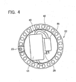
Fig. 4 is a front view of a reel. -
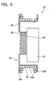
Fig. 5 is a vertically sectional view of the reel shown inFig. 4 . -
Fig. 6 is a front view of a support plate. -
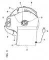
Fig. 7 is a perspective view of a cable housing apparatus of a second embodiment (part I). -
Fig. 8 is a perspective view of the cable housing apparatus of the second embodiment (part II). -
Fig. 9 is a schematic view showing an internal structure of the cable housing apparatus of the second embodiment. -
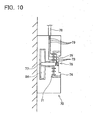
Fig. 10 is a view showing a modified example of the second embodiment. -
Fig. 11 is a view showing another modified example of the second embodiment. -
Fig. 12 is a view showing still another modified example of the second embodiment. -
Fig. 13 is a front view of a cable housing apparatus according to yet another modified example of the second embodiment. - In a cable housing apparatus disclosed in the present specification, a reel may have a holding part capable of holding a CCID. With such a configuration, the CCID of a charging cable can be held on a holding part of the reel. Thus, the CCID is not suspended hanging from the cable at the time of charging, and a large tensile force can be prevented from being applied to the cable and the plug.
- The above cable housing apparatus may further include a holder for rotatably supporting the reel. With such a configuration, by rotating the reel with respect to the holder, the charging cable can be pulled out and wound up. Since there is no need for directly touching the charging cable by a hand, hands do not get dirty by the dirty charging cable dirtied due to dust, rainwater, ground, and the like.
- In the above cable housing apparatus, the reel may be detachably attached to the holder. With such a configuration, in a case where the charging cable is used both away from home and at home, the charging cable can be easily handled. That is, with such a configuration, the reel on which the charging cable is wound is attachable to and detachable from the holder. Therefore, the holder can be installed in a charging place (such as a home garage) and only the charging cable and the reel can be taken along. Thus, at the time of charging a battery at home or the like, the reel is attached to the holder installed in the charging place, and the charging cable is pulled out from the reel, so that charging can be performed. Meanwhile, when charging is finished, the charging cable is wound on the reel attached to the holder, then the reel is detached from the holder, and the charging cable can be housed in a trunk room all together with the reel. Since the charging cable can be housed in the trunk room in a state where the charging cable is wound on the reel, the charging cable can be prevented from being disordered in the trunk room. Since the charging cable can be pulled out from and wound up on the reel while the reel is attached to the holder, pull-out and take-up tasks of the charging cable can be easily performed.
- In a case where the reel is rotatably attached to the holder, the holder may have a housing, a first connection part, a second connection part, and a slip ring. The first connection part may be provided to be rotatable with respect to the housing, and the plug of the charging cable may be detachably connected to the first connection part. The second connection part may be provided immovably with respect to the housing and connected to an external power source. The slip ring may be arranged between the first connection part and the second connection part, and the slip ring may electrically connect the first connection part and the second connection part.
- In the cable housing apparatus of the above mode, the holder has the first connection part rotatable with respect to the housing. Therefore, while the plug of the charging cable is connected to the first connection part, the reel can be rotated and the charging cable can be pulled out and wound up. Since the slip ring is provided on the side of the holder, weight on the side of the reel to be taken along can be reduced.
- In the cable housing apparatus of the above mode, further, the first connection part may have a rotation member rotatably supported by the housing, a first fitting part formed in the rotation member, and an insertion part formed in the rotation member, the insertion part into which the plug of the charging cable is inserted. In this case, the reel may have a second fitting part to be fitted to the first fitting part, and by fitting the first fitting part of the first connection part to the second fitting part of the reel, the reel and the first connection part may be integrated with each other and rotated with respect to the housing. With such a configuration, the reel and the rotation member are integrated with each other and rotated, and no position gap is generated between the reel and the rotation member. Torque can be transmitted from the reel to the rotation member via the first fitting part and the second fitting part. Therefore, no torque is generated between the plug of the charging cable and the first connection part, so that damage to the charging cable can be prevented.
- In another mode of the above cable housing apparatus, the reel may have an adaptor to be rotatably attached to the holder, the adaptor to which the plug of the charging cable is detachably connected, and a reel side plug connected to the adaptor. The holder may have a housing, a third connection part, a fourth connection part, and a slip ring. The third connection part may be provided to be rotatable with respect to the housing, and the reel side plug may be detachably connected to the third connection part. The fourth connection part may be provided immovably with respect to the housing and connected to an external power source. The slip ring may be arranged between the third connection part and the fourth connection part, and the slip ring may electrically connect the third connection part and the fourth connection part. With such a configuration, since the charging cable is connected to the holder via the adaptor, the holding part for holding the CCID can be provided on the rotation axis line of the reel. Therefore, the diameter of the reel can be reduced.
- A
cable housing apparatus 10 of the present embodiment is used for housing a charging cable to be standard-equipped for an electric vehicle (EV) or a plug-in hybrid electric vehicle (PHEV). As shown inFigs. 1 to 3 , thecable housing apparatus 10 has aholder 32, areel 22 detachably attached to theholder 32, and asupport plate 12 attached to thereel 22. - The
holder 32 is made of resin. Theholder 32 is installed on a wall surface or the like of a charging place (such as a home garage). As shown inFig. 3 , theholder 32 includes ahousing 33. Thehousing 33 is a plate shape member, in which one surface is fixed to the wall surface or the like of the charging place, and thereel 22 is attached to the other surface (refer toFig. 2 in particular).Hooks housing 33 on the side of thereel 22. When thesupport plate 12 is attached to theholder 32, thehooks hole 16 andgrooves support plate 12. - As shown in
Figs. 3 to 5 , thereel 22 includes aframe 24, and a holdingmember 28 attached to an inner peripheral edge of theframe 24. Theframe 24 is formed in a cylindrical shape, and a cablemain body 42 of a chargingcable 40 is wound around an outerperipheral surface 24a thereof. As shown inFigs. 3 ,5 ,walls peripheral surface 24a so as to project to the outer peripheral side. Thewalls cable 40 from dropping off of the outerperipheral surface 24a. That is, surfaces of thewalls Figs. 2 ,3 . Thereby, the cablemain body 42 is prevented from going over thewalls frame 24, that is, the cablemain body 42 is prevented from dropping off of the outerperipheral surface 24a. As shown inFigs. 1 ,4 , anoperation part 23 is formed in thewall 24b. Theoperation part 23 is a rod shape member, and a user can grip theoperation part 23 to rotate thereel 22. Meanwhile, awall 25 is formed on the inner peripheral side of a holder side end (left end shown inFigs. 3 ,5 ) of the outerperipheral surface 24a. An innerperipheral part 26 of thewall 25 is bent to the non-holder side (right side ofFig. 5 ). The holding member (corresponding to a holding part in the claims) 28 is attached to a leading end of the innerperipheral part 26. When the holdingmember 28 is attached to the innerperipheral part 26, an opening of thewall 25 is closed by the holdingmember 28, and a part of the holdingmember 28 is positioned inside the innerperipheral part 26. The holdingmember 28 detachably holds aCCID 44 and aplug 46 of the chargingcable 40 on a surface thereof on the non-holder side (right surface shown inFigs. 3 ,5 ). - As shown in
Figs. 1 ,2 ,3 ,6 , thesupport plate 12 is a plate shape member, in which theholder 32 is abutted with one surface and thereel 22 is abutted with the other surface (refer toFig. 2 in particular). A throughhole 13 is formed in the center of thesupport plate 12, and asupport part 14 is formed around the throughhole 13. Thesupport part 14 projects to the side of thereel 22. Thesupport part 14 is inserted into a gap between the innerperipheral part 26 of thereel 22 and the holdingmember 28, and a leading end thereof is engaged with the holding member 28 (refer toFig. 2 in particular). When the leading end of thesupport part 14 is engaged with the holdingmember 28, a part of the holdingmember 28 is positioned inside thesupport part 14, and thereel 22 becomes rotatable with respect to thesupport part 14. The throughhole 16 is formed in an upper end of thesupport plate 12, and the pair ofgrooves hole 16 is used when the user grips thesupport plate 12. That is, by hanging fingers onto the throughhole 16, the user can grip the upper end of thesupport plate 12. The throughhole 16 and thegrooves reel 22 and thesupport plate 12 when thereel 22 is attached to theholder 32. That is, as shown inFig. 2 , when thereel 22 is attached to theholder 32, thehooks holder 32 are respectively engaged with the throughhole 16 and thegrooves support plate 12 is supported. - Next, the charging
cable 40 to be wound around thereel 22 will be described. The chargingcable 40 is an attached charging cable to be standard-equipped for an electric vehicle (EV) or a plug-in hybrid electric vehicle (PHEV). The chargingcable 40 has the cablemain body 42, a charging connector (not shown) provided in one end of the cablemain body 42, theplug 46 provided in the other end of the cablemain body 42, and theCCID 44 provided in the middle of the cablemain body 42. The charging connector is connectable to a power feeding port of the electric vehicle or the plug-in hybrid electric vehicle. When the charging connector is connected to the power feeding port of the vehicle, the chargingcable 40 is connected to a battery mounted in the vehicle. Theplug 46 is connectable to a connector part (such as an outlet) installed in the charging place. When theplug 46 is connected to the connector part of the charging place, an external power source and the chargingcable 40 are connected. TheCCID 44 is provided in the vicinity of theplug 46. TheCCID 44 has a function of cancelling the connection between the external power source and the battery and stopping charging to the battery when charging is finished in a normal way or when a charging abnormality is generated. - Next, actions of the above
cable housing apparatus 10 will be described. In thecable housing apparatus 10 of the present embodiment, thereel 22 is assembled to thesupport plate 12, the chargingcable 40 is attached to thereel 22, and thesupport plate 12, thereel 22, and the chargingcable 40 are taken along. - In order to assemble the
reel 22 to thesupport plate 12, the leading end of thesupport part 14 of thesupport plate 12 is engaged with the holdingmember 28. When thereel 22 is assembled to thesupport plate 12, thereel 22 is rotatable with respect to thesupport plate 12. In order to attach the chargingcable 40 to thereel 22, firstly, as shown inFigs. 1 ,2 ,4 ,5 , theCCID 44 and theplug 46 are attached to the holdingmember 28 of thereel 22. TheCCID 44 and theplug 46 attached to the holdingmember 28 are housed on the inner peripheral side of thereel 22. The cablemain body 42 extending toward the charging connector from theCCID 44 is pulled out to the outerperipheral surface 24a of thereel 22, and wound around the outerperipheral surface 24a of thereel 22. At the time of winding the cablemain body 42 around the outerperipheral surface 24a of thereel 22, the user grabs theoperation part 23 of thereel 22 by hand and rotates thereel 22 with respect to thesupport plate 12. Thereby, the user can wind the cablemain body 42 around thereel 22 without directly touching the cablemain body 42 by hand. - When the in-vehicle battery is charged by using the charging
cable 40, firstly, thereel 22 and thesupport plate 12 are attached to theholder 32. Specifically, as shown inFig. 2 , thehooks holder 32 are engaged with the throughhole 16 and thegrooves support plate 12. Thereby, thesupport plate 12 is non-rotatably attached to theholder 32. Since thereel 22 is rotatable with respect to thesupport plate 12, thereel 22 can be rotated with respect to theholder 32. - When the
reel 22 and thesupport plate 12 are attached to theholder 32, firstly, the charging connector provided in the other end of the chargingcable 40 is connected to the power feeding port of the vehicle. That is, the necessary length of the chargingcable 40 is pulled out from thereel 22, and the charging connector on a leading end thereof is connected to the power feeding port of the vehicle. It should be noted that since thereel 22 is rotatable with respect to theholder 32, the user rotates thereel 22 only by grabbing and pulling the charging connector, so that the chargingcable 40 is pulled out from thereel 22. Therefore, at the time of pulling out the chargingcable 40, there is no need for directly touching the cablemain body 42 by hand. When the charging connector is connected to the power feeding port of the vehicle, next, theplug 46 is removed from the holdingmember 28, and theplug 46 is connected to the connector part (such as an outlet) provided in the charging place. Thereby, the external power source and the in-vehicle battery are connected, and charging of the in-vehicle battery is started. - When charging to the in-vehicle battery is finished, firstly, the
plug 46 is removed from the connector part (outlet) and attached to the holdingmember 28. Next, the charging connector is removed from the power feeding port of the vehicle, and theoperation part 23 is operated to rotate thereel 22. Thereby, the charging cable 40 (cable main body 42) is wound up on thereel 22. Since thereel 22 is operated by theoperation part 23, there is no need for directly touching the cablemain body 42 by hand at the time of taking up the chargingcable 40. After the chargingcable 40 is wound up on thereel 22, thereel 22 and thesupport plate 12 are detached from theholder 32. That is, thehooks hole 16 and thegrooves reel 22 on which the chargingcable 40 is wound and thesupport plate 12 are housed in a trunk room of the vehicle. - As is clear from the above description, in the
cable housing apparatus 10 of the present embodiment, theholder 32 installed in the charging place is attachable to and detachable from the reel 22 (support plate 12 in detail), and the chargingcable 40 is housed in the trunk room in a state where the charging cable is wound on thereel 22. Therefore, the chargingcable 40 can be prevented from being disordered in the trunk room. - The charging
cable 40 can be pulled out from and wound up on thereel 22 by rotating thereel 22 with respect to theholder 32. Therefore, the chargingcable 40 can be pulled out and wound up by a simple task. At the time of pulling out the chargingcable 40 from thereel 22 or at the time of taking up the chargingcable 40 on thereel 22, there is no need for directly touching the chargingcable 40 by hand. Therefore, even when the chargingcable 40 is dirty, hands do not get dirty by this. - Further, since the
CCID 44 is held by the holdingmember 28 of thereel 22 at the time of charging, theCCID 44 is not suspended from the cablemain body 42. That is, when theplug 46 is inserted into the connector part (outlet) of the charging place in a state where theCCID 44 is not held by thereel 22, theCCID 44 is suspended from the cablemain body 42. As a result, a large tensile force is applied to the cablemain body 42, so that damage to the chargingcable 40 is caused. In thecable housing apparatus 10 of the present embodiment, since theCCID 44 is held by the holdingmember 28, such a problem is not generated. - In the
cable housing apparatus 10 of the above first embodiment, theplug 46 of the chargingcable 40 is inserted into the connector part (outlet) installed in the charging place. However, acable housing apparatus 50 of a second embodiment is different at a point where theplug 46 of the chargingcable 40 is connected to a holder, and the holder and the connector part (outlet) installed in the charging place are connected by another electric cable. It should be noted that at the other points, the cable housing apparatus has the substantially same configuration as thecable housing apparatus 10 of the first embodiment. Thus, parts different from the first embodiment will be mainly described. - As shown in
Figs. 7 to 9 , thecable housing apparatus 50 has aholder 70, and areel 52 attachable to and detachable from theholder 70. As shown inFig. 7 , theholder 70 has ahousing 72, and a rotation plate (corresponding to a first connection part in the claims) 74 rotatably provided on a surface of thehousing 72 on the side of the reel. As shown inFig. 9 , therotation plate 74 is fixed to arotation shaft 77, and therotation shaft 77 is supported to be rotatable with respect to thehousing 72. Aninsertion part 76 into which theplug 46 of the chargingcable 40 is inserted is formed in the center of therotation plate 74. A fitting concave part (corresponding to a first fitting part in the claims) 75 is formed on the outer side of theinsertion part 76 of therotation plate 74. It should be noted that a hook (not shown) is provided on the surface of thehousing 72 on the side of the reel. When thereel 52 is attached to theholder 70, the hook of thehousing 72 is engaged with an engagement part (not shown) (such as a concave part formed on a surface on the side of the holder) of thereel 52 to be described later. Thereby, thereel 52 does not drop off of theholder 70. - As shown in
Fig. 8 , theholder 70 has an electric cable (corresponding to a second connection part in the claims) 78 for connecting the external power source and theholder 70. Aplug 80 is provided in a leading end of theelectric cable 78. Theplug 80 is inserted into the connector part (outlet) installed in the charging place. It should be noted that in a case where theelectric cable 78 of theholder 70 is directly connected to the power source, there is no need for providing theplug 80 in the leading end of theelectric cable 78. As shown inFig. 9 , theinsertion part 76 of therotation plate 74 and theelectric cable 78 are electrically connected via aslip ring 71. That is, theinsertion part 76 and theslip ring 71 are connected by awire 73, and theelectric cable 78 and theslip ring 71 are connected by awire 79. Thereby, theinsertion part 76 and theelectric cable 78 are electrically connected. - As shown in
Fig. 7 , thereel 52 has arotation drum 54, and acasing 56 for rotatably supporting therotation drum 54. The cablemain body 42 of the chargingcable 40 is wound around an outer peripheral surface of therotation drum 54. A chargingconnector 48 of the chargingcable 40 is locked on ahook 55 arranged on the outer peripheral side of therotation drum 54. TheCCID 44 and theplug 46 are held on the inner side of therotation drum 54. As shown inFig. 8 , a throughhole 64 passing through from a surface on the side of the reel to a surface on the side of the holder is formed in thecasing 56. The throughhole 64 has the diameter larger than theplug 46 of the chargingcable 40. When thecable housing apparatus 50 is seen along the rotation axis of therotation drum 54, theinsertion part 76 of therotation plate 74, the throughhole 64 of thecasing 56, and the rotation axis of therotation drum 54 are placed at the same position. A fitting convex part (corresponding to a second fitting part in the claims) 62 to be fitted to the fittingconcave part 75 of therotation plate 74 is formed around the throughhole 64. It should be noted that since the throughhole 64 is formed on the rotation axis line of therotation drum 54, theCCID 44 and theplug 46 are held at positions displaced from the rotation axis line of therotation drum 54. - In a case where charging is performed by the above
cable housing apparatus 50, thereel 52 is attached to theholder 70. That is, the fittingconvex part 62 formed on the surface of thereel 52 on the side of the holder is fitted to the fittingconcave part 75 formed on the surface of theholder 70 on the side of the reel. Thereby, thereel 52 is attached to theholder 70. Therotation plate 74 in which the fittingconcave part 75 is formed is rotatable with respect to thehousing 72. Thus, therotation plate 74 and thereel 52 can be integrated with each other and rotated with respect to thehousing 72. Next, theplug 46 of the chargingcable 40 is inserted into theinsertion part 76 of therotation plate 74 through the throughhole 64 of thecasing 56. When theplug 80 of theelectric cable 78 is connected to the connector part (outlet) of the charging place in advance, the chargingcable 40 and the external power source are electrically connected only by inserting theplug 46 of the chargingcable 40 into theinsertion part 76 of therotation plate 74. - After the
reel 52 is attached to theholder 70, the user pulls out the necessary length of the cablemain body 42 from thereel 52 by grabbing and pulling the chargingconnector 48. At this time, theinsertion part 76 is positioned on the rotation axis line of thereel 52, and thereel 52 and therotation plate 74 are integrated with each other and rotated. Thus, a problem that the chargingcable 40 is twisted or the like is not generated. Rotation torque for rotating therotation plate 74 is transmitted from thereel 52 to therotation plate 74 via the fittingconvex part 62 and the fittingconcave part 75. Thus, the torque is not applied to the chargingcable 40. Thereby, the damage to the chargingcable 40 is prevented. Next, the charging connector is connected to the power feeding port of the vehicle and charging of the in-vehicle battery is started. Meanwhile, when charging to the in-vehicle battery is finished, firstly, the charging connector is removed from the power feeding port of the vehicle, and then thereel 52 is rotated and the charging cable 40 (cable main body 42) is wound up on thereel 52. Next, theplug 46 of the chargingcable 40 is detached from theinsertion part 76 and thereel 52 is separated from theholder 70. The chargingcable 40 is housed in the trunk room of the vehicle in a state where the charging cable is wound around thereel 52. - As is clear from the above description, in the
cable housing apparatus 50 of the present embodiment, theholder 70 is connected to the external power source by theelectric cable 78, and only by inserting theplug 46 of the chargingcable 40 into theinsertion part 76 of theholder 70, the external power source and the chargingcable 40 can be electrically connected In a state where theplug 46 of the chargingcable 40 is inserted into theinsertion part 76 of theholder 70, the chargingcable 40 can be pulled out from thereel 52 and the chargingcable 40 can be wound up on thereel 52. Thereby, a connection task of the chargingcable 40 can be extremely simply performed. Since theslip ring 71 is provided on the side of theholder 70, weight of thereel 52 to be taken along can be reduced. - It should be noted that in the
cable housing apparatus 50 of the above second embodiment, at the time of taking up the chargingcable 40 on thereel 52, thereel 52 is manually rotated and the chargingcable 40 is wound around thereel 52. However, as shown inFig. 10 , therotation plate 74 and thereel 52 may be biased in the take-up direction by attaching aflat spiral spring 84 to the other end of therotation shaft 77. That is, when the chargingcable 40 is pulled out from thereel 52, thereel 52 is rotated in the cable pull-out direction against a bias force of theflat spiral spring 84. When the chargingcable 40 is wound up on thereel 52, thereel 52 is rotated in the cable take-up direction by the bias force of theflat spiral spring 84. Thereby, the chargingcable 40 can be automatically wound up on thereel 52. It should be noted that when thereel 52 is rotated in the pull-out direction, thereel 52 may be enabled to stop at an arbitrary position by a ratchet mechanism for example. It should be noted that in a case where the ratchet mechanism is provided, a switch for cancelling the ratchet mechanism may be separately provided, and by operating the switch, thereel 52 may be rotated in the cable take-up direction. Further, as shown inFig. 11 , by driving and rotating therotation shaft 77 by amotor 88, the chargingcable 40 may be pulled out from thereel 52 and the chargingcable 40 may be wound up on thereel 52. It should be noted that an external power source may be used or an internal power source (built-in battery) may be used as a power source of themotor 88. - In the
cable housing apparatus 50 of the above second embodiment, as shown inFig. 7 , theCCID 44 is arranged at the position displaced from the rotation axis line of thereel 52. However, as shown inFig 12 , theCCID 44 may be arranged on the rotation axis line of thereel 52. By arranging theCCID 44 on the rotation axis line of thereel 52, the diameter of thereel 52 can be reduced. It should be noted that when theCCID 44 is arranged on the rotation axis line of thereel 52, theplug 46 of the chargingcable 40 is not easily directly connected to theinsertion part 76 of theholder 70. Therefore, in the cable housing apparatus shown inFig. 12 , theplug 46 of the chargingcable 40 is connected to anadaptor 96, and a plug (corresponding to a reel side plug in the claims) 96a electrically connected to theadaptor 96 is connected to theinsertion part 76 of theholder 70. Thereby, the chargingcable 40 can be connected to an electric cable (corresponding to a fourth connection part in the claims) 87 of theholder 70. It should be noted that in the cable housing apparatus shown inFig. 12 , theinsertion part 76 projecting toward the side of the reel is formed in a rotation plate 84 (corresponding to a third connection part in the claims) of theholder 70, and theadaptor 96 is movable in the arrow direction in the figure. Thereby, the cable housing apparatus can be switched between (1) a state where thereel 52 is attached to theholder 70 and theinsertion part 76 and theplug 96a are connected (state where theadaptor 96 is moved to the side of the holder), and (2) a state where thereel 52 is attached to theholder 70 and theinsertion part 76 and theplug 96a are not connected (state where theadaptor 96 is moved to the non-holder side). - Further, as in the cable housing apparatus shown in
Fig. 13 , the chargingcable 40 may be wound up in the radial direction of areel 90. With such a configuration, the axial size of thereel 90 can be reduced. It should be noted that in the example shown inFig. 13 , theCCID 44 of the chargingcable 40 is held by a holdingmember 94 provided on an end surface of thereel 90. - It should be noted that the above embodiments show the cable housing apparatuses for housing the charging cable serving as standard equipment. However, the individual techniques described in the present specification (such as the technique that the holder has the slip ring) can be applied to a cable housing apparatus in which a charging cable and a housing apparatus thereof are exclusively designed.
- Specific examples of the present invention has been described in detail, however, these are mere exemplary indications and thus do not limit the scope of the claims. The art described in the claims include modifications and variations of the specific examples presented above. Technical features described in the description and the drawings may technically be useful alone or in various combinations, and are not limited to the combinations as originally claimed. Further, the art described in the description and the drawings may concurrently achieve a plurality of aims, and technical significance thereof resides in achieving any one of such aims.
Claims (7)
- A cable housing apparatus for housing a charging cable having a charging connector provided in one end, a plug provided in the other end, and a CCID provided between the charging connector and the plug, the cable housing apparatus comprising:a reel having an outer peripheral surface on which the charging cable is capable of being wound.
- The cable housing apparatus according to claim 1, wherein the reel comprises a holding part capable of holding the CCID.
- The cable housing apparatus according to claim 1 or 2, further comprising:a holder for rotatably supporting the reel.
- The cable housing apparatus according to claim 3, wherein the reel is detachably attached to the holder.
- The cable housing apparatus according to claim 3 or 4, wherein
the holder comprises:a housing;a first connection part provided to be rotatable with respect to the housing, the first connection part to which the plug of the charging cable is detachably connected;a second connection part provided immovably with respect to the housing and connected to an external power source; anda slip ring arranged between the first connection part and the second connection part, the slip ring for electrically connecting the first connection part and the second connection part. - The cable housing apparatus according to claim 5, wherein
the first connection part comprises a rotation member rotatably supported by the housing, a first fitting part formed in the rotation member, and an insertion part formed in the rotation member, the insertion part into which the plug of the charging cable is inserted,
the reel includes a second fitting part to be fitted to the first fitting part, and
by fitting the first fitting part of the first connection part to the second fitting part of the reel, the reel and the first connection part are integrated with each other and rotated with respect to the housing. - The cable housing apparatus according to claim 4, wherein
the reel comprises an adaptor to which the plug of the charging cable is detachably connected, and a reel side plug connected to the adaptor, and
the holder comprises:a housing;a third connection part provided to be rotatable with respect to the housing, the third connection part to which the reel side plug is detachably connected;a fourth connection part provided immovably with respect to the housing and connected to an external power source; anda slip ring arranged between the third connection part and the fourth connection part, the slip ring for electrically connecting the third connection part and the fourth connection part.
Applications Claiming Priority (3)
| Application Number | Priority Date | Filing Date | Title |
|---|---|---|---|
| JP2011245376 | 2011-11-09 | ||
| JP2012073452A JP5877108B2 (en) | 2011-11-09 | 2012-03-28 | Cable housing device |
| PCT/JP2012/077746 WO2013069480A1 (en) | 2011-11-09 | 2012-10-26 | Cable housing device |
Publications (1)
| Publication Number | Publication Date |
|---|---|
| EP2779339A1 true EP2779339A1 (en) | 2014-09-17 |
Family
ID=48289860
Family Applications (1)
| Application Number | Title | Priority Date | Filing Date |
|---|---|---|---|
| EP12848531.5A Withdrawn EP2779339A1 (en) | 2011-11-09 | 2012-10-26 | Cable housing device |
Country Status (5)
| Country | Link |
|---|---|
| US (1) | US20140311849A1 (en) |
| EP (1) | EP2779339A1 (en) |
| JP (1) | JP5877108B2 (en) |
| CN (1) | CN103918148A (en) |
| WO (1) | WO2013069480A1 (en) |
Families Citing this family (9)
| Publication number | Priority date | Publication date | Assignee | Title |
|---|---|---|---|---|
| JP2013179818A (en) * | 2012-02-06 | 2013-09-09 | Chuo Spring Co Ltd | Charge cable housing device |
| US9346653B1 (en) * | 2014-11-20 | 2016-05-24 | Shenzhen Mindray Bio-Medical Electronics Co., Ltd. | Cord retractor |
| CN104553851B (en) * | 2014-12-24 | 2017-11-17 | 北京新能源汽车股份有限公司 | A kind of end-surface type charging wire access device |
| CN104659875A (en) * | 2014-12-24 | 2015-05-27 | 北京新能源汽车股份有限公司 | Built-in charger cable accommodating device |
| CN105818704A (en) * | 2016-03-25 | 2016-08-03 | 北京新能源汽车股份有限公司 | Mobile charging system |
| CN107539157B (en) * | 2017-09-08 | 2020-06-02 | 广西科技大学鹿山学院 | Electric vehicle charging device with automatically contracted charging wire |
| KR102491648B1 (en) * | 2017-12-19 | 2023-01-26 | 삼성전자주식회사 | Sub battery |
| CN110980432A (en) * | 2019-10-17 | 2020-04-10 | 江苏金兰湾电气科技有限公司 | Fixed wire cable drum of receiving and releasing of power panel |
| EP4113770A1 (en) | 2021-06-28 | 2023-01-04 | CTEK Sweden AB | Cable handling arrangement |
Family Cites Families (14)
| Publication number | Priority date | Publication date | Assignee | Title |
|---|---|---|---|---|
| GB2393042B (en) * | 2002-09-11 | 2005-09-28 | Black & Decker Inc | Electrical extension lead |
| DE3841658A1 (en) * | 1988-12-10 | 1990-06-21 | Deilmann Haniel Gmbh | Flameproof cable drum |
| JPH0833121A (en) * | 1994-07-21 | 1996-02-02 | Sumitomo Wiring Syst Ltd | Charger for electric vehicle |
| US6346006B1 (en) * | 2000-01-10 | 2002-02-12 | Edward E. Smith | Electric extension cord |
| JP2001257051A (en) * | 2000-03-10 | 2001-09-21 | Mitsumi Electric Co Ltd | Power source adaptor |
| US7419038B2 (en) * | 2005-05-31 | 2008-09-02 | Great Stuff, Inc. | Reel and reel housing |
| CN200987000Y (en) * | 2006-08-30 | 2007-12-05 | 麦永光 | Rotary type two-station consumption-reducing power socket |
| JP2010052861A (en) * | 2008-08-26 | 2010-03-11 | Panasonic Electric Works Co Ltd | Code set for charging electric vehicle |
| CN102132468B (en) * | 2008-08-26 | 2015-06-24 | 松下电器产业株式会社 | Electric vehicle charging cord set |
| US8525476B2 (en) * | 2008-10-09 | 2013-09-03 | Toyota Jidosha Kabushiki Kaisha | Connecting device for supplying electric power from an outside power supply to a vehicle |
| JP5408765B2 (en) * | 2008-11-07 | 2014-02-05 | 日東工業株式会社 | Car charging connection cable storage box and charging device |
| JP5783043B2 (en) * | 2009-06-12 | 2015-09-24 | 株式会社ニコン | Cell mass state discrimination technique, image processing program and image processing apparatus using the technique, and cell mass production method |
| US20110169447A1 (en) * | 2010-01-11 | 2011-07-14 | Leviton Manufacturing Co., Inc. | Electric vehicle supply equipment |
| WO2013046290A1 (en) * | 2011-09-26 | 2013-04-04 | トヨタ自動車株式会社 | Cable winding device |
-
2012
- 2012-03-28 JP JP2012073452A patent/JP5877108B2/en not_active Expired - Fee Related
- 2012-10-26 EP EP12848531.5A patent/EP2779339A1/en not_active Withdrawn
- 2012-10-26 CN CN201280054901.8A patent/CN103918148A/en active Pending
- 2012-10-26 US US14/356,808 patent/US20140311849A1/en not_active Abandoned
- 2012-10-26 WO PCT/JP2012/077746 patent/WO2013069480A1/en active Application Filing
Non-Patent Citations (1)
| Title |
|---|
| See references of WO2013069480A1 * |
Also Published As
| Publication number | Publication date |
|---|---|
| US20140311849A1 (en) | 2014-10-23 |
| JP5877108B2 (en) | 2016-03-02 |
| WO2013069480A1 (en) | 2013-05-16 |
| JP2013123358A (en) | 2013-06-20 |
| CN103918148A (en) | 2014-07-09 |
Similar Documents
| Publication | Publication Date | Title |
|---|---|---|
| EP2779339A1 (en) | Cable housing device | |
| EP2733804B1 (en) | Charging cable storage device | |
| US6273354B1 (en) | Retracting extension cord reel | |
| US6170775B1 (en) | Electrical cord reel | |
| EP2811602A1 (en) | Charging-cable storage device | |
| US8496229B1 (en) | Powered fish tape | |
| EP2814128A1 (en) | Apparatus for housing charging cable | |
| JP2009527430A (en) | Reel comprising a housing having a triangular opening for containing a linear substance | |
| EP3287060A1 (en) | Mobile electrical appliance with cable reeler | |
| JP5467654B2 (en) | Vehicle charging device | |
| JP5392327B2 (en) | Intermediate gripping tool for charging cable | |
| US20160244293A1 (en) | Motor operated spool | |
| CN111039103A (en) | Portable high-voltage test wire remote control winder | |
| JP2013172618A (en) | Housing device for cable | |
| KR20130043268A (en) | Cord reel apparatus | |
| US20140284160A1 (en) | Dc tool cable reel | |
| JP5609698B2 (en) | Charging device and charging equipment | |
| JP5424419B2 (en) | Charging connector holding structure of electric vehicle charging device | |
| JP2017073839A (en) | Portable power feeding apparatus | |
| JP2013150396A (en) | Vehicle charging stand | |
| KR20110125308A (en) | Auto-reel device for vehicles | |
| WO2006122129A2 (en) | Powered wire-pulling device | |
| EP1477448B1 (en) | Cable reel | |
| US20230246381A1 (en) | Management system for electric vehicle charging cable | |
| KR101042267B1 (en) | Dual consent |
Legal Events
| Date | Code | Title | Description |
|---|---|---|---|
| PUAI | Public reference made under article 153(3) epc to a published international application that has entered the european phase |
Free format text: ORIGINAL CODE: 0009012 |
|
| 17P | Request for examination filed |
Effective date: 20140527 |
|
| AK | Designated contracting states |
Kind code of ref document: A1 Designated state(s): AL AT BE BG CH CY CZ DE DK EE ES FI FR GB GR HR HU IE IS IT LI LT LU LV MC MK MT NL NO PL PT RO RS SE SI SK SM TR |
|
| DAX | Request for extension of the european patent (deleted) | ||
| STAA | Information on the status of an ep patent application or granted ep patent |
Free format text: STATUS: THE APPLICATION HAS BEEN WITHDRAWN |
|
| 18W | Application withdrawn |
Effective date: 20150310 |