EP2755295B1 - Intermediate grasping tool of charging cable - Google Patents
Intermediate grasping tool of charging cable Download PDFInfo
- Publication number
- EP2755295B1 EP2755295B1 EP12829894.0A EP12829894A EP2755295B1 EP 2755295 B1 EP2755295 B1 EP 2755295B1 EP 12829894 A EP12829894 A EP 12829894A EP 2755295 B1 EP2755295 B1 EP 2755295B1
- Authority
- EP
- European Patent Office
- Prior art keywords
- charging
- charging cable
- cylindrical part
- middle gripper
- cable
- Prior art date
- Legal status (The legal status is an assumption and is not a legal conclusion. Google has not performed a legal analysis and makes no representation as to the accuracy of the status listed.)
- Active
Links
- 230000001788 irregular Effects 0.000 claims description 11
- 239000011810 insulating material Substances 0.000 description 2
- 238000006243 chemical reaction Methods 0.000 description 1
- 230000001419 dependent effect Effects 0.000 description 1
- 238000000034 method Methods 0.000 description 1
- 238000012986 modification Methods 0.000 description 1
- 230000004048 modification Effects 0.000 description 1
- 239000004033 plastic Substances 0.000 description 1
- 229920003023 plastic Polymers 0.000 description 1
Images


Classifications
-
- F—MECHANICAL ENGINEERING; LIGHTING; HEATING; WEAPONS; BLASTING
- F16—ENGINEERING ELEMENTS AND UNITS; GENERAL MEASURES FOR PRODUCING AND MAINTAINING EFFECTIVE FUNCTIONING OF MACHINES OR INSTALLATIONS; THERMAL INSULATION IN GENERAL
- F16L—PIPES; JOINTS OR FITTINGS FOR PIPES; SUPPORTS FOR PIPES, CABLES OR PROTECTIVE TUBING; MEANS FOR THERMAL INSULATION IN GENERAL
- F16L3/00—Supports for pipes, cables or protective tubing, e.g. hangers, holders, clamps, cleats, clips, brackets
- F16L3/01—Supports for pipes, cables or protective tubing, e.g. hangers, holders, clamps, cleats, clips, brackets for supporting or guiding the pipes, cables or protective tubing, between relatively movable points, e.g. movable channels
-
- B—PERFORMING OPERATIONS; TRANSPORTING
- B60—VEHICLES IN GENERAL
- B60L—PROPULSION OF ELECTRICALLY-PROPELLED VEHICLES; SUPPLYING ELECTRIC POWER FOR AUXILIARY EQUIPMENT OF ELECTRICALLY-PROPELLED VEHICLES; ELECTRODYNAMIC BRAKE SYSTEMS FOR VEHICLES IN GENERAL; MAGNETIC SUSPENSION OR LEVITATION FOR VEHICLES; MONITORING OPERATING VARIABLES OF ELECTRICALLY-PROPELLED VEHICLES; ELECTRIC SAFETY DEVICES FOR ELECTRICALLY-PROPELLED VEHICLES
- B60L53/00—Methods of charging batteries, specially adapted for electric vehicles; Charging stations or on-board charging equipment therefor; Exchange of energy storage elements in electric vehicles
- B60L53/10—Methods of charging batteries, specially adapted for electric vehicles; Charging stations or on-board charging equipment therefor; Exchange of energy storage elements in electric vehicles characterised by the energy transfer between the charging station and the vehicle
- B60L53/14—Conductive energy transfer
- B60L53/16—Connectors, e.g. plugs or sockets, specially adapted for charging electric vehicles
-
- B—PERFORMING OPERATIONS; TRANSPORTING
- B60—VEHICLES IN GENERAL
- B60L—PROPULSION OF ELECTRICALLY-PROPELLED VEHICLES; SUPPLYING ELECTRIC POWER FOR AUXILIARY EQUIPMENT OF ELECTRICALLY-PROPELLED VEHICLES; ELECTRODYNAMIC BRAKE SYSTEMS FOR VEHICLES IN GENERAL; MAGNETIC SUSPENSION OR LEVITATION FOR VEHICLES; MONITORING OPERATING VARIABLES OF ELECTRICALLY-PROPELLED VEHICLES; ELECTRIC SAFETY DEVICES FOR ELECTRICALLY-PROPELLED VEHICLES
- B60L53/00—Methods of charging batteries, specially adapted for electric vehicles; Charging stations or on-board charging equipment therefor; Exchange of energy storage elements in electric vehicles
- B60L53/10—Methods of charging batteries, specially adapted for electric vehicles; Charging stations or on-board charging equipment therefor; Exchange of energy storage elements in electric vehicles characterised by the energy transfer between the charging station and the vehicle
- B60L53/14—Conductive energy transfer
- B60L53/18—Cables specially adapted for charging electric vehicles
-
- B—PERFORMING OPERATIONS; TRANSPORTING
- B60—VEHICLES IN GENERAL
- B60L—PROPULSION OF ELECTRICALLY-PROPELLED VEHICLES; SUPPLYING ELECTRIC POWER FOR AUXILIARY EQUIPMENT OF ELECTRICALLY-PROPELLED VEHICLES; ELECTRODYNAMIC BRAKE SYSTEMS FOR VEHICLES IN GENERAL; MAGNETIC SUSPENSION OR LEVITATION FOR VEHICLES; MONITORING OPERATING VARIABLES OF ELECTRICALLY-PROPELLED VEHICLES; ELECTRIC SAFETY DEVICES FOR ELECTRICALLY-PROPELLED VEHICLES
- B60L53/00—Methods of charging batteries, specially adapted for electric vehicles; Charging stations or on-board charging equipment therefor; Exchange of energy storage elements in electric vehicles
- B60L53/30—Constructional details of charging stations
- B60L53/31—Charging columns specially adapted for electric vehicles
-
- B—PERFORMING OPERATIONS; TRANSPORTING
- B60—VEHICLES IN GENERAL
- B60L—PROPULSION OF ELECTRICALLY-PROPELLED VEHICLES; SUPPLYING ELECTRIC POWER FOR AUXILIARY EQUIPMENT OF ELECTRICALLY-PROPELLED VEHICLES; ELECTRODYNAMIC BRAKE SYSTEMS FOR VEHICLES IN GENERAL; MAGNETIC SUSPENSION OR LEVITATION FOR VEHICLES; MONITORING OPERATING VARIABLES OF ELECTRICALLY-PROPELLED VEHICLES; ELECTRIC SAFETY DEVICES FOR ELECTRICALLY-PROPELLED VEHICLES
- B60L2210/00—Converter types
- B60L2210/10—DC to DC converters
-
- B—PERFORMING OPERATIONS; TRANSPORTING
- B60—VEHICLES IN GENERAL
- B60L—PROPULSION OF ELECTRICALLY-PROPELLED VEHICLES; SUPPLYING ELECTRIC POWER FOR AUXILIARY EQUIPMENT OF ELECTRICALLY-PROPELLED VEHICLES; ELECTRODYNAMIC BRAKE SYSTEMS FOR VEHICLES IN GENERAL; MAGNETIC SUSPENSION OR LEVITATION FOR VEHICLES; MONITORING OPERATING VARIABLES OF ELECTRICALLY-PROPELLED VEHICLES; ELECTRIC SAFETY DEVICES FOR ELECTRICALLY-PROPELLED VEHICLES
- B60L2210/00—Converter types
- B60L2210/30—AC to DC converters
-
- B—PERFORMING OPERATIONS; TRANSPORTING
- B60—VEHICLES IN GENERAL
- B60L—PROPULSION OF ELECTRICALLY-PROPELLED VEHICLES; SUPPLYING ELECTRIC POWER FOR AUXILIARY EQUIPMENT OF ELECTRICALLY-PROPELLED VEHICLES; ELECTRODYNAMIC BRAKE SYSTEMS FOR VEHICLES IN GENERAL; MAGNETIC SUSPENSION OR LEVITATION FOR VEHICLES; MONITORING OPERATING VARIABLES OF ELECTRICALLY-PROPELLED VEHICLES; ELECTRIC SAFETY DEVICES FOR ELECTRICALLY-PROPELLED VEHICLES
- B60L2270/00—Problem solutions or means not otherwise provided for
- B60L2270/30—Preventing theft during charging
- B60L2270/32—Preventing theft during charging of electricity
-
- B—PERFORMING OPERATIONS; TRANSPORTING
- B60—VEHICLES IN GENERAL
- B60L—PROPULSION OF ELECTRICALLY-PROPELLED VEHICLES; SUPPLYING ELECTRIC POWER FOR AUXILIARY EQUIPMENT OF ELECTRICALLY-PROPELLED VEHICLES; ELECTRODYNAMIC BRAKE SYSTEMS FOR VEHICLES IN GENERAL; MAGNETIC SUSPENSION OR LEVITATION FOR VEHICLES; MONITORING OPERATING VARIABLES OF ELECTRICALLY-PROPELLED VEHICLES; ELECTRIC SAFETY DEVICES FOR ELECTRICALLY-PROPELLED VEHICLES
- B60L2270/00—Problem solutions or means not otherwise provided for
- B60L2270/30—Preventing theft during charging
- B60L2270/34—Preventing theft during charging of parts
-
- Y—GENERAL TAGGING OF NEW TECHNOLOGICAL DEVELOPMENTS; GENERAL TAGGING OF CROSS-SECTIONAL TECHNOLOGIES SPANNING OVER SEVERAL SECTIONS OF THE IPC; TECHNICAL SUBJECTS COVERED BY FORMER USPC CROSS-REFERENCE ART COLLECTIONS [XRACs] AND DIGESTS
- Y02—TECHNOLOGIES OR APPLICATIONS FOR MITIGATION OR ADAPTATION AGAINST CLIMATE CHANGE
- Y02T—CLIMATE CHANGE MITIGATION TECHNOLOGIES RELATED TO TRANSPORTATION
- Y02T10/00—Road transport of goods or passengers
- Y02T10/60—Other road transportation technologies with climate change mitigation effect
- Y02T10/70—Energy storage systems for electromobility, e.g. batteries
-
- Y—GENERAL TAGGING OF NEW TECHNOLOGICAL DEVELOPMENTS; GENERAL TAGGING OF CROSS-SECTIONAL TECHNOLOGIES SPANNING OVER SEVERAL SECTIONS OF THE IPC; TECHNICAL SUBJECTS COVERED BY FORMER USPC CROSS-REFERENCE ART COLLECTIONS [XRACs] AND DIGESTS
- Y02—TECHNOLOGIES OR APPLICATIONS FOR MITIGATION OR ADAPTATION AGAINST CLIMATE CHANGE
- Y02T—CLIMATE CHANGE MITIGATION TECHNOLOGIES RELATED TO TRANSPORTATION
- Y02T10/00—Road transport of goods or passengers
- Y02T10/60—Other road transportation technologies with climate change mitigation effect
- Y02T10/7072—Electromobility specific charging systems or methods for batteries, ultracapacitors, supercapacitors or double-layer capacitors
-
- Y—GENERAL TAGGING OF NEW TECHNOLOGICAL DEVELOPMENTS; GENERAL TAGGING OF CROSS-SECTIONAL TECHNOLOGIES SPANNING OVER SEVERAL SECTIONS OF THE IPC; TECHNICAL SUBJECTS COVERED BY FORMER USPC CROSS-REFERENCE ART COLLECTIONS [XRACs] AND DIGESTS
- Y02—TECHNOLOGIES OR APPLICATIONS FOR MITIGATION OR ADAPTATION AGAINST CLIMATE CHANGE
- Y02T—CLIMATE CHANGE MITIGATION TECHNOLOGIES RELATED TO TRANSPORTATION
- Y02T10/00—Road transport of goods or passengers
- Y02T10/60—Other road transportation technologies with climate change mitigation effect
- Y02T10/72—Electric energy management in electromobility
-
- Y—GENERAL TAGGING OF NEW TECHNOLOGICAL DEVELOPMENTS; GENERAL TAGGING OF CROSS-SECTIONAL TECHNOLOGIES SPANNING OVER SEVERAL SECTIONS OF THE IPC; TECHNICAL SUBJECTS COVERED BY FORMER USPC CROSS-REFERENCE ART COLLECTIONS [XRACs] AND DIGESTS
- Y02—TECHNOLOGIES OR APPLICATIONS FOR MITIGATION OR ADAPTATION AGAINST CLIMATE CHANGE
- Y02T—CLIMATE CHANGE MITIGATION TECHNOLOGIES RELATED TO TRANSPORTATION
- Y02T90/00—Enabling technologies or technologies with a potential or indirect contribution to GHG emissions mitigation
- Y02T90/10—Technologies relating to charging of electric vehicles
- Y02T90/12—Electric charging stations
-
- Y—GENERAL TAGGING OF NEW TECHNOLOGICAL DEVELOPMENTS; GENERAL TAGGING OF CROSS-SECTIONAL TECHNOLOGIES SPANNING OVER SEVERAL SECTIONS OF THE IPC; TECHNICAL SUBJECTS COVERED BY FORMER USPC CROSS-REFERENCE ART COLLECTIONS [XRACs] AND DIGESTS
- Y02—TECHNOLOGIES OR APPLICATIONS FOR MITIGATION OR ADAPTATION AGAINST CLIMATE CHANGE
- Y02T—CLIMATE CHANGE MITIGATION TECHNOLOGIES RELATED TO TRANSPORTATION
- Y02T90/00—Enabling technologies or technologies with a potential or indirect contribution to GHG emissions mitigation
- Y02T90/10—Technologies relating to charging of electric vehicles
- Y02T90/14—Plug-in electric vehicles
Definitions
- the present invention relates to a middle gripper of a charging cable of a charging stand, attached to an intermediate part of the charging cable.
- a charging stand for charging a battery of an electric vehicle has a charging cable led out of a housing of the charging stand.
- a front end of the charging cable is provided with a plug.
- Patent Literature 1 discloses a battery charging operation that a user grasps the plug, i.e., a charging connector and puts the same into a charging socket of the electric vehicle.
- Patent Literature 1 Japanese Unexamined Patent Application Publication No. 2010-114988 .
- EP 0 019 110 A1 discloses a cable holder.
- JP S55 147369 U discloses a wire rope with a safety apparatus.
- An object of the present invention is to provide a middle gripper for a charging cable, capable of improving handling at the time of charging.
- the present invention is a middle gripper attached to a charging cable extending from a charging stand.
- the middle gripper is formed to pass the charging cable therethrough and is provided with a cylindrical part to be put on a hook installed on the charging stand. It is also provided with a gripping part extending from the cylindrical part.
- the middle gripper 4 for a charging cable is attached to the charging cable 2 and is used to conduct a charging operation.
- a charging stand 1 incorporates a power conversion circuit that converts commercial AC power into DC power and steps up the same to a predetermined voltage. From a side face of a housing of the charging stand 1 installed at a charging location, the charging cable 2 is led out.
- the middle gripper 4 for a charging cable is sometimes simplified as the "middle gripper 4".
- the charging cable 2 is a power supply cable that supplies the DC power converted in the charging stand 1 to a battery of an electric vehicle through a charging connector 3 arranged at a front end of the charging cable 2.
- the charging cable 2 is formed by covering an electric wire with insulating material such as rubber.
- the charging connector 3 is attached to a power supply inlet V1 of the electric vehicle V, and for example, a start button arranged on the charging stand 1 is pushed to start charging.
- the charging cable 2 has a sufficient length so that it may reach the power supply inlet V1 of the electric vehicle V parked in the vicinity of the charging stand 1. For example, it generally has a length of about 10 m. When not used for charging, the charging cable 2 is wound into, for example, a spiral shape so that it interferes with nothing.
- the charging connector 3 is stored in a predetermined part prepared on a front face of the housing of the charging stand 1.
- the middle gripper 4 is attached to the charging cable 2 extending from the charging stand 1.
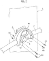
- the middle gripper 4 is formed to pass the charging cable 2 therethrough and has a cylindrical part 41 that is put on a hook 5 arranged on the charging stand 1.
- the middle gripper 4 also has a gripping part 42 that extends from the cylindrical part 41 and is gripped by a charging operator.
- the middle gripper 4 may be made of insulating material such as plastics. Also, as illustrated in Fig. 2 , the middle gripper 4 may be made of left and right divided members divided along an axial direction of the charging cable. Namely, as illustrated in Figs. 2 and 3 , the divided members may be fixed together with bolts 44 and nuts 45 so that the cylindrical part 41 may cover the charging cable 2 to pass therethrough. In this way, the middle gripper 4 is attached to the charging cable 2. It is naturally possible to attach the middle gripper 4 to the charging cable 2 according to prior known techniques.
- the charging cable 2 may have deformed part where the frictional force (pressing force) acts and undeformed part where no frictional force (pressing force) acts. Movement of the cylindrical part 41 in the axial direction of the charging cable 2 is substantially unable to deform the undeformed part. This prevents the cylindrical part 41 from moving in the axial direction of the charging cable 2.
- a frictional force threshold to establish such a state is dependent on the surface characteristics of the cylindrical part 41 and charging cable 2, such as surface elasticity and frictional coefficient. Namely, the surface characteristics of the cylindrical part 41 and charging cable 2 must be considered when determining the fastening force between the bolts 44 and the nuts 45. Attaching the cylindrical part 41 to the charging cable 2 in such a way results in preventing the cylindrical part 41 from moving in the axial direction of the charging cable 2.
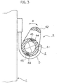
- the cylindrical part 41 is turnable around an axis of the charging cable 2 even when a movement of the cylindrical part 41 in the axial direction of the charging cable 2 is restricted. If the cylindrical part 41 is turnable in directions indicated with an arrow R in Fig. 3 , the middle gripper 4 can be put on the hook 5 with the gripping part 42 being inclined in a direction opposite to the charging stand 1. This allows the charging operator to easily grasp the gripping part 42 at the time of next charging operation. To make the cylindrical part 41 turnable, the surface characteristics of the cylindrical part 41 and charging cable 2 must be considered like the above-mentioned case when adjusting the fastening force between the bolts 44 and the nuts 45.
- annular irregular part 43 to receive the hook 5 when the cylindrical part 41 is put on the hook 5.
- annular irregular part 43 prevents the cylindrical part 41 from sideslipping and stabilizes the cylindrical part 41.
- the cylindrical part 41 may have a plurality of such annular irregular parts. It is preferable that the plurality of annular irregular parts are arranged to receive, respectively, a plurality of hooks arranged at intervals on the charging stand. This further stabilizes the cylindrical part 41.
- Figure 2 illustrates an example with a single hook 5 and Fig. 4 an example with two hooks 5 spaced from each other.
- Fig. 4 there are a plurality of the annular irregular parts 43 corresponding to the hooks 5, respectively.
- the number is not limited to two but it may be plural more than two.
- the gripping part 42 has, as illustrated in Fig. 2 , a shape so that the charging operator can grasp it when the cylindrical part 41 is on the hook 5.
- the gripping part 42 is shaped to upwardly extend from each end of the cylindrical part 41 and be joined together.
- the shape is not limited to this. Any shape is adoptable for the gripping part 42 if the shape allows the charging operator to grasp the gripping part 42 and put the same on the hook.
- the gripping part 42 may have a cantilever shape that upwardly extends from one end of the cylindrical part 41.
- a charging operation will be explained.
- the charging connector 3 arranged at the front end of the charging cable 2 is stored, as illustrated in Fig. 5 , in the predetermined part on the front face of the charging stand 1.
- the cylindrical part 41 of the middle gripper 4 attached to the charging cable 2 is put on the hook 5 on the side face of the charging stand 1 and the charging cable 2 is wound in spirals.
- the charging operator removes with one hand the charging connector 3 from the predetermined part, holds with the other hand the gripping part 42 of the middle gripper 4, and removes the cylindrical part 41 from the hook 5. In this way, the charging operator holds the front end of the charging cable with one hand and grasps the charging cable with the other hand.
- the charging cable 2 that passes large power of high voltage is required to have a voltage withstanding characteristic corresponding to the large power and strength. Accordingly, the charging cable that satisfies such requirements tends to be thick, hard, and heavy.
- the middle gripper 4 of the embodiment the charging operator is able to efficiently hold the charging cable 2 with both hands. This allows the charging operator to easily attach the charging connector 3 to the power supply inlet V1 of the electric vehicle V. Even if the charging cable 2 is wound in spirals, the charging cable 2 can be held with the middle gripper 4 to easily cancel the twists of the charging cable 2.
- the charging operator cancels the twists of the charging cable 2 by, for example, turning himself or herself, extends the charging cable 2, and attaches the charging connector 3 to the power supply inlet V1 of the electric vehicle V. Thereafter, the charging operator removes his or her hand from the middle gripper 4 and pushes the charging start button on the charging stand 1 to start charging.
- the charging operator holds the charging connector 3 with one hand and grasps the gripping part 42 of the middle gripper 4 with the other hand.
- the charging operator removes the charging connector 3 from the power supply inlet V1, winds the charging cable 2 into spirals again, stores the charging connector 3 in the predetermined part on the charging stand 1, and puts the cylindrical part 41 of the middle gripper 4 on the hook 5.
- the charging cable 2 that is thick, hard, and heavy improves its workability and operability so that, even if the charging operator is weak, he or she can easily carry out the charging operation.
- the charging cable 2 is wound into spirals and the cylindrical part 41 of the middle gripper 4 is put on the hook 5 so that the charging cable 2 is not soiled by touching the ground.
- the cylindrical part 41 of the middle gripper 4 has the annular irregular part 43 that receives the hook 5 when the cylindrical part 41 is put on the hook 5. This prevents the cylindrical part 41 from dropping off the hook 5 even if some external force acts on the charging cable 2 during off charging period. Namely, stability of the middle gripper 4 on the hook 5 improves.
- the plurality of annular irregular parts 43 illustrated in Fig. 4 that receive, respectively, the plurality of hooks 5 arranged at intervals on the charging stand further improve such stability.
- the cylindrical part 41 of the middle gripper 4 is turnable around the axis of the charging cable 2 by adjusting the fastening state of the bolts 44 and nuts 45.
- the cylindrical part 41 is turnable to the right side of the arrow R illustrated in Fig. 3 . This allows the charging operator to easily grasp the gripping part 42 at the next charging operation.
- the middle gripper for a charging cable allows a charging operator to grasp the charging connector with one hand and the middle gripper attached to the charging cable with the other hand and conduct a charging operation. This improves operability of the charging operation.
Landscapes
- Engineering & Computer Science (AREA)
- Mechanical Engineering (AREA)
- Power Engineering (AREA)
- Transportation (AREA)
- General Engineering & Computer Science (AREA)
- Electric Propulsion And Braking For Vehicles (AREA)
- Charge And Discharge Circuits For Batteries Or The Like (AREA)
Applications Claiming Priority (2)
| Application Number | Priority Date | Filing Date | Title |
|---|---|---|---|
| JP2011197763A JP5392327B2 (ja) | 2011-09-11 | 2011-09-11 | 充電ケーブルの中間把持具 |
| PCT/JP2012/072376 WO2013035673A1 (ja) | 2011-09-11 | 2012-09-03 | 充電ケーブルの中間把持具 |
Publications (3)
| Publication Number | Publication Date |
|---|---|
| EP2755295A1 EP2755295A1 (en) | 2014-07-16 |
| EP2755295A4 EP2755295A4 (en) | 2015-12-23 |
| EP2755295B1 true EP2755295B1 (en) | 2019-06-26 |
Family
ID=47832118
Family Applications (1)
| Application Number | Title | Priority Date | Filing Date |
|---|---|---|---|
| EP12829894.0A Active EP2755295B1 (en) | 2011-09-11 | 2012-09-03 | Intermediate grasping tool of charging cable |
Country Status (5)
| Country | Link |
|---|---|
| US (1) | US10072774B2 (enExample) |
| EP (1) | EP2755295B1 (enExample) |
| JP (1) | JP5392327B2 (enExample) |
| CN (1) | CN103782473B (enExample) |
| WO (1) | WO2013035673A1 (enExample) |
Families Citing this family (7)
| Publication number | Priority date | Publication date | Assignee | Title |
|---|---|---|---|---|
| JP2013179756A (ja) * | 2012-02-28 | 2013-09-09 | Denso Corp | 充電ケーブル装置 |
| JP5955702B2 (ja) * | 2012-08-27 | 2016-07-20 | 株式会社デンソー | 充電装置 |
| JP6421466B2 (ja) * | 2014-06-11 | 2018-11-14 | 三菱自動車工業株式会社 | 車両の充電ケーブル |
| DE102018100830A1 (de) | 2018-01-16 | 2019-07-18 | Dr. Ing. H.C. F. Porsche Aktiengesellschaft | Ladekabel für eine Ladesäule und Ladesäule mit einem solchen Ladekabel |
| DE102018100826A1 (de) | 2018-01-16 | 2019-07-18 | Dr. Ing. H.C. F. Porsche Aktiengesellschaft | Ladekabel und Verfahren zum Laden eines Elektroautos |
| CN109305056B (zh) * | 2018-08-27 | 2020-08-14 | 孝感锐创机械科技有限公司 | 长度可调的新能源汽车充电线装置 |
| JP7415326B2 (ja) * | 2019-03-15 | 2024-01-17 | 株式会社Gsユアサ | ケーブルの把持具 |
Family Cites Families (19)
| Publication number | Priority date | Publication date | Assignee | Title |
|---|---|---|---|---|
| US3211828A (en) * | 1963-03-28 | 1965-10-12 | Whitaker Cable Corp | Protective and latching clip for wiring harness |
| JPS55147369U (enExample) * | 1979-04-10 | 1980-10-23 | ||
| DE2918705C2 (de) * | 1979-05-09 | 1982-11-25 | Wolf-Geräte GmbH, 5240 Betzdorf | Kabelhalter zum Aufhängen eines Netzkabels am Führungsgriff eines Elektrorasenmähers |
| GB2195161A (en) * | 1986-09-12 | 1988-03-30 | Ford Motor Co | Cable clip |
| GB9021971D0 (en) * | 1990-10-09 | 1990-11-21 | Tomkins Brian E | Electrically powered mechanised floor cleaning brush |
| JPH0662280U (ja) * | 1993-02-08 | 1994-09-02 | けい子 松井 | ホーススタンド |
| JP2916348B2 (ja) * | 1993-07-22 | 1999-07-05 | 住友電装株式会社 | 電気自動車充電用コネクタ |
| US5511442A (en) * | 1994-09-02 | 1996-04-30 | Atoma International, Inc. | Control system with bowden wire assembly end clip |
| US5639049A (en) * | 1996-05-08 | 1997-06-17 | Jennings; Gilbert M. | Compact cable clip for retainment of cables and tubing |
| JP2001169467A (ja) * | 1999-12-08 | 2001-06-22 | Toyota Autom Loom Works Ltd | 充電装置 |
| JP3083658U (ja) * | 2001-07-26 | 2002-02-08 | アイリスオーヤマ株式会社 | ホースガイド用補助具 |
| US6581791B2 (en) * | 2001-08-22 | 2003-06-24 | New York Air Brake | Mounting block assembly for electrical interconnection between rail cars |
| US6595472B1 (en) * | 2001-12-28 | 2003-07-22 | Preformed Line Products Company | Cable clamp |
| JP2004215872A (ja) * | 2003-01-15 | 2004-08-05 | Mitsubishi Electric Corp | 電気掃除機 |
| JP2010114988A (ja) | 2008-11-05 | 2010-05-20 | Denso Corp | 車両用充電装置および車両用充電システム |
| JP5362367B2 (ja) * | 2009-01-09 | 2013-12-11 | 株式会社アルファ | 充電ケーブルの連結構造 |
| JP5421745B2 (ja) * | 2009-11-26 | 2014-02-19 | Ihi運搬機械株式会社 | 充電機能付き駐車装置 |
| WO2012148597A1 (en) * | 2011-04-29 | 2012-11-01 | Electric Transportation Engineering Corporation, D/B/A Ecotality North America | Device to facilitate moving an electrical cable of an electric vehicle charging station and method of providing the same |
| JP5467654B2 (ja) * | 2011-03-10 | 2014-04-09 | 株式会社豊田自動織機 | 車両用充電装置 |
-
2011
- 2011-09-11 JP JP2011197763A patent/JP5392327B2/ja active Active
-
2012
- 2012-09-03 WO PCT/JP2012/072376 patent/WO2013035673A1/ja not_active Ceased
- 2012-09-03 US US14/343,874 patent/US10072774B2/en active Active
- 2012-09-03 EP EP12829894.0A patent/EP2755295B1/en active Active
- 2012-09-03 CN CN201280042969.4A patent/CN103782473B/zh active Active
Non-Patent Citations (1)
| Title |
|---|
| None * |
Also Published As
| Publication number | Publication date |
|---|---|
| WO2013035673A1 (ja) | 2013-03-14 |
| EP2755295A4 (en) | 2015-12-23 |
| JP5392327B2 (ja) | 2014-01-22 |
| EP2755295A1 (en) | 2014-07-16 |
| CN103782473B (zh) | 2016-06-15 |
| CN103782473A (zh) | 2014-05-07 |
| US20140209354A1 (en) | 2014-07-31 |
| JP2013062891A (ja) | 2013-04-04 |
| US10072774B2 (en) | 2018-09-11 |
Similar Documents
| Publication | Publication Date | Title |
|---|---|---|
| EP2755295B1 (en) | Intermediate grasping tool of charging cable | |
| CN111884127B (zh) | 一种电力工程用预绞丝护线条自动安装设备 | |
| US8156639B1 (en) | Portable battery operated motorized racking tool | |
| CN206834426U (zh) | 一种防拉扯线束接头 | |
| KR20180001337U (ko) | 전기자동차 충전기용 자동 릴 장치 | |
| JP5208803B2 (ja) | 電線接続器具 | |
| US20120279362A1 (en) | Powered Bolt-Through Tourque Wrench | |
| JP2012010561A (ja) | 充電設備 | |
| JP5467654B2 (ja) | 車両用充電装置 | |
| US11571802B2 (en) | Electric power tool | |
| US9463965B2 (en) | Pulling tool | |
| JP5964346B2 (ja) | 間接活線工具用検電器 | |
| JP2013541824A (ja) | バックシェルに電気ケーブルのシールドを取り付けるための取付けリング | |
| JP6305189B2 (ja) | 電気自動車充放電装置 | |
| CA2432462C (en) | Safety devices for insulative tools | |
| JP6507752B2 (ja) | 電線用端末キャップ | |
| JP2011023133A (ja) | 電気プラグ | |
| CN211233053U (zh) | 一种便于搬运的电器设备及电热油汀取暖器 | |
| CN103771277B (zh) | 张力发生装置 | |
| JP5566847B2 (ja) | ナット | |
| CN222980570U (zh) | 一种温控电池连接线结构 | |
| CN212798994U (zh) | 低压无机矿物绝缘柔性耐火电缆 | |
| CN209785640U (zh) | 一种膜包高压线绕线设备 | |
| CN223013033U (zh) | 一种电动扳手 | |
| JP2014045612A (ja) | 養生カバー付きアースフック |
Legal Events
| Date | Code | Title | Description |
|---|---|---|---|
| PUAI | Public reference made under article 153(3) epc to a published international application that has entered the european phase |
Free format text: ORIGINAL CODE: 0009012 |
|
| 17P | Request for examination filed |
Effective date: 20140409 |
|
| AK | Designated contracting states |
Kind code of ref document: A1 Designated state(s): AL AT BE BG CH CY CZ DE DK EE ES FI FR GB GR HR HU IE IS IT LI LT LU LV MC MK MT NL NO PL PT RO RS SE SI SK SM TR |
|
| DAX | Request for extension of the european patent (deleted) | ||
| RA4 | Supplementary search report drawn up and despatched (corrected) |
Effective date: 20151124 |
|
| RIC1 | Information provided on ipc code assigned before grant |
Ipc: H02J 7/00 20060101AFI20151118BHEP Ipc: B60L 11/18 20060101ALI20151118BHEP |
|
| REG | Reference to a national code |
Ref country code: DE Ref legal event code: R079 Ref document number: 602012061508 Country of ref document: DE Free format text: PREVIOUS MAIN CLASS: H02J0007000000 Ipc: B60L0053160000 |
|
| GRAP | Despatch of communication of intention to grant a patent |
Free format text: ORIGINAL CODE: EPIDOSNIGR1 |
|
| STAA | Information on the status of an ep patent application or granted ep patent |
Free format text: STATUS: GRANT OF PATENT IS INTENDED |
|
| RIC1 | Information provided on ipc code assigned before grant |
Ipc: F16L 3/01 20060101ALI20190306BHEP Ipc: B60L 53/31 20190101ALI20190306BHEP Ipc: B60L 53/18 20190101ALI20190306BHEP Ipc: B60L 53/16 20190101AFI20190306BHEP |
|
| INTG | Intention to grant announced |
Effective date: 20190403 |
|
| GRAS | Grant fee paid |
Free format text: ORIGINAL CODE: EPIDOSNIGR3 |
|
| GRAA | (expected) grant |
Free format text: ORIGINAL CODE: 0009210 |
|
| STAA | Information on the status of an ep patent application or granted ep patent |
Free format text: STATUS: THE PATENT HAS BEEN GRANTED |
|
| AK | Designated contracting states |
Kind code of ref document: B1 Designated state(s): AL AT BE BG CH CY CZ DE DK EE ES FI FR GB GR HR HU IE IS IT LI LT LU LV MC MK MT NL NO PL PT RO RS SE SI SK SM TR |
|
| RAP1 | Party data changed (applicant data changed or rights of an application transferred) |
Owner name: NISSAN MOTOR CO., LTD. |
|
| REG | Reference to a national code |
Ref country code: GB Ref legal event code: FG4D |
|
| REG | Reference to a national code |
Ref country code: CH Ref legal event code: EP |
|
| REG | Reference to a national code |
Ref country code: AT Ref legal event code: REF Ref document number: 1147897 Country of ref document: AT Kind code of ref document: T Effective date: 20190715 |
|
| REG | Reference to a national code |
Ref country code: DE Ref legal event code: R096 Ref document number: 602012061508 Country of ref document: DE |
|
| REG | Reference to a national code |
Ref country code: IE Ref legal event code: FG4D |
|
| REG | Reference to a national code |
Ref country code: NL Ref legal event code: MP Effective date: 20190626 |
|
| PG25 | Lapsed in a contracting state [announced via postgrant information from national office to epo] |
Ref country code: FI Free format text: LAPSE BECAUSE OF FAILURE TO SUBMIT A TRANSLATION OF THE DESCRIPTION OR TO PAY THE FEE WITHIN THE PRESCRIBED TIME-LIMIT Effective date: 20190626 Ref country code: NO Free format text: LAPSE BECAUSE OF FAILURE TO SUBMIT A TRANSLATION OF THE DESCRIPTION OR TO PAY THE FEE WITHIN THE PRESCRIBED TIME-LIMIT Effective date: 20190926 Ref country code: LT Free format text: LAPSE BECAUSE OF FAILURE TO SUBMIT A TRANSLATION OF THE DESCRIPTION OR TO PAY THE FEE WITHIN THE PRESCRIBED TIME-LIMIT Effective date: 20190626 Ref country code: HR Free format text: LAPSE BECAUSE OF FAILURE TO SUBMIT A TRANSLATION OF THE DESCRIPTION OR TO PAY THE FEE WITHIN THE PRESCRIBED TIME-LIMIT Effective date: 20190626 Ref country code: AL Free format text: LAPSE BECAUSE OF FAILURE TO SUBMIT A TRANSLATION OF THE DESCRIPTION OR TO PAY THE FEE WITHIN THE PRESCRIBED TIME-LIMIT Effective date: 20190626 Ref country code: SE Free format text: LAPSE BECAUSE OF FAILURE TO SUBMIT A TRANSLATION OF THE DESCRIPTION OR TO PAY THE FEE WITHIN THE PRESCRIBED TIME-LIMIT Effective date: 20190626 |
|
| REG | Reference to a national code |
Ref country code: LT Ref legal event code: MG4D |
|
| PG25 | Lapsed in a contracting state [announced via postgrant information from national office to epo] |
Ref country code: GR Free format text: LAPSE BECAUSE OF FAILURE TO SUBMIT A TRANSLATION OF THE DESCRIPTION OR TO PAY THE FEE WITHIN THE PRESCRIBED TIME-LIMIT Effective date: 20190927 Ref country code: LV Free format text: LAPSE BECAUSE OF FAILURE TO SUBMIT A TRANSLATION OF THE DESCRIPTION OR TO PAY THE FEE WITHIN THE PRESCRIBED TIME-LIMIT Effective date: 20190626 Ref country code: RS Free format text: LAPSE BECAUSE OF FAILURE TO SUBMIT A TRANSLATION OF THE DESCRIPTION OR TO PAY THE FEE WITHIN THE PRESCRIBED TIME-LIMIT Effective date: 20190626 Ref country code: BG Free format text: LAPSE BECAUSE OF FAILURE TO SUBMIT A TRANSLATION OF THE DESCRIPTION OR TO PAY THE FEE WITHIN THE PRESCRIBED TIME-LIMIT Effective date: 20190926 |
|
| REG | Reference to a national code |
Ref country code: AT Ref legal event code: MK05 Ref document number: 1147897 Country of ref document: AT Kind code of ref document: T Effective date: 20190626 |
|
| PG25 | Lapsed in a contracting state [announced via postgrant information from national office to epo] |
Ref country code: RO Free format text: LAPSE BECAUSE OF FAILURE TO SUBMIT A TRANSLATION OF THE DESCRIPTION OR TO PAY THE FEE WITHIN THE PRESCRIBED TIME-LIMIT Effective date: 20190626 Ref country code: SK Free format text: LAPSE BECAUSE OF FAILURE TO SUBMIT A TRANSLATION OF THE DESCRIPTION OR TO PAY THE FEE WITHIN THE PRESCRIBED TIME-LIMIT Effective date: 20190626 Ref country code: CZ Free format text: LAPSE BECAUSE OF FAILURE TO SUBMIT A TRANSLATION OF THE DESCRIPTION OR TO PAY THE FEE WITHIN THE PRESCRIBED TIME-LIMIT Effective date: 20190626 Ref country code: PT Free format text: LAPSE BECAUSE OF FAILURE TO SUBMIT A TRANSLATION OF THE DESCRIPTION OR TO PAY THE FEE WITHIN THE PRESCRIBED TIME-LIMIT Effective date: 20191028 Ref country code: AT Free format text: LAPSE BECAUSE OF FAILURE TO SUBMIT A TRANSLATION OF THE DESCRIPTION OR TO PAY THE FEE WITHIN THE PRESCRIBED TIME-LIMIT Effective date: 20190626 Ref country code: NL Free format text: LAPSE BECAUSE OF FAILURE TO SUBMIT A TRANSLATION OF THE DESCRIPTION OR TO PAY THE FEE WITHIN THE PRESCRIBED TIME-LIMIT Effective date: 20190626 Ref country code: EE Free format text: LAPSE BECAUSE OF FAILURE TO SUBMIT A TRANSLATION OF THE DESCRIPTION OR TO PAY THE FEE WITHIN THE PRESCRIBED TIME-LIMIT Effective date: 20190626 |
|
| PG25 | Lapsed in a contracting state [announced via postgrant information from national office to epo] |
Ref country code: IT Free format text: LAPSE BECAUSE OF FAILURE TO SUBMIT A TRANSLATION OF THE DESCRIPTION OR TO PAY THE FEE WITHIN THE PRESCRIBED TIME-LIMIT Effective date: 20190626 Ref country code: ES Free format text: LAPSE BECAUSE OF FAILURE TO SUBMIT A TRANSLATION OF THE DESCRIPTION OR TO PAY THE FEE WITHIN THE PRESCRIBED TIME-LIMIT Effective date: 20190626 Ref country code: SM Free format text: LAPSE BECAUSE OF FAILURE TO SUBMIT A TRANSLATION OF THE DESCRIPTION OR TO PAY THE FEE WITHIN THE PRESCRIBED TIME-LIMIT Effective date: 20190626 Ref country code: IS Free format text: LAPSE BECAUSE OF FAILURE TO SUBMIT A TRANSLATION OF THE DESCRIPTION OR TO PAY THE FEE WITHIN THE PRESCRIBED TIME-LIMIT Effective date: 20191026 |
|
| PG25 | Lapsed in a contracting state [announced via postgrant information from national office to epo] |
Ref country code: TR Free format text: LAPSE BECAUSE OF FAILURE TO SUBMIT A TRANSLATION OF THE DESCRIPTION OR TO PAY THE FEE WITHIN THE PRESCRIBED TIME-LIMIT Effective date: 20190626 |
|
| PG25 | Lapsed in a contracting state [announced via postgrant information from national office to epo] |
Ref country code: PL Free format text: LAPSE BECAUSE OF FAILURE TO SUBMIT A TRANSLATION OF THE DESCRIPTION OR TO PAY THE FEE WITHIN THE PRESCRIBED TIME-LIMIT Effective date: 20190626 Ref country code: DK Free format text: LAPSE BECAUSE OF FAILURE TO SUBMIT A TRANSLATION OF THE DESCRIPTION OR TO PAY THE FEE WITHIN THE PRESCRIBED TIME-LIMIT Effective date: 20190626 |
|
| PG25 | Lapsed in a contracting state [announced via postgrant information from national office to epo] |
Ref country code: IS Free format text: LAPSE BECAUSE OF FAILURE TO SUBMIT A TRANSLATION OF THE DESCRIPTION OR TO PAY THE FEE WITHIN THE PRESCRIBED TIME-LIMIT Effective date: 20200224 Ref country code: MC Free format text: LAPSE BECAUSE OF FAILURE TO SUBMIT A TRANSLATION OF THE DESCRIPTION OR TO PAY THE FEE WITHIN THE PRESCRIBED TIME-LIMIT Effective date: 20190626 |
|
| REG | Reference to a national code |
Ref country code: CH Ref legal event code: PL |
|
| REG | Reference to a national code |
Ref country code: DE Ref legal event code: R097 Ref document number: 602012061508 Country of ref document: DE |
|
| PLBE | No opposition filed within time limit |
Free format text: ORIGINAL CODE: 0009261 |
|
| STAA | Information on the status of an ep patent application or granted ep patent |
Free format text: STATUS: NO OPPOSITION FILED WITHIN TIME LIMIT |
|
| PG2D | Information on lapse in contracting state deleted |
Ref country code: IS |
|
| PG25 | Lapsed in a contracting state [announced via postgrant information from national office to epo] |
Ref country code: LI Free format text: LAPSE BECAUSE OF NON-PAYMENT OF DUE FEES Effective date: 20190930 Ref country code: IE Free format text: LAPSE BECAUSE OF NON-PAYMENT OF DUE FEES Effective date: 20190903 Ref country code: CH Free format text: LAPSE BECAUSE OF NON-PAYMENT OF DUE FEES Effective date: 20190930 Ref country code: LU Free format text: LAPSE BECAUSE OF NON-PAYMENT OF DUE FEES Effective date: 20190903 |
|
| 26N | No opposition filed |
Effective date: 20200603 |
|
| REG | Reference to a national code |
Ref country code: BE Ref legal event code: MM Effective date: 20190930 |
|
| PG25 | Lapsed in a contracting state [announced via postgrant information from national office to epo] |
Ref country code: SI Free format text: LAPSE BECAUSE OF FAILURE TO SUBMIT A TRANSLATION OF THE DESCRIPTION OR TO PAY THE FEE WITHIN THE PRESCRIBED TIME-LIMIT Effective date: 20190626 Ref country code: BE Free format text: LAPSE BECAUSE OF NON-PAYMENT OF DUE FEES Effective date: 20190930 |
|
| PG25 | Lapsed in a contracting state [announced via postgrant information from national office to epo] |
Ref country code: CY Free format text: LAPSE BECAUSE OF FAILURE TO SUBMIT A TRANSLATION OF THE DESCRIPTION OR TO PAY THE FEE WITHIN THE PRESCRIBED TIME-LIMIT Effective date: 20190626 |
|
| PG25 | Lapsed in a contracting state [announced via postgrant information from national office to epo] |
Ref country code: HU Free format text: LAPSE BECAUSE OF FAILURE TO SUBMIT A TRANSLATION OF THE DESCRIPTION OR TO PAY THE FEE WITHIN THE PRESCRIBED TIME-LIMIT; INVALID AB INITIO Effective date: 20120903 Ref country code: MT Free format text: LAPSE BECAUSE OF FAILURE TO SUBMIT A TRANSLATION OF THE DESCRIPTION OR TO PAY THE FEE WITHIN THE PRESCRIBED TIME-LIMIT Effective date: 20190626 |
|
| PG25 | Lapsed in a contracting state [announced via postgrant information from national office to epo] |
Ref country code: MK Free format text: LAPSE BECAUSE OF FAILURE TO SUBMIT A TRANSLATION OF THE DESCRIPTION OR TO PAY THE FEE WITHIN THE PRESCRIBED TIME-LIMIT Effective date: 20190626 |
|
| PGFP | Annual fee paid to national office [announced via postgrant information from national office to epo] |
Ref country code: DE Payment date: 20240820 Year of fee payment: 13 |
|
| PGFP | Annual fee paid to national office [announced via postgrant information from national office to epo] |
Ref country code: GB Payment date: 20240820 Year of fee payment: 13 |
|
| PGFP | Annual fee paid to national office [announced via postgrant information from national office to epo] |
Ref country code: FR Payment date: 20240820 Year of fee payment: 13 |