WO2013035155A1 - 内燃機関の排気浄化装置 - Google Patents
内燃機関の排気浄化装置 Download PDFInfo
- Publication number
- WO2013035155A1 WO2013035155A1 PCT/JP2011/070243 JP2011070243W WO2013035155A1 WO 2013035155 A1 WO2013035155 A1 WO 2013035155A1 JP 2011070243 W JP2011070243 W JP 2011070243W WO 2013035155 A1 WO2013035155 A1 WO 2013035155A1
- Authority
- WO
- WIPO (PCT)
- Prior art keywords
- nox
- catalyst
- internal combustion
- combustion engine
- deterioration
- Prior art date
Links
Images
Classifications
-
- F—MECHANICAL ENGINEERING; LIGHTING; HEATING; WEAPONS; BLASTING
- F01—MACHINES OR ENGINES IN GENERAL; ENGINE PLANTS IN GENERAL; STEAM ENGINES
- F01N—GAS-FLOW SILENCERS OR EXHAUST APPARATUS FOR MACHINES OR ENGINES IN GENERAL; GAS-FLOW SILENCERS OR EXHAUST APPARATUS FOR INTERNAL COMBUSTION ENGINES
- F01N3/00—Exhaust or silencing apparatus having means for purifying, rendering innocuous, or otherwise treating exhaust
- F01N3/08—Exhaust or silencing apparatus having means for purifying, rendering innocuous, or otherwise treating exhaust for rendering innocuous
- F01N3/0807—Exhaust or silencing apparatus having means for purifying, rendering innocuous, or otherwise treating exhaust for rendering innocuous by using absorbents or adsorbents
- F01N3/0814—Exhaust or silencing apparatus having means for purifying, rendering innocuous, or otherwise treating exhaust for rendering innocuous by using absorbents or adsorbents combined with catalytic converters, e.g. NOx absorption/storage reduction catalysts
-
- F—MECHANICAL ENGINEERING; LIGHTING; HEATING; WEAPONS; BLASTING
- F01—MACHINES OR ENGINES IN GENERAL; ENGINE PLANTS IN GENERAL; STEAM ENGINES
- F01N—GAS-FLOW SILENCERS OR EXHAUST APPARATUS FOR MACHINES OR ENGINES IN GENERAL; GAS-FLOW SILENCERS OR EXHAUST APPARATUS FOR INTERNAL COMBUSTION ENGINES
- F01N3/00—Exhaust or silencing apparatus having means for purifying, rendering innocuous, or otherwise treating exhaust
- F01N3/08—Exhaust or silencing apparatus having means for purifying, rendering innocuous, or otherwise treating exhaust for rendering innocuous
- F01N3/10—Exhaust or silencing apparatus having means for purifying, rendering innocuous, or otherwise treating exhaust for rendering innocuous by thermal or catalytic conversion of noxious components of exhaust
- F01N3/18—Exhaust or silencing apparatus having means for purifying, rendering innocuous, or otherwise treating exhaust for rendering innocuous by thermal or catalytic conversion of noxious components of exhaust characterised by methods of operation; Control
- F01N3/20—Exhaust or silencing apparatus having means for purifying, rendering innocuous, or otherwise treating exhaust for rendering innocuous by thermal or catalytic conversion of noxious components of exhaust characterised by methods of operation; Control specially adapted for catalytic conversion ; Methods of operation or control of catalytic converters
- F01N3/2053—By-passing catalytic reactors, e.g. to prevent overheating
-
- F—MECHANICAL ENGINEERING; LIGHTING; HEATING; WEAPONS; BLASTING
- F01—MACHINES OR ENGINES IN GENERAL; ENGINE PLANTS IN GENERAL; STEAM ENGINES
- F01N—GAS-FLOW SILENCERS OR EXHAUST APPARATUS FOR MACHINES OR ENGINES IN GENERAL; GAS-FLOW SILENCERS OR EXHAUST APPARATUS FOR INTERNAL COMBUSTION ENGINES
- F01N11/00—Monitoring or diagnostic devices for exhaust-gas treatment apparatus, e.g. for catalytic activity
-
- F—MECHANICAL ENGINEERING; LIGHTING; HEATING; WEAPONS; BLASTING
- F01—MACHINES OR ENGINES IN GENERAL; ENGINE PLANTS IN GENERAL; STEAM ENGINES
- F01N—GAS-FLOW SILENCERS OR EXHAUST APPARATUS FOR MACHINES OR ENGINES IN GENERAL; GAS-FLOW SILENCERS OR EXHAUST APPARATUS FOR INTERNAL COMBUSTION ENGINES
- F01N3/00—Exhaust or silencing apparatus having means for purifying, rendering innocuous, or otherwise treating exhaust
- F01N3/08—Exhaust or silencing apparatus having means for purifying, rendering innocuous, or otherwise treating exhaust for rendering innocuous
- F01N3/0807—Exhaust or silencing apparatus having means for purifying, rendering innocuous, or otherwise treating exhaust for rendering innocuous by using absorbents or adsorbents
- F01N3/0871—Regulation of absorbents or adsorbents, e.g. purging
- F01N3/0885—Regeneration of deteriorated absorbents or adsorbents, e.g. desulfurization of NOx traps
-
- F—MECHANICAL ENGINEERING; LIGHTING; HEATING; WEAPONS; BLASTING
- F01—MACHINES OR ENGINES IN GENERAL; ENGINE PLANTS IN GENERAL; STEAM ENGINES
- F01N—GAS-FLOW SILENCERS OR EXHAUST APPARATUS FOR MACHINES OR ENGINES IN GENERAL; GAS-FLOW SILENCERS OR EXHAUST APPARATUS FOR INTERNAL COMBUSTION ENGINES
- F01N3/00—Exhaust or silencing apparatus having means for purifying, rendering innocuous, or otherwise treating exhaust
- F01N3/08—Exhaust or silencing apparatus having means for purifying, rendering innocuous, or otherwise treating exhaust for rendering innocuous
- F01N3/10—Exhaust or silencing apparatus having means for purifying, rendering innocuous, or otherwise treating exhaust for rendering innocuous by thermal or catalytic conversion of noxious components of exhaust
- F01N3/18—Exhaust or silencing apparatus having means for purifying, rendering innocuous, or otherwise treating exhaust for rendering innocuous by thermal or catalytic conversion of noxious components of exhaust characterised by methods of operation; Control
- F01N3/20—Exhaust or silencing apparatus having means for purifying, rendering innocuous, or otherwise treating exhaust for rendering innocuous by thermal or catalytic conversion of noxious components of exhaust characterised by methods of operation; Control specially adapted for catalytic conversion ; Methods of operation or control of catalytic converters
- F01N3/2066—Selective catalytic reduction [SCR]
- F01N3/2073—Selective catalytic reduction [SCR] with means for generating a reducing substance from the exhaust gases
-
- F—MECHANICAL ENGINEERING; LIGHTING; HEATING; WEAPONS; BLASTING
- F01—MACHINES OR ENGINES IN GENERAL; ENGINE PLANTS IN GENERAL; STEAM ENGINES
- F01N—GAS-FLOW SILENCERS OR EXHAUST APPARATUS FOR MACHINES OR ENGINES IN GENERAL; GAS-FLOW SILENCERS OR EXHAUST APPARATUS FOR INTERNAL COMBUSTION ENGINES
- F01N13/00—Exhaust or silencing apparatus characterised by constructional features ; Exhaust or silencing apparatus, or parts thereof, having pertinent characteristics not provided for in, or of interest apart from, groups F01N1/00 - F01N5/00, F01N9/00, F01N11/00
- F01N13/009—Exhaust or silencing apparatus characterised by constructional features ; Exhaust or silencing apparatus, or parts thereof, having pertinent characteristics not provided for in, or of interest apart from, groups F01N1/00 - F01N5/00, F01N9/00, F01N11/00 having two or more separate purifying devices arranged in series
-
- F—MECHANICAL ENGINEERING; LIGHTING; HEATING; WEAPONS; BLASTING
- F01—MACHINES OR ENGINES IN GENERAL; ENGINE PLANTS IN GENERAL; STEAM ENGINES
- F01N—GAS-FLOW SILENCERS OR EXHAUST APPARATUS FOR MACHINES OR ENGINES IN GENERAL; GAS-FLOW SILENCERS OR EXHAUST APPARATUS FOR INTERNAL COMBUSTION ENGINES
- F01N2430/00—Influencing exhaust purification, e.g. starting of catalytic reaction, filter regeneration, or the like, by controlling engine operating characteristics
- F01N2430/08—Influencing exhaust purification, e.g. starting of catalytic reaction, filter regeneration, or the like, by controlling engine operating characteristics by modifying ignition or injection timing
- F01N2430/085—Influencing exhaust purification, e.g. starting of catalytic reaction, filter regeneration, or the like, by controlling engine operating characteristics by modifying ignition or injection timing at least a part of the injection taking place during expansion or exhaust stroke
-
- F—MECHANICAL ENGINEERING; LIGHTING; HEATING; WEAPONS; BLASTING
- F01—MACHINES OR ENGINES IN GENERAL; ENGINE PLANTS IN GENERAL; STEAM ENGINES
- F01N—GAS-FLOW SILENCERS OR EXHAUST APPARATUS FOR MACHINES OR ENGINES IN GENERAL; GAS-FLOW SILENCERS OR EXHAUST APPARATUS FOR INTERNAL COMBUSTION ENGINES
- F01N2550/00—Monitoring or diagnosing the deterioration of exhaust systems
- F01N2550/02—Catalytic activity of catalytic converters
-
- F—MECHANICAL ENGINEERING; LIGHTING; HEATING; WEAPONS; BLASTING
- F01—MACHINES OR ENGINES IN GENERAL; ENGINE PLANTS IN GENERAL; STEAM ENGINES
- F01N—GAS-FLOW SILENCERS OR EXHAUST APPARATUS FOR MACHINES OR ENGINES IN GENERAL; GAS-FLOW SILENCERS OR EXHAUST APPARATUS FOR INTERNAL COMBUSTION ENGINES
- F01N2550/00—Monitoring or diagnosing the deterioration of exhaust systems
- F01N2550/03—Monitoring or diagnosing the deterioration of exhaust systems of sorbing activity of adsorbents or absorbents
-
- F—MECHANICAL ENGINEERING; LIGHTING; HEATING; WEAPONS; BLASTING
- F01—MACHINES OR ENGINES IN GENERAL; ENGINE PLANTS IN GENERAL; STEAM ENGINES
- F01N—GAS-FLOW SILENCERS OR EXHAUST APPARATUS FOR MACHINES OR ENGINES IN GENERAL; GAS-FLOW SILENCERS OR EXHAUST APPARATUS FOR INTERNAL COMBUSTION ENGINES
- F01N2560/00—Exhaust systems with means for detecting or measuring exhaust gas components or characteristics
- F01N2560/06—Exhaust systems with means for detecting or measuring exhaust gas components or characteristics the means being a temperature sensor
-
- F—MECHANICAL ENGINEERING; LIGHTING; HEATING; WEAPONS; BLASTING
- F01—MACHINES OR ENGINES IN GENERAL; ENGINE PLANTS IN GENERAL; STEAM ENGINES
- F01N—GAS-FLOW SILENCERS OR EXHAUST APPARATUS FOR MACHINES OR ENGINES IN GENERAL; GAS-FLOW SILENCERS OR EXHAUST APPARATUS FOR INTERNAL COMBUSTION ENGINES
- F01N2560/00—Exhaust systems with means for detecting or measuring exhaust gas components or characteristics
- F01N2560/14—Exhaust systems with means for detecting or measuring exhaust gas components or characteristics having more than one sensor of one kind
-
- F—MECHANICAL ENGINEERING; LIGHTING; HEATING; WEAPONS; BLASTING
- F01—MACHINES OR ENGINES IN GENERAL; ENGINE PLANTS IN GENERAL; STEAM ENGINES
- F01N—GAS-FLOW SILENCERS OR EXHAUST APPARATUS FOR MACHINES OR ENGINES IN GENERAL; GAS-FLOW SILENCERS OR EXHAUST APPARATUS FOR INTERNAL COMBUSTION ENGINES
- F01N2610/00—Adding substances to exhaust gases
- F01N2610/03—Adding substances to exhaust gases the substance being hydrocarbons, e.g. engine fuel
-
- F—MECHANICAL ENGINEERING; LIGHTING; HEATING; WEAPONS; BLASTING
- F01—MACHINES OR ENGINES IN GENERAL; ENGINE PLANTS IN GENERAL; STEAM ENGINES
- F01N—GAS-FLOW SILENCERS OR EXHAUST APPARATUS FOR MACHINES OR ENGINES IN GENERAL; GAS-FLOW SILENCERS OR EXHAUST APPARATUS FOR INTERNAL COMBUSTION ENGINES
- F01N2900/00—Details of electrical control or of the monitoring of the exhaust gas treating apparatus
- F01N2900/06—Parameters used for exhaust control or diagnosing
- F01N2900/16—Parameters used for exhaust control or diagnosing said parameters being related to the exhaust apparatus, e.g. particulate filter or catalyst
-
- F—MECHANICAL ENGINEERING; LIGHTING; HEATING; WEAPONS; BLASTING
- F01—MACHINES OR ENGINES IN GENERAL; ENGINE PLANTS IN GENERAL; STEAM ENGINES
- F01N—GAS-FLOW SILENCERS OR EXHAUST APPARATUS FOR MACHINES OR ENGINES IN GENERAL; GAS-FLOW SILENCERS OR EXHAUST APPARATUS FOR INTERNAL COMBUSTION ENGINES
- F01N3/00—Exhaust or silencing apparatus having means for purifying, rendering innocuous, or otherwise treating exhaust
- F01N3/08—Exhaust or silencing apparatus having means for purifying, rendering innocuous, or otherwise treating exhaust for rendering innocuous
- F01N3/10—Exhaust or silencing apparatus having means for purifying, rendering innocuous, or otherwise treating exhaust for rendering innocuous by thermal or catalytic conversion of noxious components of exhaust
- F01N3/101—Three-way catalysts
-
- Y—GENERAL TAGGING OF NEW TECHNOLOGICAL DEVELOPMENTS; GENERAL TAGGING OF CROSS-SECTIONAL TECHNOLOGIES SPANNING OVER SEVERAL SECTIONS OF THE IPC; TECHNICAL SUBJECTS COVERED BY FORMER USPC CROSS-REFERENCE ART COLLECTIONS [XRACs] AND DIGESTS
- Y02—TECHNOLOGIES OR APPLICATIONS FOR MITIGATION OR ADAPTATION AGAINST CLIMATE CHANGE
- Y02T—CLIMATE CHANGE MITIGATION TECHNOLOGIES RELATED TO TRANSPORTATION
- Y02T10/00—Road transport of goods or passengers
- Y02T10/10—Internal combustion engine [ICE] based vehicles
- Y02T10/12—Improving ICE efficiencies
-
- Y—GENERAL TAGGING OF NEW TECHNOLOGICAL DEVELOPMENTS; GENERAL TAGGING OF CROSS-SECTIONAL TECHNOLOGIES SPANNING OVER SEVERAL SECTIONS OF THE IPC; TECHNICAL SUBJECTS COVERED BY FORMER USPC CROSS-REFERENCE ART COLLECTIONS [XRACs] AND DIGESTS
- Y02—TECHNOLOGIES OR APPLICATIONS FOR MITIGATION OR ADAPTATION AGAINST CLIMATE CHANGE
- Y02T—CLIMATE CHANGE MITIGATION TECHNOLOGIES RELATED TO TRANSPORTATION
- Y02T10/00—Road transport of goods or passengers
- Y02T10/10—Internal combustion engine [ICE] based vehicles
- Y02T10/40—Engine management systems
Definitions
- the present invention relates to an exhaust purification device for an internal combustion engine.
- NSR catalyst NOx storage reduction catalyst
- This NSR catalyst also stores sulfur oxides (SOx) produced by combustion of sulfur components contained in the fuel, similar to NOx.
- SOx sulfur oxides
- the stored SOx is less likely to be released than NOx and accumulates in the NSR catalyst. This is called sulfur poisoning.
- This sulfur poisoning reduces the NOx purification rate of the NSR catalyst, so it is necessary to perform a sulfur poisoning recovery process at an appropriate time.
- This sulfur poisoning recovery process is performed by causing the NSR catalyst to have a high temperature and the exhaust gas with a reduced oxygen concentration to flow through the NSR catalyst.
- a selective reduction type NOx catalyst (hereinafter also referred to as an SCR catalyst) can be provided downstream of the NSR catalyst.
- This SCR catalyst is a catalyst that selectively reduces NOx with a reducing agent.
- the NOx purification rate in this SCR catalyst is affected by the state of the NSR catalyst. That is, NH 3 that is a reducing agent for the SCR catalyst is generated in the NSR catalyst, but the amount of NH 3 generated varies depending on the state of the NSR catalyst.
- the prior art does not mention the sulfur poisoning recovery process of the NSR catalyst when the SCR catalyst is provided downstream of the NSR catalyst. For this reason, there exists a possibility that the sulfur poisoning recovery
- the present invention has been made in view of the above-described problems, and an object of the present invention is to provide a NOx storage reduction catalyst having a selective reduction NOx catalyst downstream of the NOx storage reduction catalyst. It is to maintain the NOx purification performance of the entire exhaust gas purification device regardless of the deterioration.
- an exhaust gas purification apparatus for an internal combustion engine comprises: It is provided in the exhaust passage of the internal combustion engine.
- NOx in the exhaust gas is occluded.
- the oxygen concentration of the inflowing exhaust gas decreases and the reducing agent is present, the stored NOx is removed.
- An NOx storage reduction catalyst that reduces, A selective reduction type NOx catalyst that is provided in an exhaust passage downstream of the storage reduction type NOx catalyst and selectively reduces NOx;
- a detection unit for detecting the degree of deterioration of the NOx storage reduction catalyst or the selective reduction NOx catalyst; When the degree of deterioration detected by the detection unit is low, it promotes the reduction of NOx in the NOx storage reduction catalyst than when it is high, and when the degree of deterioration detected by the detection unit is high, it is lower than when it is low.
- a control unit that promotes reduction of NOx in the selective reduction type NOx catalyst; Is provided.
- the NOx storage reduction catalyst reacts, for example, H 2 or HC with NO to generate NH 3 .
- This NH 3 can be used as a reducing agent in the selective reduction type NOx catalyst.
- the detection unit may detect the degree of deterioration based on a physical quantity correlated with the degree of deterioration of the NOx storage reduction catalyst or the selective reduction NOx catalyst.
- the storage reduction type NOx catalyst and the selective reduction type NOx catalyst have a correlation in the degree of deterioration, the degree of deterioration of either one of the catalysts may be detected.
- promoting the reduction of NOx includes facilitating reduction of NOx, increasing the NOx purification rate, enhancing the NOx purification capacity, and increasing the supply amount of the reducing agent. be able to.
- the NOx storage reduction catalyst is poisoned by sulfur components in the exhaust.
- the NOx storage reduction catalyst deteriorates due to heat or aging, and the NOx storage capacity decreases.
- the degree of deterioration of the NOx storage reduction catalyst due to heat or the like is low, the NOx storage capability is high, so SOx is also easily stored. For this reason, sulfur poisoning is likely to occur in the NOx storage reduction catalyst.
- the frequency of performing the sulfur poisoning recovery process is increased when the degree of deterioration is low than when it is high, it is possible to suppress the NOx purification rate from decreasing in the NOx storage reduction catalyst. That is, the NOx purification rate can be increased by promoting the reduction of NOx in the NOx storage reduction catalyst when the degree of deterioration of the NOx storage reduction catalyst is low than when it is high.
- the NOx storage reduction catalyst deteriorates, the SOx storage capacity decreases, so that sulfur poisoning hardly occurs. Therefore, the frequency of performing the sulfur poisoning recovery process can be reduced. Further, when the NOx storage reduction catalyst is deteriorated, the NOx storage capacity is lowered, so that the amount of NOx that can be reduced does not change much even if the frequency of performing the sulfur poisoning recovery process is reduced. Therefore, it is not necessary to promote the reduction of NOx in the NOx storage reduction catalyst.
- the selective reduction type NOx catalyst progresses more slowly than the NOx storage reduction catalyst. Therefore, even if the NOx storage reduction catalyst deteriorates, NOx can be reduced in the selective reduction NOx catalyst. However, when the NOx storage reduction catalyst deteriorates, the ability to generate NH 3 decreases, and therefore the reducing agent supplied to the selective reduction NOx catalyst can decrease.
- the reducing agent can be supplied to the selective reduction NOx catalyst, so that the NOx purification rate in the selective reduction NOx catalyst can be increased. That is, as the degree of deterioration of the catalyst increases, the reduction of NOx with the selective reduction type NOx catalyst can be promoted. As a result, the decrease in the NOx purification rate in the NOx storage reduction catalyst can be compensated by the increase in the NOx purification rate in the selective reduction type NOx catalyst, so that the NOx purification rate of the exhaust emission control device as a whole decreases. Can be suppressed.
- the control unit becomes difficult to reduce NOx with the NOx storage reduction catalyst, and NOx reduction with the selective reduction NOx catalyst becomes difficult.
- a reducing agent may be supplied to the NOx storage reduction catalyst and the selective reduction NOx catalyst.
- the control unit promotes the reduction of NOx in the NOx storage reduction catalyst as the degree of deterioration detected by the detection unit is lower, and as the degree of deterioration detected by the detection unit is higher, Reduction of NOx by the selective reduction type NOx catalyst may be promoted. Further, as the degree of deterioration detected by the detector increases, the NOx reduction priority in the selective reduction NOx catalyst may be made higher than the NOx storage reduction catalyst.
- control unit can increase the NOx concentration in the exhaust gas flowing into the NOx storage reduction catalyst as the degree of deterioration detected by the detection unit is higher.
- the production amount of NH 3 can be increased in the NOx storage reduction catalyst. That is, since the NOx in the exhaust gas is NH 3 is produced by reacting with HC or H 2 at the NOx storage reduction catalyst, by increasing the NOx concentration, it is possible to increase the production amount of NH 3. As a result, more reducing agent can be supplied to the selective reduction type NOx catalyst. Then, the reduction of NOx with the selective reduction type NOx catalyst can be promoted. Note that the higher the degree of deterioration detected by the detector, the greater the amount of NOx in the exhaust gas flowing into the NOx storage reduction catalyst.
- the controller can reduce the frequency of recovering the sulfur poisoning of the NOx storage reduction catalyst as the degree of deterioration detected by the detector is higher.
- control unit increases the amount of reducing agent supplied during NOx reduction or NH 3 generation in the NOx storage reduction catalyst as the degree of deterioration detected by the detection unit increases. be able to.
- the production amount of NH 3 can be increased in the NOx storage reduction catalyst. That is, since the NOx in the exhaust gas NH 3 reacts with HC or H 2 is generated by the NOx storage reduction catalyst, by increasing the amount of supplied reducing agent, increases the production of NH 3 be able to. As a result, more reducing agent can be supplied to the selective reduction type NOx catalyst. That is, the reduction of NOx with the selective reduction type NOx catalyst can be promoted.
- the selective reduction type NOx catalyst when the selective reduction type NOx catalyst is provided downstream of the NOx storage reduction catalyst, the NOx purification performance of the entire exhaust gas purification device is maintained regardless of the deterioration of the NOx storage reduction catalyst. be able to.
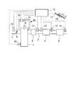
- FIG. 1 is a diagram showing a schematic configuration of an internal combustion engine according to the present embodiment and its intake system and exhaust system.
- the internal combustion engine 1 shown in FIG. 1 is a gasoline engine, but may be a diesel engine.
- the internal combustion engine 1 is mounted on a vehicle, for example.
- the exhaust passage 2 is connected to the internal combustion engine 1.
- the three-way catalyst 3 In the middle of the exhaust passage 2, in order from the upstream side, the NOx storage reduction catalyst 4 (hereinafter referred to as NSR catalyst 4), and the selective reduction NOx catalyst 5 (hereinafter referred to as SCR catalyst 5). Is provided.
- the three-way catalyst 3 purifies NOx, HC and CO with maximum efficiency when the catalyst atmosphere is at the stoichiometric air-fuel ratio.
- the three-way catalyst 3 has an oxygen storage capability. That is, by storing excess oxygen when the air-fuel ratio of the inflowing exhaust gas is a lean air-fuel ratio, and releasing the insufficient oxygen when the air-fuel ratio of the inflowing exhaust gas is rich, the exhaust gas is reduced. Purify.
- the three-way catalyst 3 can purify HC, CO, and NOx even if it is other than the stoichiometric air-fuel ratio. That is, by the action of the oxygen storage ability, it becomes possible to expand the range of the air-fuel ratio (also referred to as a purification window) in which the three-way catalyst 3 can purify HC, CO, and NOx at a predetermined ratio or more.
- a purification window also referred to as a purification window
- the NSR catalyst 4 stores NOx in the exhaust when the oxygen concentration of the inflowing exhaust gas is high, and reduces the stored NOx when the oxygen concentration of the inflowing exhaust gas decreases and a reducing agent is present. It has a function.
- HC or CO that is unburned fuel discharged from the internal combustion engine 1 can be used. Note that when the exhaust gas passes through the three-way catalyst 3 or the NSR catalyst 4, NOx in the exhaust gas may react with HC or H 2 to generate ammonia (NH 3 ).
- the SCR catalyst 5 has a function of adsorbing a reducing agent and selectively reducing NOx by the adsorbing reducing agent when NOx passes.
- a reducing agent supplied to the SCR catalyst 5 NH 3 produced by the three-way catalyst 3 or the NSR catalyst 4 can be used.
- a first temperature sensor 11 for detecting the temperature of the exhaust and an air-fuel ratio sensor 12 for detecting the air-fuel ratio of the exhaust are provided in the exhaust passage 2 downstream of the three-way catalyst 3 and upstream of the NSR catalyst. It is attached. The temperature of the three-way catalyst 3 or the temperature of the NSR catalyst 4 can be detected by the first temperature sensor 11. Further, the air-fuel ratio sensor 12 can detect the air-fuel ratio of the exhaust gas from the internal combustion engine 1 or the air-fuel ratio of the exhaust gas flowing into the NSR catalyst 4.
- a second temperature sensor 13 for detecting the temperature of the exhaust is attached to the exhaust passage 2 downstream of the NSR catalyst 4 and upstream of the SCR catalyst 5.
- the temperature of the NSR catalyst 4 or the temperature of the SCR catalyst 5 can be detected by the second temperature sensor 13.
- a third temperature sensor 14 for detecting the temperature of the exhaust is attached to the exhaust passage 2 downstream of the SCR catalyst 5.
- the temperature of the SCR catalyst 5 can be detected by the third temperature sensor 14.
- the internal combustion engine 1 is provided with an injection valve 6 for supplying fuel to the internal combustion engine 1.
- an intake passage 7 is connected to the internal combustion engine 1.
- a throttle 8 for adjusting the intake air amount of the internal combustion engine 1 is provided in the middle of the intake passage 7.
- An air flow meter 15 that detects the intake air amount of the internal combustion engine 1 is attached to the intake passage 7 upstream of the throttle 8.
- the internal combustion engine 1 is provided with an EGR device 20.
- the EGR device 20 includes an EGR passage 21 and an EGR valve 22.
- the EGR passage 21 connects the exhaust passage 2 upstream of the three-way catalyst 3 and the intake passage 7 downstream of the throttle 8.
- the EGR valve 22 adjusts the amount of EGR gas supplied to the internal combustion engine 1 by adjusting the cross-sectional area of the EGR passage 21.
- the internal combustion engine 1 configured as described above is provided with an ECU 10 that is an electronic control unit for controlling the internal combustion engine 1.
- the ECU 10 controls the internal combustion engine 1 in accordance with the operating conditions of the internal combustion engine 1 and the driver's request.
- the ECU 10 outputs an electric signal corresponding to the amount of depression of the accelerator pedal 16 by the driver to detect the engine load, and an accelerator position sensor 17 for detecting the engine speed. 18 are connected via electric wiring, and output signals of these various sensors are input to the ECU 10.
- the ECU 10 is connected to the injection valve 6, the throttle 8, and the EGR valve 22 through electrical wiring.
- the ECU 10 determines the opening / closing timing of the injection valve 6, the opening degree of the throttle 8, and the opening degree of the EGR valve 22. Be controlled.
- the ECU 10 determines the required intake air amount from the accelerator opening detected by the accelerator opening sensor 17 and the engine speed detected by the crank position sensor 18. Then, the opening degree of the throttle 8 is controlled so as to realize the required intake air amount.
- the injection valve 6 is controlled so as to supply a fuel injection amount corresponding to the intake air amount that changes at this time.
- the air-fuel ratio set at this time is 25, for example, and is hereinafter referred to as a normal air-fuel ratio.
- This normal air-fuel ratio is an air-fuel ratio set according to the operating state of the internal combustion engine 1. Since the internal combustion engine 1 according to this embodiment is performing a lean burn operation except during rich spikes and during sulfur poisoning recovery, the normal air fuel ratio is a lean air fuel ratio.
- the ECU 10 performs a reduction process of NOx stored in the NSR catalyst 4.
- NOx stored in the NSR catalyst 4 is reduced, the amount of fuel injected from the injection valve 6 or the opening of the throttle 8 is adjusted so that the air-fuel ratio of the exhaust gas flowing into the NSR catalyst 4 is reduced to a predetermined rich air-fuel ratio. A so-called rich spike is performed to lower it to a minimum.
- This rich spike is carried out when the amount of NOx stored in the NSR catalyst 4 reaches a predetermined amount.
- the amount of NOx stored in the NSR catalyst 4 is calculated, for example, by integrating the difference between the amount of NOx flowing into the NSR catalyst 4 and the amount of NOx flowing out of the NSR catalyst 4.
- the amount of NOx flowing into the NSR catalyst 4 and the amount of NOx flowing out of the NSR catalyst 4 can be detected by attaching a sensor. Further, the rich spike may be performed every predetermined time or every predetermined traveling distance.
- the ECU 10 performs a sulfur poisoning recovery process of the NSR catalyst 4.
- the temperature of the NSR catalyst 4 is raised to a temperature required for sulfur poisoning recovery (for example, 650 ° C. or higher), and then the air-fuel ratio is set to a predetermined rich air-fuel ratio (for example, 25). Is implemented.
- the fuel injection amount from the injection valve 6 or the opening degree of the throttle 8 may be determined so that the lean air-fuel ratio is obtained.
- the air-fuel ratio at the time of sulfur poisoning recovery and the air-fuel ratio at the time of NOx reduction (during rich spike) may be the same value or different values. Further, the air-fuel ratio at the time of rich spike may be set to a value equal to or lower than the theoretical air-fuel ratio and higher than 14.3.
- the air-fuel ratio at the time of sulfur poisoning recovery and the air-fuel ratio at the time of NOx reduction (during rich spike) are the air-fuel ratios within the purification window of the three-way catalyst 3.
- a sulfur poisoning recovery process is performed for 10 minutes, for example. This time is set in advance as the time until the sulfur poisoning recovery process is completed. It is not necessary to release all sulfur components from the NSR catalyst 4.
- the normal air-fuel ratio is restored. Normal means when rich spike or sulfur poisoning recovery is not performed. Further, as described above, the normal air-fuel ratio is an air-fuel ratio that is set according to the operating state of the internal combustion engine 1, and is an air-fuel ratio when rich spike or sulfur poisoning recovery is not performed.
- the ECU 10 sets the air-fuel ratio to 25 when sulfur poisoning recovery or NOx reduction is not performed, and makes the air-fuel ratio rich when sulfur poisoning recovery or NOx reduction is performed.
- the ECU 10 controls the injection valve 6 or the throttle 8 so that the internal combustion engine 1 is operated at a rich air-fuel ratio of 14.3, for example.
- the ability to generate NH 3 is reduced.
- This deterioration is, for example, thermal deterioration or aging deterioration. Therefore, there is a possibility that the NOx purification rate in the SCR catalyst 5 also decreases due to sulfur poisoning or deterioration of the NSR catalyst 4.
- a sulfur poisoning recovery process is performed by, for example, a vehicle on which the internal combustion engine 1 is mounted. This was performed every time a predetermined distance (for example, 2000 km) was traveled. This is the same when a plurality of NSR catalysts are provided in series.
- the sulfur poisoning recovery process is performed as the deterioration of the NSR catalyst 4 progresses. It was thought that it was necessary to increase the frequency. That is, as the NSR catalyst 4 is further deteriorated, the NOx purification rate is lowered, so that the reduction in the NOx purification rate due to sulfur poisoning is to be made as small as possible.
- the amount of NOx flowing into the NSR catalyst 4 needs to be reduced because the NOx purification ability decreases as the deterioration of the NSR catalyst 4 progresses. That is, since the amount of NOx that can be purified decreases due to the reduction in NOx purification capacity, it has been thought that the amount of NOx inflow must be limited accordingly. Similarly, since the amount of the reducing agent that can be reacted decreases with the progress of the deterioration of the NOx catalyst 4, it has been thought that it is necessary to reduce the supply amount of the reducing agent.
- the storage material for example, a base such as Ba
- SOx is also stored in the NSR catalyst 4 in the same manner as NOx
- sulfur poisoning is likely to occur. Therefore, when the NSR catalyst 4 is new or close to new, the frequency of performing the sulfur poisoning recovery process should be relatively high. That is, by making the frequency of performing the sulfur poisoning recovery process relatively high, it is possible to suppress a decrease in the NOx purification rate in the NSR catalyst 4, and thus the NOx purification rate of the exhaust emission control device as a whole increases.
- the NSR catalyst 4 when the NSR catalyst 4 is new or close to new, the NSR catalyst 4 is not deteriorated, so that the NH 3 generation capability is high. However, there is a possibility that a larger amount of NH 3 than the amount required by the SCR catalyst 5 is generated. That is, NH 3 may be excessively generated in the NSR catalyst 4. In order to suppress this, the amount of NOx flowing into the NSR catalyst 4 may be reduced. That is, the amount of NOx discharged from the internal combustion engine 1 may be reduced.
- the degradation of the NSR catalyst 4 proceeds, the storage of SOx is suppressed due to the decrease of the storage capacity. That is, SOx is not occluded in the NSR catalyst 4, and sulfur poisoning is difficult to occur. Even if the sulfur poisoning recovery process is performed, the amount of NOx that can be stored is relatively small. That is, as the NSR catalyst 4 deteriorates, the effect of performing the sulfur poisoning recovery process is reduced. On the other hand, if the frequency of performing the sulfur poisoning recovery process is relatively low, deterioration of fuel consumption can be suppressed.
- NH 3 supplied to the SCR catalyst 5 may decrease.
- control is performed such that NH 3 is easily generated by the NSR catalyst 4, it is possible to suppress a decrease in NH 3 supplied to the SCR catalyst 5.
- NH 3 is easily generated by increasing the amount of NOx flowing into the NSR catalyst 4 or increasing the amount of reducing agent supplied to the NSR catalyst 4.
- the NSR catalyst 4 becomes high temperature during the sulfur poisoning recovery process, it is likely to deteriorate.
- the SCR catalyst 5 is provided away from the NSR catalyst 4, the SCR catalyst 5 is not easily affected by the temperature at the time of sulfur poisoning recovery, so that the progress of deterioration is slow compared to the NSR catalyst 4. For this reason, even if the NOx purification rate in the NSR catalyst 4 decreases due to deterioration, the NOx purification rate in the SCR catalyst 5 is relatively high.
- the frequency of performing the sulfur poisoning recovery process is increased with the progress of the deterioration of the NSR catalyst 4, but in this embodiment, the sulfur poisoning recovery process is performed with the progress of the deterioration of the NSR catalyst 4. Reduce the frequency. Further, conventionally, the amount of NOx or the reducing agent flowing into the NSR catalyst 4 is reduced with the progress of the deterioration of the NSR catalyst 4, but in this embodiment, it flows into the NSR catalyst 4 with the progress of the deterioration of the NSR catalyst 4. Increase the amount of NOx or reducing agent. In this way, as the deterioration of the NSR catalyst 4 proceeds, the NOx purification by the NSR catalyst 4 shifts to the NOx purification by the SCR catalyst 5.
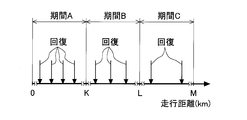
- FIG. 2 is a diagram showing the relationship between the travel distance of the vehicle on which the internal combustion engine 1 is mounted and the timing when the sulfur poisoning recovery process is performed.
- the horizontal axis is the travel distance.
- the arrow shown by “recovery” has shown the time which implements sulfur poisoning recovery processing.
- the NSR catalyst 4 is new.
- the NSR catalyst 4 When the travel distance is from 0 to K (hereinafter also referred to as period A), it is assumed that the NSR catalyst 4 has hardly deteriorated, and sulfur poisoning recovery processing is performed, for example, every 800 km travel.
- the EGR rate at this time is 15%, for example, and the NOx concentration flowing into the NSR catalyst 4 is 40 ppm, for example.
- the EGR rate is a ratio of the mass of the EGR gas to the mass of the total gas sucked into the cylinder of the internal combustion engine 1.
- the EGR rate can be changed by adjusting at least one of the opening degree of the EGR valve 22 and the opening degree of the throttle 8.
- the relationship between the opening degree of the EGR valve 22 or the opening degree of the throttle 8 and the EGR rate may be obtained in advance through experiments or the like and stored in the ECU 10. Further, the opening degree of the EGR valve 22 may be feedback controlled so that the intake air amount becomes a target value.
- the sulfur poisoning recovery process is performed every 1000 km, for example, assuming that the degradation of the NSR catalyst 4 has progressed somewhat.
- the EGR rate at this time is set to 10%, for example, and the NOx concentration flowing into the NSR catalyst 4 is set to 70 ppm, for example.
- period C when the travel distance is from L to M (hereinafter also referred to as period C), it is assumed that the deterioration of the NSR catalyst 4 has further progressed, and the sulfur poisoning recovery process is performed, for example, every 2000 km.
- the EGR rate at this time is set to 5%, for example, and the NOx concentration flowing into the NSR catalyst 4 is set to 100 ppm, for example.
- the longer the total travel distance the longer the travel distance until the sulfur poisoning recovery process is performed.
- the frequency which performs a sulfur poisoning recovery process becomes low.
- the optimum relationship between the travel distances K, L, and M in FIG. 2 and the frequency of performing the sulfur poisoning recovery process can be obtained by experiments or the like.
- the EGR rate is lowered as the mileage increases, the pump loss increases and the fuel consumption may deteriorate.
- the frequency of performing the sulfur poisoning recovery process is lowered, so that deterioration of fuel consumption can be suppressed.
- the period A, the period B, and the period C if the deterioration in fuel consumption due to the sulfur poisoning recovery process and the improvement in fuel consumption due to the supply of EGR gas are equal, in each period The deterioration in fuel consumption and the improvement are offset.
- the frequency and EGR rate of performing the sulfur poisoning recovery process are changed step by step with the period A, the period B, and the period C, but instead, according to the travel distance of the vehicle. You may change the frequency and EGR rate which perform a sulfur poisoning recovery process in a stepless manner. That is, the longer the travel distance, the lower the frequency of performing the sulfur poisoning recovery process and the lower the EGR rate.
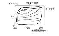
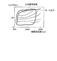
- FIG. 3 is a diagram showing an operation region in which EGR gas is supplied when the NSR catalyst 4 is new.
- FIG. 4 is a diagram showing an operation region in which EGR gas is supplied when the NSR catalyst 4 is deteriorated. 3 and 4, the horizontal axis represents the engine speed, and the vertical axis represents the shaft torque of the internal combustion engine 1. EGR gas is supplied in a region surrounded by a line indicated by “EGR use region”. The line indicated by “mode running” indicates the engine speed and torque during mode running.
- the NSR catalyst 4 when the NSR catalyst 4 is deteriorated compared to when it is new, the operation region for supplying the EGR gas is narrow. Then, when the NSR catalyst 4 is deteriorated, the amount of NOx discharged from the internal combustion engine 1 increases, so that the production of NH 3 in the NSR catalyst 4 can be promoted.
- the relationship between the engine speed and torque and the EGR rate may be set so that the EGR rate becomes lower than when the NSR catalyst 4 is new. Then, when the NSR catalyst 4 is deteriorated, the amount of NOx discharged from the internal combustion engine 1 is increased, so that the production of NH 3 in the NSR catalyst 4 can be promoted.
- the production of NH 3 may be promoted by increasing the amount of the reducing agent flowing into the NSR catalyst 4.
- NH 3 is produced by the reaction between NOx discharged from the internal combustion engine 1 and HC or H 2 as a reducing agent, and therefore, by increasing at least one of NOx or the reducing agent, The amount of NH 3 produced can be increased.
- the amount of the reducing agent can be increased by lowering the air-fuel ratio.
- the amount of NOx flowing into the NSR catalyst 4 or the amount of reducing agent can be increased by changing the ignition timing or the valve timing.
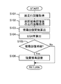
- FIG. 5 is a flowchart showing a flow of sulfur poisoning recovery processing according to the present embodiment. This routine is executed by the ECU 10 every predetermined time.
- step S101 the total travel distance of the vehicle on which the internal combustion engine 1 is mounted is acquired. This total travel distance is the distance traveled from the time when the vehicle equipped with the internal combustion engine 1 is new. This total travel distance is used as a physical quantity that is correlated with the deterioration of the NSR catalyst 4 and the SCR catalyst 5. It should be noted that other physical quantities having a correlation with the deterioration of the NSR catalyst 4 may be used. For example, the deterioration of the NSR catalyst 4 may be estimated based on the temperature history of the NSR catalyst 4. The total travel distance is stored in the ECU 10, for example. In this embodiment, the ECU 10 that processes step S101 corresponds to the detection unit in the present invention.
- step S102 the distance traveled since the previous sulfur poisoning recovery process was performed is acquired.
- This travel distance is used as a physical quantity having a correlation with the degree of sulfur poisoning of the NSR catalyst 4.
- other physical quantities correlated with the degree of sulfur poisoning of the NSR catalyst 4 may be used.
- the degree of sulfur poisoning of the NSR catalyst 4 is estimated by estimating the amount of SOx stored in the NSR catalyst 4 based on the operating state of the internal combustion engine 1 and the concentration of sulfur components in the fuel. Also good.
- step S103 an interval for performing the sulfur poisoning recovery process is calculated.
- This interval is calculated as a travel distance from when the previous sulfur poisoning recovery process is performed to when the next sulfur poisoning recovery process is performed.
- This interval is calculated based on the total travel distance acquired in step S101. The relationship between the total travel distance and the interval at which the sulfur poisoning recovery process is performed is obtained in advance through experiments or the like and stored in the ECU 10.
- step S104 the EGR rate is calculated.
- the EGR rate is calculated based on the total travel distance or the interval at which the sulfur poisoning recovery process is performed. This relationship is obtained in advance by experiments or the like and stored in the ECU 10. Then, the throttle 8 or the EGR valve 22 is controlled so that this EGR rate is obtained. As a result, an amount of NOx corresponding to the degree of deterioration of the NSR catalyst 4 is discharged from the internal combustion engine 1. That is, NOx is discharged from the internal combustion engine 1 in accordance with the required amount of NH 3 supplied to the SCR catalyst 5.
- step S104 the amount of reducing agent supplied to the NSR catalyst 4 during the reduction of NOx occluded in the NSR catalyst 4 or the generation of NH 3 to be supplied to the SCR catalyst 5 is determined as the total travel distance. You may increase according to. That is, NH 3 is produced by a reaction between NOx and a reducing agent (HC or H 2 ). For this reason, even if the EGR rate is decreased to increase the NOx emission amount or the reducing agent supply amount is increased, the amount of NH 3 produced can be increased. That is, at least one of an increase in the NOx emission amount and an increase in the supply amount of the reducing agent may be performed.
- the ECU 10 that processes step S102 and step S103 corresponds to the control unit in the present invention.
- step S105 it is determined whether or not it is time to perform the sulfur poisoning recovery process. Specifically, it is determined whether or not the travel distance calculated in step S102 reaches the interval calculated in step S103. Note that it may be determined whether or not the amount of SOx stored in the NSR catalyst 4 is equal to or greater than a threshold value. The amount of SOx may be estimated by a known technique.
- step S105 If an affirmative determination is made in step S105, the process proceeds to step S106, and the sulfur poisoning recovery process of the NSR catalyst 4 is performed. Then, when the elapsed time from the start of the sulfur poisoning recovery process of the NSR catalyst 4 is equal to or longer than the specified time, the sulfur poisoning recovery process of the NSR catalyst 4 is ended. Thereafter, NH 3 can be generated by the NSR catalyst 4 by making the air-fuel ratio rich. At this time, NH 3 is also generated by the three-way catalyst 3.
- step S105 if a negative determination is made in step S105, this routine is terminated.
- the sulfur poisoning recovery process of the NSR catalyst 4 by performing the sulfur poisoning recovery process of the NSR catalyst 4, it is possible to recover the ability to generate NH 3 , so that the reducing agent is supplied to the SCR catalyst 5. Can do. Then, as the NOx purification capacity of the NSR catalyst 4 decreases, the frequency of performing the sulfur poisoning recovery process is reduced and the amount of NOx flowing into the NSR catalyst 4 is increased so that the SCR catalyst 5 can purify NOx. Since it can promote, it can suppress that the NOx purification rate as the whole exhaust gas purification apparatus falls.
- sulfur poisoning of the NSR catalyst 4 can be properly recovered.
Landscapes
- Engineering & Computer Science (AREA)
- Chemical & Material Sciences (AREA)
- Chemical Kinetics & Catalysis (AREA)
- Combustion & Propulsion (AREA)
- Mechanical Engineering (AREA)
- General Engineering & Computer Science (AREA)
- Health & Medical Sciences (AREA)
- Toxicology (AREA)
- Exhaust Gas After Treatment (AREA)
Priority Applications (5)
| Application Number | Priority Date | Filing Date | Title |
|---|---|---|---|
| PCT/JP2011/070243 WO2013035155A1 (ja) | 2011-09-06 | 2011-09-06 | 内燃機関の排気浄化装置 |
| US14/128,176 US9297289B2 (en) | 2011-09-06 | 2011-09-06 | Exhaust gas purification apparatus for an internal combustion engine |
| JP2013532342A JP5786943B2 (ja) | 2011-09-06 | 2011-09-06 | 内燃機関の排気浄化装置 |
| CN201180071843.5A CN103620172B (zh) | 2011-09-06 | 2011-09-06 | 内燃机的排气净化装置 |
| EP11871891.5A EP2754868B1 (de) | 2011-09-06 | 2011-09-06 | Abgasreinigungsvorrichtung für einen verbrennungsmotor |
Applications Claiming Priority (1)
| Application Number | Priority Date | Filing Date | Title |
|---|---|---|---|
| PCT/JP2011/070243 WO2013035155A1 (ja) | 2011-09-06 | 2011-09-06 | 内燃機関の排気浄化装置 |
Publications (1)
| Publication Number | Publication Date |
|---|---|
| WO2013035155A1 true WO2013035155A1 (ja) | 2013-03-14 |
Family
ID=47831642
Family Applications (1)
| Application Number | Title | Priority Date | Filing Date |
|---|---|---|---|
| PCT/JP2011/070243 WO2013035155A1 (ja) | 2011-09-06 | 2011-09-06 | 内燃機関の排気浄化装置 |
Country Status (5)
| Country | Link |
|---|---|
| US (1) | US9297289B2 (de) |
| EP (1) | EP2754868B1 (de) |
| JP (1) | JP5786943B2 (de) |
| CN (1) | CN103620172B (de) |
| WO (1) | WO2013035155A1 (de) |
Cited By (2)
| Publication number | Priority date | Publication date | Assignee | Title |
|---|---|---|---|---|
| WO2015122443A1 (ja) * | 2014-02-14 | 2015-08-20 | いすゞ自動車株式会社 | 排気浄化装置及び排気浄化装置の制御方法 |
| JP6268687B1 (ja) * | 2016-10-19 | 2018-01-31 | マツダ株式会社 | エンジンの排気浄化制御装置 |
Families Citing this family (5)
| Publication number | Priority date | Publication date | Assignee | Title |
|---|---|---|---|---|
| WO2013035159A1 (ja) * | 2011-09-06 | 2013-03-14 | トヨタ自動車株式会社 | 内燃機関の排気浄化装置 |
| JP6183401B2 (ja) * | 2015-04-02 | 2017-08-23 | トヨタ自動車株式会社 | 触媒再生処理装置 |
| JP6278039B2 (ja) * | 2015-12-14 | 2018-02-14 | トヨタ自動車株式会社 | 選択還元型触媒の劣化診断装置 |
| DE102016203225A1 (de) * | 2016-02-29 | 2017-08-31 | Robert Bosch Gmbh | Verfahren zum Betreiben eines Abgasnachbehandlungssystems eines Kraftfahrzeugs |
| DE102018004892A1 (de) * | 2018-06-20 | 2019-12-24 | Daimler Ag | Verfahren zum Entschwefeln eines Stickoxid-Speicherkatalysators |
Citations (9)
| Publication number | Priority date | Publication date | Assignee | Title |
|---|---|---|---|---|
| JPH11117786A (ja) | 1997-10-17 | 1999-04-27 | Mitsubishi Motors Corp | 内燃機関の排気浄化装置 |
| JP2005105871A (ja) | 2003-09-29 | 2005-04-21 | Toyota Motor Corp | 内燃機関の触媒制御装置及び触媒劣化判定装置 |
| JP2006258047A (ja) * | 2005-03-18 | 2006-09-28 | Toyota Motor Corp | 内燃機関の排気浄化システム |
| JP2007154764A (ja) * | 2005-12-05 | 2007-06-21 | Toyota Motor Corp | 内燃機関 |
| JP2008045479A (ja) | 2006-08-15 | 2008-02-28 | Bosch Corp | 内燃機関の排気浄化装置及び排気浄化方法 |
| JP2008223611A (ja) * | 2007-03-13 | 2008-09-25 | Toyota Motor Corp | 触媒劣化判定装置 |
| JP2010116784A (ja) * | 2008-11-11 | 2010-05-27 | Mitsubishi Motors Corp | 内燃機関の排気浄化装置 |
| JP2010180792A (ja) * | 2009-02-06 | 2010-08-19 | Mitsubishi Motors Corp | 内燃機関の排気浄化装置 |
| WO2011048666A1 (ja) * | 2009-10-20 | 2011-04-28 | トヨタ自動車株式会社 | 内燃機関の排気浄化システム |
Family Cites Families (5)
| Publication number | Priority date | Publication date | Assignee | Title |
|---|---|---|---|---|
| DE10131588B8 (de) * | 2001-07-03 | 2013-11-14 | Daimler Ag | Betriebsverfahren für eine Abgasnachbehandlungseinrichtung, welche einen Stickoxid-Speicherkatalysator und stromab einen SCR-Katalysator aufweist, sowie Verwendung des SCR-Katalysators zur Entfernung von Schwefelwasserstoff |
| DE10300298A1 (de) * | 2003-01-02 | 2004-07-15 | Daimlerchrysler Ag | Abgasnachbehandlungseinrichtung und -verfahren |
| US7490464B2 (en) * | 2003-11-04 | 2009-02-17 | Basf Catalysts Llc | Emissions treatment system with NSR and SCR catalysts |
| US7213395B2 (en) * | 2004-07-14 | 2007-05-08 | Eaton Corporation | Hybrid catalyst system for exhaust emissions reduction |
| CN102089506B (zh) * | 2009-10-06 | 2013-03-20 | 丰田自动车株式会社 | 内燃机的排气净化系统 |
-
2011
- 2011-09-06 EP EP11871891.5A patent/EP2754868B1/de not_active Not-in-force
- 2011-09-06 WO PCT/JP2011/070243 patent/WO2013035155A1/ja active Application Filing
- 2011-09-06 US US14/128,176 patent/US9297289B2/en not_active Expired - Fee Related
- 2011-09-06 JP JP2013532342A patent/JP5786943B2/ja not_active Expired - Fee Related
- 2011-09-06 CN CN201180071843.5A patent/CN103620172B/zh not_active Expired - Fee Related
Patent Citations (9)
| Publication number | Priority date | Publication date | Assignee | Title |
|---|---|---|---|---|
| JPH11117786A (ja) | 1997-10-17 | 1999-04-27 | Mitsubishi Motors Corp | 内燃機関の排気浄化装置 |
| JP2005105871A (ja) | 2003-09-29 | 2005-04-21 | Toyota Motor Corp | 内燃機関の触媒制御装置及び触媒劣化判定装置 |
| JP2006258047A (ja) * | 2005-03-18 | 2006-09-28 | Toyota Motor Corp | 内燃機関の排気浄化システム |
| JP2007154764A (ja) * | 2005-12-05 | 2007-06-21 | Toyota Motor Corp | 内燃機関 |
| JP2008045479A (ja) | 2006-08-15 | 2008-02-28 | Bosch Corp | 内燃機関の排気浄化装置及び排気浄化方法 |
| JP2008223611A (ja) * | 2007-03-13 | 2008-09-25 | Toyota Motor Corp | 触媒劣化判定装置 |
| JP2010116784A (ja) * | 2008-11-11 | 2010-05-27 | Mitsubishi Motors Corp | 内燃機関の排気浄化装置 |
| JP2010180792A (ja) * | 2009-02-06 | 2010-08-19 | Mitsubishi Motors Corp | 内燃機関の排気浄化装置 |
| WO2011048666A1 (ja) * | 2009-10-20 | 2011-04-28 | トヨタ自動車株式会社 | 内燃機関の排気浄化システム |
Non-Patent Citations (1)
| Title |
|---|
| See also references of EP2754868A4 |
Cited By (3)
| Publication number | Priority date | Publication date | Assignee | Title |
|---|---|---|---|---|
| WO2015122443A1 (ja) * | 2014-02-14 | 2015-08-20 | いすゞ自動車株式会社 | 排気浄化装置及び排気浄化装置の制御方法 |
| JP2015151929A (ja) * | 2014-02-14 | 2015-08-24 | いすゞ自動車株式会社 | 排気浄化装置及び排気浄化装置の制御方法 |
| JP6268687B1 (ja) * | 2016-10-19 | 2018-01-31 | マツダ株式会社 | エンジンの排気浄化制御装置 |
Also Published As
| Publication number | Publication date |
|---|---|
| US9297289B2 (en) | 2016-03-29 |
| EP2754868A4 (de) | 2015-07-08 |
| CN103620172A (zh) | 2014-03-05 |
| CN103620172B (zh) | 2016-05-04 |
| EP2754868A1 (de) | 2014-07-16 |
| EP2754868B1 (de) | 2016-12-28 |
| US20140186220A1 (en) | 2014-07-03 |
| JPWO2013035155A1 (ja) | 2015-03-23 |
| JP5786943B2 (ja) | 2015-09-30 |
Similar Documents
| Publication | Publication Date | Title |
|---|---|---|
| US8365516B2 (en) | Exhaust gas purification apparatus for internal combustion engine | |
| JP5790868B2 (ja) | 内燃機関の排気浄化装置 | |
| JP5786943B2 (ja) | 内燃機関の排気浄化装置 | |
| US8978367B2 (en) | Exhaust gas purifying system of internal combustion engine | |
| JP5907269B2 (ja) | 内燃機関の排気浄化装置 | |
| US9528412B2 (en) | Exhaust gas purification apparatus for internal combustion engine | |
| JP6287996B2 (ja) | 内燃機関の排気浄化装置 | |
| WO2013190635A1 (ja) | 内燃機関の排気浄化装置 | |
| JP5692393B2 (ja) | 内燃機関の排気浄化装置 | |
| WO2013118252A1 (ja) | 内燃機関の排気浄化装置 | |
| JP2005048715A (ja) | 内燃機関の排気浄化装置 | |
| JP5229400B2 (ja) | 内燃機関の制御装置 | |
| US10132219B2 (en) | Emission control system and emission control method for internal combustion engine | |
| JP3838139B2 (ja) | 内燃機関の排気浄化装置 | |
| JP2008128212A (ja) | 内燃機関の排気浄化装置 | |
| US10385749B2 (en) | Exhaust gas control apparatus for internal combustion engine | |
| JP5834978B2 (ja) | 内燃機関の排気浄化装置 | |
| JP4069043B2 (ja) | 内燃機関の排気浄化装置 | |
| JP2010031737A (ja) | 空燃比制御装置及びハイブリッド車両 | |
| JP2009036153A (ja) | 内燃機関の排気浄化装置 | |
| JP4013774B2 (ja) | 内燃機関の排気浄化装置 | |
| JP2004232576A (ja) | 内燃機関の排気浄化装置 | |
| JP2015194140A (ja) | 内燃機関の制御装置 | |
| JPWO2013118252A1 (ja) | 内燃機関の排気浄化装置 |
Legal Events
| Date | Code | Title | Description |
|---|---|---|---|
| WWE | Wipo information: entry into national phase |
Ref document number: 201180071843.5 Country of ref document: CN |
|
| 121 | Ep: the epo has been informed by wipo that ep was designated in this application |
Ref document number: 11871891 Country of ref document: EP Kind code of ref document: A1 |
|
| REEP | Request for entry into the european phase |
Ref document number: 2011871891 Country of ref document: EP |
|
| WWE | Wipo information: entry into national phase |
Ref document number: 2011871891 Country of ref document: EP |
|
| ENP | Entry into the national phase |
Ref document number: 2013532342 Country of ref document: JP Kind code of ref document: A |
|
| WWE | Wipo information: entry into national phase |
Ref document number: 14128176 Country of ref document: US |
|
| NENP | Non-entry into the national phase |
Ref country code: DE |