WO2013027323A1 - Information processing apparatus, information processing system, method of processing information, and program - Google Patents
Information processing apparatus, information processing system, method of processing information, and program Download PDFInfo
- Publication number
- WO2013027323A1 WO2013027323A1 PCT/JP2012/004448 JP2012004448W WO2013027323A1 WO 2013027323 A1 WO2013027323 A1 WO 2013027323A1 JP 2012004448 W JP2012004448 W JP 2012004448W WO 2013027323 A1 WO2013027323 A1 WO 2013027323A1
- Authority
- WO
- WIPO (PCT)
- Prior art keywords
- information
- processing apparatus
- information processing
- location
- image
- Prior art date
Links
- 230000010365 information processing Effects 0.000 title claims abstract description 154
- 238000000034 method Methods 0.000 title claims abstract description 35
- 230000036961 partial effect Effects 0.000 claims abstract description 134
- 230000004044 response Effects 0.000 claims description 18
- 230000007170 pathology Effects 0.000 description 110
- 238000010586 diagram Methods 0.000 description 28
- 238000003860 storage Methods 0.000 description 27
- 238000003745 diagnosis Methods 0.000 description 20
- 238000005516 engineering process Methods 0.000 description 18
- 230000008569 process Effects 0.000 description 10
- 238000004891 communication Methods 0.000 description 7
- 238000010827 pathological analysis Methods 0.000 description 7
- 230000002829 reductive effect Effects 0.000 description 6
- 230000003287 optical effect Effects 0.000 description 5
- 239000003086 colorant Substances 0.000 description 3
- 239000011521 glass Substances 0.000 description 3
- 238000004519 manufacturing process Methods 0.000 description 3
- 230000006835 compression Effects 0.000 description 2
- 238000007906 compression Methods 0.000 description 2
- 238000005520 cutting process Methods 0.000 description 2
- 238000005401 electroluminescence Methods 0.000 description 2
- 230000008094 contradictory effect Effects 0.000 description 1
- 239000006059 cover glass Substances 0.000 description 1
- 230000003247 decreasing effect Effects 0.000 description 1
- 239000000284 extract Substances 0.000 description 1
- 230000006870 function Effects 0.000 description 1
- 238000007689 inspection Methods 0.000 description 1
- 239000004973 liquid crystal related substance Substances 0.000 description 1
- PWPJGUXAGUPAHP-UHFFFAOYSA-N lufenuron Chemical compound C1=C(Cl)C(OC(F)(F)C(C(F)(F)F)F)=CC(Cl)=C1NC(=O)NC(=O)C1=C(F)C=CC=C1F PWPJGUXAGUPAHP-UHFFFAOYSA-N 0.000 description 1
- 238000012986 modification Methods 0.000 description 1
- 230000004048 modification Effects 0.000 description 1
- 238000002360 preparation method Methods 0.000 description 1
- 230000009467 reduction Effects 0.000 description 1
- 230000000717 retained effect Effects 0.000 description 1
- 238000004904 shortening Methods 0.000 description 1
- 239000007787 solid Substances 0.000 description 1
- 238000001356 surgical procedure Methods 0.000 description 1
- 210000001835 viscera Anatomy 0.000 description 1
Images


Classifications
-
- G—PHYSICS
- G16—INFORMATION AND COMMUNICATION TECHNOLOGY [ICT] SPECIALLY ADAPTED FOR SPECIFIC APPLICATION FIELDS
- G16H—HEALTHCARE INFORMATICS, i.e. INFORMATION AND COMMUNICATION TECHNOLOGY [ICT] SPECIALLY ADAPTED FOR THE HANDLING OR PROCESSING OF MEDICAL OR HEALTHCARE DATA
- G16H30/00—ICT specially adapted for the handling or processing of medical images
- G16H30/40—ICT specially adapted for the handling or processing of medical images for processing medical images, e.g. editing
-
- H—ELECTRICITY
- H04—ELECTRIC COMMUNICATION TECHNIQUE
- H04N—PICTORIAL COMMUNICATION, e.g. TELEVISION
- H04N5/00—Details of television systems
- H04N5/222—Studio circuitry; Studio devices; Studio equipment
- H04N5/262—Studio circuits, e.g. for mixing, switching-over, change of character of image, other special effects ; Cameras specially adapted for the electronic generation of special effects
- H04N5/265—Mixing
-
- G—PHYSICS
- G16—INFORMATION AND COMMUNICATION TECHNOLOGY [ICT] SPECIALLY ADAPTED FOR SPECIFIC APPLICATION FIELDS
- G16H—HEALTHCARE INFORMATICS, i.e. INFORMATION AND COMMUNICATION TECHNOLOGY [ICT] SPECIALLY ADAPTED FOR THE HANDLING OR PROCESSING OF MEDICAL OR HEALTHCARE DATA
- G16H80/00—ICT specially adapted for facilitating communication between medical practitioners or patients, e.g. for collaborative diagnosis, therapy or health monitoring
-
- H—ELECTRICITY
- H04—ELECTRIC COMMUNICATION TECHNIQUE
- H04L—TRANSMISSION OF DIGITAL INFORMATION, e.g. TELEGRAPHIC COMMUNICATION
- H04L12/00—Data switching networks
- H04L12/02—Details
- H04L12/16—Arrangements for providing special services to substations
- H04L12/18—Arrangements for providing special services to substations for broadcast or conference, e.g. multicast
- H04L12/1813—Arrangements for providing special services to substations for broadcast or conference, e.g. multicast for computer conferences, e.g. chat rooms
- H04L12/1827—Network arrangements for conference optimisation or adaptation
-
- H—ELECTRICITY
- H04—ELECTRIC COMMUNICATION TECHNIQUE
- H04M—TELEPHONIC COMMUNICATION
- H04M3/00—Automatic or semi-automatic exchanges
- H04M3/42—Systems providing special services or facilities to subscribers
- H04M3/56—Arrangements for connecting several subscribers to a common circuit, i.e. affording conference facilities
- H04M3/567—Multimedia conference systems
-
- H—ELECTRICITY
- H04—ELECTRIC COMMUNICATION TECHNIQUE
- H04N—PICTORIAL COMMUNICATION, e.g. TELEVISION
- H04N7/00—Television systems
- H04N7/14—Systems for two-way working
- H04N7/15—Conference systems
Definitions
- the present technology relates to an information processing apparatus which may have a pathology image in common with another information processing apparatus to make a user observe the image, an information processing system having the information processing apparatus, a method of processing information in the information processing apparatus, and a program for the information processing apparatus.
- Patent Literature (PTL) 1 an information communication service system, in which a conference is expedited while each of user terminals takes out contents registered in advance if necessary, is disclosed.
- a server receives videos and voices transmitted from a plurality of terminals in real time, synthesizes these ones, and delivers the synthesized ones to the terminals.
- PTL 4 described later discloses that a reproduction apparatus downloads in advance contents, of which the date and time to be provided for viewers is predetermined, from a server in a ciphered state, receives a key from the server at a viewable date and time, and deciphers the contents with the key to reproduce the contents.
- terminals of a plurality of users e.g., doctors
- have an image for pathological diagnosis in common with one another and hold a teleconference to make a diagnosis while transmitting opinions among user's terminals. Therefore, the diagnosis is efficiently made.
- a server and client system delivers a plurality of tile images composing a pathology image to clients, and each client synthesizes the pathology image from the tile images and views the pathology image.
- the load on the server is decreased with the reduction of data communication performed during the conference.
- the communication using the pathology image data is performed, it is very time-consuming to download the data in advance.
- efficiency in the download in advance is very low in view of effective use of a network band.
- An information processing apparatus includes a processor, a display device, and a memory device storing instructions. When executed by the processor, the instructions cause the processor to: (a) in response to an operation input, determine area specifying information and location information, the area specifying information specifying a display area in an image, the display area including a plurality of partial images, the location information indicating at least one location of the plurality of partial images, (b) transmit the area specifying information and the location information to a first information processing apparatus, the first information processing apparatus being configured to, in response to receiving the area specifying information and the location information, transmit the area specifying information and the location information to a second information processing apparatus, (c) transmit a request for the plurality of partial images to the at least one location indicated by the location information, (d) receive the plurality of partial images from the at least one location, and (e) display the received plurality of partial images.
- the information processing apparatus may receive each of the partial images of the pathology image from an arbitrary location being the same or different from locations of the other partial images, as compared with the case where the locations are concentrated into one point, the time required to prepare a teleconference using the pathology image with another information processing apparatus may be shortened. Further, because the information processing apparatus is not required to determine the display area in the pathology image, the teleconference using the pathology image may be expedited efficiently and smoothly by receiving the partial image according to the area specifying information and by displaying the partial image.
- the information processing apparatus may further have storage.
- the processor may be configured to determine whether or not the partial images included in the display area are stored in the storage, and to be capable of controlling the display, when the partial images are stored in the storage, to display the partial images without transmitting the request information to the location.
- the information processing apparatus access the location. Accordingly, the traffic on the network may be reduced, and the teleconference using the pathology image may be further efficiently expedited.
- the processor may be configured to be capable of controlling the information processing apparatus to receive, in advance, image specifying information, temporary location information, and diagnosis record information from the other information processing apparatus before receiving the area specifying information and the location information, the image specifying information specifying a pathology image that is capable of being used in a teleconference held with the other information processing apparatus, the temporary location information indicating a location of the specified pathology image at this time, the diagnosis record information indicating a past diagnosis record of the specified pathology image, and to receive a partial image, associated with the received diagnosis record information, among a plurality of partial images composing the pathology image specified by the received image specifying information, from the location indicated by the temporary location information.
- the processor may be configured to be capable of controlling the storage to store the received partial image.
- the information processing apparatus may download in advance a specific partial image, which may be used in the teleconference at a high probability, to store the specific partial image in the storage. Accordingly, the traffic during the teleconference may be reduced, and the teleconference using the pathology image may be efficiently expedited.
- the processor may be configured to be capable of controlling the information processing apparatus to receive display record information, indicating one of a past display area and a display position in the specified pathology image, as the diagnosis record information. Therefore, the information processing apparatus may further efficiently expedite the teleconference using the pathology image by downloading in advance a partial image which may be displayed in the teleconference at a high probability in the same manner as in the past.
- the processor may be configured to be capable of controlling the information processing apparatus to receive annotation information, affixed to a predetermined position in the specified pathology image, as the diagnosis record information.
- the information processing apparatus may further efficiently expedite the teleconference by downloading in advance the partial image to which annotation information is affixed and which may attract attention in the teleconference at a high probability in the same manner as in the past.
- the pathology image may exist for each of a plurality of slices, which are taken out from one biological tissue and are stained with different colors, respectively, to form a plurality of pathology images.
- the processor may be configured to be capable of controlling the information processing apparatus to receive a partial image existing at a predetermined position, to which the annotation information is affixed, in a first pathology image of a slice stained with a first color, and to receive a partial image existing at the position same as the predetermined position in a second pathology image of a slice stained with a second color.
- the information processing apparatus may download in advance not only the partial image of the first pathology image, to which the annotation information is affixed, but also the partial image of the second pathology image which is taken from the biological tissue in common with the first pathology image but is of a slice stained in a color differing from that in the first pathology image.
- Images of a slice taken out from one biological tissue may be taken at a plurality of different resolutions, and the pathology image may exist for each of the plurality of resolutions to form a plurality of pathology images.
- the processor may be configured to be capable of controlling the information processing apparatus to receive a partial image existing at a predetermined position, to which the annotation information is affixed, in a first pathology image taken at a first resolution, and to receive a partial image existing at the position same as the predetermined position in a second pathology image taken at a second resolution.
- the information processing apparatus may download in advance not only the partial image of the first pathology image, to which the annotation information is affixed, but also the partial image of the second pathology image which is taken from the biological tissue in common with the first pathology image but of which the resolution differs from the resolution of the first pathology image.
- the processor may be configured to be capable of controlling the information processing apparatus to receive the area specifying information from the other information processing apparatus via a first server apparatus.
- the location may indicate a second server apparatus different from the first server apparatus.
- the pathology image and the area specifying information are managed in different servers, respectively. Accordingly, it may be prevented that the concentration of the load on a specific server disturbs the expedition of the teleconference.
- An information processing apparatus includes a processor, and a memory device storing instructions. When executed by the processor, the instructions cause the processor to: (a) receive, from a first information processing apparatus, area specifying information and location information, the area specifying information specifying a display area in an image, the display area including a plurality of partial images, the location information indicating at least one location of the plurality of partial images; and (b) transmit, to a second information processing apparatus, the area specifying information and the location information.
- an information processing apparatus comprising: a processor, a display device, and a memory device storing instructions.
- the instructions When executed by the processor, the instructions cause the processor to: (a) receive area specifying information and location information from a first information processing apparatus, the area specifying information specifying a display area in an image, the display area including a plurality of partial images, the location information indicating at least one location of the plurality of partial images, (b) transmit a request for the plurality of partial images to the at least one location indicated by the location information, (c) receive the plurality of partial images from the at least one location, and (d) display the received plurality of partial images.
- a method of operating an information processing apparatus includes (a) causing a processor to execute instructions to receive, from a first information processing apparatus, area specifying information and location information, the area specifying information specifying a display area in an image, the display area including a plurality of partial images, the location information indicating at least one location of the plurality of partial images, and (b) causing the processor to execute instructions to transmit, to a second information processing apparatus, the area specifying information and the location information.
- a system including a first, second, and third information processing apparatus.
- the first information processing apparatus is configured to, in response to an operation input, determine area specifying information and location information, the area specifying information specifying a display area in an image, the display area including a plurality of partial images, the location information indicating at least one location of the plurality of partial images.
- the second information processing apparatus is configured to receive the area specifying information and the location information from the first information processing apparatus.
- the third information processing apparatus is configured to: (a) receive the area specifying information and the location information from the second information processing apparatus, (b) transmit a request for the plurality of partial images to the at least one location indicated by the location information, (c) receive the plurality of partial images from the at least one location; and (d) display the received plurality of partial images.
- the time required to prepare the holding of a teleconference in which data of the pathology image are possessed in common may be shortened, and the teleconference may be expedited efficiently and smoothly.
- Fig. 1 is a block diagram showing the configuration of a teleconference system according to a first embodiment of the present technology.
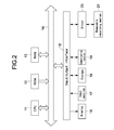
- Fig. 2 is a block diagram showing the configuration of hardware of a PC in the system.
- Fig. 3 is a diagram explaining a display principle of a pathology image treated in the system.
- Fig. 4 is a diagram indicating the procedure in the case of producing an image group of the pathology image treated in the system.
- Fig. 5 is a flowchart showing the processing in a PC being the chairman when a pathology image is displayed in the system.
- Fig. 6 is a flowchart showing the processing in a PC being an audience when a pathology image is displayed in the system.
- Fig. 1 is a block diagram showing the configuration of a teleconference system according to a first embodiment of the present technology.
- Fig. 2 is a block diagram showing the configuration of hardware of a PC in the system.
- Fig. 3 is a diagram explaining a display principle of a
- FIG. 7 is a block diagram showing the configuration of a teleconference system according to a second embodiment of the present technology.
- Fig. 8 is a diagram showing the specification of tiles, to be downloaded in advance, on the basis of past operation record information in the system according to the second embodiment.
- Fig. 9 is a diagram showing the specification of tiles, to be downloaded in advance, on the basis of past operation record information in the system according to the second embodiment.
- Fig. 10 is a diagram showing the specification of tiles, to be downloaded in advance, on the basis of past operation record information in the system according to the second embodiment.
- Fig. 11 is a diagram showing the specification of a tile, to be downloaded in advance, according to past annotation information in the system according to the second embodiment.
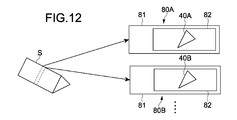
- FIG. 12 is a diagram showing the production of a pathology slide from a plurality of slices of a biological tissue.
- Fig. 13 is a flowchart showing one example of the processing in a PC and a server when a pathology image is downloaded in advance in the system according to the second embodiment.
- Fig. 14 is a flowchart showing another example of the processing in a PC and a server when a pathology image is downloaded in advance in the system according to the second embodiment.
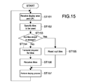
- Fig. 15 is a flowchart showing the processing in a PC being an audience when a pathology image is displayed in the system.
- Fig. 16 is a block diagram showing the configuration of a teleconference system according to a third embodiment. Fig.
- FIG. 17 is a block diagram showing the configuration of a teleconference system according to a fourth embodiment.
- Fig. 18 is a block diagram showing the configuration of a teleconference system according to a fifth embodiment.
- Fig. 19 is a flowchart showing the processing in a PC according to the fifth embodiment.
- Fig. 20 is a block diagram showing the configuration of a teleconference system according to a sixth embodiment.
- Fig. 21 is a block diagram showing the configuration of a teleconference system according to a seventh embodiment.
- Fig. 1 is a block diagram showing the configuration of a teleconference system using a pathology image according to the first embodiment.
- a diagnosis is efficiently made by holding a teleconference, while personal computers (PCs) of a plurality of users (e.g., doctors) have an image for pathological diagnosis (a pathology image) in common with one another, and by making a diagnosis while opinions are transmitted among the PCs.
- PCs personal computers
- a pathological diagnosis a pathology image
- this system has a server 200, a plurality of PCs 100, and a scanner 300. These may communicate with one another via the Internet 150.
- Data of a pathology image taken by the scanner 300 are uploaded to the server 200 via the Internet 150 and are stored.
- the pathology image is obtained by taking an image of a slice of a biological tissue or the like held in a glass slide.
- the pathology image data are not stored only in the server 200, but may be stored in any of the PCs 100.
- one of the plurality of PCs 100 acts as the "chairman" of the teleconference, and the other ones act as "audiences".
- a pathology image specified by the PC 100 as the chairman is displayed on the PCs 100 as audiences.
- the PC 100 acting as the chairman transmits information (area specifying information), specifying a display area in the pathology image for a diagnosis in the teleconference, and information (URL; uniform resource locator), indicating locations of the pathology image data, to the server 200.
- the server 200 transmits the area specifying information and the URL to the PCs 100 acting as the audiences. That is, the PC 100 acting as the chairman transmits the area specifying information and the URL to the PCs 100 acting as the audiences via the server 200.
- Each PC 100 acting as the audience receives an image (a partial image) of the pathology image existing in the area, specified by the area specifying information, from the URL and displays the partial image. Therefore, the PCs 100 have the pathology image in common with one another, and a pathological diagnosis may be made by the users of the PCs 100.
- Fig. 2 is a block diagram showing the hardware configuration of one PC 100.
- Each PC 100 has a central processing unit (CPU) 11, a read only memory (ROM) 12, a random access memory (RAM) 13, an input/output interface 15, and a bus 14 connecting these ones with one another.
- CPU central processing unit
- ROM read only memory
- RAM random access memory
- bus 14 connecting these ones with one another.
- the input/output interface 15 is connected with a display 16, an input section 17, storage 18, a communicating section 19, a driver 20, and the like.
- the display 16 is, for example, a display device using liquid crystal, electro-luminescence (EL) or the like.
- the input section 17 is, for example, a pointing device, a keyboard, a touch panel, a microphone, or another operating device.
- the touch panel may be integrally formed with the display 16.
- the storage 18 is a nonvolatile storage device, for example, being a hard disk drive (HDD), a flash memory, or another solid memory.
- HDD hard disk drive
- flash memory or another solid memory.
- an application program to be executed to receive and display the pathology image data in this system, is stored.
- the driver 20 is, for example, a device capable of driving a removable recording medium 21 such as an optical recording medium, a floppy (registered trademark) disk, a magnetic recording tape, or a flash memory.
- the storage 18 is often used as a device which is mounted in the PC 100 in advance and drives a non-removable recording medium.
- the communicating section 19 is a modem, a router, or another communicating device which communicates with another device and may be connected to a local area network (LAN), a wide area network (WAN), or the like.
- the communicating section 19 may use any of wire communication and wireless communication.
- the communicating section 19 is often used while being formed independent of the PC 100.
- the hardware configuration of the server 200 is also the same as the hardware configuration of the PC 100 and has blocks such as a control section, storage, and a communicating section being necessary to act as a computer.
- Fig. 3 is a diagram showing an image pyramid structure for explaining the display principle.
- An image pyramid structure 50 is an image group (a total image group) of which images are produced from a single pathology image, obtained from a single observation object 40 (see Fig. 4) by an optical microscope, at a plurality of different resolutions respectively.
- the image having the largest size is located in the lowest layer of the image pyramid structure 50, while the image having the smallest size is located in the highest layer.
- the resolution of the largest sized image is, for example, 50 x 50 kilopixels or 30 x 40 kilopixels.
- the resolution of the smallest sized images is, for example, 256 x 256 pixels or 256 x 512 pixels.
- the same display 16 displays these images, for example, in 100% size (each of the images is displayed at the number of physical dots which is the same as the number of pixels in the image), the image having the largest size is displayed in the largest size, and the image having the smallest size is displayed in the smallest size.
- the display area of the display 16 is indicated by D.
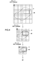
- Fig. 4 is a diagram for explaining the procedure in the case of producing the image group of the image pyramid structure 50.
- a digital image of an original image (a huge image) obtained at a predetermined observation magnification by an optical microscope (not shown) is prepared.
- This original image is equivalent to the largest sized image being the lowest image of the image pyramid structure 50 shown in Fig. 3, and is an image having the highest resolution. Therefore, as the lowest image of the image pyramid structure 50, an image obtained by observing at a comparatively high resolution by the optical microscope is used.
- a slice thinly cut off from a living internal organ, a biological tissue, a cell, or a part of any one of these is an observation object 40. Then, the observation object 40 held in a glass slide is read out by the scanner 300 having the function of an optical microscope, and an obtained digital image is stored in the scanner 300 or other storage.
- this scanner 300 or a generally-used computer produces a plurality of images which respectively have resolutions lowered step by step from the largest sized image obtained as described above, and stores these images, for example, every "tile" (partial image) unit denoting a unit of a predetermined size.
- the size of one tile is, for example, 256 x 256 pixels.
- identification information an ID or a number identifying the tile is added.
- the image group produced as described above forms the image pyramid structure 50, and this image pyramid structure 50 is stored in the storage 18 of the PC 100 or storage of the server 200.
- the PC 100 or the server 200 may store the images having a plurality of different resolutions and pieces of information of the resolutions while the images are associated with the pieces of information respectively.
- the PC 100 may perform the production and storage of the image pyramid structure 50.
- the total image group forming this image pyramid structure 50 may be produced by a known compression method, and may be, for example, produced by a known compression method for producing a thumbnail image.
- the PC 100 When the user of each PC 100 views the pathology image stored in the storage 18 of the PC 100 not in a teleconference but in stand-alone, the PC 100 extracts a desired image from the image pyramid structure 50 in response to the operation of the user input from the input section 17 and displays this image on the display 16. In this case, the PC 100 displays an image of an arbitrary portion, selected by the user, from among images having an arbitrary resolution selected by the user. While the user changes the observation magnification, the user may obtain a feeling that the user actually observes the observation object 40. That is, in this case, the PC 100 acts as a virtual microscope, and a virtual observation magnification is practically equivalent to the resolution described above.
- Fig. 5 is a flowchart showing the processing in the PC 100 being the chairman when a pathology image is displayed according to this embodiment
- Fig. 6 is a flowchart showing the processing in the PC 100 being one audience in this case.
- the CPU 11 of the PC 100 being the chairman waits for an operation input of the user which specifies a display area in a specific pathology image (step 51) and specifies the display area when receiving this operation input (step 52).
- the CPU 11 specifies tiles of the pathology image used for the display process, that is, tiles (partial images) of which all or a part is included in the display area (step 53).
- the CPU 11 transmits a request for data of the specified tiles to the server 200 (step 54).
- the CPU 11 transmits display area information indicating the display area and a URL of the specified tile data to the server 200 (step 55).
- the CPU 11 receives the tile data transmitted from the server 200 in response to the request (step 56) and displays the tile data on the display (step 57).
- the CPU 11 of the PC 100 being each audience receives the display area information and the URL transmitted from the PC 100 being the chairman via the server 200 (step 61).
- the CPU 11 specifies tiles of the pathology image required for the display process of the display area on the basis of the display area information (step 62).
- the CPU 11 transmits the request for the specified tiles to the server 200 on the basis of the received URL (step 63).
- the CPU 11 receives tiles transmitted in response to the request (step 64), and displays the tiles on the display 16 (step 65).
- Fig. 7 is a block diagram showing the configuration of a teleconference system according to this embodiment.
- the pathology image is stored in the server 200, and is downloaded to the PC 100 on the day on which the teleconference is held.
- the PC 100 may also download the pathology image to the storage 18 before the conference is held. This downloading may be performed in a tile unit without being performed in a unit of the whole pathology image.
- each tile being used in the teleconference at a high probability may be downloaded.
- the tiles being used at a high probability are, for example, the tiles used for a pathological diagnosis in the past.
- the tiles used for a past pathological diagnosis are, for example, specified according to a following criterion.
- the PC 100 specifies tiles used for a past diagnosis on the basis of a display operation record indicating that at which magnification (resolution) a doctor making a diagnosis in the past viewed a pathology image and how the doctor moved coordinates or a display area.
- Fig. 8, Fig. 9, and Fig. 10 are diagrams showing examples of tiles specified on the basis of this operation record information.
- each tile 70 of which all or a part is included in this rectangle is specified.
- the PC 100 specifies a tile to which this annotation is affixed.
- the annotation denotes information which is, for example, formed in a style of a symbol, a diagram, a text, a voice, an image, a link (e.g., URL), or the like on the basis of user's input on the PC displaying the pathology image.
- a tile 70, to which an annotation 73 indicated by a symbol X is affixed, among tiles composing the pathology image I is specified.
- the annotation indicated by a line, a rectangle, or a circle is affixed, in the same manner as in Fig. 8 to Fig. 10, tiles on which the line goes across or tiles included in the rectangle or the circle are specified.
- Fig. 12 is a diagram showing the preparation of slides (pathology slides) in which slices are held to be photographed for pathology images.
- a pathology slide 80 is prepared by cutting off the observation object (a slice) 40 at the thickness of two to three micrometers from a pathology piece (a biological tissue) S taking out by a surgery or the like, mounting the slice 40 on a slide glass 81, and covering the slice 40 with a cover glass 82.
- slices successively cutting off have approximately the same tissue shape and the same medical feature of cell and the like. That is, as shown in this figure, diagnosis information affixed to a pathology slide 80A of a slice 40A is also useful for an adjacent pathology slide 80B of a slice 40B.
- the different slices 40A and 40B are stained with different colors to perform different inspections respectively. Accordingly, when a plurality of pathology images relating to the successive slices stained with different colors exist, the PC 100 specifies a tile of one pathology image to which an annotation is affixed, and specifies a tile of another pathology image existing at the same coordinates as those of the position at which the annotation is affixed.
- the user may see one pathology image while changing the observation magnification (the resolution). Accordingly, when an annotation is affixed to a certain pathology image, this annotation is also useful information for another pathology image of the same observation object of which the magnification (the resolution) differs from that of the certain pathology image. Accordingly, when an annotation is affixed to a certain pathology image, the PC 100 specifies a tile of the certain pathology image to which the annotation is affixed, and also specifies a tile, which includes the same coordinates as coordinates at which the annotation is affixed, in another pathology image of the same observation object having a different resolution.
- Fig. 13 is a flowchart showing the processing in the PC 100 and the server 200 in the download of a pathology image in advance.
- pathology image data to be used for a teleconference and a list of participants of the teleconference are transmitted from the PC 100 of the promoter of the teleconference to the server 200 and are registered (step 131).
- This process is, for example, performed by selecting a desired pathology image and users from data of all pathology images and a list of all users existing in the server 200.
- the server 200 transmits a notice of a conference holding to the PC 100 of each participant (step 132).
- the PC 100 of each participant determines whether or not the storage 18 such as a HDD having a capacity capable of downloading a pathology image in advance exists in the PC 100 (step S133).
- the PC 100 of the participant receives a list of pathology image data to be used in the teleconference from the server 200 (step 134). In this case, past diagnosis record information relating to these pathology image data and the URL of the pathology image data (tiles) at this time are also received.
- the PC 100 specifies tiles according to the criterion described above on the basis of the received list of pathology image data and the received diagnosis record information, and downloads the specified tiles from the server 200 (step 135).
- the PC 100 of the participant may participate in the conference by being connected to the server 200 (step 136).
- the list of data to be used in the conference is determined.
- the list is updated by deleting unnecessary data by the promoter, or by adding, by another participant, data that this participant wishes to use.
- step 141 to step 145 after the PC 100 performs the same processes as those at step 131 to step 135 of Fig. 13, the PC 100 determines whether or not the start time of the teleconference comes (step 146).
- the PC 100 accesses the server 200 and determines whether or not the list of pathology image data to be used has been updated (step 147).
- the PC 100 receives a new list from the server 200 and repeats the processes performed at step 144 and steps following step 144.
- the PC 100 may receive a new list in response to a notice that indicates the update of the list and is sent from the server 200 to the PC 100 of each participant.
- the destination to which tiles are downloaded in advance is not limited to the storage 18 of the PC 100.
- the downloading to a neighboring storage device connected with the PC 100 via a network is possible.
- the downloading to the server 200 closest to the PC 100 is allowed.
- Fig. 15 is a flowchart showing the processing in the PC 100 being an audience when a pathology image is displayed in the system according to this embodiment.
- the CPU 11 of the PC 100 determines whether or not specified tiles are stored in the storage 18 (whether or not specified tiles have been downloaded in advance) (step 153).
- the CPU 11 transmits a request for the tiles to the server 200 (step 154), and receives the tiles (step 156).
- the CPU 11 reads out the tiles from the storage 18 (step 155).
- the CPU 11 displays the tiles, received or read out, on the display 16 (step 157).
- Fig. 16 is a block diagram showing the configuration of a teleconference system according to this embodiment.
- both the display area information and the tile data of the pathology image are stored in the server 200.
- a tile data server 200A for storing the tile data and a control data server 200B for processing the display area information are separately located.
- the control data server 200B the past diagnosis record information described in the second embodiment, the list of tile data, the list of participants, and the like are managed (hereinafter, these data are called control data in a lump).
- the server is optimized for control data which has a small data capacity but needs a rapid response, and tile data which has a large data capacity and needs a high throughput.
- control data may be exchanged in the P2P communication among a plurality of PC 100.
- Fig. 17 is a block diagram showing the configuration of a teleconference system according to this embodiment.
- a teleconference is held among a plurality of hospitals by connecting in-hospital networks 170 with one another.
- pathology image data to be used in the conference are gathered to a single point, the cost for uploading and downloading is increased.
- pathology image data to be used in the teleconference are originally obtained by taking an image by a scanner 300 of each hospital and are retained in the in-hospital servers 200A. Therefore, as shown in this figure, in this embodiment, the in-hospital server 200A of each hospital is used in place of the tile data server 200A in the third embodiment. In this case, the control data server 200B also exists on the Internet 150.
- Fig. 18 is a block diagram showing the configuration of a teleconference system according to this embodiment.
- the in-hospital server delivers the tile data to participants of a teleconference. Therefore, there is a probability that a problem occurs in view of the load on the server depending on the network bandwidth and the number of the PCs 100.
- tile data to be downloaded are uploaded to a cloud server 200C in advance. Accordingly, the load on the in-hospital server 200D is reduced.
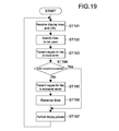
- Fig. 19 is a flowchart showing the display process in the PC 100 according to this embodiment.
- the CPU 11 of the PC 100 transmits a request for the specified tiles to the cloud server 200C (step 193).
- the CPU 11 determines whether or not the tiles to be requested are successfully received (step 194).
- the CPU 11 When failing in the reception of the tiles (NO), the CPU 11 transmits a request for the tiles to the in-hospital server 200D (step 196), and receives the tiles (step 197). Thereafter, the received tiles are displayed (step 197).
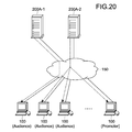
- Fig. 20 is a block diagram showing the configuration of a teleconference system according to this embodiment.
- tile server 200A-1 and 200A-2 a plurality of tile servers for delivering the same tile data are located (tile servers 200A-1 and 200A-2).
- the tile server 200A-1 is set as a primary server
- the tile server 200A-2 is set as a secondary server.
- a server optimum to one PC 100 being a client is determined for each PC 100, the system may cope with the increase in the number of PCs 100.
- each of the following server determining algorithms may be used.
- a server is statistically allocated to one client in advance for each client.
- the client selects the server having the smallest RTT (Round Trip Time).
- the client selects the server having the widest bandwidth.
- the primary server determines while considering the total load.
- the roundrobin processing is performed.
- the load information of the server is periodically (e.g., every 10 seconds) obtained.
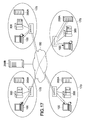
- Fig. 21 is a block diagram showing the configuration of a teleconference system according to this embodiment.
- tile data for which a diagnosis was finished is retreated from the in-hospital network 170 to the cloud server 200C via the Internet 150.
- the tile data retreated to the cloud server 200C is returned to the in-hospital server 200D at the time of the reservation.
- the configurations of the first to seventh embodiments may be combined with one another in any manner if the combined embodiments are not contradictory to one another.
- the download process in advance in the second embodiment may be embodied in the configuration that the server is separately divided into the tile data server and the control data server as described in the third embodiment.
- an information processing apparatus includes a processor and a memory device storing instructions. When executed by the processor, the instructions cause the processor to:(a) receive, from a first information processing apparatus, area specifying information and location information, the area specifying information specifying a display area in an image, the display area including a plurality of partial images, the location information indicating at least one location of the plurality of partial images; and(b) transmit, to a second information processing apparatus, the area specifying information and the location information.
- the image includes data representative of a slice of a biological tissue.
- the information processing apparatus includes a server
- the first information processing apparatus includes a first personal computer
- the second information processing apparatus includes a second personal computer
- the plurality of partial images includes (a) a first partial image stored at a first location, and (b) a second partial image stored at a second location.
- the area specifying information is determined based on a display record.
- the area specifying information is determined based on annotation information.
- an information processing apparatus includes a processor, a display device, and a memory device storing instructions. When executed by the processor, the instructions cause the processor to: (a) in response to an operation input, determine area specifying information and location information, the area specifying information specifying a display area in an image, the display area including a plurality of partial images, the location information indicating at least one location of the plurality of partial images, (b) transmit the area specifying information and the location information to a first information processing apparatus, the first information processing apparatus being configured to, in response to receiving the area specifying information and the location information, transmit the area specifying information and the location information to a second information processing apparatus, (c) transmit a request for the plurality of partial images to the at least one location indicated by the location information, (d) receive the plurality of partial images from the at least one location; and (e) display the received plurality of partial images.
- the image includes data representative of a slice of a biological tissue.
- the information processing apparatus includes a first personal computer, (b) the first information processing apparatus includes a server; and (c) the second information processing apparatus includes a second personal computer.
- the plurality of partial images includes: (a) a first partial image stored at a first location, and (b) a second partial image stored at a second location.
- the instructions when executed by the processor, cause the processor to: (a) receive the first partial image from the first location, and (b) receive the second partial image from the second location.
- the instructions when executed by the processor, cause the processor to: (a) determine whether the first partial image is stored by the memory device, (b) in response to a determination that the first partial image is stored by the memory device, read out the first partial image from the memory device, and (c) for the first partial image, do not transmit a request to the at least one location indicated by the location information.
- the instructions when executed by the processor, cause the processor to determine the area specifying information based on a display record.
- the instructions when executed by the processor, cause the processor to determine the area specifying information based on annotation information.
- an information processing apparatus includes a processor, a display device, and a memory device storing instructions. When executed by the processor, the instructions cause the processor to: (a) receive area specifying information and location information from a first information processing apparatus, the area specifying information specifying a display area in an image, the display area including a plurality of partial images, the location information indicating at least one location of the plurality of partial images, (b) transmit a request for the plurality of partial images to the at least one location indicated by the location information, (c) receive the plurality of partial images from the at least one location, and (d) display the received plurality of partial images.
- the image includes data representative of a slice of a biological tissue.
- the information processing apparatus includes a personal computer, and (b) the first information processing apparatus includes a server.
- the plurality of partial images includes: (a) a first partial image stored at a first location, and (b) a second partial image stored at a second location.
- the instructions when executed by the processor, cause the processor to: (a) receive the first partial image from the first location, and (b) receive the second partial image from the second location.
- the instructions when executed by the processor, cause the processor to: (a) determine whether the first partial image is stored by the memory device, (b) in response to a determination that the first partial image is stored by the memory device, read out the first partial image from the memory device, and (c) for the first partial image, do not transmit a request to the at least one location indicated by the location information.
- the area specifying information is determined based on a display record.
- the area specifying information is determined based on annotation information.
- a method of operating an information processing apparatus includes (a) causing a processor to execute instructions to receive, from a first information processing apparatus, area specifying information and location information, the area specifying information specifying a display area in an image, the display area including a plurality of partial images, the location information indicating at least one location of the plurality of partial images, and (b) causing the processor to execute instructions to transmit, to a second information processing apparatus, the area specifying information and the location information.
- the image includes data representative of a slice of a biological tissue.
- the information processing apparatus includes a server
- the first information processing apparatus includes a first personal computer
- the second information processing apparatus includes a second personal computer
- the plurality of partial images includes: (a) a first partial image stored at a first location, and (b) a second partial image stored at a second location.
- the area specifying information is determined based on a display record.
- the area specifying information is determined based on annotation information.
- a system in another embodiment, includes first, second, and third information processing apparatus.
- the first information processing apparatus is configured to, in response to an operation input, determine area specifying information and location information, the area specifying information specifying a display area in an image, the display area including a plurality of partial images, the location information indicating at least one location of the plurality of partial images.
- the second information processing apparatus is configured to receive the area specifying information and the location information from the first information processing apparatus.
- the third information processing apparatus is configured to: (a) receive the area specifying information and the location information from the second information processing apparatus, (b) transmit a request for the plurality of partial images to the at least one location indicated by the location information, (c) receive the plurality of partial images from the at least one location, and (d) display the received plurality of partial images.
- CPU 16 display 18 storage 19 communicating section 40 observation object 70 tile 71 coordinates moving path 72 display area 73 annotation 100 PC 150 Internet 170 in-hospital network 200 server 300 scanner
Landscapes
- Engineering & Computer Science (AREA)
- Multimedia (AREA)
- Signal Processing (AREA)
- Health & Medical Sciences (AREA)
- Medical Informatics (AREA)
- General Health & Medical Sciences (AREA)
- Public Health (AREA)
- Epidemiology (AREA)
- Primary Health Care (AREA)
- Computer Networks & Wireless Communication (AREA)
- General Engineering & Computer Science (AREA)
- Biomedical Technology (AREA)
- Pathology (AREA)
- Nuclear Medicine, Radiotherapy & Molecular Imaging (AREA)
- Radiology & Medical Imaging (AREA)
- Medical Treatment And Welfare Office Work (AREA)
- Two-Way Televisions, Distribution Of Moving Picture Or The Like (AREA)
- Information Transfer Between Computers (AREA)
Priority Applications (6)
| Application Number | Priority Date | Filing Date | Title |
|---|---|---|---|
| CN201280003348.5A CN103154915B (zh) | 2011-08-22 | 2012-07-10 | 信息处理装置、信息处理系统、处理信息的方法 |
| US13/880,267 US9398233B2 (en) | 2011-08-22 | 2012-07-10 | Processing apparatus, system, method and program for processing information to be shared |
| EP12825637.7A EP2748709B1 (en) | 2011-08-22 | 2012-07-10 | Information processing apparatus, information processing system, method of processing information, and program |
| BR112013008721-8A BR112013008721A2 (pt) | 2011-08-22 | 2012-07-10 | aparelho de processamento de informação, método de operação de um aparelho de processamento de informação, e, sistema |
| CA2811889A CA2811889A1 (en) | 2011-08-22 | 2012-07-10 | Information processing apparatus, information processing system, method of processing information, and program |
| US15/185,284 US20160301879A1 (en) | 2011-08-22 | 2016-06-17 | Information processing apparatus, information processing system, method of processing information, and program |
Applications Claiming Priority (2)
| Application Number | Priority Date | Filing Date | Title |
|---|---|---|---|
| JP2011180438A JP5859771B2 (ja) | 2011-08-22 | 2011-08-22 | 情報処理装置、情報処理システム情報処理方法及びプログラム |
| JP2011-180438 | 2011-08-22 |
Related Child Applications (2)
| Application Number | Title | Priority Date | Filing Date |
|---|---|---|---|
| US13/880,267 A-371-Of-International US9398233B2 (en) | 2011-08-22 | 2012-07-10 | Processing apparatus, system, method and program for processing information to be shared |
| US15/185,284 Continuation US20160301879A1 (en) | 2011-08-22 | 2016-06-17 | Information processing apparatus, information processing system, method of processing information, and program |
Publications (1)
| Publication Number | Publication Date |
|---|---|
| WO2013027323A1 true WO2013027323A1 (en) | 2013-02-28 |
Family
ID=47746098
Family Applications (1)
| Application Number | Title | Priority Date | Filing Date |
|---|---|---|---|
| PCT/JP2012/004448 WO2013027323A1 (en) | 2011-08-22 | 2012-07-10 | Information processing apparatus, information processing system, method of processing information, and program |
Country Status (7)
Families Citing this family (5)
| Publication number | Priority date | Publication date | Assignee | Title |
|---|---|---|---|---|
| JP5859771B2 (ja) * | 2011-08-22 | 2016-02-16 | ソニー株式会社 | 情報処理装置、情報処理システム情報処理方法及びプログラム |
| JP6455829B2 (ja) * | 2013-04-01 | 2019-01-23 | キヤノン株式会社 | 画像処理装置、画像処理方法、およびプログラム |
| US10593017B2 (en) * | 2016-09-29 | 2020-03-17 | Ricoh Company, Ltd. | Information processing apparatus, storage medium, and image output system |
| KR102192164B1 (ko) * | 2018-08-08 | 2020-12-16 | 주식회사 딥바이오 | 생체 이미지 진단 시스템, 생체 이미지 진단 방법, 및 이를 수행하기 위한 단말 |
| JP7322409B2 (ja) * | 2018-08-31 | 2023-08-08 | ソニーグループ株式会社 | 医療システム、医療装置および医療方法 |
Citations (11)
| Publication number | Priority date | Publication date | Assignee | Title |
|---|---|---|---|---|
| JPH10171967A (ja) * | 1996-12-06 | 1998-06-26 | Hitachi Ltd | 遠隔診療支援方法及び遠隔診療支援システム |
| JPH10301830A (ja) * | 1997-04-30 | 1998-11-13 | Olympus Optical Co Ltd | 画像登録システム |
| JPH10304330A (ja) * | 1997-04-30 | 1998-11-13 | Olympus Optical Co Ltd | 画像連携システム |
| JP2000276120A (ja) * | 1999-03-24 | 2000-10-06 | Hitachi Ltd | 連携表示制御方法及びこれを用いた遠隔診療支援システム |
| JP2002117415A (ja) * | 2000-10-06 | 2002-04-19 | Kgt Inc | 仮想共同作業環境発生装置 |
| JP2003016021A (ja) * | 2001-07-04 | 2003-01-17 | Hitachi Ltd | 画像連携システムおよびそのサーバ装置 |
| JP2003085070A (ja) | 2001-09-11 | 2003-03-20 | Oki Electric Ind Co Ltd | コンテンツ配信システム、コンテンツコピー方法及びマルチキャスト方法 |
| JP2003115873A (ja) | 2001-10-02 | 2003-04-18 | Nippon Telegr & Teleph Corp <Ntt> | コンテンツ配信サーバ選択方法 |
| JP3795772B2 (ja) | 2001-06-25 | 2006-07-12 | 株式会社ノヴァ | マルチメディア情報通信サービスシステム |
| US7542596B2 (en) | 1996-08-23 | 2009-06-02 | Olympus America Inc. | Method and apparatus for internet, intranet, and local viewing of virtual microscope slides |
| JP2010119142A (ja) | 2010-02-24 | 2010-05-27 | Hitachi Ltd | 再生装置、再生方法 |
Family Cites Families (66)
| Publication number | Priority date | Publication date | Assignee | Title |
|---|---|---|---|---|
| US5519436A (en) * | 1994-06-21 | 1996-05-21 | Intel Corporation | Static image background reference for video teleconferencing applications |
| US6182127B1 (en) | 1997-02-12 | 2001-01-30 | Digital Paper, Llc | Network image view server using efficent client-server tilting and caching architecture |
| US5968120A (en) * | 1997-05-02 | 1999-10-19 | Olivr Corporation Ltd. | Method and system for providing on-line interactivity over a server-client network |
| US6597392B1 (en) * | 1997-10-14 | 2003-07-22 | Healthcare Vision, Inc. | Apparatus and method for computerized multi-media data organization and transmission |
| JP2001331614A (ja) * | 2000-05-19 | 2001-11-30 | Sony Corp | ネットワーク会議システム及び議事録作成方法、会議管理サーバ及び議事録作成方法 |
| US7171030B2 (en) * | 2000-11-30 | 2007-01-30 | University Of Medicine & Denistry Of New Jersey | Systems for analyzing microtissue arrays |
| NZ520217A (en) | 2000-12-06 | 2004-09-24 | Ntt Docomo Inc | Apparatus and method for distributing content |
| JP4263873B2 (ja) * | 2002-04-18 | 2009-05-13 | ヤマハ株式会社 | サーバ装置、クライアント装置、配信システム、配信プログラム及びクライアントプログラム |
| US6826301B2 (en) * | 2002-10-07 | 2004-11-30 | Infocus Corporation | Data transmission system and method |
| JP2004194108A (ja) * | 2002-12-12 | 2004-07-08 | Sony Corp | 情報処理装置および情報処理方法、記録媒体、並びにプログラム |
| DE10309165A1 (de) * | 2003-02-28 | 2004-09-16 | Siemens Ag | Medizinische Systemarchitektur zur interaktiven Übertragung und progressiven Darstellung von komprimierten Bilddaten |
| US8140980B2 (en) * | 2003-08-05 | 2012-03-20 | Verizon Business Global Llc | Method and system for providing conferencing services |
| US7593918B2 (en) * | 2004-11-24 | 2009-09-22 | General Electric Company | Enterprise medical imaging and information management system with enhanced communications capabilities |
| JP4297073B2 (ja) * | 2005-04-01 | 2009-07-15 | ソニー株式会社 | 画像生成装置、これらの装置の処理方法およびその方法をコンピュータに実行させるプログラム |
| JP4380592B2 (ja) * | 2005-05-17 | 2009-12-09 | ソニー株式会社 | データ共有システムおよび方法 |
| US7552383B2 (en) * | 2005-06-23 | 2009-06-23 | International Business Machines Corporation | Method for efficiently processing comments to records in a database, while avoiding replication/save conflicts |
| US7804983B2 (en) * | 2006-02-24 | 2010-09-28 | Fotonation Vision Limited | Digital image acquisition control and correction method and apparatus |
| US7872650B2 (en) * | 2006-04-27 | 2011-01-18 | Microsoft Corporation | Remotely viewing large tiled image datasets |
| US7581186B2 (en) * | 2006-09-11 | 2009-08-25 | Apple Inc. | Media manager with integrated browsers |
| HU0700409D0 (en) | 2007-06-11 | 2007-08-28 | 3D Histech Kft | Method and system for accessing a slide from a remote workstation |
| US8259157B2 (en) * | 2008-01-11 | 2012-09-04 | Sony Corporation | Teleconference terminal apparatus and image transmitting method |
| US8200896B2 (en) * | 2008-06-06 | 2012-06-12 | Microsoft Corporation | Increasing remote desktop performance with video caching |
| US8103441B2 (en) * | 2008-06-26 | 2012-01-24 | Microsoft Corporation | Caching navigation content for intermittently connected devices |
| CN101350923B (zh) * | 2008-09-03 | 2010-11-17 | 中国科学院上海技术物理研究所 | 一种交互式医学图像通信与显示方法 |
| WO2010119522A1 (ja) * | 2009-04-15 | 2010-10-21 | パイオニア株式会社 | 画像共有システム |
| CA2783935A1 (en) * | 2009-09-18 | 2011-03-24 | Andrew Janowczyk | High-throughput biomarker segmentation utilizing hierarchical normalized cuts |
| JP5589366B2 (ja) * | 2009-11-27 | 2014-09-17 | ソニー株式会社 | 情報処理装置、情報処理方法及びそのプログラム |
| JP5617233B2 (ja) * | 2009-11-30 | 2014-11-05 | ソニー株式会社 | 情報処理装置、情報処理方法及びそのプログラム |
| US8386715B2 (en) * | 2009-11-30 | 2013-02-26 | Nokia Corporation | Method and apparatus for tile mapping techniques |
| JP5561027B2 (ja) * | 2009-11-30 | 2014-07-30 | ソニー株式会社 | 情報処理装置、情報処理方法及びそのプログラム |
| JP5568970B2 (ja) * | 2009-11-30 | 2014-08-13 | ソニー株式会社 | 情報処理装置、情報処理方法及びそのプログラム |
| US8875038B2 (en) * | 2010-01-19 | 2014-10-28 | Collarity, Inc. | Anchoring for content synchronization |
| JP5428886B2 (ja) * | 2010-01-19 | 2014-02-26 | ソニー株式会社 | 情報処理装置、情報処理方法、及びそのプログラム |
| WO2011122401A1 (ja) * | 2010-03-31 | 2011-10-06 | 株式会社 日立メディコ | 検査情報表示装置及び方法 |
| JP5531750B2 (ja) * | 2010-04-16 | 2014-06-25 | ソニー株式会社 | 情報処理装置、情報処理方法、プログラム、及び情報処理システム |
| US20110282686A1 (en) * | 2010-05-12 | 2011-11-17 | General Electric Company | Medical conferencing systems and methods |
| US20120011568A1 (en) * | 2010-07-12 | 2012-01-12 | Cme Advantage, Inc. | Systems and methods for collaborative, networked, in-context, high resolution image viewing |
| US8787651B2 (en) * | 2010-09-28 | 2014-07-22 | Flagship Biosciences, LLC | Methods for feature analysis on consecutive tissue sections |
| US8863256B1 (en) * | 2011-01-14 | 2014-10-14 | Cisco Technology, Inc. | System and method for enabling secure transactions using flexible identity management in a vehicular environment |
| NL2008690C2 (en) * | 2011-04-25 | 2014-07-15 | Google Inc | Dynamic highlighting of geographic entities on electronic maps. |
| JP5701685B2 (ja) * | 2011-05-26 | 2015-04-15 | 富士フイルム株式会社 | 医用情報表示装置およびその動作方法、並びに医用情報表示プログラム |
| US9098531B2 (en) * | 2011-06-09 | 2015-08-04 | MemoryWeb, LLC | Method and application for managing digital files |
| US8699769B2 (en) * | 2011-07-12 | 2014-04-15 | Definiens Ag | Generating artificial hyperspectral images using correlated analysis of co-registered images |
| US9159129B2 (en) * | 2011-07-12 | 2015-10-13 | Definiens Ag | Generating image-based diagnostic tests by optimizing image analysis and data mining of co-registered images |
| JP5859771B2 (ja) * | 2011-08-22 | 2016-02-16 | ソニー株式会社 | 情報処理装置、情報処理システム情報処理方法及びプログラム |
| US8280414B1 (en) * | 2011-09-26 | 2012-10-02 | Google Inc. | Map tile data pre-fetching based on mobile device generated event analysis |
| US9389088B2 (en) * | 2011-12-12 | 2016-07-12 | Google Inc. | Method of pre-fetching map data for rendering and offline routing |
| US8803920B2 (en) * | 2011-12-12 | 2014-08-12 | Google Inc. | Pre-fetching map tile data along a route |
| US11232481B2 (en) * | 2012-01-30 | 2022-01-25 | Box, Inc. | Extended applications of multimedia content previews in the cloud-based content management system |
| JP5870840B2 (ja) * | 2012-05-14 | 2016-03-01 | ソニー株式会社 | 情報処理装置、情報処理方法、および情報処理プログラム |
| US20130332857A1 (en) * | 2012-06-08 | 2013-12-12 | Samsung Electronics Co., Ltd. | Photo edit history shared across users in cloud system |
| US20140047332A1 (en) * | 2012-08-08 | 2014-02-13 | Microsoft Corporation | E-reader systems |
| EP2893727A4 (en) * | 2012-09-10 | 2016-04-20 | Calgary Scient Inc | CLIENT SERIES PICTURE PLAYBACK IN A CLIENT SERVER PICTURE DISPLAY ARCHITECTURE |
| CN105027164B (zh) * | 2013-03-14 | 2018-05-18 | 文塔纳医疗系统公司 | 完整载片图像配准和交叉图像注释设备、系统和方法 |
| US9772754B2 (en) * | 2013-06-27 | 2017-09-26 | Progressly, Inc. | Collaborative network-based graphical progress management tool |
| US9213684B2 (en) * | 2013-09-13 | 2015-12-15 | Box, Inc. | System and method for rendering document in web browser or mobile device regardless of third-party plug-in software |
| WO2015049233A1 (en) * | 2013-10-01 | 2015-04-09 | Ventana Medical Systems, Inc. | Line-based image registration and cross-image annotation devices, systems and methods |
| US10885104B2 (en) * | 2014-02-27 | 2021-01-05 | Dropbox, Inc. | Systems and methods for selecting content items to store and present locally on a user device |
| US10042863B2 (en) * | 2014-05-28 | 2018-08-07 | Oracle International Corporation | Automatic update for map cache |
| US10074027B2 (en) * | 2014-09-08 | 2018-09-11 | Apple Inc. | Density sampling map data |
| CN115493907A (zh) * | 2015-01-31 | 2022-12-20 | 豪夫迈·罗氏有限公司 | 用于中间解剖的系统和方法 |
| US9600146B2 (en) * | 2015-08-17 | 2017-03-21 | Palantir Technologies Inc. | Interactive geospatial map |
| US9741112B2 (en) * | 2015-09-10 | 2017-08-22 | Definiens Ag | Generating image-based diagnostic tests by optimizing image analysis and data mining of co-registered images |
| JP6437902B2 (ja) * | 2015-09-18 | 2018-12-12 | 富士フイルム株式会社 | 画像抽出システム,画像抽出方法,画像抽出プログラムおよびそのプログラムを格納した記録媒体 |
| RU2632150C1 (ru) * | 2016-04-04 | 2017-10-02 | Общество С Ограниченной Ответственностью "Яндекс" | Способ и система загрузки фрагментов изображения на клиентское устройство |
| RU2632128C1 (ru) * | 2016-04-04 | 2017-10-02 | Общество С Ограниченной Ответственностью "Яндекс" | Способ и система загрузки фрагментов изображения на клиентское устройство |
-
2011
- 2011-08-22 JP JP2011180438A patent/JP5859771B2/ja not_active Expired - Fee Related
-
2012
- 2012-07-10 CA CA2811889A patent/CA2811889A1/en not_active Abandoned
- 2012-07-10 WO PCT/JP2012/004448 patent/WO2013027323A1/en active Application Filing
- 2012-07-10 EP EP12825637.7A patent/EP2748709B1/en not_active Not-in-force
- 2012-07-10 US US13/880,267 patent/US9398233B2/en not_active Expired - Fee Related
- 2012-07-10 BR BR112013008721-8A patent/BR112013008721A2/pt active Search and Examination
- 2012-07-10 CN CN201280003348.5A patent/CN103154915B/zh not_active Expired - Fee Related
-
2016
- 2016-06-17 US US15/185,284 patent/US20160301879A1/en not_active Abandoned
Patent Citations (11)
| Publication number | Priority date | Publication date | Assignee | Title |
|---|---|---|---|---|
| US7542596B2 (en) | 1996-08-23 | 2009-06-02 | Olympus America Inc. | Method and apparatus for internet, intranet, and local viewing of virtual microscope slides |
| JPH10171967A (ja) * | 1996-12-06 | 1998-06-26 | Hitachi Ltd | 遠隔診療支援方法及び遠隔診療支援システム |
| JPH10301830A (ja) * | 1997-04-30 | 1998-11-13 | Olympus Optical Co Ltd | 画像登録システム |
| JPH10304330A (ja) * | 1997-04-30 | 1998-11-13 | Olympus Optical Co Ltd | 画像連携システム |
| JP2000276120A (ja) * | 1999-03-24 | 2000-10-06 | Hitachi Ltd | 連携表示制御方法及びこれを用いた遠隔診療支援システム |
| JP2002117415A (ja) * | 2000-10-06 | 2002-04-19 | Kgt Inc | 仮想共同作業環境発生装置 |
| JP3795772B2 (ja) | 2001-06-25 | 2006-07-12 | 株式会社ノヴァ | マルチメディア情報通信サービスシステム |
| JP2003016021A (ja) * | 2001-07-04 | 2003-01-17 | Hitachi Ltd | 画像連携システムおよびそのサーバ装置 |
| JP2003085070A (ja) | 2001-09-11 | 2003-03-20 | Oki Electric Ind Co Ltd | コンテンツ配信システム、コンテンツコピー方法及びマルチキャスト方法 |
| JP2003115873A (ja) | 2001-10-02 | 2003-04-18 | Nippon Telegr & Teleph Corp <Ntt> | コンテンツ配信サーバ選択方法 |
| JP2010119142A (ja) | 2010-02-24 | 2010-05-27 | Hitachi Ltd | 再生装置、再生方法 |
Also Published As
| Publication number | Publication date |
|---|---|
| EP2748709B1 (en) | 2018-09-05 |
| JP5859771B2 (ja) | 2016-02-16 |
| CN103154915B (zh) | 2017-05-03 |
| EP2748709A4 (en) | 2015-07-08 |
| EP2748709A1 (en) | 2014-07-02 |
| CA2811889A1 (en) | 2013-02-28 |
| US9398233B2 (en) | 2016-07-19 |
| US20130208078A1 (en) | 2013-08-15 |
| CN103154915A (zh) | 2013-06-12 |
| BR112013008721A2 (pt) | 2020-11-03 |
| JP2013045144A (ja) | 2013-03-04 |
| US20160301879A1 (en) | 2016-10-13 |
Similar Documents
| Publication | Publication Date | Title |
|---|---|---|
| US20160301879A1 (en) | Information processing apparatus, information processing system, method of processing information, and program | |
| EP2547102B1 (en) | Information processing method and information processing system | |
| JP4085123B1 (ja) | 画像表示更新方法およびサーバ・クライアントシステム並びに描画操作エコーバックスクリプト | |
| JP5326234B2 (ja) | 画像送信装置、画像送信方法および画像送信システム | |
| EP2442250B1 (en) | Server, conference room management method of server, and network conference system | |
| US20140240445A1 (en) | System And Method For Multi-User Control And Media Streaming To A Shared Display | |
| US8285812B2 (en) | Peer-to-peer synchronous content selection | |
| JP2006505862A (ja) | 移動クライアント装置から画像処理を行う方法及びシステム | |
| WO2011145539A1 (en) | Multiple-site drawn-image sharing apparatus, multiple-site drawn-image sharing system, method executed by multiple-site drawn-image sharing apparatus, program, and recording medium | |
| CN113163214A (zh) | 一种视频处理方法及其装置 | |
| US9705936B2 (en) | System and method for interactive and real-time visualization of distributed media | |
| JP6560696B2 (ja) | データのセグメント受信を制御するクライアント、プログラム及び方法 | |
| US10241736B2 (en) | System, display position determination method, and computer-readable recording medium | |
| US20150154749A1 (en) | Information processing apparatus, information processing system, information processing method, and program | |
| US10225292B2 (en) | Selectively porting meeting objects | |
| JP6787370B2 (ja) | 情報処理装置、情報処理方法及びプログラム | |
| JP6369581B2 (ja) | 情報処理装置、情報処理方法及びプログラム | |
| JP2016105285A (ja) | 情報処理装置、情報処理システム情報処理方法及びプログラム | |
| JP5310427B2 (ja) | 通信端末装置、通信制御方法、及び通信制御プログラム、 | |
| JP7319228B2 (ja) | 画像配信装置、画像生成装置及びプログラム | |
| CN114089894B (zh) | 一种图片编辑方法及设备 | |
| CN103701686B (zh) | 一种远程图像实时共享方法 | |
| JP7152778B2 (ja) | 情報処理システム | |
| CN117041468B (zh) | 网络通信方法、装置、设备及存储介质 | |
| CN118714379A (zh) | 视频播放方法及相关设备 |
Legal Events
| Date | Code | Title | Description |
|---|---|---|---|
| WWE | Wipo information: entry into national phase |
Ref document number: 201280003348.5 Country of ref document: CN |
|
| ENP | Entry into the national phase |
Ref document number: 2811889 Country of ref document: CA |
|
| WWE | Wipo information: entry into national phase |
Ref document number: 2012825637 Country of ref document: EP |
|
| 121 | Ep: the epo has been informed by wipo that ep was designated in this application |
Ref document number: 12825637 Country of ref document: EP Kind code of ref document: A1 |
|
| WWE | Wipo information: entry into national phase |
Ref document number: 13880267 Country of ref document: US |
|
| NENP | Non-entry into the national phase |
Ref country code: DE |
|
| REG | Reference to national code |
Ref country code: BR Ref legal event code: B01A Ref document number: 112013008721 Country of ref document: BR |
|
| ENP | Entry into the national phase |
Ref document number: 112013008721 Country of ref document: BR Kind code of ref document: A2 Effective date: 20130410 |
|
| ENP | Entry into the national phase |
Ref document number: 112013008721 Country of ref document: BR Kind code of ref document: A2 Effective date: 20130410 |