WO2013015137A1 - フェーズドアレイアンテナ及びその位相制御方法 - Google Patents
フェーズドアレイアンテナ及びその位相制御方法 Download PDFInfo
- Publication number
- WO2013015137A1 WO2013015137A1 PCT/JP2012/067920 JP2012067920W WO2013015137A1 WO 2013015137 A1 WO2013015137 A1 WO 2013015137A1 JP 2012067920 W JP2012067920 W JP 2012067920W WO 2013015137 A1 WO2013015137 A1 WO 2013015137A1
- Authority
- WO
- WIPO (PCT)
- Prior art keywords
- antenna
- calculation
- information
- phase
- panel
- Prior art date
- Legal status (The legal status is an assumption and is not a legal conclusion. Google has not performed a legal analysis and makes no representation as to the accuracy of the status listed.)
- Ceased
Links
Images






Classifications
-
- G—PHYSICS
- G05—CONTROLLING; REGULATING
- G05F—SYSTEMS FOR REGULATING ELECTRIC OR MAGNETIC VARIABLES
- G05F5/00—Systems for regulating electric variables by detecting deviations in the electric input to the system and thereby controlling a device within the system to obtain a regulated output
-
- H—ELECTRICITY
- H01—ELECTRIC ELEMENTS
- H01Q—ANTENNAS, i.e. RADIO AERIALS
- H01Q1/00—Details of, or arrangements associated with, antennas
- H01Q1/27—Adaptation for use in or on movable bodies
- H01Q1/28—Adaptation for use in or on aircraft, missiles, satellites, or balloons
- H01Q1/288—Satellite antennas
-
- H—ELECTRICITY
- H01—ELECTRIC ELEMENTS
- H01Q—ANTENNAS, i.e. RADIO AERIALS
- H01Q1/00—Details of, or arrangements associated with, antennas
- H01Q1/52—Means for reducing coupling between antennas; Means for reducing coupling between an antenna and another structure
- H01Q1/521—Means for reducing coupling between antennas; Means for reducing coupling between an antenna and another structure reducing the coupling between adjacent antennas
-
- H—ELECTRICITY
- H01—ELECTRIC ELEMENTS
- H01Q—ANTENNAS, i.e. RADIO AERIALS
- H01Q23/00—Antennas with active circuits or circuit elements integrated within them or attached to them
-
- H—ELECTRICITY
- H01—ELECTRIC ELEMENTS
- H01Q—ANTENNAS, i.e. RADIO AERIALS
- H01Q3/00—Arrangements for changing or varying the orientation or the shape of the directional pattern of the waves radiated from an antenna or antenna system
- H01Q3/26—Arrangements for changing or varying the orientation or the shape of the directional pattern of the waves radiated from an antenna or antenna system varying the relative phase or relative amplitude of energisation between two or more active radiating elements; varying the distribution of energy across a radiating aperture
-
- H—ELECTRICITY
- H04—ELECTRIC COMMUNICATION TECHNIQUE
- H04B—TRANSMISSION
- H04B7/00—Radio transmission systems, i.e. using radiation field
- H04B7/02—Diversity systems; Multi-antenna system, i.e. transmission or reception using multiple antennas
- H04B7/04—Diversity systems; Multi-antenna system, i.e. transmission or reception using multiple antennas using two or more spaced independent antennas
Definitions
- the present invention relates to a phased array antenna applied to, for example, SSPS (Space Solar Power System), and more particularly to a phased array antenna capable of controlling a power transmission beam direction to a power receiving facility with high accuracy and a phase control method thereof. Is.
- SSPS Space Solar Power System
- the retrodirective function refers to receiving a pilot signal (induction signal) transmitted from the power receiving facility 102 provided on the ground by the power transmission antenna included in the microwave power transmission unit 101, and transmitting phase information of the received pilot signal to the power transmission antenna. This is a function of directing the transmission wave in the direction of arrival of the pilot signal by reflecting it in the transmission wave radiated from.
- Patent Document 1 discloses an example of a retrodirective function. Based on the arrival direction angle formed by the arrival direction of the pilot signal and the antenna panel, the antenna reference line orthogonal to the arrival direction of the pilot signal and each of the antenna reference lines are disclosed. The distance between the antenna elements is calculated, and the amount of microwave phase shift radiated from each antenna element is determined and corrected according to each calculated distance.
- the phase shift amount of the microwaves output from the adjacent antenna panel in order is determined and corrected starting from the reference panel.
- each antenna panel determines the amount of phase shift
- the phase shift amount cannot be transmitted to the other antenna panel adjacent to the antenna panel. Communication failure of one antenna panel may affect other antenna panels.
- the panel adjacent to the antenna panel will receive the incorrect phase shift amount, and the incorrect phase shift amount may be propagated to other antenna panels. There is sex.
- the present invention has been made in view of such circumstances, and even when an abnormality occurs in transmission of information by an antenna panel, a phased array antenna that can prevent the influence of the abnormality from propagating to other antenna panels And a phase control method thereof.
- the phased array antenna and the phase control method thereof according to the present invention employ the following means.
- the phased array antenna according to the first aspect of the present invention has a configuration in which a plurality of antenna panels in which a plurality of antenna elements are arranged and arranged are connected in a plane, and controls the phase of signals input to and output from each antenna element.
- a phased array antenna that radiates a signal in the direction of arrival of a pilot signal transmitted from a power receiving facility, and is provided for each antenna panel, and calculates a phase shift amount of the signal radiated from the antenna element
- the calculation information calculated by the calculation means is transmitted to at least three adjacent other antenna panels. It comprises transmission means for signals to, a.
- the phased array antenna has a configuration in which a plurality of antenna panels in which a plurality of antenna elements are arranged and arranged are connected in a planar shape, and controls the phase of signals input to and output from each of the antenna elements.
- a signal is radiated in the direction of arrival of the pilot signal transmitted from the power receiving facility.
- the calculation means calculates the amount of phase shift using calculation information transmitted from another adjacent antenna panel, and the calculation information is received by the receiving means provided for each antenna panel.
- the signal is, for example, a power transmission microwave
- the calculation information is information indicating the amount of phase shift calculated by, for example, a calculation means.
- the calculation information calculated by the calculation means is transmitted to at least three other adjacent antenna panels by the transmission means provided for each antenna panel.
- this configuration can prevent the influence of the abnormality from propagating to other antenna panels.
- the calculation means After the calculation means receives the calculation information from two or more other adjacent antenna panels, the calculation means performs a plurality of calculations for each received calculation information, and the result of the calculation by majority vote It is preferable that the calculation information is determined and the transmission means transmits the calculation information determined by majority voting to another adjacent antenna panel.
- the calculation means when the antenna panel receives calculation information from two or more other adjacent antenna panels, the calculation means performs a plurality of calculations for each received calculation information, and the majority results as a result of the calculation. Is calculated. That is, when a plurality of different pieces of calculation information are obtained as a result of the calculation, the more calculation information that is the same is determined as correct calculation information. Note that the same calculation information includes calculation information whose difference is included in a predetermined range in addition to the completely same calculation information. For this reason, even if the antenna panel receives incorrect calculation information, the calculation information calculated using the correct calculation information received from another antenna panel is obtained. Further transmission to the panel, that is, erroneous propagation of computation information is prevented.
- this configuration can prevent the influence of the abnormality from propagating to other antenna panels.
- the calculation unit when the calculation means receives two pieces of calculation information from other adjacent antenna panels, the calculation unit performs calculation for each received calculation information, and the two pieces of calculation information as a result of the calculation If the two pieces of calculation information do not match, the transmission means transmits mismatch information indicating a mismatch to the other adjacent antenna panel, and the two pieces of calculation information match. In this case, it is preferable to transmit the calculation information to another adjacent antenna panel.
- the transmission unit transmits mismatch information indicating mismatch to the other adjacent antenna panels.
- the calculation means receives the mismatch information, the calculation means performs calculation using the received single calculation information, and the calculation information obtained by the calculation is transmitted to another adjacent antenna panel by the transmission means.
- this configuration provides information to other adjacent antenna panels. Can be prevented from being delayed.
- the calculation means when the calculation means does not match the two calculation information as a result of the calculation, and then receives the third calculation information from another adjacent antenna panel, the three calculation information
- the calculation information is calculated using the calculation information of the eyes, the calculation information is determined by majority vote, and the transmission means newly transmits the calculation information determined by the majority vote to another adjacent antenna panel.
- the third calculation information is converted by the calculation means.
- the computation is performed using the majority, and computation information as a result of the computation is determined by majority vote. Then, the calculation information determined by the 3 majority decision is newly transmitted to another adjacent antenna panel by the transmission means.
- this configuration can prevent erroneous calculation information from being propagated and propagate correct calculation information.
- the phase control method of the phased array antenna according to the second aspect of the present invention has a configuration in which a plurality of antenna panels in which a plurality of antenna elements are arrayed are connected in a planar shape, and a signal that is input to and output from each antenna element Is a phase control method for a phased array antenna that radiates a signal with respect to the arrival direction of a pilot signal transmitted from a power receiving facility by receiving means provided for each of the antenna panels.
- the at least three or more adjacent other antenna panels are calculated in the first step by the transmission means provided for each Comprising a second step of transmitting the calculated information.
- the present invention even if an abnormality occurs in the transmission of information by the antenna panel, there is an excellent effect that the influence of the abnormality can be prevented from propagating to other antenna panels.
- FIG. 1 It is a schematic diagram which shows the specific example of the process of the communication algorithm which concerns on embodiment of this invention, and is an initial state. It is a schematic diagram which shows the specific example of the process of the communication algorithm which concerns on embodiment of this invention, The antenna panel C1 which is in the reception waiting state receives phase information "A" and phase information "?" This is a state in which the result is determined as the phase information “A”. It is a schematic diagram which shows the specific example of the process of the communication algorithm which concerns on embodiment of this invention, and the antenna panel C1 is the state which transmitted phase information "A" to the other adjacent antenna panel C. FIG.
- holding state uses the phase information "A" received from the antenna panel C1, and changes the calculation result into phase
- the information “A” is determined, and the determined phase information “A” is transmitted to another adjacent antenna panel C. It is explanatory drawing shown about the space solar power generation system.
- phased array antenna and a phase control method thereof according to the present invention will be described with reference to the drawings.
- a case where the phased array antenna according to the present invention is applied to SSPS will be described as an example.
- FIG. 1 is a diagram showing a schematic configuration of a phased array antenna 1 according to the present embodiment.
- the phased array antenna 1 according to the present embodiment includes a plurality of antenna panels C that are two-dimensionally arranged in N rows and N columns on the XY plane in an O-XYZ orthogonal coordinate system. I have. Adjacent antenna panels C are coupled at each coupling point (not shown).
- Each antenna panel C is, for example, a square whose side is A (for example, about 1 m), and the large-sized phased array antenna 1 of about 2 km square as a whole is obtained by connecting the antenna panels C to each other. Has been built.
- each antenna panel C a plurality of antenna elements 20 are two-dimensionally arranged at predetermined distance intervals in the X-axis direction and the Y-axis direction.
- the antenna elements 20 are two-dimensionally arranged in the X-axis direction and the Y-axis direction so that both distance intervals are a.
- the distance between the end face of the antenna panel C and the antenna element 20 closest to the end face is a / 2.
- an instruction transmission unit (instruction transmission means) 32 is provided at the position.
- the instruction transmission unit 32 transmits a time synchronization pulse to each antenna panel C of the phased array antenna 1 via wireless communication.
- the height position h at which the instruction transmission unit 32 is provided has an error in phase calculated based on the transmission distance difference of the time synchronization pulse between the reference panel P and each antenna panel C other than the reference panel P. It is preferable to set so as to fall within a predetermined range.
- the height position h where the instruction transmission unit 32 is provided is not particularly limited, but the distance (height) from the surface of the reference panel P increases between the reference panel P and the other antenna panels C. Therefore, in this embodiment, the position is about 1 kilometer from the surface of the reference panel P.
- the phased array antenna 1 according to the present embodiment is provided with a phase control unit 92 for each antenna panel C.
- the original vibration 31 transmits a reference signal fp + ⁇ p, which serves as a reference when the arrival phase ⁇ between the antenna panels C is estimated by the detection unit 40, to each antenna panel C via wireless communication.
- a reference signal fp + ⁇ p which serves as a reference when the arrival phase ⁇ between the antenna panels C is estimated by the detection unit 40, to each antenna panel C via wireless communication.
- the instruction transmission unit 32 outputs a pulse for synchronizing time (time synchronization pulse) to the detection unit 40.
- Receiving circuit 30 by the phase control unit 92 comprises down-converts, based on the reference signal f p + Delta] p to the pilot signal f p received by the receiving antenna elements 120 of each antenna panel C is a predetermined frequency, it is down-converted
- the predetermined frequency is a frequency at which the size of the antenna falls within a predetermined range. Further, even when the down-converted pilot signal f p, the relative phase of the pilot signal f p received by the receiving circuit 30 of each antenna panel is maintained.
- the detection unit 40 detects the arrival direction angle ⁇ between the antenna panel surface and the arrival direction of the pilot signal in the antenna panel C and the arrival phase ⁇ of the pilot signal in the antenna panel C for each antenna panel, and the arithmetic processing unit 50 Output to.
- the detection unit 40 includes an AD converter 41, a candidate determination unit 42, and an angle detection unit 43.
- the AD converter 41 uses the time synchronization pulse acquired from the instruction transmission unit 32 as a trigger, and uses the timing information of detection of the arrival phase ⁇ in the pilot signal f p ′ down-converted in the reception circuit 30 of each antenna panel C as a candidate determination unit. Output to 42.
- the candidate determining unit 42 the position of the reference signal at the time of receiving the timing information, to detect the arrival phase ⁇ of the pilot signal f p '.
- the candidate determining unit 42, for each antenna panel C and estimates the candidate R position of the antenna panel C (hereinafter referred to as "panel position") based on the arrival phase ⁇ of the pilot signal f p.
- the position candidate R of the antenna panel C is a position candidate for an integral multiple of the wavelength.
- the candidate determination unit 42 outputs the arrival phase ⁇ and the panel position candidate R to the arithmetic processing unit 50.
- FIG. 3 shows a state in which a plurality of antenna panels C receive pilot signals from the ground.
- the candidate determining unit 42 in the antenna panel C 1j is located next to the reference panel P, on the basis of the information of the arrival phase phi 1j of the pilot signal f p, is receiving the pilot signal f p at the top of the waveform detecting the estimates by phase 360 ° of the pilot signal f p, the in which R 1j1, R 1j2, R 1j3 deviation as a candidate R of the panel position.
- Angle detecting unit 43 includes a RF interferometer by measuring the phase difference between the pilot signal f p received by a plurality of receiving antenna elements 120 each antenna panel C is provided, power receiving equipment that transmitted the pilot signal The direction of 102 (see, for example, FIG. 8) is obtained. Further, the angle detection unit 43 estimates the arrival direction angle ⁇ indicating the direction of the power receiving equipment 102 for each antenna panel C, and outputs the estimated arrival direction angle ⁇ to the arithmetic processing unit 50.
- the arithmetic processing unit 50 includes a microcomputer, and the input arrival direction angle ⁇ , arrival phase ⁇ , panel position candidate R, and phase information of other adjacent antenna panels C (arranged in the antenna panel C). Information indicating the phase shift amount of the power transmission microwaves radiated from the plurality of antenna elements 20), the phase control process is executed to calculate the phase shift amount of the power transmission microwaves transmitted from each antenna element 20. The phase information indicating the phase shift amount is output to each variable phase shifter 80. Note that the phase control process, to detect the arrival phase phi of the pilot signal f p at each antenna panel C, by performing the phase control processing based on the arrival phase phi, power microwaves outputted from all the antenna elements 20 This is a process for aligning the phase planes. Specifically, the arithmetic processing unit 50 includes a position specifying unit 51 and a phase shift amount determining unit 52.
- the position specifying unit 51 specifies the position of each antenna panel with respect to the reference panel P among the plurality of antenna panels based on the arrival phase ⁇ and the arrival direction angle ⁇ .
- the reference panel P is fixedly set.
- the position specifying unit 51 determines the reference panel P among the panel position candidates R (for example, R 1j1 , R 1j2 , R 1j3 ...) Estimated when the arrival phase ⁇ 1j of the antenna panel C 1j is obtained.
- the panel position that is the position of the arrival direction angle ⁇ 1j from the position is selected, and the selected panel position R 1j1 is specified as the position of the antenna panel C 1j .
- the position specifying unit 51 specifies the panel position of the antenna panel C and outputs information on the panel position to the phase shift amount determining unit 52.
- the phase shift amount determining unit 52 determines the phase shift amount of the signal to be radiated from each antenna element 20 based on the information on the panel position specified by the position specifying unit 51. For example, the phase shift amount determination unit 52 determines the phase shift amount of the power transmission microwave radiated from the antenna element 20 based on the phase information of the other adjacent antenna panel C.
- the phase shift amount determination unit 52 outputs information on the phase shift amount to the variable phase shifter 80 corresponding to each antenna panel C.
- the transmission / reception unit 94 receives the phase information calculated by the other adjacent antenna panel C from the antenna panel C, and transmits the phase information calculated by the calculation processing unit 50 to the other adjacent antenna panel C. To do.
- phase information is transmitted and received between the other antenna panels C adjacent to each side of the antenna panel C that is a square.
- the microwave generation unit 60 generates a reference microwave signal and outputs it to the branching circuit 70.
- the demultiplexing circuit 70 demultiplexes the input reference microwave signal and outputs it to the variable phase shifter 80 provided corresponding to each antenna element 20.
- Each variable phase shifter 80 generates a phase shift amount in the transmission microwave of the reference phase input from the branching circuit 70 based on the phase information input from the arithmetic processing unit 50, and outputs it to the power amplifier 90.
- the power amplifier 90 is provided corresponding to each of the antenna elements 20 and amplifies the power supplied from the external power supply (space solar power generation unit) to the transmission microwave of the phase and frequency of the signal output from the variable phase shifter 80. And output to the antenna element 20.
- the antenna element 20 radiates power transmission microwaves having respective phase differences, each of which is power amplified, toward the power receiving facility 102 (see FIG. 8).
- FIG. 4 shows an example in which phase information is transmitted to two other adjacent antenna panels C.
- the antenna panels C1 and C2 in FIG. 4 are antenna panels C in which the communication function has failed, and the arrows in FIG. 4 are directions in which phase information is transmitted.
- the phase information is not transmitted to the antenna panel C3 adjacent to the antenna panels C1 and C2.
- the transmission / reception unit 94 transmits the phase information calculated by the calculation processing unit 50 to at least three other adjacent antenna panels C.
- the transmission path of the antenna panel C becomes redundant, and the phase information is transmitted bypassing the antenna panel C in which the communication function is broken. Therefore, the phase information is transmitted to the antenna panel C in which the communication function is not broken. Can be prevented.
- FIG. 5 shows an example in which the phase information is transmitted to three other adjacent antenna panels C. As shown in FIG. 5, by transmitting phase information to three other adjacent antenna panels C, the antenna panel C2 that has failed in the communication function wraps around the antenna panel C3 that has not failed in the communication function. Information will be transmitted. In FIG.
- the three adjacent other antenna panels C that transmit the phase information do not include the other antenna panels C that have received the phase information. That is, if the antenna panel C transmits phase information as a result of the calculation to other antenna panels C that have received the phase information, the antenna panel C transmits phase information to four other adjacent antenna panels C.
- phase information may be transmitted to another adjacent antenna panel C due to a failure of the transmission / reception unit 94 or the arithmetic processing unit 50 included in the antenna panel C.
- incorrect phase information may be propagated to other panels. Therefore, after receiving the phase information from two or more other adjacent antenna panels C, the arithmetic processing unit 50 according to the present embodiment performs a plurality of calculations for each received phase information, and obtains the phase information by majority vote. decide. Then, the transmission / reception unit 94 transmits the phase information determined by majority decision to another adjacent antenna panel C. That is, when a plurality of different phase information is obtained as a result of the calculation, the more phase information that is the same is determined as correct phase information.
- the same phase information includes phase information in which the difference is included in a predetermined range in addition to the completely same phase information.
- the phase information is calculated using the correct phase information received from the other antenna panel C. Incorrect phase information is further transmitted to the other antenna panel C, that is, propagation of incorrect phase information is prevented.
- FIG. 6 is a schematic diagram illustrating a processing flow of the communication algorithm according to the present embodiment.
- “A” is correct phase information
- “B” is incorrect phase information
- phase information as a result of calculation using correct phase information “A” is “A”.
- the phase information is a result calculated using the phase information received from another antenna panel C, and therefore the phase information as a result of the calculation may be different from the received phase information.
- the reference panel P and the antenna panel C that is adjacent to the reference panel P and cannot receive two or more pieces of phase information calculate the phase information without performing processing by the communication algorithm.
- the arithmetic processing unit 50 waits until phase information is received from two other adjacent antenna panels C (step 1). Then, when receiving the phase information from two adjacent other antenna panels C (step 2), the arithmetic processing unit 50 performs the calculation for each received phase information (steps 3A, 3B, 3C), It is determined whether or not the resulting two phase information matches.
- the arithmetic processing unit 50 holds the determination of the phase information (Ste 3A). Then, the transmission / reception unit 94 transmits mismatch information (“?” In FIG. 6) indicating the mismatch to another adjacent antenna panel C (step 4A). After that, when receiving the third phase information from the other adjacent antenna panel C, the arithmetic processing unit 50 performs an operation using the third phase information and determines the phase information by majority (step). 5A). Then, the transmission / reception unit 94 newly transmits the phase information determined by the majority decision to another adjacent antenna panel C (step 6).
- the transmission / reception unit 94 receives the mismatch information “?”
- the calculation processing unit 50 performs calculation using the received one phase information “A” (step 3B). Then, the transmission / reception unit 94 transmits phase information “A” as a result of the calculation using the phase information “A” to another adjacent antenna panel C (step 6).
- phase information “A” as a result of the two computations matches, that is, when two pieces of correct phase information “A” are received (step 3C)
- the result of the computation for each phase information by the computation processing unit 50 The two pieces of phase information coincide with each other. Therefore, the transmitting / receiving unit 94 transmits the matched phase information “A” to another adjacent antenna panel C (step 6).
- FIG. 7A to 7D are schematic views showing a specific example of processing of the communication algorithm according to the present embodiment.
- “A” displayed on the antenna panel C indicates the antenna panel C that has transmitted the correct phase information, and “?” Indicates the antenna panel C that is in the hold state.
- “Waiting” indicates the antenna panel C in a phase information reception waiting state, and “B” indicates the antenna panel C that has transmitted incorrect phase information.
- FIG. 7A is an example of an initial state.
- FIG. 7B shows a state in which the antenna panel C1 in the reception waiting state receives the phase information “A” and the phase information “?” And determines the calculation result as the phase information “A”.
- FIG. 7C shows a state in which the antenna panel C1 transmits the phase information “A” to another adjacent antenna panel C.
- the antenna panel C2 in the hold state determines the calculation result as the phase information “A” based on the phase information “A” received from the antenna panel C1, and the determined phase information “A” It is the state which transmitted to the other antenna panel C which suits.
- the phased array antenna 1 calculates the amount of phase shift of the power transmission microwave radiated from the antenna element 20 by the arithmetic processing unit 50 provided for each antenna panel C. Then, the phase information indicating the phase shift amount calculated by the arithmetic processing unit 50 is transmitted to at least three or more other adjacent antenna panels C by the transmission / reception unit 94 provided for each antenna panel C. Therefore, the phased array antenna 1 according to the present embodiment can prevent the influence of the abnormality from propagating to other antenna panels C even if an abnormality occurs in the transmission of phase information by the antenna panel C.
- the arithmetic processing unit 50 causes the phased array antenna 1 to receive a plurality of pieces of received phase information. Calculation is performed, phase information as a result of the calculation is determined by majority decision, and the phase information determined by majority decision is transmitted to another adjacent antenna panel C by the transmission / reception unit 94. Accordingly, the phased array antenna 1 according to the present embodiment can prevent erroneous phase information from being further transmitted to another antenna panel C, that is, prevent propagation of erroneous phase information. Even if an abnormality occurs in transmission, the influence of the abnormality can be prevented from propagating to other antenna panels C.
- the calculation processing unit 50 performs calculation for each received phase information, and as a result of the calculation
- the transmitter / receiver 94 transmits mismatch information indicating mismatch to another adjacent antenna panel C. Therefore, the phased array antenna 1 according to the present embodiment transmits information to another adjacent antenna panel C regardless of whether the two phase information as a result of the calculation matches or does not match. The transmission / reception of information to / from the antenna panel C can be prevented from being delayed.
- the phased array antenna 1 according to the present embodiment does not match the two pieces of phase information as a result of the calculation and then receives the third phase information from another adjacent antenna panel C
- the calculation processing unit 50 calculation is performed using the third phase information, phase information as a result of the calculation is determined by majority decision, and the phase information determined by majority decision is transmitted to the other adjacent antenna panel C by the transmitter / receiver 94. Send a new one. Therefore, the phased array antenna 1 according to the present embodiment can prevent propagation of erroneous phase information and propagate correct phase information.
- the mode in which the phase information is transmitted to another adjacent antenna panel C and is calculated using the received phase information has been described.
- the present invention is not limited to this, and the pilot is not limited thereto.
- the position information indicating the position of the antenna panel C calculated based on the signal and the angle information indicating the angle of the antenna panel C are transmitted to another adjacent antenna panel C, and the received antenna position element and the angle information are used to receive the antenna element. It is good also as a form which calculates the amount of phase shifts of the power transmission microwave radiated
- phase information may be transmitted and received between other antenna panels C adjacent at the corners of the antenna panel C.
- phase information can be transmitted to five or more other adjacent antenna panels C.
- the antenna panel C has a square shape.
- the present invention is not limited to this, and the antenna panel C may have a pentagon or more polygonal shape.
- phase information can be transmitted to five or more other adjacent antenna panels C.
Landscapes
- Engineering & Computer Science (AREA)
- Physics & Mathematics (AREA)
- General Physics & Mathematics (AREA)
- Astronomy & Astrophysics (AREA)
- Remote Sensing (AREA)
- Electromagnetism (AREA)
- Radar, Positioning & Navigation (AREA)
- Automation & Control Theory (AREA)
- Aviation & Aerospace Engineering (AREA)
- Computer Networks & Wireless Communication (AREA)
- Signal Processing (AREA)
- Variable-Direction Aerials And Aerial Arrays (AREA)
- Radio Transmission System (AREA)
Abstract
アンテナパネルによる情報の送信に異常が生じても、該異常の影響が他のアンテナパネルに伝播することを防止する、ことを目的とする。複数のアンテナ素子(20)が配列配置された複数のアンテナパネルを平面状に接続した構成を有し、各アンテナ素子(20)に入出力する信号の位相を制御することにより、受電設備から送信されたパイロット信号の到来方向に対し送電マイクロ波を放射するフェーズドアレイアンテナ(1)は、各アンテナパネル毎に備えられた演算処理部(50)によって、アンテナ素子(20)から放射させる送電マイクロ波の移相量を演算する。そして、演算処理部(50)によって演算された移相量を示す位相情報は、各アンテナパネル毎に備えられた送受信部(94)によって、少なくとも3つ以上の隣接する他のアンテナパネルへ送信される。
Description
本発明は、例えば、SSPS(Space Solar Power System)に適用されるフェーズドアレイアンテナに関し、特に、受電設備への電力送電ビーム方向を高精度で制御することのできるフェーズドアレイアンテナ及びその位相制御方法に関するものである。
近年、化石燃料の利用による二酸化炭素排出量の増加に伴い、地球温暖化などの環境問題や化石燃料枯渇などのエネルギー問題がクローズアップされている。このためクリーンエネルギーの需要は年々高まっており、それらの問題に対する解決方法の一つとしてSSPS計画が挙げられている。
SSPS計画とは、図8に示すように、巨大な太陽電池パネルを搭載した人口衛星を赤道上空に打ち上げ、太陽光によって発電した電力を太陽電池パネルの中の発信モジュールによりマイクロ波に変換する。そして、マイクロ波100をマイクロ波送電部101から地上に設けた受電設備102へ送電し、地上において再び電力に変換して利用するという計画である。
SSPS計画とは、図8に示すように、巨大な太陽電池パネルを搭載した人口衛星を赤道上空に打ち上げ、太陽光によって発電した電力を太陽電池パネルの中の発信モジュールによりマイクロ波に変換する。そして、マイクロ波100をマイクロ波送電部101から地上に設けた受電設備102へ送電し、地上において再び電力に変換して利用するという計画である。
これにより太陽発電の欠点である天候や時間帯に左右されること無く、クリーンなエネルギーを安定して供給することができる。この計画の実現のためには、大電力送電、マイクロ波ビーム制御、運用コストの低減などが技術課題として挙げられ、それらを満足させる方法の一つとして、上記マイクロ波送電部101に積層アクティブ集積アンテナ(Active Integrated Antenna:AIA)を用いる方法が挙げられている。また、送電の更なる高効率化を図るために、上記積層アクティブ集積アンテナにレトロディレクティブ機能を搭載することなどが検討されている。
上記レトロディレクティブ機能とは、地上に設けられた受電設備102から送られてくるパイロット信号(誘導信号)をマイクロ波送電部101が備える送電アンテナにより受信し、受信したパイロット信号の位相情報を送電アンテナから放射させる送信波に反映させることによって、この送信波をパイロット信号の到来方向に指向させる機能である。
上記レトロディレクティブ機能とは、地上に設けられた受電設備102から送られてくるパイロット信号(誘導信号)をマイクロ波送電部101が備える送電アンテナにより受信し、受信したパイロット信号の位相情報を送電アンテナから放射させる送信波に反映させることによって、この送信波をパイロット信号の到来方向に指向させる機能である。
また、SSPSにおける送電アンテナでは、二次元配列された約1m四方のアンテナパネルがそれぞれ結合点にて結合されることにより、大面積のアンテナを構築している。この大面積のアンテナは、結合点を中心に折れ曲がったりすることにより、各アンテナパネルから放射させるマイクロ波の位相面が異なり、電力レベルの高い不要波が目標地点以外に放射されることもあるため、位相面を揃える方法が提案されている。
例えば、特許文献1には、レトロディレクティブ機能の一例が開示されており、パイロット信号の到来方向とアンテナパネルとがなす到来方向角度に基づいて、パイロット信号の到来方向に直交するアンテナ基準線と各アンテナ素子との間の距離を算出し、算出されたそれぞれの距離に応じて、各アンテナ素子から放射させるマイクロ波の移相量を決定し、補正している。
例えば、特許文献1には、レトロディレクティブ機能の一例が開示されており、パイロット信号の到来方向とアンテナパネルとがなす到来方向角度に基づいて、パイロット信号の到来方向に直交するアンテナ基準線と各アンテナ素子との間の距離を算出し、算出されたそれぞれの距離に応じて、各アンテナ素子から放射させるマイクロ波の移相量を決定し、補正している。
上記特許文献1の方法では、基準とするパネルを起点として、順に隣のアンテナパネルから出力されるマイクロ波の移相量を決定し、補正している。
各アンテナパネルが、移相量を決定する場合、他のアンテナパネルの通信機能に故障が発生していると、該アンテナパネルに隣接する他のアンテナパネルに移相量を送信できず、一部のアンテナパネルの通信故障が他のアンテナパネルに影響を与える可能性がある。また、一部のアンテナパネルが誤った移相量を送信すると、該アンテナパネルに隣接するパネルが誤った移相量を受信することとなり、誤った移相量が他のアンテナパネルに伝播する可能性がある。
各アンテナパネルが、移相量を決定する場合、他のアンテナパネルの通信機能に故障が発生していると、該アンテナパネルに隣接する他のアンテナパネルに移相量を送信できず、一部のアンテナパネルの通信故障が他のアンテナパネルに影響を与える可能性がある。また、一部のアンテナパネルが誤った移相量を送信すると、該アンテナパネルに隣接するパネルが誤った移相量を受信することとなり、誤った移相量が他のアンテナパネルに伝播する可能性がある。
本発明は、このような事情に鑑みてなされたものであって、アンテナパネルによる情報の送信に異常が生じても、該異常の影響が他のアンテナパネルに伝播することを防止できるフェーズドアレイアンテナ及びその位相制御方法を提供することを目的とする。
上記課題を解決するために、本発明のフェーズドアレイアンテナ及びその位相制御方法は以下の手段を採用する。
本発明の第一態様に係るフェーズドアレイアンテナは、複数のアンテナ素子が配列配置された複数のアンテナパネルを平面状に接続した構成を有し、各前記アンテナ素子に入出力する信号の位相を制御することにより、受電設備から送信されたパイロット信号の到来方向に対し信号を放射するフェーズドアレイアンテナであって、各前記アンテナパネル毎に備えられ、前記アンテナ素子から放射させる信号の移相量を演算する演算手段と、各前記アンテナパネル毎に備えられ、前記演算手段による前記移相量の演算に用いる演算情報を隣接する他の前記アンテナパネルから受信する受信手段と、各前記アンテナパネル毎に備えられ、少なくとも3つ以上の隣接する他の前記アンテナパネルへ、前記演算手段によって演算した前記演算情報を送信する送信手段と、を備える。
本構成によれば、フェーズドアレイアンテナは、複数のアンテナ素子が配列配置された複数のアンテナパネルを平面状に接続した構成を有し、各前記アンテナ素子に入出力する信号の位相を制御することにより、受電設備から送信されたパイロット信号の到来方向に対し信号を放射する。
そして、各アンテナパネル毎に備えられた演算手段によって、アンテナ素子から放射させる信号の移相量が演算される。演算手段は、隣接する他のアンテナパネルから送信される演算情報を用いて移相量を演算するが、演算情報は、各アンテナパネル毎に備えられた受信手段によって受信される。
なお、信号とは、例えば送電マイクロ波であり、演算情報とは、例えば演算手段によって演算された移相量を示す情報である。
演算手段によって演算された演算情報は、各アンテナパネル毎に備えられた送信手段によって、少なくとも3つ以上の隣接する他のアンテナパネルへ送信される。
なお、信号とは、例えば送電マイクロ波であり、演算情報とは、例えば演算手段によって演算された移相量を示す情報である。
演算手段によって演算された演算情報は、各アンテナパネル毎に備えられた送信手段によって、少なくとも3つ以上の隣接する他のアンテナパネルへ送信される。
ここで、2以下の隣接する他のアンテナパネルへ演算情報を送信するのでは、一部のアンテナパネルに通信機能の故障が生じている場合、通信機能が故障しているアンテナパネルに隣接した、通信機能が故障していないアンテナパネルへ演算情報が送信されない場合がある。
しかし、少なくとも3つ以上の隣接する他のアンテナパネルに演算情報を送信することによって、送信経路が冗長となり、通信機能が故障しているアンテナパネルを迂回して演算情報が送信されるので、通信機能が故障していないアンテナパネルに演算情報が送信されないことを防ぐことができる。
しかし、少なくとも3つ以上の隣接する他のアンテナパネルに演算情報を送信することによって、送信経路が冗長となり、通信機能が故障しているアンテナパネルを迂回して演算情報が送信されるので、通信機能が故障していないアンテナパネルに演算情報が送信されないことを防ぐことができる。
従って、本構成は、アンテナパネルによる情報の送信に異常が生じても、該異常の影響が他のアンテナパネルに伝播することを防止できる。
上記第一態様では、前記演算手段が、2つ以上の隣接する他の前記アンテナパネルからの前記演算情報を受信した後に、受信した前記演算情報毎に複数の演算を行い、多数決により演算の結果としての前記演算情報を決定し前記送信手段が、多数決により決定された前記演算情報を隣接する他の前記アンテナパネルへ送信することが好ましい。
本構成によれば、アンテナパネルが2つ以上の隣接する他のアンテナパネルからの演算情報を受信すると、演算手段によって、受信した演算情報毎に複数の演算が行われ、多数決により演算の結果としての演算情報が決定される。すなわち、演算の結果として異なる演算情報が複数得られた場合、同一の演算情報がより多い方が、正しい演算情報として決定される。なお、同一の演算情報には、完全に同一な演算情報の他に、差が所定範囲内に含まれる演算情報も含まれる。
このため、アンテナパネルが、誤った演算情報を受信したとしても、他のアンテナパネルから受信した正しい演算情報を用いて演算された演算情報を得ることとなるので、誤った演算情報が他のアンテナパネルに更に送信されること、すなわち、誤った演算情報の伝播が防止される。
このため、アンテナパネルが、誤った演算情報を受信したとしても、他のアンテナパネルから受信した正しい演算情報を用いて演算された演算情報を得ることとなるので、誤った演算情報が他のアンテナパネルに更に送信されること、すなわち、誤った演算情報の伝播が防止される。
従って、本構成は、アンテナパネルによる情報の送信に異常が生じても、該異常の影響が他のアンテナパネルに伝播することを防止できる。
上記第一態様では、前記演算手段が、隣接する他の前記アンテナパネルからの前記演算情報を2つ受信すると、受信した前記演算情報毎に演算を行い、演算の結果としての2つの前記演算情報が一致するか否かを判定し、前記送信手段が、2つの前記演算情報が一致しない場合、不一致を示す不一致情報を隣接する他の前記アンテナパネルへ送信し、2つの前記演算情報が一致した場合、該演算情報を隣接する他の前記アンテナパネルへ送信することが好ましい。
本構成によれば、隣接する他のアンテナパネルからの演算情報を2つ受信すると、演算手段によって、受信した演算情報毎に演算が行われ、演算の結果としての2つの演算情報が一致するか否かが判定され、2つの演算情報が一致しない場合に、送信手段によって、不一致を示す不一致情報が隣接する他のアンテナパネルへ送信される。
なお、演算手段は、不一致情報を受信した場合、受信した一つの演算情報で演算を行い、該演算による演算情報が送信手段によって隣接する他のアンテナパネルへ送信される。
なお、演算手段は、不一致情報を受信した場合、受信した一つの演算情報で演算を行い、該演算による演算情報が送信手段によって隣接する他のアンテナパネルへ送信される。
このように、演算の結果としての2つの演算情報の一致、不一致にかかわらず、隣接する他のアンテナパネルへ情報を送信することとなるので、本構成は、隣接する他のアンテナパネルへの情報の送受信が滞ることを防ぐことができる。
上記第一態様では、前記演算手段が、演算の結果としての2つの前記演算情報が一致せず、その後、隣接する他の前記アンテナパネルから3つ目の前記演算情報を受信すると、該3つ目の前記演算情報を用いて演算を行い、多数決により演算情報を決定し、前記送信手段が、多数決により決定された前記演算情報を、隣接する他の前記アンテナパネルへ新たに送信することが好ましい。
本構成によれば、演算の結果としての2つの演算情報が一致せず、その後、隣接する他のアンテナパネルから3つ目の演算情報を受信すると、演算手段によって、3つ目の演算情報を用いて演算が行われ、多数決により演算の結果としての演算情報が決定される。そして、送信手段によって、3多数決により決定された演算情報が隣接する他のアンテナパネルへ新たに送信される。
従って、本構成は、誤った演算情報の伝播を防止すると共に、正しい演算情報を伝播させることができる。
本発明の第二態様に係るフェーズドアレイアンテナの位相制御方法は、複数のアンテナ素子が配列配置された複数のアンテナパネルを平面状に接続した構成を有し、各前記アンテナ素子に入出力する信号の位相を制御することにより、受電設備から送信されたパイロット信号の到来方向に対し信号を放射するフェーズドアレイアンテナの位相制御方法であって、各前記アンテナパネル毎に備えられた受信手段によって、前記アンテナ素子から放射させる信号の移相量の演算に用いる演算情報を隣接する他の前記アンテナパネルから受信し、該演算情報を用いて前記移相量を演算する第1工程と、各前記アンテナパネル毎に備えられた送信手段によって、少なくとも3つ以上の隣接する他の前記アンテナパネルへ前記第1工程で演算した前記演算情報を送信する第2工程と、を含む。
本発明によれば、アンテナパネルによる情報の送信に異常が生じても、該異常の影響が他のアンテナパネルに伝播することを防止できる、という優れた効果を有する。
以下に、本発明に係るフェーズドアレイアンテナ及びその位相制御方法の一実施形態について、図面を参照して説明する。
本実施形態では、本発明に係るフェーズドアレイアンテナをSSPSに適用した場合を例に挙げて説明する。
本実施形態では、本発明に係るフェーズドアレイアンテナをSSPSに適用した場合を例に挙げて説明する。
図1は、本実施形態に係るフェーズドアレイアンテナ1の概略構成を示した図である。図1に示されるように、本実施形態に係るフェーズドアレイアンテナ1は、O-XYZの直交座標系において、X-Y平面上にN行N列で二次元配列された複数のアンテナパネルCを備えている。隣接するアンテナパネルCは、各結合点(図示略)において、結合されている。各アンテナパネルCは、例えば、一辺がA(例えば、1m程度)の正方形であり、このようなアンテナパネルCが互いに結合されていることにより、パネル全体として約2km四方の大型フェーズドアレイアンテナ1が構築されている。
各アンテナパネルCには、複数のアンテナ素子20がX軸方向及びY軸方向に所定の距離間隔で、二次元配列されている。例えば、各アンテナパネルCには、X軸方向及びY軸方向に、互いの距離間隔がいずれもaとなるように、アンテナ素子20が2次元配列されている。なお、アンテナパネルCの端面とその端面に最も近いアンテナ素子20との距離は、いずれもa/2とされている。
また、図1に示されるように、フェーズドアレイアンテナ1が有する複数のアンテナパネルCのうち、基準となるアンテナパネルCを基準パネルPとした場合に、基準パネルPの面上から所定高さhの位置に指示送信部(指示送信手段)32を備えている。指示送信部32は、無線通信を介して、フェーズドアレイアンテナ1の各アンテナパネルCに対して時刻同期パルスを送信する。
また、指示送信部32の設けられる高さ位置hは、基準パネルPと基準パネルP以外の他の各アンテナパネルCとの時刻同期パルスの伝達距離差に基づいて算出される位相の誤差が、所定範囲内におさまるように設定することが好ましい。なお、指示送信部32が設けられる高さ位置hは、特に限定されないが、基準パネルPの面上からの距離(高さ)が大きくなるほど、基準パネルPと他の各アンテナパネルCとの間の時刻同期パルスの伝達距離差が短くなることから、本実施形態においては、基準パネルPの面上から約1キロメートルの位置とする。
次に、本実施形態に係るフェーズドアレイアンテナ1の電気的構成について、図2を参照して説明する。なお、本実施形態に係るフェーズドアレイアンテナ1は、各アンテナパネルC毎に位相制御部92が設けられている。
原振31は、無線通信を介し、検出部40によって各アンテナパネルC間の到達位相φを推定する場合の基準となる基準信号fp+Δpを、各アンテナパネルCに対して送信する。なお、原振31によって、基準信号を送信する手法については、例えば、特開2004-325162号公報に詳述されている。これらの周知技術を採用することにより、原振31から基準信号を送信することが可能である。
指示送信部32は、時刻を同期させるパルス(時刻同期パルス)を検出部40に出力する。
原振31は、無線通信を介し、検出部40によって各アンテナパネルC間の到達位相φを推定する場合の基準となる基準信号fp+Δpを、各アンテナパネルCに対して送信する。なお、原振31によって、基準信号を送信する手法については、例えば、特開2004-325162号公報に詳述されている。これらの周知技術を採用することにより、原振31から基準信号を送信することが可能である。
指示送信部32は、時刻を同期させるパルス(時刻同期パルス)を検出部40に出力する。
位相制御部92が備える受信回路30は、各アンテナパネルCの受信用アンテナ素子120により受信されたパイロット信号fpを所定の周波数とするべく基準信号fp+Δpに基づいてダウンコンバートし、ダウンコンバートされたパイロット信号fp´(=fΔp=fp+Δp-fp)を検出部40に出力する。ここで、所定の周波数は、アンテナの大きさが所定範囲内となる周波数である。また、パイロット信号fpをダウンコンバートした場合であっても、各アンテナパネルの受信回路30で受信したパイロット信号fpの相対的な位相は維持されている。
検出部40は、アンテナパネルCにおける、アンテナパネル面とパイロット信号の到来方向とがなす到来方向角度θ、及びアンテナパネルCにおけるパイロット信号の到達位相φをアンテナパネル毎に検出し、演算処理部50に出力する。具体的には、検出部40は、AD変換器41、候補決定部42、及び角度検出部43を備えている。
AD変換器41は、指示送信部32から取得した時刻同期パルスをトリガとし、各アンテナパネルCの受信回路30においてダウンコンバートされたパイロット信号fp´における到達位相φ検出のタイミング情報を候補決定部42に出力する。
AD変換器41は、指示送信部32から取得した時刻同期パルスをトリガとし、各アンテナパネルCの受信回路30においてダウンコンバートされたパイロット信号fp´における到達位相φ検出のタイミング情報を候補決定部42に出力する。
候補決定部42は、基準信号fp+Δpに基づいてダウンコンバートされたパイロット信号fp´と、AD変換器41から取得したタイミング情報とに基づいて、アンテナパネルC毎にパイロット信号fp´の到達位相φを検出する。つまり、候補決定部42は、タイミング情報を受信した時点における基準信号の位置により、パイロット信号fp´の到達位相φを検出する。また、候補決定部42は、アンテナパネルC毎に、パイロット信号fpの到達位相φに基づいてアンテナパネルCの位置(以下「パネル位置」という)の候補Rを推定する。アンテナパネルCの位置の候補Rは、波長の整数倍分の位置候補である。候補決定部42は、到達位相φとパネル位置の候補Rとを演算処理部50に出力する。
図3には、複数のアンテナパネルCが、地上からのパイロット信号を受信する様子を示している。例えば、候補決定部42は、基準パネルPの隣に位置するアンテナパネルC1jにおいて、パイロット信号fpの到達位相φ1jの情報に基づいて、パイロット信号fpを波形の頂上で受信していると検出し、パイロット信号fpの位相が360°ずつ、ずれているR1j1,R1j2,R1j3をパネル位置の候補Rとして推定する。
角度検出部43は、RF干渉計を備えており、各アンテナパネルCが備える複数の受信用アンテナ素子120により受信されたパイロット信号fpの位相差を測ることにより、パイロット信号を送信した受電設備102(例えば、図8参照)の方向を求める。また、角度検出部43は、アンテナパネルC毎に、上記受電設備102の方向を示す到来方向角度θを推定し、演算処理部50へ出力する。
演算処理部50は、マイクロコンピュータを備えており、入力された到来方向角度θ、到達位相φ、パネル位置の候補R、及び隣接する他のアンテナパネルCの位相情報(アンテナパネルCに配列配置された複数のアンテナ素子20から放射させる送電マイクロ波の移相量を示す情報)に基づいて、位相制御処理を実行することにより、各アンテナ素子20から送出させる送電マイクロ波の移相量を演算し、移相量を示す位相情報を各可変移相器80へ出力する。なお、位相制御処理とは、各アンテナパネルCにおいてパイロット信号fpの到達位相φを検出し、到達位相φに基づいた位相制御処理を行うことにより、全アンテナ素子20から出力される送電マイクロ波の位相面を揃える処理である。
具体的には、演算処理部50は、位置特定部51及び移相量決定部52を備えている。
具体的には、演算処理部50は、位置特定部51及び移相量決定部52を備えている。
位置特定部51は、到達位相φ及び到来方向角度θに基づいて、複数のアンテナパネルのうち、基準パネルPに対する各アンテナパネルの位置を特定する。また、基準パネルPは固定的に設定されている。
ここで、図3を用いて、基準パネルPの1つ隣のアンテナパネルC1jの位置を推定する場合を例に挙げて説明する。位置特定部51は、アンテナパネルC1jの到達位相φ1jを求めた際に推定されたパネル位置の候補R(例えば、R1j1,R1j2,R1j3・・・)のうち、基準パネルPの位置から到来方向角度θ1jの位置となるパネル位置を選定し、選定されたパネル位置R1j1をアンテナパネルC1jの位置と特定する。
このように、位置特定部51は、アンテナパネルCのパネル位置を特定するとともに、パネル位置の情報を移相量決定部52に出力する。なお、ここでは、アンテナパネルの到来方向角度θの誤差が、波長よりも小さいこととする。
移相量決定部52は、位置特定部51によって特定されたパネル位置の情報に基づいて、各アンテナ素子20から放射させる信号の移相量をそれぞれ決定する。例えば、移相量決定部52は、隣接する他のアンテナパネルCの位相情報に基づいて、アンテナ素子20から放射させる送電マイクロ波の移相量を決定する。
また、移相量決定部52は、送電マイクロ波の移相量を決定すると、各アンテナパネルCに対応する可変移相器80に移相量の情報を出力する。
移相量決定部52は、位置特定部51によって特定されたパネル位置の情報に基づいて、各アンテナ素子20から放射させる信号の移相量をそれぞれ決定する。例えば、移相量決定部52は、隣接する他のアンテナパネルCの位相情報に基づいて、アンテナ素子20から放射させる送電マイクロ波の移相量を決定する。
また、移相量決定部52は、送電マイクロ波の移相量を決定すると、各アンテナパネルCに対応する可変移相器80に移相量の情報を出力する。
送受信部94は、隣接する他のアンテナパネルCで演算された位相情報を、該アンテナパネルCから受信し、演算処理部50で演算した結果としての位相情報を隣接する他のアンテナパネルCへ送信する。なお、本実施形態では、正方形とされたアンテナパネルCの各辺に隣接する他のアンテナパネルC間で位相情報を送受信する。
一方、マイクロ波発生部60は、基準マイクロ波信号を生成して分波回路70へ出力する。分波回路70は、入力された基準マイクロ波信号を分波して、各アンテナ素子20にそれぞれ対応して設けられている可変移相器80に出力する。
各可変移相器80は、演算処理部50からそれぞれ入力された位相情報に基づいて、分波回路70から入力された基準位相の送電マイクロ波に移相量を生じさせ、電力増幅器90に出力する。
電力増幅器90は、アンテナ素子20にそれぞれ対応して設けられ、外部電源(宇宙太陽発電部)より供給された電力を可変移相器80から出力される信号の位相及び周波数の送電マイクロ波へ増幅し、アンテナ素子20へ出力する。
アンテナ素子20は、それぞれ電力増幅された各位相差を有する送電マイクロ波を受電設備102(図8参照)に向けて放射する。
各可変移相器80は、演算処理部50からそれぞれ入力された位相情報に基づいて、分波回路70から入力された基準位相の送電マイクロ波に移相量を生じさせ、電力増幅器90に出力する。
電力増幅器90は、アンテナ素子20にそれぞれ対応して設けられ、外部電源(宇宙太陽発電部)より供給された電力を可変移相器80から出力される信号の位相及び周波数の送電マイクロ波へ増幅し、アンテナ素子20へ出力する。
アンテナ素子20は、それぞれ電力増幅された各位相差を有する送電マイクロ波を受電設備102(図8参照)に向けて放射する。
ここで、2以下の隣接する他のアンテナパネルCへ位相情報を送信するのでは、一部のアンテナパネルCに通信機能の故障、すなわち送受信部94に故障が生じている場合、通信機能が故障しているアンテナパネルCに隣接する、通信機能が故障していないアンテナパネルCへ位相情報が送信されない可能性がある。
図4は、2つの隣接する他のアンテナパネルCへ位相情報が送信される例を示している。
図4のアンテナパネルC1,C2は、通信機能が故障したアンテナパネルCであり、図4の矢印は、位相情報が送信される方向である。そして、図4に示すように、基準パネルPから順に隣接するアンテナパネルCへ位相情報が送信されても、アンテナパネルC1,C2に隣接するアンテナパネルC3へは位相情報が送信されない。
図4は、2つの隣接する他のアンテナパネルCへ位相情報が送信される例を示している。
図4のアンテナパネルC1,C2は、通信機能が故障したアンテナパネルCであり、図4の矢印は、位相情報が送信される方向である。そして、図4に示すように、基準パネルPから順に隣接するアンテナパネルCへ位相情報が送信されても、アンテナパネルC1,C2に隣接するアンテナパネルC3へは位相情報が送信されない。
そこで、本実施形態に係る送受信部94は、演算処理部50で演算した位相情報を、少なくとも3つ以上の隣接する他のアンテナパネルCへ送信する。これにより、アンテナパネルCの送信経路が冗長となり、通信機能が故障しているアンテナパネルCを迂回して位相情報が送信されるので、通信機能が故障していないアンテナパネルCに位相情報が送信されないことを防ぐことができる。
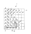
図5は、3つの隣接する他のアンテナパネルCへ位相情報が送信される例を示している。図5に示すように、3つの隣接する他のアンテナパネルCへ位相情報を送信することによって、通信機能が故障したアンテナパネルC2を回り込んで、通信機能が故障していないアンテナパネルC3へ位相情報が送信されることとなる。
なお、図5では、位相情報を送信する3つの隣接する他のアンテナパネルCに、位相情報を受信した他のアンテナパネルCを含まない。すなわち、アンテナパネルCは、位相情報を受信した他のアンテナパネルCにも、演算の結果としての位相情報を送信すると、4つの隣接する他のアンテナパネルCへ位相情報を送信することとなる。
図5は、3つの隣接する他のアンテナパネルCへ位相情報が送信される例を示している。図5に示すように、3つの隣接する他のアンテナパネルCへ位相情報を送信することによって、通信機能が故障したアンテナパネルC2を回り込んで、通信機能が故障していないアンテナパネルC3へ位相情報が送信されることとなる。
なお、図5では、位相情報を送信する3つの隣接する他のアンテナパネルCに、位相情報を受信した他のアンテナパネルCを含まない。すなわち、アンテナパネルCは、位相情報を受信した他のアンテナパネルCにも、演算の結果としての位相情報を送信すると、4つの隣接する他のアンテナパネルCへ位相情報を送信することとなる。
また、アンテナパネルCが備える送受信部94又は演算処理部50の故障により、誤った位相情報が、隣接する他のアンテナパネルCへ送信される場合がある。このような場合、誤った位相情報が他のパネルに伝播する可能性がある。
そこで、本実施形態に係る演算処理部50は、2つ以上の隣接する他のアンテナパネルCからの位相情報を受信した後に、受信した位相情報毎に複数の演算を行い、多数決により位相情報を決定する。そして、送受信部94は、多数決により決定した位相情報を隣接する他のアンテナパネルCへ送信する。すなわち、演算の結果として異なる位相情報が複数得られた場合、同一の位相情報がより多い方が、正しい位相情報として決定される。なお、同一の位相情報には、完全に同一な位相情報の他に、差が所定範囲内に含まれる位相情報も含まれる。
このように、アンテナパネルCが、他のアンテナパネルCから誤った位相情報を受信したとしても、他のアンテナパネルCから受信した正しい位相情報を用いて、位相情報を演算することとなるので、誤った位相情報が他のアンテナパネルCに更に送信されること、すなわち、誤った位相情報の伝播が防止される。
そこで、本実施形態に係る演算処理部50は、2つ以上の隣接する他のアンテナパネルCからの位相情報を受信した後に、受信した位相情報毎に複数の演算を行い、多数決により位相情報を決定する。そして、送受信部94は、多数決により決定した位相情報を隣接する他のアンテナパネルCへ送信する。すなわち、演算の結果として異なる位相情報が複数得られた場合、同一の位相情報がより多い方が、正しい位相情報として決定される。なお、同一の位相情報には、完全に同一な位相情報の他に、差が所定範囲内に含まれる位相情報も含まれる。
このように、アンテナパネルCが、他のアンテナパネルCから誤った位相情報を受信したとしても、他のアンテナパネルCから受信した正しい位相情報を用いて、位相情報を演算することとなるので、誤った位相情報が他のアンテナパネルCに更に送信されること、すなわち、誤った位相情報の伝播が防止される。
図6は、本実施形態に係る通信アルゴリズムの処理の流れを示す模式図である。なお、図6において、「A」を正しい位相情報とし、「B」を誤った位相情報とし、正しい位相情報「A」を用いた演算の結果としての位相情報を「A」とする。しかし、実際には、位相情報は、他のアンテナパネルCから受信した位相情報を用いて演算された結果であるため、演算の結果としての位相情報と受信した位相情報は異なる場合がある。
なお、基準パネルP及び基準パネルPに隣接し2つ以上の位相情報を受信できないアンテナパネルCは、通信アルゴリズムによる処理を行うことなく、位相情報を演算する。
なお、基準パネルP及び基準パネルPに隣接し2つ以上の位相情報を受信できないアンテナパネルCは、通信アルゴリズムによる処理を行うことなく、位相情報を演算する。
通信アルゴリズムでは、まず、演算処理部50が、2つの隣接する他のアンテナパネルCから位相情報を受信するまで待機する(ステップ1)。
そして、演算処理部50は、2つの隣接する他のアンテナパネルCからの位相情報を受信する(ステップ2)と、受信した位相情報毎に演算を行い(ステップ3A,3B,3C)、演算の結果としての2つの位相情報が一致するか否かを判定する。
そして、演算処理部50は、2つの隣接する他のアンテナパネルCからの位相情報を受信する(ステップ2)と、受信した位相情報毎に演算を行い(ステップ3A,3B,3C)、演算の結果としての2つの位相情報が一致するか否かを判定する。
演算の結果としての2つの位相情報が一致しない場合、すなわち、正しい位相情報「A」と誤った位相情報「B」とを受信した場合、演算処理部50は、位相情報の決定を保留し(ステップ3A)する。そして、送受信部94は、不一致を示す不一致情報(図6の「?」)を隣接する他のアンテナパネルCへ送信する(ステップ4A)。
そして、演算処理部50は、その後、隣接する他のアンテナパネルCから3つ目の位相情報を受信すると、3つ目の位相情報を用いて演算を行い、多数決により位相情報を決定する(ステップ5A)。
そして、送受信部94が、多数決によって決定された位相情報を隣接する他のアンテナパネルCへ新たに送信する(ステップ6)。
そして、演算処理部50は、その後、隣接する他のアンテナパネルCから3つ目の位相情報を受信すると、3つ目の位相情報を用いて演算を行い、多数決により位相情報を決定する(ステップ5A)。
そして、送受信部94が、多数決によって決定された位相情報を隣接する他のアンテナパネルCへ新たに送信する(ステップ6)。
一方、送受信部94が不一致情報「?」を受信した場合、演算処理部50は、受信した一つの位相情報「A」を用いて演算を行う(ステップ3B)。そして、送受信部94は、位相情報「A」を用いた演算の結果としての位相情報「A」を、隣接する他のアンテナパネルCへ送信する(ステップ6)。
また、2つの演算の結果としての位相情報「A」が一致した場合、すなわち、正しい位相情報「A」を2つ受信した場合(ステップ3C)、演算処理部50による位相情報毎の演算の結果としての2つの位相情報は、一致する。そのため、送受信部94は、一致した位相情報「A」を隣接する他のアンテナパネルCへ送信する(ステップ6)。
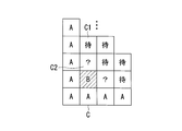
図7A~Dは、本実施形態に係る通信アルゴリズムの処理の具体的な一例を示す模式図である。アンテナパネルC上に表示されている「A」は、正しい位相情報を送信したアンテナパネルCを示し、「?」は、保留状態となっているアンテナパネルCを示している。また、「待」は、位相情報の受信待ち状態となっているアンテナパネルCを示し、「B」は、誤った位相情報を送信したアンテナパネルCを示している。
図7Aは、初期状態の一例である。
図7Bは、受信待ち状態となっているアンテナパネルC1が、位相情報「A」と位相情報「?」を受信し、演算の結果を位相情報「A」と決定した状態である。
図7Cは、アンテナパネルC1が、位相情報「A」を隣り合う他のアンテナパネルCへ送信した状態である。
図7Dは、保留状態となっていたアンテナパネルC2が、アンテナパネルC1から受信した位相情報「A」によって、演算の結果を位相情報「A」と決定し、決定した位相情報「A」を隣り合う他のアンテナパネルCへ送信した状態である。
図7Aは、初期状態の一例である。
図7Bは、受信待ち状態となっているアンテナパネルC1が、位相情報「A」と位相情報「?」を受信し、演算の結果を位相情報「A」と決定した状態である。
図7Cは、アンテナパネルC1が、位相情報「A」を隣り合う他のアンテナパネルCへ送信した状態である。
図7Dは、保留状態となっていたアンテナパネルC2が、アンテナパネルC1から受信した位相情報「A」によって、演算の結果を位相情報「A」と決定し、決定した位相情報「A」を隣り合う他のアンテナパネルCへ送信した状態である。
以上説明したように、本実施形態に係るフェーズドアレイアンテナ1は、各アンテナパネルC毎に備えられた演算処理部50によって、アンテナ素子20から放射させる送電マイクロ波の移相量を演算する。そして、演算処理部50で演算された移相量を示す位相情報は、各アンテナパネルC毎に備えられた送受信部94によって、少なくとも3つ以上の隣接する他のアンテナパネルCへ送信される。
従って、本実施形態に係るフェーズドアレイアンテナ1は、アンテナパネルCによる位相情報の送信に異常が生じても、該異常の影響が他のアンテナパネルCに伝播することを防止できる。
従って、本実施形態に係るフェーズドアレイアンテナ1は、アンテナパネルCによる位相情報の送信に異常が生じても、該異常の影響が他のアンテナパネルCに伝播することを防止できる。
また、本実施形態に係るフェーズドアレイアンテナ1は、アンテナパネルCが2つ以上の隣接する他のアンテナパネルCからの位相情報を受信すると、演算処理部50によって、受信した位相情報毎に複数の演算を行い、多数決により演算の結果としての位相情報を決定し、送受信部94によって、多数決により決定した位相情報を隣接する他のアンテナパネルCへ送信する。
従って、本実施形態に係るフェーズドアレイアンテナ1は、誤った位相情報が他のアンテナパネルCに更に送信されること、すなわち、誤った位相情報の伝播を防止できるので、アンテナパネルCによる位相情報の送信に異常が生じても、該異常の影響が他のアンテナパネルCに伝播することを防止できる。
従って、本実施形態に係るフェーズドアレイアンテナ1は、誤った位相情報が他のアンテナパネルCに更に送信されること、すなわち、誤った位相情報の伝播を防止できるので、アンテナパネルCによる位相情報の送信に異常が生じても、該異常の影響が他のアンテナパネルCに伝播することを防止できる。
また、本実施形態に係るフェーズドアレイアンテナ1は、隣接する他のアンテナパネルCからの位相情報を2つ受信すると、演算処理部50によって、受信した位相情報毎に演算を行い、演算の結果としての2つの位相情報が一致するか否かを判定し、2つの位相情報が一致しない場合に、送受信部94によって、不一致を示す不一致情報を隣接する他のアンテナパネルCへ送信する。
従って、本実施形態に係るフェーズドアレイアンテナ1は、演算の結果としての2つの位相情報の一致、不一致にかかわらず、隣接する他のアンテナパネルCへ情報を送信することとなるので、隣接する他のアンテナパネルCへの情報の送受信が滞ることを防ぐことができる。
従って、本実施形態に係るフェーズドアレイアンテナ1は、演算の結果としての2つの位相情報の一致、不一致にかかわらず、隣接する他のアンテナパネルCへ情報を送信することとなるので、隣接する他のアンテナパネルCへの情報の送受信が滞ることを防ぐことができる。
また、本実施形態に係るフェーズドアレイアンテナ1は、演算の結果としての2つの位相情報が一致せず、その後、隣接する他のアンテナパネルCから3つ目の位相情報を受信すると、演算処理部50によって、3つ目の位相情報を用いて演算を行い、多数決により演算の結果としての位相情報を決定し、送受信部94によって、多数決により決定された位相情報を隣接する他のアンテナパネルCへ新たに送信する。
従って、本実施形態に係るフェーズドアレイアンテナ1は、誤った位相情報の伝播を防止すると共に、正しい位相情報を伝播させることができる。
従って、本実施形態に係るフェーズドアレイアンテナ1は、誤った位相情報の伝播を防止すると共に、正しい位相情報を伝播させることができる。
以上、本発明を、上記実施形態を用いて説明したが、本発明の技術的範囲は上記実施形態に記載の範囲には限定されない。発明の要旨を逸脱しない範囲で上記実施形態に多様な変更または改良を加えることができ、該変更または改良を加えた形態も本発明の技術的範囲に含まれる。
例えば、上記実施形態では、位相情報を隣接する他のアンテナパネルCへ送信し、受信した位相情報を用いて演算する形態について説明したが、本発明は、これに限定されるものではなく、パイロット信号に基づいて演算したアンテナパネルCの位置を示す位置情報及びアンテナパネルCの角度を示す角度情報を隣接する他のアンテナパネルCへ送信し、受信した位置情報及び角度情報を用いて、アンテナ素子20から放射させる送電マイクロ波の移相量を演算する形態としてもよい。
また、上記実施形態では、正方形とされたアンテナパネルCの各辺に隣接する他のアンテナパネルC間で位相情報を送受信する形態について説明したが、本発明は、これに限定されるものではなく、アンテナパネルCの角で隣接する他のアンテナパネルC間で位相情報を送受信する形態としてもよい。この形態の場合、5つ以上の隣接する他のアンテナパネルCへの位相情報の送信が可能となる。
また、上記実施形態では、アンテナパネルCを正方形とする形態について説明したが、本発明は、これに限定されるものではなく、アンテナパネルCを五角形以上の多角形とする形態としてもよい。この形態の場合、5つ以上の隣接する他のアンテナパネルCへの位相情報の送信が可能となる。
1 フェーズドアレイアンテナ
50 演算処理部
51 位置特定部
52 移相量決定部
92 位相制御部
94 送受信部
120 受電設備
C アンテナパネル
50 演算処理部
51 位置特定部
52 移相量決定部
92 位相制御部
94 送受信部
120 受電設備
C アンテナパネル
Claims (5)
- 複数のアンテナ素子が配列配置された複数のアンテナパネルを平面状に接続した構成を有し、各前記アンテナ素子に入出力する信号の位相を制御することにより、受電設備から送信されたパイロット信号の到来方向に対し信号を放射するフェーズドアレイアンテナであって、
各前記アンテナパネル毎に備えられ、前記アンテナ素子から放射させる信号の移相量を演算する演算手段と、
各前記アンテナパネル毎に備えられ、前記演算手段による前記移相量の演算に用いる演算情報を隣接する他の前記アンテナパネルから受信する受信手段と、
各前記アンテナパネル毎に備えられ、少なくとも3つ以上の隣接する他の前記アンテナパネルへ、前記演算手段によって演算した前記演算情報を送信する送信手段と、
を備えたフェーズドアレイアンテナ。 - 前記演算手段は、2つ以上の隣接する他の前記アンテナパネルからの前記演算情報を受信した後に、受信した前記演算情報毎に複数の演算を行い、多数決により演算の結果としての前記演算情報を決定し、
前記送信手段は、多数決により決定された前記演算情報を隣接する他の前記アンテナパネルへ送信する請求項1記載のフェーズドアレイアンテナ。 - 前記演算手段は、隣接する他の前記アンテナパネルからの前記演算情報を2つ受信すると、受信した前記演算情報毎に演算を行い、演算の結果としての2つの前記演算情報が一致するか否かを判定し、
前記送信手段は、2つの前記演算情報が一致しない場合、不一致を示す不一致情報を隣接する他の前記アンテナパネルへ送信し、2つの前記演算情報が一致した場合、該演算情報を隣接する他の前記アンテナパネルへ送信する請求項2記載のフェーズドアレイアンテナ。 - 前記演算手段は、演算の結果としての2つの前記演算情報が一致せず、その後、隣接する他の前記アンテナパネルから3つ目の前記演算情報を受信すると、該3つ目の前記演算情報を用いて演算を行い、多数決により演算情報を決定し、
前記送信手段は、多数決により決定された前記演算情報を、隣接する他の前記アンテナパネルへ新たに送信する請求項3記載のフェーズドアレイアンテナ。 - 複数のアンテナ素子が配列配置された複数のアンテナパネルを平面状に接続した構成を有し、各前記アンテナ素子に入出力する信号の位相を制御することにより、受電設備から送信されたパイロット信号の到来方向に対し信号を放射するフェーズドアレイアンテナの位相制御方法であって、
各前記アンテナパネル毎に備えられた受信手段によって、前記アンテナ素子から放射させる信号の移相量の演算に用いる演算情報を隣接する他の前記アンテナパネルから受信し、該演算情報を用いて前記移相量を演算する第1工程と、
各前記アンテナパネル毎に備えられた送信手段によって、少なくとも3つ以上の隣接する他の前記アンテナパネルへ前記第1工程で演算した前記演算情報を送信する第2工程と、
を含むフェーズドアレイアンテナの位相制御方法。
Priority Applications (1)
| Application Number | Priority Date | Filing Date | Title |
|---|---|---|---|
| US14/113,096 US9568936B2 (en) | 2011-07-27 | 2012-07-13 | Phased array antenna and phase control method therefor |
Applications Claiming Priority (2)
| Application Number | Priority Date | Filing Date | Title |
|---|---|---|---|
| JP2011164520A JP5769533B2 (ja) | 2011-07-27 | 2011-07-27 | フェーズドアレイアンテナ及びその位相制御方法 |
| JP2011-164520 | 2011-07-27 |
Publications (1)
| Publication Number | Publication Date |
|---|---|
| WO2013015137A1 true WO2013015137A1 (ja) | 2013-01-31 |
Family
ID=47600988
Family Applications (1)
| Application Number | Title | Priority Date | Filing Date |
|---|---|---|---|
| PCT/JP2012/067920 Ceased WO2013015137A1 (ja) | 2011-07-27 | 2012-07-13 | フェーズドアレイアンテナ及びその位相制御方法 |
Country Status (3)
| Country | Link |
|---|---|
| US (1) | US9568936B2 (ja) |
| JP (1) | JP5769533B2 (ja) |
| WO (1) | WO2013015137A1 (ja) |
Families Citing this family (6)
| Publication number | Priority date | Publication date | Assignee | Title |
|---|---|---|---|---|
| JP2014211767A (ja) * | 2013-04-18 | 2014-11-13 | 富士通株式会社 | 情報処理システム、制御装置及び情報処理システムの制御方法 |
| JP6207365B2 (ja) * | 2013-12-02 | 2017-10-04 | 三菱電機株式会社 | フェーズドアレーアンテナ装置及び通信システム |
| US11169240B1 (en) | 2018-11-30 | 2021-11-09 | Ball Aerospace & Technologies Corp. | Systems and methods for determining an angle of arrival of a signal at a planar array antenna |
| US11327142B2 (en) | 2019-03-29 | 2022-05-10 | Ball Aerospace & Technologies Corp. | Systems and methods for locating and tracking radio frequency transmitters |
| CN113395098B (zh) * | 2021-04-13 | 2023-11-03 | 西安宇飞电子技术有限公司 | 一种多天线信号合并和发射信号赋形的方法及装置 |
| WO2023287956A1 (en) * | 2021-07-14 | 2023-01-19 | Times Fiber Communications, Inc. | Provider equipment identification |
Citations (4)
| Publication number | Priority date | Publication date | Assignee | Title |
|---|---|---|---|---|
| JP2001309581A (ja) * | 2000-04-24 | 2001-11-02 | Mitsubishi Electric Corp | 宇宙太陽光発電方法、そのシステム、発電衛星、制御衛星及び電力基地 |
| JP2004325162A (ja) * | 2003-04-23 | 2004-11-18 | Mitsubishi Heavy Ind Ltd | 位相計測装置及び宇宙太陽発電システム |
| JP2005506788A (ja) * | 2001-10-22 | 2005-03-03 | キネテイツク・リミテツド | アンテナシステム |
| JP2006304205A (ja) * | 2005-04-25 | 2006-11-02 | Nippon Hoso Kyokai <Nhk> | アンテナ位相較正装置及びそれを用いた追尾アンテナ装置 |
Family Cites Families (7)
| Publication number | Priority date | Publication date | Assignee | Title |
|---|---|---|---|---|
| US3005168A (en) * | 1959-10-08 | 1961-10-17 | David L Fye | Microwave phase shifter |
| US4227194A (en) * | 1971-01-04 | 1980-10-07 | Hughes Aircraft Company | Synthetic array processor |
| CA1238713A (en) * | 1984-06-04 | 1988-06-28 | Alliedsignal Inc. | Antenna feed network |
| US4717918A (en) * | 1985-08-23 | 1988-01-05 | Harris Corporation | Phased array antenna |
| JPH11145725A (ja) * | 1997-11-11 | 1999-05-28 | Tech Res & Dev Inst Of Japan Def Agency | 空間給電フェーズドアレイアンテナ装置 |
| JP2002100919A (ja) * | 2000-09-25 | 2002-04-05 | Toshiba Corp | フェーズドアレイアンテナ装置 |
| JP4486539B2 (ja) * | 2005-03-31 | 2010-06-23 | 三菱重工業株式会社 | フェーズドアレイアンテナ及びその位相制御方法 |
-
2011
- 2011-07-27 JP JP2011164520A patent/JP5769533B2/ja not_active Expired - Fee Related
-
2012
- 2012-07-13 US US14/113,096 patent/US9568936B2/en not_active Expired - Fee Related
- 2012-07-13 WO PCT/JP2012/067920 patent/WO2013015137A1/ja not_active Ceased
Patent Citations (4)
| Publication number | Priority date | Publication date | Assignee | Title |
|---|---|---|---|---|
| JP2001309581A (ja) * | 2000-04-24 | 2001-11-02 | Mitsubishi Electric Corp | 宇宙太陽光発電方法、そのシステム、発電衛星、制御衛星及び電力基地 |
| JP2005506788A (ja) * | 2001-10-22 | 2005-03-03 | キネテイツク・リミテツド | アンテナシステム |
| JP2004325162A (ja) * | 2003-04-23 | 2004-11-18 | Mitsubishi Heavy Ind Ltd | 位相計測装置及び宇宙太陽発電システム |
| JP2006304205A (ja) * | 2005-04-25 | 2006-11-02 | Nippon Hoso Kyokai <Nhk> | アンテナ位相較正装置及びそれを用いた追尾アンテナ装置 |
Also Published As
| Publication number | Publication date |
|---|---|
| JP2013030914A (ja) | 2013-02-07 |
| JP5769533B2 (ja) | 2015-08-26 |
| US20140035694A1 (en) | 2014-02-06 |
| US9568936B2 (en) | 2017-02-14 |
Similar Documents
| Publication | Publication Date | Title |
|---|---|---|
| JP5336709B2 (ja) | 電力供給システム | |
| JP5769533B2 (ja) | フェーズドアレイアンテナ及びその位相制御方法 | |
| US12231178B2 (en) | Over-the-air calibration of antenna system | |
| US8154452B2 (en) | Method and apparatus for phased array antenna field recalibration | |
| US8264398B2 (en) | Onboard radar device and program of controlling onboard radar device | |
| CN111937328B (zh) | Oam复用通信系统的天线位置偏移校正方法以及装置 | |
| ITBO20090046A1 (it) | Sistema di posizionamento per veicoli a guida automatica funzionante a radio frequenza con antenne direttive | |
| US20110291889A1 (en) | Phased array antenna and a method of operating a phased array antenna | |
| WO2010059759A3 (en) | Systems and methods for compensating for transmission phasing errors in a communications system using a receive signal | |
| JP5161904B2 (ja) | フェーズドアレイアンテナ及びその位相制御方法 | |
| CN105122545A (zh) | 具有可变方向特性的天线装置 | |
| CN104701637A (zh) | 基于机电耦合与最小二乘法的变形阵列天线电性能补偿方法 | |
| KR101217134B1 (ko) | 다항식 곡선접합 보정방식의 능동형 위상 배열 레이더 시스템 | |
| CN106507895B (zh) | 一种导引头天线罩瞄准误差补偿方法 | |
| JP4486539B2 (ja) | フェーズドアレイアンテナ及びその位相制御方法 | |
| JP5578885B2 (ja) | フェーズドアレイアンテナ及びその制御方法 | |
| JPH0837743A (ja) | マイクロ波送電装置 | |
| CN102725968A (zh) | 微波天线对准方法及装置 | |
| CN102394686A (zh) | 高精度阵列天线接收系统角度估计的装置及其方法 | |
| US12113608B2 (en) | Transmission of atmospheric ducted communication signals | |
| JP3616075B2 (ja) | 送電ビーム方向制御装置 | |
| CN111736120A (zh) | 一种基于天波传播校正源信号的阵列误差校正方法 | |
| JP7080415B2 (ja) | 指向方向制御装置、光通信ターミナル、光通信システム、及び指向方向制御方法 | |
| JP6121095B2 (ja) | 送電装置及び無線電力伝送システム | |
| US9647333B2 (en) | Array antenna, configuration method, and communication system |
Legal Events
| Date | Code | Title | Description |
|---|---|---|---|
| 121 | Ep: the epo has been informed by wipo that ep was designated in this application |
Ref document number: 12817663 Country of ref document: EP Kind code of ref document: A1 |
|
| WWE | Wipo information: entry into national phase |
Ref document number: 14113096 Country of ref document: US |
|
| NENP | Non-entry into the national phase |
Ref country code: DE |
|
| 122 | Ep: pct application non-entry in european phase |
Ref document number: 12817663 Country of ref document: EP Kind code of ref document: A1 |