WO2013014992A1 - Matériau composite renforcé par des fibres - Google Patents
Matériau composite renforcé par des fibres Download PDFInfo
- Publication number
- WO2013014992A1 WO2013014992A1 PCT/JP2012/061966 JP2012061966W WO2013014992A1 WO 2013014992 A1 WO2013014992 A1 WO 2013014992A1 JP 2012061966 W JP2012061966 W JP 2012061966W WO 2013014992 A1 WO2013014992 A1 WO 2013014992A1
- Authority
- WO
- WIPO (PCT)
- Prior art keywords
- fiber
- fiber bundle
- layer
- composite material
- layers
- Prior art date
Links
- 239000000463 material Substances 0.000 title claims abstract description 104
- 239000003733 fiber-reinforced composite Substances 0.000 title claims abstract description 97
- 239000000835 fiber Substances 0.000 claims abstract description 342
- 238000010030 laminating Methods 0.000 claims abstract description 13
- 239000011159 matrix material Substances 0.000 claims abstract description 11
- 239000002759 woven fabric Substances 0.000 claims description 20
- 239000012783 reinforcing fiber Substances 0.000 claims description 19
- 229920005989 resin Polymers 0.000 claims description 18
- 239000011347 resin Substances 0.000 claims description 18
- 238000004519 manufacturing process Methods 0.000 claims description 14
- 239000004744 fabric Substances 0.000 claims description 13
- 229920001187 thermosetting polymer Polymers 0.000 claims description 7
- 238000010438 heat treatment Methods 0.000 claims description 3
- 230000007935 neutral effect Effects 0.000 abstract description 29
- 238000010586 diagram Methods 0.000 description 9
- 238000005452 bending Methods 0.000 description 7
- 230000000704 physical effect Effects 0.000 description 7
- 230000003014 reinforcing effect Effects 0.000 description 7
- 229920000049 Carbon (fiber) Polymers 0.000 description 6
- 239000004917 carbon fiber Substances 0.000 description 6
- 238000000034 method Methods 0.000 description 6
- 238000003475 lamination Methods 0.000 description 4
- VNWKTOKETHGBQD-UHFFFAOYSA-N methane Chemical compound C VNWKTOKETHGBQD-UHFFFAOYSA-N 0.000 description 4
- 238000000465 moulding Methods 0.000 description 4
- 230000002787 reinforcement Effects 0.000 description 4
- 230000000694 effects Effects 0.000 description 3
- 239000003822 epoxy resin Substances 0.000 description 3
- 229920000647 polyepoxide Polymers 0.000 description 3
- 238000003303 reheating Methods 0.000 description 3
- OKTJSMMVPCPJKN-UHFFFAOYSA-N Carbon Chemical compound [C] OKTJSMMVPCPJKN-UHFFFAOYSA-N 0.000 description 2
- 229910052799 carbon Inorganic materials 0.000 description 2
- 239000002131 composite material Substances 0.000 description 2
- 238000006073 displacement reaction Methods 0.000 description 2
- 238000005470 impregnation Methods 0.000 description 2
- 239000012779 reinforcing material Substances 0.000 description 2
- 238000005728 strengthening Methods 0.000 description 2
- ICXAPFWGVRTEKV-UHFFFAOYSA-N 2-[4-(1,3-benzoxazol-2-yl)phenyl]-1,3-benzoxazole Chemical compound C1=CC=C2OC(C3=CC=C(C=C3)C=3OC4=CC=CC=C4N=3)=NC2=C1 ICXAPFWGVRTEKV-UHFFFAOYSA-N 0.000 description 1
- 240000001973 Ficus microcarpa Species 0.000 description 1
- 239000004699 Ultra-high molecular weight polyethylene Substances 0.000 description 1
- 239000000853 adhesive Substances 0.000 description 1
- 230000001070 adhesive effect Effects 0.000 description 1
- 239000004760 aramid Substances 0.000 description 1
- 229920006231 aramid fiber Polymers 0.000 description 1
- 238000010000 carbonizing Methods 0.000 description 1
- 230000000052 comparative effect Effects 0.000 description 1
- 230000007423 decrease Effects 0.000 description 1
- 238000010304 firing Methods 0.000 description 1
- 239000003365 glass fiber Substances 0.000 description 1
- 239000002241 glass-ceramic Substances 0.000 description 1
- 239000012784 inorganic fiber Substances 0.000 description 1
- 239000007788 liquid Substances 0.000 description 1
- 239000002184 metal Substances 0.000 description 1
- 239000005011 phenolic resin Substances 0.000 description 1
- 230000002040 relaxant effect Effects 0.000 description 1
- 238000007493 shaping process Methods 0.000 description 1
- 238000001721 transfer moulding Methods 0.000 description 1
- 229920000785 ultra high molecular weight polyethylene Polymers 0.000 description 1
- 229920006337 unsaturated polyester resin Polymers 0.000 description 1
Images


Classifications
-
- B—PERFORMING OPERATIONS; TRANSPORTING
- B32—LAYERED PRODUCTS
- B32B—LAYERED PRODUCTS, i.e. PRODUCTS BUILT-UP OF STRATA OF FLAT OR NON-FLAT, e.g. CELLULAR OR HONEYCOMB, FORM
- B32B5/00—Layered products characterised by the non- homogeneity or physical structure, i.e. comprising a fibrous, filamentary, particulate or foam layer; Layered products characterised by having a layer differing constitutionally or physically in different parts
- B32B5/02—Layered products characterised by the non- homogeneity or physical structure, i.e. comprising a fibrous, filamentary, particulate or foam layer; Layered products characterised by having a layer differing constitutionally or physically in different parts characterised by structural features of a fibrous or filamentary layer
- B32B5/12—Layered products characterised by the non- homogeneity or physical structure, i.e. comprising a fibrous, filamentary, particulate or foam layer; Layered products characterised by having a layer differing constitutionally or physically in different parts characterised by structural features of a fibrous or filamentary layer characterised by the relative arrangement of fibres or filaments of different layers, e.g. the fibres or filaments being parallel or perpendicular to each other
-
- B—PERFORMING OPERATIONS; TRANSPORTING
- B29—WORKING OF PLASTICS; WORKING OF SUBSTANCES IN A PLASTIC STATE IN GENERAL
- B29C—SHAPING OR JOINING OF PLASTICS; SHAPING OF MATERIAL IN A PLASTIC STATE, NOT OTHERWISE PROVIDED FOR; AFTER-TREATMENT OF THE SHAPED PRODUCTS, e.g. REPAIRING
- B29C70/00—Shaping composites, i.e. plastics material comprising reinforcements, fillers or preformed parts, e.g. inserts
- B29C70/04—Shaping composites, i.e. plastics material comprising reinforcements, fillers or preformed parts, e.g. inserts comprising reinforcements only, e.g. self-reinforcing plastics
- B29C70/06—Fibrous reinforcements only
- B29C70/10—Fibrous reinforcements only characterised by the structure of fibrous reinforcements, e.g. hollow fibres
- B29C70/16—Fibrous reinforcements only characterised by the structure of fibrous reinforcements, e.g. hollow fibres using fibres of substantial or continuous length
- B29C70/22—Fibrous reinforcements only characterised by the structure of fibrous reinforcements, e.g. hollow fibres using fibres of substantial or continuous length oriented in at least two directions forming a two dimensional structure
- B29C70/222—Fibrous reinforcements only characterised by the structure of fibrous reinforcements, e.g. hollow fibres using fibres of substantial or continuous length oriented in at least two directions forming a two dimensional structure the structure being shaped to form a three dimensional configuration
-
- B—PERFORMING OPERATIONS; TRANSPORTING
- B29—WORKING OF PLASTICS; WORKING OF SUBSTANCES IN A PLASTIC STATE IN GENERAL
- B29C—SHAPING OR JOINING OF PLASTICS; SHAPING OF MATERIAL IN A PLASTIC STATE, NOT OTHERWISE PROVIDED FOR; AFTER-TREATMENT OF THE SHAPED PRODUCTS, e.g. REPAIRING
- B29C70/00—Shaping composites, i.e. plastics material comprising reinforcements, fillers or preformed parts, e.g. inserts
- B29C70/04—Shaping composites, i.e. plastics material comprising reinforcements, fillers or preformed parts, e.g. inserts comprising reinforcements only, e.g. self-reinforcing plastics
- B29C70/06—Fibrous reinforcements only
- B29C70/10—Fibrous reinforcements only characterised by the structure of fibrous reinforcements, e.g. hollow fibres
- B29C70/16—Fibrous reinforcements only characterised by the structure of fibrous reinforcements, e.g. hollow fibres using fibres of substantial or continuous length
- B29C70/22—Fibrous reinforcements only characterised by the structure of fibrous reinforcements, e.g. hollow fibres using fibres of substantial or continuous length oriented in at least two directions forming a two dimensional structure
- B29C70/228—Fibrous reinforcements only characterised by the structure of fibrous reinforcements, e.g. hollow fibres using fibres of substantial or continuous length oriented in at least two directions forming a two dimensional structure the structure being stacked in parallel layers with fibres of adjacent layers crossing at substantial angles
-
- B—PERFORMING OPERATIONS; TRANSPORTING
- B29—WORKING OF PLASTICS; WORKING OF SUBSTANCES IN A PLASTIC STATE IN GENERAL
- B29C—SHAPING OR JOINING OF PLASTICS; SHAPING OF MATERIAL IN A PLASTIC STATE, NOT OTHERWISE PROVIDED FOR; AFTER-TREATMENT OF THE SHAPED PRODUCTS, e.g. REPAIRING
- B29C70/00—Shaping composites, i.e. plastics material comprising reinforcements, fillers or preformed parts, e.g. inserts
- B29C70/04—Shaping composites, i.e. plastics material comprising reinforcements, fillers or preformed parts, e.g. inserts comprising reinforcements only, e.g. self-reinforcing plastics
- B29C70/28—Shaping operations therefor
- B29C70/30—Shaping by lay-up, i.e. applying fibres, tape or broadsheet on a mould, former or core; Shaping by spray-up, i.e. spraying of fibres on a mould, former or core
- B29C70/34—Shaping by lay-up, i.e. applying fibres, tape or broadsheet on a mould, former or core; Shaping by spray-up, i.e. spraying of fibres on a mould, former or core and shaping or impregnating by compression, i.e. combined with compressing after the lay-up operation
-
- B—PERFORMING OPERATIONS; TRANSPORTING
- B32—LAYERED PRODUCTS
- B32B—LAYERED PRODUCTS, i.e. PRODUCTS BUILT-UP OF STRATA OF FLAT OR NON-FLAT, e.g. CELLULAR OR HONEYCOMB, FORM
- B32B5/00—Layered products characterised by the non- homogeneity or physical structure, i.e. comprising a fibrous, filamentary, particulate or foam layer; Layered products characterised by having a layer differing constitutionally or physically in different parts
- B32B5/02—Layered products characterised by the non- homogeneity or physical structure, i.e. comprising a fibrous, filamentary, particulate or foam layer; Layered products characterised by having a layer differing constitutionally or physically in different parts characterised by structural features of a fibrous or filamentary layer
- B32B5/024—Woven fabric
-
- B—PERFORMING OPERATIONS; TRANSPORTING
- B64—AIRCRAFT; AVIATION; COSMONAUTICS
- B64C—AEROPLANES; HELICOPTERS
- B64C1/00—Fuselages; Constructional features common to fuselages, wings, stabilising surfaces or the like
- B64C1/06—Frames; Stringers; Longerons ; Fuselage sections
- B64C1/064—Stringers; Longerons
-
- B—PERFORMING OPERATIONS; TRANSPORTING
- B64—AIRCRAFT; AVIATION; COSMONAUTICS
- B64C—AEROPLANES; HELICOPTERS
- B64C1/00—Fuselages; Constructional features common to fuselages, wings, stabilising surfaces or the like
- B64C1/06—Frames; Stringers; Longerons ; Fuselage sections
- B64C1/12—Construction or attachment of skin panels
-
- B—PERFORMING OPERATIONS; TRANSPORTING
- B64—AIRCRAFT; AVIATION; COSMONAUTICS
- B64C—AEROPLANES; HELICOPTERS
- B64C3/00—Wings
- B64C3/18—Spars; Ribs; Stringers
- B64C3/182—Stringers, longerons
-
- B—PERFORMING OPERATIONS; TRANSPORTING
- B64—AIRCRAFT; AVIATION; COSMONAUTICS
- B64C—AEROPLANES; HELICOPTERS
- B64C3/00—Wings
- B64C3/20—Integral or sandwich constructions
-
- B—PERFORMING OPERATIONS; TRANSPORTING
- B64—AIRCRAFT; AVIATION; COSMONAUTICS
- B64C—AEROPLANES; HELICOPTERS
- B64C3/00—Wings
- B64C3/26—Construction, shape, or attachment of separate skins, e.g. panels
-
- B—PERFORMING OPERATIONS; TRANSPORTING
- B29—WORKING OF PLASTICS; WORKING OF SUBSTANCES IN A PLASTIC STATE IN GENERAL
- B29K—INDEXING SCHEME ASSOCIATED WITH SUBCLASSES B29B, B29C OR B29D, RELATING TO MOULDING MATERIALS OR TO MATERIALS FOR MOULDS, REINFORCEMENTS, FILLERS OR PREFORMED PARTS, e.g. INSERTS
- B29K2105/00—Condition, form or state of moulded material or of the material to be shaped
- B29K2105/06—Condition, form or state of moulded material or of the material to be shaped containing reinforcements, fillers or inserts
- B29K2105/08—Condition, form or state of moulded material or of the material to be shaped containing reinforcements, fillers or inserts of continuous length, e.g. cords, rovings, mats, fabrics, strands or yarns
- B29K2105/0872—Prepregs
- B29K2105/089—Prepregs fabric
-
- B—PERFORMING OPERATIONS; TRANSPORTING
- B32—LAYERED PRODUCTS
- B32B—LAYERED PRODUCTS, i.e. PRODUCTS BUILT-UP OF STRATA OF FLAT OR NON-FLAT, e.g. CELLULAR OR HONEYCOMB, FORM
- B32B2250/00—Layers arrangement
- B32B2250/40—Symmetrical or sandwich layers, e.g. ABA, ABCBA, ABCCBA
-
- B—PERFORMING OPERATIONS; TRANSPORTING
- B32—LAYERED PRODUCTS
- B32B—LAYERED PRODUCTS, i.e. PRODUCTS BUILT-UP OF STRATA OF FLAT OR NON-FLAT, e.g. CELLULAR OR HONEYCOMB, FORM
- B32B2260/00—Layered product comprising an impregnated, embedded, or bonded layer wherein the layer comprises an impregnation, embedding, or binder material
- B32B2260/02—Composition of the impregnated, bonded or embedded layer
- B32B2260/021—Fibrous or filamentary layer
- B32B2260/023—Two or more layers
-
- B—PERFORMING OPERATIONS; TRANSPORTING
- B32—LAYERED PRODUCTS
- B32B—LAYERED PRODUCTS, i.e. PRODUCTS BUILT-UP OF STRATA OF FLAT OR NON-FLAT, e.g. CELLULAR OR HONEYCOMB, FORM
- B32B2260/00—Layered product comprising an impregnated, embedded, or bonded layer wherein the layer comprises an impregnation, embedding, or binder material
- B32B2260/04—Impregnation, embedding, or binder material
- B32B2260/046—Synthetic resin
-
- B—PERFORMING OPERATIONS; TRANSPORTING
- B32—LAYERED PRODUCTS
- B32B—LAYERED PRODUCTS, i.e. PRODUCTS BUILT-UP OF STRATA OF FLAT OR NON-FLAT, e.g. CELLULAR OR HONEYCOMB, FORM
- B32B2262/00—Composition or structural features of fibres which form a fibrous or filamentary layer or are present as additives
- B32B2262/02—Synthetic macromolecular fibres
-
- B—PERFORMING OPERATIONS; TRANSPORTING
- B32—LAYERED PRODUCTS
- B32B—LAYERED PRODUCTS, i.e. PRODUCTS BUILT-UP OF STRATA OF FLAT OR NON-FLAT, e.g. CELLULAR OR HONEYCOMB, FORM
- B32B2262/00—Composition or structural features of fibres which form a fibrous or filamentary layer or are present as additives
- B32B2262/10—Inorganic fibres
- B32B2262/106—Carbon fibres, e.g. graphite fibres
-
- B—PERFORMING OPERATIONS; TRANSPORTING
- B32—LAYERED PRODUCTS
- B32B—LAYERED PRODUCTS, i.e. PRODUCTS BUILT-UP OF STRATA OF FLAT OR NON-FLAT, e.g. CELLULAR OR HONEYCOMB, FORM
- B32B2305/00—Condition, form or state of the layers or laminate
- B32B2305/07—Parts immersed or impregnated in a matrix
- B32B2305/076—Prepregs
-
- B—PERFORMING OPERATIONS; TRANSPORTING
- B32—LAYERED PRODUCTS
- B32B—LAYERED PRODUCTS, i.e. PRODUCTS BUILT-UP OF STRATA OF FLAT OR NON-FLAT, e.g. CELLULAR OR HONEYCOMB, FORM
- B32B2605/00—Vehicles
- B32B2605/18—Aircraft
-
- B—PERFORMING OPERATIONS; TRANSPORTING
- B64—AIRCRAFT; AVIATION; COSMONAUTICS
- B64C—AEROPLANES; HELICOPTERS
- B64C1/00—Fuselages; Constructional features common to fuselages, wings, stabilising surfaces or the like
- B64C2001/0054—Fuselage structures substantially made from particular materials
- B64C2001/0072—Fuselage structures substantially made from particular materials from composite materials
-
- Y—GENERAL TAGGING OF NEW TECHNOLOGICAL DEVELOPMENTS; GENERAL TAGGING OF CROSS-SECTIONAL TECHNOLOGIES SPANNING OVER SEVERAL SECTIONS OF THE IPC; TECHNICAL SUBJECTS COVERED BY FORMER USPC CROSS-REFERENCE ART COLLECTIONS [XRACs] AND DIGESTS
- Y02—TECHNOLOGIES OR APPLICATIONS FOR MITIGATION OR ADAPTATION AGAINST CLIMATE CHANGE
- Y02T—CLIMATE CHANGE MITIGATION TECHNOLOGIES RELATED TO TRANSPORTATION
- Y02T50/00—Aeronautics or air transport
- Y02T50/40—Weight reduction
-
- Y—GENERAL TAGGING OF NEW TECHNOLOGICAL DEVELOPMENTS; GENERAL TAGGING OF CROSS-SECTIONAL TECHNOLOGIES SPANNING OVER SEVERAL SECTIONS OF THE IPC; TECHNICAL SUBJECTS COVERED BY FORMER USPC CROSS-REFERENCE ART COLLECTIONS [XRACs] AND DIGESTS
- Y10—TECHNICAL SUBJECTS COVERED BY FORMER USPC
- Y10T—TECHNICAL SUBJECTS COVERED BY FORMER US CLASSIFICATION
- Y10T156/00—Adhesive bonding and miscellaneous chemical manufacture
- Y10T156/10—Methods of surface bonding and/or assembly therefor
- Y10T156/1002—Methods of surface bonding and/or assembly therefor with permanent bending or reshaping or surface deformation of self sustaining lamina
- Y10T156/1043—Subsequent to assembly
- Y10T156/1044—Subsequent to assembly of parallel stacked sheets only
-
- Y—GENERAL TAGGING OF NEW TECHNOLOGICAL DEVELOPMENTS; GENERAL TAGGING OF CROSS-SECTIONAL TECHNOLOGIES SPANNING OVER SEVERAL SECTIONS OF THE IPC; TECHNICAL SUBJECTS COVERED BY FORMER USPC CROSS-REFERENCE ART COLLECTIONS [XRACs] AND DIGESTS
- Y10—TECHNICAL SUBJECTS COVERED BY FORMER USPC
- Y10T—TECHNICAL SUBJECTS COVERED BY FORMER US CLASSIFICATION
- Y10T428/00—Stock material or miscellaneous articles
- Y10T428/24—Structurally defined web or sheet [e.g., overall dimension, etc.]
- Y10T428/24058—Structurally defined web or sheet [e.g., overall dimension, etc.] including grain, strips, or filamentary elements in respective layers or components in angular relation
- Y10T428/24124—Fibers
Definitions
- the present invention relates to a fiber reinforced composite material configured by combining a laminated fiber bundle layer and a matrix.
- a fiber-reinforced composite material is used as a lightweight, high-strength material.
- the fiber reinforced composite material is configured by combining reinforcing fibers with a matrix of resin, metal, or the like. For this reason, the mechanical properties (mechanical properties) of the fiber reinforced composite material are improved over those of the matrix. Therefore, the fiber reinforced composite material is suitable for structural parts such as aircraft bodies and wings.
- the fiber-reinforced composite material can be made lighter.
- a laminated reinforcing material in which a plurality of fiber bundle layers made of fibers arranged in one direction is laminated is used. In this case, the plurality of fiber bundle layers function as a reinforcing fiber base material and are laminated with different arrangement directions of the fiber bundle layers.
- a fabric is formed using fibers having different torsional moments, and the generated moments are canceled (for example, see Patent Document 1).
- the thickness of the isotropic composite material is reduced compared to the case where a plurality of fiber sheets are laminated while changing the fiber orientation angle by 15 °, 30 °, 45 °, or 90 °. be able to.
- the fiber orientation angle ⁇ between adjacent fiber sheets among the laminated fiber sheets is 60 ° ⁇ ⁇ 90 °.
- the case of reverse symmetry as shown in the following table is also shown. Inverse symmetry means a case where the positive and negative of the laminated pattern are reversed across the reference plane.
- the reference surface is a surface on which fiber sheets having a laminated pattern of 0 ° are arranged.
- FIG. 8A shows a fiber-reinforced composite material 51 having a skin-web structure constituted by three sets of symmetrical laminated sheets 52. According to this structure, the two symmetrical laminated sheets 52 are each bent, and the skin part 53 and the web part 54 are comprised. As shown in FIG.
- FIG. 8C shows a case where the signs of the uppermost fiber orientation angle 45 ° layers are the same in the skin portion 53 of the symmetrical laminated sheet 52 arranged on the left side and the right side, respectively.
- the sign of the 45 ° fiber orientation angle layer of each symmetrical laminated sheet 52 is reversed with the opposing surface of the left symmetrical laminated sheet 52 and the right symmetrical laminated sheet 52 as a boundary. As a result, the fiber reinforced composite material 51 is twisted.
- An object of the present invention is to provide a fiber-reinforced composite material capable of reducing warpage without performing a special manufacturing method even in a complicated shape such as a skin-web structure.
- a fiber reinforced composite material configured by impregnating a matrix into a laminated fiber bundle layer obtained by laminating a plurality of fiber bundle layers made of reinforcing fibers.
- the number of + ⁇ layers that are fiber bundle layers with a fiber orientation angle of + ⁇ and the number of ⁇ layers that are fiber bundle layers with a fiber orientation angle of ⁇ are provided on both sides of the reference plane.
- the stacking order of the fiber bundle layers is inversely symmetric with respect to the reference plane, and other fiber bundle layers disposed between the + ⁇ layer and the ⁇ layer on both sides sandwiching the reference plane.
- the number of is the same.
- the fiber bundle layer having a fiber orientation angle of ⁇ and the fiber bundle layer having a fiber orientation angle of + ⁇ are arranged to be inversely symmetric with respect to the reference plane and satisfy the above condition. .
- the torsional moment due to the ⁇ layer and the + ⁇ layer is canceled out, so that the total synthetic moment is reduced. Therefore, even if the fiber-reinforced composite material has a complicated shape such as a skin-web structure, the warp of the fiber-reinforced composite material can be reduced without performing a special manufacturing method.
- the reference plane is a plane virtually existing between arbitrary fiber bundle layers of the laminated fiber bundle layer.
- the fiber orientation angle indicates an angle with respect to the longitudinal direction of the laminated fiber bundle layer.
- the above fiber reinforced composite material there are two + ⁇ layers and two ⁇ layers on both sides sandwiching the reference plane, and as a stacking order of the fiber bundle layers, one of the two sides sandwiching the reference plane has two + ⁇ layers.
- two - ⁇ layers are disposed between the two layers, and on the other hand, two + ⁇ layers are disposed between the two - ⁇ layers.
- ⁇ is preferably 45 °.
- a quasi-isotropic fiber reinforced composite is used.
- the material can be easily obtained.
- the + ⁇ layer constitutes one pair of a fiber bundle layer having a fiber orientation angle of + 36 ° and a fiber bundle layer having a fiber orientation angle of + 72 °. It is preferable to constitute one set of two layers including a fiber bundle layer having an orientation angle of ⁇ 36 ° and a fiber bundle layer having a fiber orientation angle of ⁇ 72 °.
- a quasi-isotropic laminated fiber bundle layer is configured with one unit obtained by laminating five fiber bundle layers including a fiber bundle layer having a fiber orientation angle of 0 ° in increments of 36 °. ing.
- a quasi-isotropic laminated fiber bundle layer having an inversely symmetric structure can be formed by arranging two units on both sides of the reference plane.
- the fiber bundle layer having a fiber orientation angle of + 36 ° and the fiber bundle layer having a fiber orientation angle of + 72 ° are combined into a fiber bundle layer of + ⁇ , and the fiber bundle layer and fiber having a fiber orientation angle of ⁇ 36 ° are combined.
- the fiber reinforced composite material preferably constitutes a structure having a flat skin and one or more webs extending perpendicular to the skin.
- a T-shaped structure in which one plane of a flat plate having two planes extends perpendicularly to the other plane is called a “skin-web structure”.
- the fiber bundle layer is preferably composed of a unidirectional fabric.
- a fiber bundle layer having a fiber orientation angle of + ⁇ and a fiber bundle layer having a fiber orientation angle of ⁇ are used as a warp group and a weft of a general plain woven fabric.
- a group cannot be substituted.
- a fiber bundle layer having a fiber orientation angle of 0 ° or 90 ° can be substituted with a warp group and a weft group of a general plain woven fabric.
- the reinforcing fibers are bent at the intersection.
- the fiber bundle layers are composed of unidirectional fabrics. For this reason, the ratio at which the reinforcing fibers are bent at the intersection is reduced, and the physical properties of the finally obtained fiber-reinforced composite material are improved.
- the “unidirectional fabric” means a fabric in which the warp functions as a reinforcing fiber, and the weft functions to maintain the warp arrangement but does not function as a reinforcing fiber.
- the other fiber bundle layer is a fiber bundle layer having a fiber orientation angle of 0 ° or 90 °
- the fiber bundle layer having a fiber orientation angle of 0 ° or 90 ° is a plain woven fabric or a twill weave. It is preferable that it is comprised by the thing.
- the manufacturing method includes impregnating a thermosetting resin into a fiber bundle arranged in one direction to form a plurality of semi-cured prepregs, and laminating a plurality of prepregs to form a laminated fiber bundle layer A step of shaping the laminated fiber bundle layer into a predetermined shape, a step of placing the shaped laminated fiber bundle layer in the mold, and heating and pressurizing the laminated fiber bundle layer in the mold to be cured And a step of causing.
- (A) is a perspective view of the fiber reinforced composite material which concerns on 1st Embodiment of this invention
- (b) is a perspective view of a reinforcement part
- (c) is a schematic diagram which shows the laminated structure of the laminated fiber bundle layer of a web part.
- (A) is a perspective view of the laminated fiber bundle layer of a web part
- (b) is a perspective view of the web part of the state by which all the fiber bundle layers were laminated
- (A) is a schematic diagram which shows the fastening state of the fiber reinforced composite material without a curvature
- (b) is a schematic diagram which shows the fastening state of the fiber reinforced composite material with a curvature.
- (A) is a perspective view of a fiber reinforced composite material according to a second embodiment of the present invention
- (b) is a schematic diagram showing deformation of the skin portion
- (c) is a schematic diagram showing deformation of the skin portion of the comparative example
- (D) is a schematic diagram which shows the laminated structure of the laminated fiber bundle layer of the web part shown by R, and the web part shown by L.
- FIG. The perspective view of the fiber reinforced composite material which concerns on another embodiment.
- (A), (b) is a schematic diagram which shows the laminated structure of the laminated fiber bundle layer which concerns on another embodiment.
- (A) is a perspective view of a conventional fiber-reinforced composite material having a skin-web structure
- (b) is a schematic diagram showing a laminated structure of a symmetrical laminated sheet
- (c) is a web portion of a symmetrical laminated sheet arranged on the left and right.
- the schematic diagram which shows the difference in the code
- the fiber reinforced composite material 11 has a skin portion 12 and a web portion 13.
- the skin part 12 is formed in a flat plate shape.
- a reinforced portion 14 having an inverted T-shaped cross section is integrated with the skin portion 12.
- the reinforcing part 14 has a web part 14 a constituting the web part 13. That is, the fiber reinforced composite material 11 has a flat skin and one or more webs extending perpendicularly to the skin.
- the fiber reinforced composite material 11 is configured by laminating a plurality of fiber bundle layers made of reinforcing fibers to form a laminated fiber bundle layer, and further impregnating the laminated fiber bundle layer with a matrix.
- a four-axis oriented laminated fiber bundle layer having pseudo-isotropic properties is formed.
- a carbon fiber bundle is used as the fiber bundle.
- One fiber bundle is composed of hundreds to tens of thousands of fine fibers.
- a number of fibers suitable for the required performance is used for the fiber bundle.
- the reinforced fiber which comprises the reinforcement part 14 is comprised from laminated fiber bundle layer 15a, 15b bent by L shape, and one set of laminated fiber bundle layers 15c of flat form.
- Each laminated fiber bundle layer 15a, 15b, 15c is configured to have a pseudo isotropic property by laminating a plurality of fiber bundle layers.
- FIG.1 (c) shows the laminated structure of the part which consists of the web part 14a, ie, the standing part of the laminated fiber bundle layer 15a, and the standing part of the laminated fiber bundle layer 15b.
- in the fiber bundle layer disposed on one side the left side of FIG.
- the fiber orientation angles are set to 0 °, 45 °, 90 °, ⁇ 45 °, 0 °, ⁇ 45 °, 90 °, and 45 °, respectively. Further, in the fiber bundle layer disposed on the other of the both sides sandwiching the neutral surface 16 (the right side in FIG. 1C), the fiber orientation angles are 0 °, ⁇ 45 °, 90 ° in order from the neutral surface 16. The angles are set to °, 45 °, 0 °, 45 °, 90 °, and ⁇ 45 °, respectively.
- the laminated structure of the fiber bundle layer has an inversely symmetric structure with respect to the fiber orientation angle. That is, the number of fiber bundle layers having a fiber orientation angle of + ⁇ (45 °) and the number of fiber bundle layers having a fiber orientation angle of ⁇ ( ⁇ 45 °) are the same on both sides of the neutral surface 16. It is.
- the layers that are inversely symmetric on one side and the other on both sides of the neutral surface 16 include four fiber bundle layers having a fiber orientation angle of + ⁇ and four fiber bundle layers having a fiber orientation angle of ⁇ . In total, there are 8 layers.
- each fiber bundle layer is laminated in the order of + ⁇ to ⁇ in a direction away from the neutral surface 16 on one side of the both sides of the neutral surface 16 (left side in FIG. 1C).
- each fiber bundle layer is laminated in the order of ⁇ to + ⁇ in a direction away from the neutral surface 16 on the other side of the both sides of the neutral surface 16.
- the number of other fiber bundles arranged between the + ⁇ layer and the ⁇ layer on both sides of the neutral surface 16 is the same.
- the laminated structure of each fiber bundle layer includes a symmetric structure, an anti-symmetric structure, and an asymmetric structure with respect to the lamination neutral plane.
- symmetrical structure bending and twisting generated in the fiber reinforced composite material do not become so large as to hinder the physical properties of the fiber reinforced composite material.
- asymmetric structure bending and twisting generated in the fiber reinforced composite material are increased, and the physical properties of the fiber reinforced composite material may be hindered.
- the inversely symmetric structure the bending does not increase, but the torsion becomes large, which may hinder the physical properties of the fiber-reinforced composite material.
- both bending and twisting do not become so great as to hinder the physical properties of the fiber-reinforced composite material.
- the torsional moment due to the inversely symmetric lamination is considered, the torsional moment is proportional to the distance between the + ⁇ layer and the ⁇ layer. That is, the torsional moment is proportional to the number of fiber bundle layers existing between the + ⁇ layer and the ⁇ layer.
- the torsional moment of the combination of the + ⁇ layer and the ⁇ layer is expressed as a ratio, it becomes ⁇ 1, +3, +5, ⁇ 7 from the side close to the neutral surface 16, and the total torsional moment becomes 0. Become.
- the web portion 13 has a fiber orientation angle of 90 ° between a fiber bundle layer 17a having a fiber orientation angle of ⁇ 45 ° and a fiber bundle layer 17b having a fiber orientation angle of + 45 °. It consists of four sets of laminated fiber bundle layers sandwiching the fiber bundle layer 18. Of the four sets of laminated fiber bundle layers, two sets are arranged with the fiber bundle layer 17a having a fiber orientation angle of ⁇ 45 ° facing the neutral surface 16, and the remaining two sets of laminated fiber bundle layers are arranged with a fiber orientation angle. Is arranged with the fiber bundle layer 17b of + 45 ° facing the neutral surface 16.
- a fiber bundle layer 19 having a fiber orientation angle of 0 ° is disposed between the two laminated fiber bundle layers and laminated to obtain a quasi-isotropic laminated fiber bundle layer as shown in FIG. It is done.
- two fiber bundle layers 19 having a fiber orientation angle of 0 ° are arranged at a position facing the neutral surface 16.
- the fiber orientation angles of the fiber bundle layers arranged on the upper surfaces of the laminated fiber bundle layers 15a and 15b are the same, the fiber bundle layers arranged on the opposing surfaces of the laminated fiber bundle layers 15a and 15b constituting the web portion 14a.
- the fiber orientation angle is reversed.
- the fiber bundle layers arranged on the opposite surfaces of the laminated fiber bundle layers 15a and 15b are arranged on both sides of the opposite surface, regardless of whether the fiber orientation angles are opposite or the same.
- the total of the torsional moments based on the fiber bundle layers of the laminated fiber bundle layers 15a and 15b is 0. As a result, twist in the fiber reinforced composite material is reduced.
- the fiber bundle layer is composed of a unidirectional fabric.
- a unidirectional fabric the warp functions as a reinforcing fiber, and the weft maintains the warp arrangement but does not function as a reinforcing fiber.
- the unidirectional woven fabric include a woven fabric having an extremely large weft arrangement pitch compared to the warp arrangement pitch, such as a comb fabric.
- a woven fabric having wefts that are much thinner than warps and have a tensile strength much smaller than warps.
- a carbon fiber bundle is used for the warp and an organic fiber is used for the weft.
- a fiber-reinforced composite material is produced by impregnating the above-mentioned laminated fiber bundle layer with resin and curing.
- resin impregnation and curing for resin impregnation and curing, for example, a resin transfer molding (RTM) method is used.
- RTM method a laminated fiber bundle layer is first placed in a resin impregnation mold. Subsequently, a liquid thermosetting resin is injected into the mold. Then, the thermosetting resin in the mold is heated and cured to obtain a fiber-reinforced composite material.
- An epoxy resin is used as the thermosetting resin.
- the fiber reinforced composite material 11 is configured by laminating a plurality of fiber bundle layers made of reinforcing fibers to form a laminated fiber bundle layer, and further impregnating the laminated fiber bundle layer with a matrix. Further, on both sides of the reference surface (neutral surface 16), the number of fiber bundle layers (+ ⁇ layers) having a fiber orientation angle of + ⁇ and the number of fiber bundle layers (- ⁇ layers) having a fiber orientation angle of - ⁇ are described. The number is the same.
- the stacking order of the fiber bundle layers is inversely symmetric with respect to the reference plane, and the number of other fiber bundle layers arranged between the + ⁇ layer and the ⁇ layer on both sides sandwiching the reference plane is the same. It is.
- the warp of the fiber reinforced composite material 11 can be reduced without performing a special manufacturing method. That is, there is no need to manufacture a mold in advance of warping deformation, to correct warping by reheating and compressing after molding, or to form a woven fabric with fibers having different twisting moments.
- the ⁇ layer and the ⁇ layer are present in two layers on both sides of the reference surface (neutral surface 16). That is, on one of the two sides sandwiching the reference plane, two - ⁇ layers are arranged between the two ⁇ layers, and on the other hand, two ⁇ layers are arranged between the two - ⁇ layers. According to this configuration, when stacking the fiber bundle layers, it is difficult to mistake the stacking order of the ⁇ layer and the ⁇ layer.
- the laminated fiber bundle layer constitutes the reinforcing fiber of the fiber-reinforced composite material 11. Further, the laminated fiber bundle layer includes a fiber bundle layer having a fiber orientation angle of + ⁇ and a fiber orientation angle of ⁇ . In this case, ⁇ is 45 °. According to this configuration, in addition to the fiber bundle layer having a fiber orientation angle of + 45 ° or ⁇ 45 °, a fiber bundle layer having a fiber orientation angle of 0 ° or 90 ° is used. Thereby, a pseudo-isotropic fiber-reinforced composite material can be easily formed.
- Each of the fiber bundle layers constituting the pseudo-isotropic laminated fiber bundle layer is constituted by a unidirectional fabric.
- a fiber bundle layer having a fiber orientation angle of + 45 ° or ⁇ 45 ° is used to obtain the pseudo-isotropic fiber-reinforced composite material 11.
- a fiber bundle layer having a fiber orientation angle of 0 ° or 90 ° can be substituted with a warp group and a weft group of a general plain woven fabric.
- the rate at which the reinforcing fibers are bent at the intersections increases.
- the rate at which the reinforcing fibers are bent at the intersections decreases. Therefore, the physical properties of the finally obtained fiber-reinforced composite material 11 are improved.
- a bolt 21 and a nut 22 are used to make the fiber reinforced composite material part 20a and other structural members.
- 20b may be fastened.
- a shim 23 shown in FIG. 3B may be used for the purpose of relaxing the residual stress of the component 20a made of fiber reinforced composite material. That is, the height at the joint between the component 20a and the structural member 20b may be adjusted using the shim 23.
- the fiber-reinforced composite material 11 has no warp or a slight warp amount. Therefore, as shown in FIG. 3A, the adjustment process by the shim 23 becomes unnecessary.
- FIGS. 4 (a) to 4 (d) a second embodiment embodying the present invention will be described with reference to FIGS. 4 (a) to 4 (d).
- the second embodiment is different from the first embodiment in that the configurations of the plurality of reinforcing portions 14 are not all the same but are alternately different. Therefore, the same parts as those in the first embodiment are denoted by the same reference numerals, and detailed description thereof is omitted.
- the weight and thickness of the fiber reinforced composite material may be restricted.
- the reverse symmetrical laminated structure of the first embodiment may not be adopted as the laminated structure of the web portion 13.
- the reinforcing parts 14 constituting all the web parts 13 have the same structure, as shown in FIG. 4 (c)
- the in-phase torsion moment generated in each web part 13 (web part 14a) is added.
- strengthening part 14 is formed so that the torsional moment which generate
- the reinforcing portion 14 generates a right-twisting moment in the web portion 13 indicated by R and generates a left-twisting moment in the web portion 13 indicated by L. Is formed.
- the fiber orientation angles are set to 0 °, ⁇ 45 °, 90 °, and + 45 °, respectively.
- the fiber bundle layer disposed on the other of the both sides sandwiching the neutral surface the right side shown in FIG.
- the fiber orientation angle is 0 °, + 45 °, 90 ° in order from the neutral surface. Each is set to -45 °.
- the fiber orientation angles are set to 0 °, + 45 °, 90 °, and ⁇ 45 ° in order from the neutral plane. Each is set.
- the fiber orientation angles are set to 0 °, ⁇ 45 °, 90 °, and + 45 ° in order from the neutral plane. According to this configuration, the torsional moment generated in the adjacent web portions 13 can be in an opposite phase.
- the inversely symmetric laminated structure of the first embodiment may not be adopted due to restrictions on weight and thickness required for the fiber reinforced composite material.
- strengthening part 14 is formed so that the torsional moment which generate
- the first and second embodiments may be modified as follows, for example.
- the fiber reinforced composite material 11 may have an I shape having skin portions (flange portions) 12 on both sides of one web portion 13.
- the fiber reinforced composite material 11 has a shape including two skin portions 12 arranged in parallel and an I-shaped connecting portion 24 between the end portions of both skin portions 12. May be.
- a plurality of reinforcing portions 14 are arranged on both skin portions 12 so as to face each other.
- the reinforced portion 14 may not be integrated with the skin portion 12 but may be formed of a fiber reinforced composite material used alone in a T shape.
- the fiber reinforced composite material may be formed into a flat plate shape, an L shape obtained by bending a flat plate, or a channel shape (U shape).
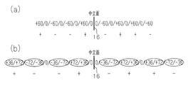
- ⁇ may be 60 °.
- FIG. 1 For a combination of a fiber bundle layer with a fiber orientation angle of + ⁇ and a fiber bundle layer with a fiber orientation angle of ⁇ , ⁇ may be 60 °.
- a laminated fiber bundle layer including a fiber bundle layer having a fiber orientation angle of 0 °, that is, four fiber bundle layers are laminated in increments of 60 °. Four sets of laminated fiber bundle layers thus obtained are shown.
- a fiber bundle layer with a fiber orientation angle of + ⁇ is composed of one pair of a fiber bundle layer with a fiber orientation angle of + 36 ° and a fiber bundle layer with a fiber orientation angle of + 72 °, and the fiber orientation angle is ⁇ .
- the fiber bundle layer may be composed of a pair of two layers of a fiber bundle layer having a fiber orientation angle of ⁇ 36 ° and a fiber bundle layer having a fiber orientation angle of ⁇ 72 °.
- a quasi-isotropic layer is formed by setting one unit of five layers of fiber bundles including a fiber bundle layer having a fiber orientation angle of 0 ° added in 36 ° increments.
- a fiber bundle layer is configured.
- a quasi-isotropic laminated fiber bundle layer having an inversely symmetric structure can be configured by arranging two units on both sides of the neutral plane.
- a fiber bundle layer having a fiber orientation angle of + 36 ° and a fiber bundle layer having a fiber orientation angle of + 72 ° are combined into a fiber bundle layer of + ⁇
- the configuration is the same as that of the invention of claim 1.
- the warp of the fiber-reinforced composite material 11 can be reduced without performing a special manufacturing method. That is, there is no need to manufacture a mold in advance of warping deformation, to correct warping by reheating and compressing after molding, or to form a woven fabric with fibers having different twisting moments.
- -It is not necessary to arrange a fiber bundle layer having a fiber orientation angle of 0 ° as a fiber bundle layer adjacent to the neutral surface 16.
- a fiber bundle layer having a fiber orientation angle of 90 ° may be disposed instead of the fiber bundle layer having a fiber orientation angle of 0 °.
- a fiber bundle layer having a fiber orientation angle of + ⁇ and a fiber bundle layer of ⁇ may be arranged so as to be adjacent to the neutral surface 16.
- the fiber reinforced composite material 11 does not need to have pseudo-isotropic property as a whole.
- the number of fiber bundle layers having a fiber orientation angle of 0 ° is reduced or eliminated, or the number of fiber bundle layers having a fiber orientation angle of 90 ° is set. It may be reduced.
- the number of + ⁇ layers that are fiber bundle layers with a fiber orientation angle of + ⁇ and the number of ⁇ layers that are fiber bundle layers with a fiber orientation angle of ⁇ are the same on one of both sides across the reference plane.
- the stacking order of the fiber bundle layers is inversely symmetric with respect to the reference plane, and the number of other fiber bundle layers arranged between the + ⁇ layer and the ⁇ layer on both sides sandwiching the reference plane is If it is the same, the curvature of the fiber reinforced composite material 11 can be reduced.
- the arrangement position of the fiber bundle layer having a fiber orientation angle of 0 ° and the arrangement position of the fiber bundle layer having a fiber orientation angle of 90 ° may be exchanged.
- fiber bundle layers arranged between the + ⁇ layer and the ⁇ layer on both sides of the reference plane that is, a fiber bundle layer having a fiber orientation angle of 0 ° or a fiber bundle having a fiber orientation angle of 90 °
- the number of layers may be two or more. Further, both fiber bundle layers having a fiber orientation angle of 0 ° or 90 ° may be disposed between the + ⁇ layer and the ⁇ layer.
- a quasi-isotropic fiber reinforced composite material 11 is manufactured using a fiber bundle layer having a fiber orientation angle of 0 ° or 90 ° in addition to a fiber bundle layer having a fiber orientation angle of + 45 ° or ⁇ 45 °.
- fiber bundle layers having a fiber orientation angle of 0 ° or 90 ° are combined with warp groups and weft groups of general plain woven fabrics or twill woven fabrics. May be substituted. If the warp group and the weft group of the plain woven fabric are substituted, the proportion of the reinforcing fibers that are bent at the intersection increases.
- the physical property of the fiber reinforced composite material 11 finally obtained improves when all the fiber bundle layers are composed of unidirectional fabrics.
- a fiber bundle layer having a fiber orientation angle of 0 ° or 90 ° is substituted with a warp group and a weft group of a general plain woven fabric, the man-hour for arranging the fiber bundle layer is reduced.
- a commercially available carbon fiber fabric can be used for the fiber bundle layer, the manufacturing cost can be reduced.
- a laminate fiber bundle layer bonded with stitch yarns arranged in the thickness direction may be used.
- a fiber reinforced composite material having a shape other than a flat plate is produced by the RTM method, after forming the laminated fiber bundle layer into a desired shape outside the mold, the preformed molded body is placed in the mold. Also good.
- the method of manufacturing the fiber reinforced composite material is not limited to the RTM method.
- a fiber bundle arranged in one direction is impregnated with a thermosetting resin to form a plurality of semi-cured prepregs, and a plurality of prepregs are laminated to form a laminated fiber bundle layer, which is placed in a mold.
- the laminated fiber bundle layer may be heated and pressurized.
- the flat skin portion 12 and the reinforcing portion 14 that is integrated on the skin portion 12 and has an inverted T-shaped cross section are manufactured simultaneously. May be. Further, after the skin portion 12 and the reinforced portion 14 are manufactured separately, the reinforced portion 14 may be integrated with the skin portion 12. In this case, an adhesive or a fastener such as a bolt and a nut may be used for fixing the skin portion 12 and the reinforcing portion 14.
- Fiber-reinforced composite materials are not limited to aircraft structural materials, but may be used for other structural materials.
- the thermosetting resin constituting the matrix resin of the fiber reinforced composite material may be an unsaturated polyester resin, a phenol resin, or the like in addition to the epoxy resin.
- an epoxy resin is used, if a carbon fiber is used as the reinforcing fiber, a fiber-reinforced composite material that satisfies the target mechanical properties and heat resistance can be easily produced.
- fiber bundles constituting reinforcing fibers in addition to carbon fibers, high-strength organic fibers such as aramid fibers, poly-p-phenylenebenzobisoxazole fibers, and ultrahigh molecular weight polyethylene fibers, and inorganic fibers such as glass fibers and ceramic fibers May be used.
- high-strength organic fibers such as aramid fibers, poly-p-phenylenebenzobisoxazole fibers, and ultrahigh molecular weight polyethylene fibers
- inorganic fibers such as glass fibers and ceramic fibers May be used.
- the matrix of the fiber reinforced composite material is not limited to the fiber reinforced resin, and may be a material other than the resin.
- a carbon / carbon composite material obtained by firing a fiber reinforced resin having carbon fibers as reinforcing fibers and carbonizing the resin may be used.
Landscapes
- Engineering & Computer Science (AREA)
- Mechanical Engineering (AREA)
- Textile Engineering (AREA)
- Aviation & Aerospace Engineering (AREA)
- Chemical & Material Sciences (AREA)
- Composite Materials (AREA)
- Moulding By Coating Moulds (AREA)
- Laminated Bodies (AREA)
- Reinforced Plastic Materials (AREA)
- Casting Or Compression Moulding Of Plastics Or The Like (AREA)
- Woven Fabrics (AREA)
Abstract
La présente invention porte sur un matériau composite renforcé par des fibres (11), dans lequel matériau une couche de faisceaux de fibres stratifiée est formée par stratification d'une pluralité de couches de faisceaux de fibres constituées par une fibre de renfort, et, de plus, il est réalisé une imprégnation d'une matrice dans la couche de faisceaux de fibres stratifiées. De chaque côté d'une surface neutre (16), le nombre de couches de faisceaux de fibres +θ qui ont un angle d'orientation de fibre de +θ est le même que le nombre de couches de faisceaux de fibres -θ qui ont un angle d'orientation de fibre de -θ. L'ordre de stratification des couches de faisceaux de fibres est inversement symétrique par rapport à une surface standard, et le nombre d'autres couches de faisceaux de fibres disposées entre chacune des couches +θ et -θ des deux côtés vis-à-vis de la surface standard est le même.
Priority Applications (3)
| Application Number | Priority Date | Filing Date | Title |
|---|---|---|---|
| EP12817028.9A EP2737995B1 (fr) | 2011-07-27 | 2012-05-10 | Matériau composite renforcé par des fibres |
| ES12817028T ES2795799T3 (es) | 2011-07-27 | 2012-05-10 | Material de compuesto reforzado con fibra |
| US14/234,314 US9302445B2 (en) | 2011-07-27 | 2012-05-10 | Fiber-reinforced composite material |
Applications Claiming Priority (2)
| Application Number | Priority Date | Filing Date | Title |
|---|---|---|---|
| JP2011164445A JP5617788B2 (ja) | 2011-07-27 | 2011-07-27 | 繊維強化複合材料 |
| JP2011-164445 | 2011-07-27 |
Publications (1)
| Publication Number | Publication Date |
|---|---|
| WO2013014992A1 true WO2013014992A1 (fr) | 2013-01-31 |
Family
ID=47600852
Family Applications (1)
| Application Number | Title | Priority Date | Filing Date |
|---|---|---|---|
| PCT/JP2012/061966 WO2013014992A1 (fr) | 2011-07-27 | 2012-05-10 | Matériau composite renforcé par des fibres |
Country Status (5)
| Country | Link |
|---|---|
| US (1) | US9302445B2 (fr) |
| EP (1) | EP2737995B1 (fr) |
| JP (1) | JP5617788B2 (fr) |
| ES (1) | ES2795799T3 (fr) |
| WO (1) | WO2013014992A1 (fr) |
Families Citing this family (13)
| Publication number | Priority date | Publication date | Assignee | Title |
|---|---|---|---|---|
| US9545757B1 (en) | 2012-02-08 | 2017-01-17 | Textron Innovations, Inc. | Composite lay up and method of forming |
| EP2910365B1 (fr) * | 2014-02-21 | 2017-04-26 | Airbus Operations GmbH | Élément structural composite et caisson de torsion |
| CN104552667B (zh) * | 2014-12-04 | 2017-03-29 | 新誉集团有限公司 | 一种t形梁复合材料热压罐用成型模具 |
| US10005267B1 (en) | 2015-09-22 | 2018-06-26 | Textron Innovations, Inc. | Formation of complex composite structures using laminate templates |
| KR101901333B1 (ko) * | 2016-11-21 | 2018-11-05 | 주식회사 라컴텍 | Cfrp 프리프레그를 이용한 성형품의 제조방법 |
| WO2018170084A1 (fr) | 2017-03-16 | 2018-09-20 | Guerrilla Industries LLC | Structures composites et procédés de formation de structures composites |
| EP3606741B1 (fr) * | 2017-04-04 | 2023-08-09 | The Board of Trustees of the Leland Stanford Junior University | Structures sous-stratifiées composites doubles-doubles et leurs procédés de fabrication et d'utilisation |
| CN109228547B (zh) * | 2018-10-24 | 2021-04-16 | 株洲时代新材料科技股份有限公司 | 增强材料的纤维铺层结构、拉挤型材 |
| CN113021939B (zh) * | 2021-02-09 | 2022-04-22 | 博戈橡胶塑料(株洲)有限公司 | 基于连续纤维与普通纤维的轻量化部件制作方法及制品 |
| US11572124B2 (en) | 2021-03-09 | 2023-02-07 | Guerrilla Industries LLC | Composite structures and methods of forming composite structures |
| US11858249B2 (en) | 2021-03-16 | 2024-01-02 | The Board Of Trustees Of The Leland Stanford Junior University | Stacking sequence combinations for double-double laminate structures |
| KR102300526B1 (ko) * | 2021-04-08 | 2021-09-09 | 국방과학연구소 | 하이브리드 복합 섬유 재료, 제조 방법 및 이를 포함하는 비행체 날개 구조물 |
| US11752707B2 (en) | 2021-05-13 | 2023-09-12 | The Board Of Trustees Of The Leland Stanford Junior University | Octogrid constructions and applications utilizing double-double laminate structures |
Citations (5)
| Publication number | Priority date | Publication date | Assignee | Title |
|---|---|---|---|---|
| JPS6336060U (fr) | 1986-08-26 | 1988-03-08 | ||
| JPH091713A (ja) | 1995-06-20 | 1997-01-07 | Nissan Motor Co Ltd | 繊維強化型積層構造体,円筒形状の繊維強化型積層構造体および曲率を有した繊維強化型積層構造体 |
| JP2004346190A (ja) * | 2003-05-22 | 2004-12-09 | Mitsubishi Rayon Co Ltd | プリプレグ及び繊維強化樹脂複合材料 |
| WO2008038429A1 (fr) * | 2006-09-28 | 2008-04-03 | Toray Industries, Inc. | Plastique renforcé par fibres et son procédé de production |
| JP2009191186A (ja) * | 2008-02-15 | 2009-08-27 | Toray Ind Inc | 一体化構造体 |
Family Cites Families (6)
| Publication number | Priority date | Publication date | Assignee | Title |
|---|---|---|---|---|
| JPS6336060Y2 (fr) | 1985-10-31 | 1988-09-26 | ||
| JP2002307590A (ja) | 2001-04-10 | 2002-10-23 | National Aerospace Laboratory Of Japan | 積層複合材料 |
| US20030175520A1 (en) | 2002-03-13 | 2003-09-18 | Grutta James T. | Formed composite structural members and methods and apparatus for making the same |
| JP2008037258A (ja) | 2006-08-07 | 2008-02-21 | Toray Ind Inc | 自転車用クランク |
| CN101532253B (zh) | 2008-03-12 | 2012-09-05 | 比亚迪股份有限公司 | 碳纤维复合材料制品及其制造方法 |
| US8263205B2 (en) * | 2009-09-17 | 2012-09-11 | Hexcel Corporation | Method of molding complex composite parts using pre-plied multi-directional continuous fiber laminate |
-
2011
- 2011-07-27 JP JP2011164445A patent/JP5617788B2/ja not_active Expired - Fee Related
-
2012
- 2012-05-10 WO PCT/JP2012/061966 patent/WO2013014992A1/fr active Application Filing
- 2012-05-10 US US14/234,314 patent/US9302445B2/en not_active Expired - Fee Related
- 2012-05-10 ES ES12817028T patent/ES2795799T3/es active Active
- 2012-05-10 EP EP12817028.9A patent/EP2737995B1/fr active Active
Patent Citations (5)
| Publication number | Priority date | Publication date | Assignee | Title |
|---|---|---|---|---|
| JPS6336060U (fr) | 1986-08-26 | 1988-03-08 | ||
| JPH091713A (ja) | 1995-06-20 | 1997-01-07 | Nissan Motor Co Ltd | 繊維強化型積層構造体,円筒形状の繊維強化型積層構造体および曲率を有した繊維強化型積層構造体 |
| JP2004346190A (ja) * | 2003-05-22 | 2004-12-09 | Mitsubishi Rayon Co Ltd | プリプレグ及び繊維強化樹脂複合材料 |
| WO2008038429A1 (fr) * | 2006-09-28 | 2008-04-03 | Toray Industries, Inc. | Plastique renforcé par fibres et son procédé de production |
| JP2009191186A (ja) * | 2008-02-15 | 2009-08-27 | Toray Ind Inc | 一体化構造体 |
Non-Patent Citations (1)
| Title |
|---|
| See also references of EP2737995A4 |
Also Published As
| Publication number | Publication date |
|---|---|
| EP2737995B1 (fr) | 2020-05-06 |
| EP2737995A4 (fr) | 2015-04-01 |
| JP5617788B2 (ja) | 2014-11-05 |
| ES2795799T3 (es) | 2020-11-24 |
| US9302445B2 (en) | 2016-04-05 |
| US20140170371A1 (en) | 2014-06-19 |
| JP2013028019A (ja) | 2013-02-07 |
| EP2737995A1 (fr) | 2014-06-04 |
Similar Documents
| Publication | Publication Date | Title |
|---|---|---|
| WO2013014992A1 (fr) | Matériau composite renforcé par des fibres | |
| AU2005289392B2 (en) | Thin ply laminates | |
| JP6207241B2 (ja) | 複合積層板内の最適化されたクロスプライ配向 | |
| EP3018293A1 (fr) | Composant en matière composite avec noyau renforcé en fibre | |
| WO2004071761A1 (fr) | Lamine de plaques metalliques a ame de plastique renforcee de fibres croisees de differents materiaux | |
| JP7249404B2 (ja) | 複合材料製パネル構造体およびその製造方法 | |
| US10697094B2 (en) | Fiber structure and fiber reinforced composite material | |
| US10947647B2 (en) | Fabric for fiber reinforced composite material and fiber reinforced composite material | |
| JP2021025164A (ja) | 繊維構造体及び繊維強化複合材 | |
| EP3712309A1 (fr) | Structure de fibres, matériau composite renforcé de fibres et procédé de fabrication associé | |
| JP7287162B2 (ja) | 繊維構造体及び繊維強化複合材 | |
| EP3388215B1 (fr) | Panneau sandwich, procédé de production de préimprégné unidirectionnel, et procédé de production de panneau sandwich | |
| KR20190031908A (ko) | 섬유 강화 플라스틱 시트와 이를 포함하는 적층체 | |
| JP5644755B2 (ja) | 織物基材及び繊維強化複合材料 | |
| JP2017025216A (ja) | 繊維強化複合材料 | |
| US20220396049A1 (en) | Core material and structure | |
| JP3535024B2 (ja) | バイセクトタイプの繊維強化プラスチック製のハニカムコアの製造方法 | |
| JP6528651B2 (ja) | 繊維構造体 | |
| JP6832536B2 (ja) | プリプレグ積層体及びその製造方法 | |
| WO2014034606A1 (fr) | Structure en fibre tridimensionnelle, préimprégné utilisant celle-ci et procédé de fabrication d'une structure en fibre tridimensionnelle | |
| WO2013191232A1 (fr) | Matériau composite à fibres de renforcement et son procédé de production | |
| JP2015033819A (ja) | 三次元繊維強化複合材 | |
| JPS62270633A (ja) | 複合エレメント |
Legal Events
| Date | Code | Title | Description |
|---|---|---|---|
| 121 | Ep: the epo has been informed by wipo that ep was designated in this application |
Ref document number: 12817028 Country of ref document: EP Kind code of ref document: A1 |
|
| WWE | Wipo information: entry into national phase |
Ref document number: 14234314 Country of ref document: US |
|
| WWE | Wipo information: entry into national phase |
Ref document number: 2012817028 Country of ref document: EP |
|
| NENP | Non-entry into the national phase |
Ref country code: DE |