WO2013014944A1 - 生体試料測定装置及び生体試料測定センサ収納装置 - Google Patents
生体試料測定装置及び生体試料測定センサ収納装置 Download PDFInfo
- Publication number
- WO2013014944A1 WO2013014944A1 PCT/JP2012/004814 JP2012004814W WO2013014944A1 WO 2013014944 A1 WO2013014944 A1 WO 2013014944A1 JP 2012004814 W JP2012004814 W JP 2012004814W WO 2013014944 A1 WO2013014944 A1 WO 2013014944A1
- Authority
- WO
- WIPO (PCT)
- Prior art keywords
- biological sample
- unit
- sensor
- measurement
- lid
- Prior art date
Links
Images


Classifications
-
- G—PHYSICS
- G08—SIGNALLING
- G08B—SIGNALLING OR CALLING SYSTEMS; ORDER TELEGRAPHS; ALARM SYSTEMS
- G08B21/00—Alarms responsive to a single specified undesired or abnormal condition and not otherwise provided for
- G08B21/18—Status alarms
-
- G—PHYSICS
- G01—MEASURING; TESTING
- G01N—INVESTIGATING OR ANALYSING MATERIALS BY DETERMINING THEIR CHEMICAL OR PHYSICAL PROPERTIES
- G01N27/00—Investigating or analysing materials by the use of electric, electrochemical, or magnetic means
- G01N27/26—Investigating or analysing materials by the use of electric, electrochemical, or magnetic means by investigating electrochemical variables; by using electrolysis or electrophoresis
- G01N27/28—Electrolytic cell components
-
- G—PHYSICS
- G01—MEASURING; TESTING
- G01N—INVESTIGATING OR ANALYSING MATERIALS BY DETERMINING THEIR CHEMICAL OR PHYSICAL PROPERTIES
- G01N27/00—Investigating or analysing materials by the use of electric, electrochemical, or magnetic means
- G01N27/26—Investigating or analysing materials by the use of electric, electrochemical, or magnetic means by investigating electrochemical variables; by using electrolysis or electrophoresis
- G01N27/416—Systems
-
- G—PHYSICS
- G01—MEASURING; TESTING
- G01N—INVESTIGATING OR ANALYSING MATERIALS BY DETERMINING THEIR CHEMICAL OR PHYSICAL PROPERTIES
- G01N33/00—Investigating or analysing materials by specific methods not covered by groups G01N1/00 - G01N31/00
- G01N33/48—Biological material, e.g. blood, urine; Haemocytometers
- G01N33/483—Physical analysis of biological material
- G01N33/487—Physical analysis of biological material of liquid biological material
- G01N33/4875—Details of handling test elements, e.g. dispensing or storage, not specific to a particular test method
- G01N33/48778—Containers specially adapted therefor, e.g. for dry storage
Definitions
- the present invention relates to a biological sample measurement device and a biological sample measurement sensor storage device that store a biological sample measurement sensor.
- a biological sample measuring device including a sensor bottle that houses a biological sample measuring sensor and a biological sample measuring device to which the sensor bottle is attached is known (for example, Patent Document 1 and Patent Document 2).
- Patent Document 1 and Patent Document 2 the sensor bottle and the biological sample measuring device are integrated, and the biological sample measuring sensor and the biological sample measuring device can be easily carried and managed easily.
- the lid of the sensor bottle is opened and the biological sample measuring sensor housed in the sensor bottle is taken out.
- the extracted biological sample measurement sensor is attached to the sensor attachment portion of the biological sample measurement device.
- the blood exuded from the skin punctured by a separate puncture device is spotted on the biological sample measurement sensor mounted on the sensor mounting portion. Then, the biological sample measurement device measures the blood glucose level.
- the performance of the biological sample measurement sensor deteriorates due to the influence of humidity or temperature. For this reason, the user needs to close the lid of the sensor bottle immediately after taking out the biological sample measurement sensor.
- Patent Document 1 and Patent Document 2 after opening the lid to take out the biological sample measurement sensor, if the user forgets to close the lid, or if some impact is applied to the sensor bottle, the lid is removed. If opened, the user may not be aware that the lid is open. Therefore, there is a problem that the performance of the biological sample measurement sensor stored in the sensor bottle deteriorates.
- An object of the present invention is to provide a biological sample capable of suppressing deterioration of the performance of the biological sample measurement sensor by appropriately notifying the user that the cover of the storage unit that stores the biological sample measurement sensor is open. It is to provide a measurement device and a biological sample measurement sensor storage device.
- a biological sample measurement device is a biological sample measurement device to which a sensor bottle having a cylindrical storage portion that can store a biological sample measurement sensor and a lid that opens and closes the opening is mounted.
- a biological sample measurement sensor storage device is a biological sample measurement sensor storage to which a sensor bottle having a cylindrical storage portion that can store a biological sample measurement sensor and a lid that opens and closes the opening is mounted.
- a detection unit that detects that the lid is open; and a notification unit that notifies error information indicating that the lid is open based on a detection result of the detection unit.
- the present invention it is possible to suppress the deterioration of the performance of the biological sample measurement sensor by appropriately notifying the user that the lid of the sensor bottle housing the biological sample measurement sensor is open.
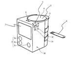
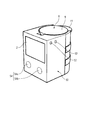
- FIG. 1 is a front perspective view of a biological sample measurement device equipped with a sensor bottle in Embodiment 1 of the present invention.
- 1 is a rear perspective view of a biological sample measurement device equipped with a sensor bottle with a lid closed according to Embodiment 1 of the present invention.
- 1 is a rear perspective view of a biological sample measurement device equipped with a sensor bottle with a lid opened in Embodiment 1 of the present invention.
- 1 is a rear perspective view of a biological sample measurement device and a sensor bottle before mounting the sensor bottle in Embodiment 1 of the present invention.
- the perspective view of the sensor bottle in Embodiment 1 of this invention is a block diagram showing a configuration of a biological sample measurement device according to Embodiment 1 of the present invention.
- the flowchart which shows the acquisition method of the biometric information in Embodiment 1 of this invention
- the figure which shows an example of the error display in Embodiment 1 of this invention
- Front perspective view of a biological sample measurement device equipped with a sensor bottle in Embodiment 2 of the present invention The block diagram which shows the structure of the biological sample measuring device which concerns on Embodiment 2 of this invention.
- FIG. 15 (a) and FIG.15 (b) The front perspective view of the biological sample measurement sensor storage apparatus which attached the sensor bottle in Embodiment 3 of this invention.
- the rear perspective view of the biological sample measurement sensor storage apparatus which attached the sensor bottle in Embodiment 3 of this invention The block diagram which shows the structure of the biological sample measurement sensor storage apparatus which concerns on Embodiment 3 of this invention.
- the flowchart which shows the display method in Embodiment 3 of this invention The flowchart which shows the modification of the display method in Embodiment 3 of this invention
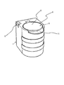
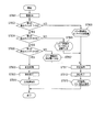
- the biological sample measuring apparatus 1 includes a display unit 2, an operation unit 3, a sensor mounting unit 5, a bottle mounting unit 6, a recess 12, a first detection switch 13, and a second detection switch 17 (bottle detection). Switch) and a third detection switch 18 (bottle detection switch).
- the biological sample measuring device 1 has a rectangular parallelepiped shape.
- the biological sample measurement device 1 is equipped with a biological sample measurement sensor 4, and acquires biological information from the attached biological sample measurement sensor 4.
- the biological information is, for example, a blood glucose level.
- the display unit 2 serving as a notification unit is provided on the front side of the biological sample measuring device 1.
- the display unit 2 displays the measurement result of the biological information, error information indicating that the lid 9 is open, and the mounting state of the sensor bottle 8.
- the display unit 2 can display as follows. That is, the display unit 2 can display the measurement result of the biological information and the error information together on one screen.
- the display unit 2 can display the measurement result of the biological information and then display error information.
- the display unit 2 can display error information and then display a measurement result of biological information.
- the display unit 2 can alternately display the measurement result of biometric information and error information. Alternatively, the display unit 2 can display error information at an arbitrary timing.
- the display unit 2 has, for example, a liquid crystal display or an organic EL display.
- the operation unit 3 includes a first operation unit 3a, a second operation unit 3b, and a third operation unit 3c.
- the operation unit 3 is operated when switching the display of the display unit 2 and starting measurement for acquiring biological information.
- the number of operation units 3 is not limited to three.
- the sensor mounting portion 5 is provided at the upper end of the side surface of the biological sample measuring device 1.
- a biological sample measurement sensor 4 is inserted and attached to the sensor attachment unit 5 in order to acquire biological information.
- the sensor mounting portion 5 is provided with a plurality of connectors (not shown) that are connected to the biological sample measurement sensor 4.
- the upper surface opening 7 is formed at the upper end of the bottle mounting portion 6.
- the bottle mounting part 6 has a bottomed cylindrical shape.
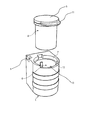
- a sensor bottle 8 is stored in the bottle mounting portion 6. The sensor bottle 8 is inserted from the upper surface opening 7 and attached to the bottle attaching part 6.
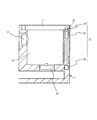
- the recess 12 is provided at the upper end on the back side of the biological sample measuring device 1.
- the recess 12 is provided with a first detection switch 13 (see FIG. 5).
- the first detection switch 13 that is an open / close detection unit includes an actuator unit 14, a spring 15, and a switch 16 (see FIG. 4).
- the actuator unit 14 is disposed in the recess 12.
- the spring 15 is disposed below the actuator unit 14.
- the switch 16 is disposed below the spring 15. In the first detection switch 13, when the actuator unit 14 is pressed by the lid 9, the actuator unit 14 and the spring 15 move downward to press the switch 16. When the first detection switch 13 is further pressed from the above state, only the spring 15 is compressed so that the switch 16 is not overloaded.
- the first detection switch 13 detects opening / closing of the lid 9.
- the second detection switch 17 that is a mounting detection unit is provided on the inner side surface of the bottle mounting unit 6 or on the inner bottom surface of the bottle mounting unit 6, but may be provided on both of them ( (See FIG. 4).
- the second detection switch 17 detects whether or not the sensor bottle 8 is attached to the bottle attachment portion 6.
- the third detection switch 18 detects whether or not the sensor bottle 8 is correctly attached to the bottle attachment portion 6.
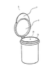
- the sensor bottle 8 is mainly composed of a lid 9, a lid opening / closing part 11, and a storage part 26 as shown in FIG.
- the sensor bottle 8 has a cylindrical shape (see FIGS. 5 and 6) and is attached to the biological sample measuring apparatus 1.
- the lid 9 is provided so as to be openable and closable with respect to the upper surface opening 25 at the upper end of the storage portion 26.
- the lid 9 closes the upper surface opening 25 in the closed state (the state shown in FIGS. 1 and 2). That is, the upper surface opening 25 is opened and closed by the lid 9.
- the lid 9 closes the upper surface opening 25 except when necessary in order to enhance the drying action of the desiccant stored in the storage unit 26.
- the upper surface opening 25 is provided for taking out the biological sample measurement sensor 4 stored in the storage unit 26.
- the lid opening / closing part 11 has a bowl shape and is provided on the lid 9.
- the lid opening / closing section 11 is provided at a position facing the recess 12 when the sensor bottle 8 is mounted on the bottle mounting section 6 with the lid 9 closed (see FIG. 3 and the like). Thereby, the lid opening / closing part 11 presses the actuator part 14 of the first detection switch 13 downward in a state where the lid 9 is closed.
- the storage unit 26 has a cylindrical shape with one end opening.
- the storage unit 26 can store the biological sample measurement sensor 4.
- An upper surface opening 25 for taking out the biological sample measurement sensor 4 is formed in the storage unit 26.
- the storage unit 26 stores a desiccant (not shown).
- the biological sample measurement sensor 4 is mainly composed of an electrode part 40 and a spotting part 41.
- the biological sample measurement sensor 4 is housed in the sensor bottle 8 so that the electrode part 40 side is downward and the spotting part 41 side is upward.
- the electrode part 40 is located in the sensor attachment part 5 when the biological sample measurement sensor 4 is attached to the sensor attachment part 5.
- the electrode unit 40 detects that a biological sample has been spotted on the spotting unit 41.
- the electrode unit 40 comes into contact with a plurality of connectors (not shown) provided in the sensor mounting unit 5 when the biological sample measurement sensor 4 is mounted on the sensor mounting unit 5. And the electrode part 40 is electrically connected with the measurement part 21 (refer FIG. 8) in the biological sample measuring device 1 etc. via these connectors. Thereby, the biological sample measuring device 1 detects the sensor mounting detection of the biological sample measuring sensor 4, the model determination of the biological sample measuring sensor 4, the spotting detection of the biological sample, and the measurement of the biological sample substrate concentration (for example, blood glucose level measurement). Etc.
- the spotting unit 41 is located outside when the biological sample measurement sensor 4 is mounted on the sensor mounting unit 5.
- the spotting unit 41 is spotted with a biological sample.
- the biological sample is blood, for example.
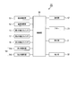
- the biological sample measurement device 1 includes a display unit 2, a first operation unit 3 a, a second operation unit 3 b, a third operation unit 3 c, a first detection switch 13, and a second detection switch 17. And a third detection switch 18, a control unit 19, a sensor insertion detection unit 20, a measurement unit 21, a memory 22, a buzzer 23, and a sensor connection unit 24.
- a display unit 2 a first operation unit 3 a, a second operation unit 3 b, a third operation unit 3 c, a first detection switch 13, and a second detection switch 17.
- a third detection switch 18 a control unit 19, a sensor insertion detection unit 20, a measurement unit 21, a memory 22, a buzzer 23, and a sensor connection unit 24.
- FIG. 8 the same components as those in FIGS. 1 to 7 are denoted by the same reference numerals, and the description thereof is omitted.
- the control unit 19 controls the display unit 2, the first operation unit 3 a, the second operation unit 3 b, the third operation unit 3 c, and the sensor connection unit 24.
- the control unit 19 acquires the measurement result measured by the measurement unit 21 and stores it in the memory 22.
- the control unit 19 controls the buzzer 23 so as to notify the completion of the measurement.
- the control unit 19 performs control for displaying the measurement result in the measurement unit 21 on the display unit 2.
- the control unit 19 acquires a detection result in the first detection switch 13, the second detection switch 17, or the third detection switch 18, and displays error information or a mounting state of the sensor bottle 8 based on the acquired detection result. Control for displaying on the unit 2 is performed.
- the sensor insertion detection unit 20 detects that the biological sample measurement sensor 4 is connected to the sensor connection unit 24.
- the sensor insertion detection unit 20 detects whether or not the electrode unit 40 of the biological sample measurement sensor 4 is connected to the sensor connection unit 24 by an electrical method.
- the measurement unit 21 measures biological information using the biological sample measurement sensor 4. Specifically, the measurement unit 21 starts measurement for acquiring biological information when the biological sample measurement sensor 4 acquires a detection result connected to the sensor connection unit 24 from the sensor connection unit 24. The measurement unit 21 outputs the measurement result to the control unit 19.
- the memory 22 stores the measurement result input from the control unit 19.
- the buzzer 23 performs notification to notify the completion of measurement under the control of the control unit 19.
- the sensor connection unit 24 has a sensor insertion detection unit 20.
- the sensor connection unit 24 outputs a detection result to the measurement unit 21 when the sensor insertion detection unit 20 detects that the biological sample measurement sensor 4 is connected.
- the sensor connection portion 24 is provided in the sensor mounting portion 5 described above.
- the sensor connection unit 24 has a plurality of connectors (not shown) that electrically connect the biological sample measurement sensor 4 and the measurement unit 21.
- a user who wants to acquire biometric information opens the lid 9 of the sensor bottle 8. At this time, the first detection switch 13 is OFF.
- the user takes out the biological sample measurement sensor 4 from the storage part 26 of the sensor bottle 8 and inserts the taken-out biological sample measurement sensor 4 into the sensor mounting part 5.
- the electrode portion 40 side of the biological sample measurement sensor 4 is inserted into the sensor mounting portion 5.
- the sensor insertion detection unit 20 detects the insertion of the biological sample measurement sensor 4.
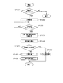
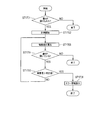
- step ST801 the power source of the biological sample measuring device 1 is turned on.
- control unit 19 confirms the state of the second detection switch 17 and determines whether or not the second detection switch 17 is ON (step ST802).
- control unit 19 determines that the second detection switch 17 is not turned on (step ST802: NO)
- the control unit 19 displays on the display unit 2 that the sensor bottle 8 is not mounted on the bottle mounting unit 6. Control is performed (step ST803).
- step ST802 When it is determined that the second detection switch 17 is ON (step ST802: YES), the control unit 19 confirms the state of the third detection switch 18, and the third detection switch 18 is turned ON. It is determined whether or not (step ST804).
- step ST804 NO
- the control unit 19 indicates that the sensor bottle 8 is not correctly attached to the bottle attaching unit 6 (“sensor bottle not attached” “Complete”) is displayed on the display unit 2 (step ST805).
- step ST804 When it is determined that the third detection switch 18 is turned on (step ST804: YES), the control unit 19 confirms the state of the first detection switch 13, and the first detection switch 13 is turned on. Is determined (step ST806).
- step ST806 NO
- the control unit 19 displays error information indicating that the lid 9 is open on the display unit 2.
- step ST806 determines that the first detection switch 13 is ON (step ST806: YES)
- the measurement unit 21 performs measurement processing without performing control for displaying error information. It performs (step ST808).
- the user places a biological sample on the spotting part 41 of the biological sample measurement sensor 4 and starts measurement of the biological sample.
- the measurement unit 21 detects that the biological sample is spotted via the electrode unit 40 of the biological sample measurement sensor 4. Thereafter, the measurement unit 21 starts measurement.
- the measurement unit 21 completes the measurement after a predetermined time (for example, about 3 to 15 seconds) has elapsed since the measurement was started (step ST809).
- a predetermined time for example, about 3 to 15 seconds
- the display part 2 displays only the measurement result measured by the said measurement part 21 as biometric information according to control of the control part 19 (step ST810).
- the measurement unit 21 can perform a measurement process even if the first detection switch 13 and the second detection switch 17 or 18 are not ON (step ST811). That is, the user can spot a biological sample on the spotting portion 41 of the biological sample measurement sensor 4 and start measurement of the biological sample. At this time, the measurement unit 21 detects that the biological sample is spotted via the electrode unit 40 of the biological sample measurement sensor 4. Thereafter, the measurement unit 21 starts measurement.
- the measurement unit 21 completes the measurement after a predetermined time (for example, about 3 to 15 seconds) has elapsed since the measurement was started (step ST812).
- a predetermined time for example, about 3 to 15 seconds
- the display part 2 displays a measurement result as biometric information according to control of the control part 19, and displays biometric information and error information according to control of the control part 19 of step ST803, step ST805, or step ST807 ( Step ST813).
- the measurement result and the error information may be displayed at the same time, may be displayed alternately in large characters, or may be displayed at the same time and only the error information blinks.
- the display unit 2 displays the text “ Caution bottle lid is open” as error information, for example, as shown in FIG.
- Embodiment 1 it is possible to prevent deterioration of the performance of the biological sample measurement sensor by appropriately notifying the user that the cover of the storage unit that stores the biological sample measurement sensor is open. .
- the biological sample measurement apparatus 1 may be provided with a communication unit, and error information may be transmitted from the communication unit to other devices such as a communication terminal device. At this time, error information may be transmitted when a request is received from another device. In this case, a user who has another device at a location away from the biological sample measurement device 1 can recognize that the lid is open.
- the communication unit (equivalent to the communication unit 34 in FIG. 12 to be described later) of the biological sample measurement device 1 in the present embodiment is connected to the mobile phone or smartphone owned by the user, and the open / closed state of the sensor bottle 8. And notify. Thereby, after confirming the received notification, the user can take measures such as quickly closing the lid 9 of the sensor bottle 8.
- the user switches the “bottle relation detection function”, which is one of the function selections in the setting mode, using the operation unit 3 (switches ON / OFF).
- the biological sample measuring device 1 is used as a general measuring device having only a normal measuring function.
- FIG. 11 is added with a temperature measurement unit 31 and a humidity measurement unit 32 as compared with the biological sample measurement device 1 according to the first embodiment shown in FIG.
- parts having the same configurations as those in FIG. 1 in the above-described first embodiment are given the same reference numerals, and descriptions thereof are omitted.
- the biological sample measuring device 30 includes a display unit 2, an operation unit 3, a sensor mounting unit 5, a bottle mounting unit 6, a recess 12, a first detection switch 13, a second detection switch 17, and a first detection switch 17. 3 detection switch 18, temperature measurement unit 31, and humidity measurement unit 32.
- the concave portion 12, the first detection switch 13, the second detection switch 17, and the third detection switch 18 are not shown in FIG. 11, but have the same configuration as FIG. .
- the temperature measuring unit 31 measures the external temperature around the biological sample measuring device 30.
- the temperature measuring unit 31 is provided in the vicinity of the sensor mounting unit 5.
- the humidity measuring unit 32 measures the external humidity around the biological sample measuring device 30. Similarly to the temperature measurement unit 31, the humidity measurement unit 32 is also provided in the vicinity of the sensor mounting unit 5.
- biological sample measuring apparatus 30 shown in FIG. 12 includes temperature measuring unit 31, humidity measuring unit 32, clock unit 33, and communication unit. 34 and a bottle reading unit 36 are added, and a control unit 35 is provided instead of the control unit 19.
- FIG. 12 parts having the same configuration as in FIG.
- the biological sample measurement device 30 includes a display unit 2, a first operation unit 3 a, a second operation unit 3 b, a third operation unit 3 c, a first detection switch 13, and a second detection switch 17.
- FIG. 12 the same components as those in FIG. 11 are denoted by the same reference numerals, and the description thereof is omitted.
- the timepiece unit 33 When the first detection switch 13 detects that the lid 9 of the sensor bottle 8 is opened, the timepiece unit 33 describes the time during which the lid 9 of the sensor bottle 8 is open (hereinafter referred to as “opening time”). ).
- the clock unit 33 detects that the lid 9 of the sensor bottle 8 is closed by the first detection switch 13
- information on the measured opening time (the time when the lid 9 was open until then) (hereinafter, (Described as “opening time information”) is output to the control unit 35.
- the control unit 35 stores the opening time information input from the clock unit 33 in the memory 22.
- the control unit 35 calculates the cumulative open time, and stores (updates) the cumulative open time information in the memory 22. Thereafter, the clock unit 33 resets the measured opening time under the control of the control unit 35.
- the communication unit 34 transmits various types of information to other devices under the control of the control unit 35. At this time, the communication unit 34 may transmit various types of information when receiving a request from another device.
- the various types of information include opening time information, accumulated opening time information, temperature information measured by the temperature measuring unit 31, humidity information measured by the humidity measuring unit 32, and the like.
- the opening time information is periodically transmitted regardless of whether the opening time is equal to or longer than the predetermined time or whether the opening time is equal to or longer than the predetermined time.
- another device that is a transmission destination of various types of information is a communication terminal device such as a personal computer, a mobile phone, or a smartphone.
- a user who has another device capable of communicating with the biological sample measuring device 30 at a place away from the biological sample measuring device 30 can detect the lid 9 from the information received from the biological sample measuring device 30. You can recognize that it is open.
- the communication unit 34 of the biological sample measurement device 30 for a personal computer, a mobile phone, or a smartphone owned by the user, together with the measurement result, the open / closed state of the lid 9 of the sensor bottle 8 and the open time information Notify the cumulative opening time information or alarm information.
- the user can take measures such as closing the lid 9 of the sensor bottle 8 quickly after confirming the notification.
- the control unit 35 controls the display unit 2, the first operation unit 3 a, the second operation unit 3 b, the third operation unit 3 c, and the sensor connection unit 24.
- the control unit 35 controls the clock unit 33 to start measuring time. Further, the control unit 35 performs control to stop the time measurement in the clock unit 33 when the detection result indicating that the lid 9 is closed is acquired from the first detection switch 13. Thereby, the control unit 35 can cause the clock unit 33 to measure the opening time.
- the control unit 35 determines the exposure value based on the measurement result of the temperature acquired from the temperature measurement unit 31, the measurement result of the humidity acquired from the humidity measurement unit 32, and the measurement result of the open time acquired from the clock unit 33. calculate.
- the control unit 35 controls the display unit 2 to perform error display when the calculated exposure value is equal to or greater than a predetermined value.
- the control unit 35 performs control to reset the clock unit 33 after controlling the display unit 2 so as to display an error or when detecting that a new sensor bottle 8 is mounted.
- the exposure value is a parameter indicating the influence of the external environment on the biological sample measurement sensor 4.
- the description is abbreviate
- the new sensor bottle 8 is attached by detecting ON / OFF of the second detection switch 17 and the third detection switch 18 which are the attachment detection units.
- the bottle reading unit 36 determines the sensor bottle 8 attached to the bottle attaching unit 6 based on the individual number. The determination result is output to the control unit 35. Thereby, the biological sample measuring device 30 can detect the mounting of a new sensor bottle 8.
- An example of the bottle reading unit 36 is a BCR (barcode reader).
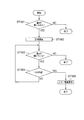
- control unit 35 determines whether or not the lid 9 of the sensor bottle 8 has been opened by the first detection switch 13 which is an open / close detection unit (step ST1201).
- step ST1201: NO the control unit 35 determines that it is not necessary to measure the biological sample, and ends the process.
- step ST1201 when it is determined by the control unit 35 that the lid 9 has been opened (step ST1201: YES), the clock unit 33 starts measuring the opening time (step ST1202).
- control unit 35 determines whether the sensor insertion detection unit 20 detects that the biological sample measurement sensor 4 has been inserted (step ST1203).
- step ST1203 NO
- the control unit 35 repeats the process of step ST1203 to thereby repeat the biological sample. Wait for the insertion of the measurement sensor 4.
- control unit 35 obtains temperature information from the temperature measurement unit 31 and humidity measurement.
- the humidity information is acquired from the unit 32, and the open time information is acquired from the clock unit 33 (step ST1204).
- control unit 35 calculates an exposure value based on the acquired information (step ST1205).
- Control unit 35 determines whether or not the calculated exposure value is greater than a predetermined determination value (step ST1206).
- control unit 35 When it is determined that the exposure value is equal to or less than the predetermined determination value (step ST1206: NO), control unit 35 performs a measurement process such as a substrate concentration of the biological sample (step ST1207). Then, when the measurement process is completed, the control unit 35 performs control to display the measurement result on the display unit 2 as biological information (step ST1208), and ends the process.
- a measurement process such as a substrate concentration of the biological sample
- step ST1206 when it is determined that the exposure value is larger than the predetermined determination value (step ST1206: YES), the control unit 35 performs control to display error information on the display unit 2.
- the display part 2 displays error information according to control of the control part 35 (step ST1209), and complete
- the display unit 2 can display error information as in the first embodiment.
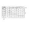
- the vertical axis 141 in FIG. 14 indicates the range of the temperature T.
- the horizontal axis 142 in FIG. 14 indicates the range of the humidity S.
- the control unit 35 Based on the temperature information measured by the temperature measurement unit 31 and the humidity information measured by the humidity measurement unit 32, the control unit 35 obtains the corresponding exposure coefficient 143. And the control part 35 calculates
- the biological sample measurement sensor 4 is more affected by the humidity S than the temperature T. Therefore, when the humidity S is 10% or less (humidity S ⁇ 10%) and the humidity S is greater than 70% (70% ⁇ humidity S), the exposure coefficient is the same for the same temperature range. There is a difference of 5 times. On the other hand, when the temperature T is 0 ° C. or more and less than 10 ° C. (0 ° C. ⁇ temperature T ⁇ 10 ° C.) and the temperature T is higher than 40 ° C. (40 ° C. ⁇ temperature T), In the same humidity range, there is a double difference.
- the exposure value is obtained by calculating the exposure coefficient shown in FIG. 14 and the above opening time, the longer the opening time, the higher the exposure value. Therefore, the exposure value represents that the longer the open time, the greater the influence on the biological sample measurement sensor 4.
- the exposure coefficient is set every 10 ° C. for temperature T and every 20% for humidity S.
- the exposure coefficient is not limited to this, and temperature T is set every 1-10 ° C. and For the humidity S, an exposure coefficient can be set every 2 to 20%.
- the exposure value is calculated using the opening time, temperature, and humidity, and it is notified that the lid 9 of the sensor bottle 8 is open based on the calculated exposure value. From this, according to this Embodiment, in addition to the effect of the said Embodiment 1, the degradation of the performance of a biological sample measurement sensor can be prevented according to the environment which uses a biological sample measurement sensor.
- the biological sample measurement is performed by transmitting the open / close state of the lid 9 of the sensor bottle 8, temperature information, humidity information, open time information, accumulated open time information, alarm information, or the like from the communication unit.
- a user who owns the information transmission destination device at a location away from the apparatus can recognize that the lid is open.
- the user can take measures such as closing the lid 9 of the sensor bottle 8 quickly after confirmation. It becomes.
- a warning may be issued when a state in which the temperature measured by the temperature measuring unit 31 is equal to or higher than the threshold value continues for a predetermined time.
- step ST1205 of FIG. 13 described above the predetermined cumulative determination value is compared with the cumulative exposure value.
- the controller 35 assumes that the lid 9 of the sensor bottle 8 repeats opening and closing, and has shifted from the open state to the closed state by the first detection switch 13 ("open” ⁇ "closed”). ) Is detected, the exposure values determined by the temperature, humidity and open time at that time are accumulated.
- FIG. 15 (a) shows an example of accumulating exposure values, where the X-axis shows time t and the Y-axis shows the exposure coefficient Exk.
- each of Ex1 to Ex5 shows the exposure value when the lid 9 is in the “open” state.
- the control unit 35 may calculate the periodic exposure value periodically (for example, every hour) using the temperature measured by the temperature measurement unit 31 and the humidity measured by the humidity measurement unit 32. Good. And the control part 35 may use the sum total of a regular exposure value as an exposure value, and may compare it with a predetermined determination value. Thereby, the biological sample measuring device 30 can obtain an appropriate exposure value corresponding to a change in the surrounding environment.
- FIG. 15 (b) is a diagram showing the above-mentioned regular exposure values.
- FIG. 15B is an enlarged view of the exposure value Ex5 portion of FIG.
- the temperature measuring unit 31 Since the temperature T shown by the alternate long and short dash line in FIG. 15B is changing while the lid 9 is open (the change in the humidity S is omitted), the temperature measuring unit 31 is kept at a certain time (for example, 1 The temperature T is measured every time), and the humidity measuring unit 32 measures the humidity S every fixed time (for example, 1 hour). Then, the control unit 35 obtains the periodic exposure values Ex-p1 to Ex-p4 using the temperature T and the humidity S measured at regular intervals, and determines the sum of the obtained periodic exposure values as a single exposure value (this In the example, Ex5).
- the detection functions of the first detection switch 13 that is an open / close detection unit, the second detection switch 17 that is a mounting detection unit, and the third detection switch 18 are turned off. Can be.
- the user switches the “bottle relation detection function”, which is one of function selections in the setting mode, from ON to OFF (that is, from “valid” to “invalid”) by the operation unit 3. .
- the biological sample measuring device 30 is used as a general measuring device having only a normal measuring function.
- a mechanical configuration of the biological sample measurement sensor storage device 50 according to the third embodiment of the present invention will be described with reference to FIGS. 16 and 17. 16 and 17, the sensor bottle 8 is also shown together with the biological sample measurement sensor storage device 50.
- the biological sample measurement sensor storage device 50 includes a display unit 2, a bottle mounting unit 6, a recess 12, a first detection switch 13, a second detection switch 17, a third detection switch 18, and a temperature measurement.
- the unit 52, the humidity measurement unit 53, and the operation unit 54 are mainly configured.
- the structure of the display part 2, the bottle mounting part 6, the recessed part 12, the 1st detection switch 13, the 2nd detection switch 17, and the 3rd detection switch 18 is the said Embodiment 1 (FIG. 4), the description thereof is omitted.
- the biological sample measurement sensor storage device 50 has a rectangular parallelepiped shape.
- the display unit 2 serving as a notification unit is provided on the front side of the biological sample measurement sensor storage device 50.
- the display unit 2 displays error information indicating that the lid 9 is open and the mounting state of the sensor bottle 8.
- the recess 12 is provided at the upper end on the back side of the biological sample measurement sensor storage device 50.
- the recess 12 is provided with a first detection switch 13 (see FIG. 17).
- the temperature measurement unit 52 measures the external temperature around the biological sample measurement sensor storage device 50.
- the humidity measurement unit 53 measures the external humidity around the biological sample measurement sensor storage device 50.
- the operation unit 54 includes a first operation switch 54a and a second operation switch 54b.
- the operation unit 54 is operated when switching the display of the display unit 2 or the like.
- the number of operation units 54 is not limited to two.
- the biological sample measurement sensor storage device 50 includes a display unit 2, a first detection switch 13, a second detection switch 17, a third detection switch 18, a buzzer 23, a temperature measurement unit 52, and humidity measurement.
- the unit 53, the first operation unit 54 a, the second operation unit 54 b, the clock unit 56, the communication unit 57, and the control unit 58 are mainly configured.
- FIG. 18 the same components as those in FIGS. 16 and 17 are denoted by the same reference numerals, and the description thereof is omitted.
- the clock unit 56 measures the opening time and outputs the measurement result of the opening time to the control unit 58.
- the clock unit 56 resets the measured opening time under the control of the control unit 58.
- the communication unit 57 transmits various types of information to other devices under the control of the control unit 58. At this time, the communication unit 57 may transmit various information when receiving a request from another device.
- the various types of information include opening time information, cumulative opening time information, temperature information measured by the temperature measuring unit 52, humidity information measured by the humidity measuring unit 53, and the like.
- the opening time information is periodically transmitted regardless of whether the opening time is equal to or longer than the predetermined time or whether the opening time is equal to or longer than the predetermined time.
- another device that is a transmission destination of various types of information is a communication terminal device such as a personal computer, a mobile phone, or a smartphone.
- the communication unit 57 of the biological sample measurement sensor storage device 50 can open / close the sensor bottle 8, open time information, and cumulative open time information with respect to a personal computer, mobile phone, or smartphone owned by the user. Or notify alarm information. Thereby, the user can take measures such as closing the lid 9 of the sensor bottle 8 quickly after confirming the notification.
- the control unit 58 controls the first operation unit 54a and the second operation unit 54b.
- the control unit 58 controls the timepiece unit 56 to start measuring time when a detection result indicating that the lid 9 is open is acquired from the first detection switch 13. Further, the control unit 58 performs control to stop the time measurement in the clock unit 56 when the detection result indicating that the lid 9 is closed is acquired from the first detection switch 13. Thereby, the control unit 58 can cause the clock unit 56 to measure the opening time.
- the control unit 58 determines the exposure value based on the temperature measurement result acquired from the temperature measurement unit 52, the humidity measurement result acquired from the humidity measurement unit 53, and the open time measurement result acquired from the clock unit 56. calculate.
- the control unit 58 controls the display unit 2 to display error information when the calculated exposure value is greater than or equal to a predetermined value.
- the control unit 58 performs control to reset the clock unit 56 after controlling the display unit 2 so as to display an error, or when detecting that a new sensor bottle 8 is attached.
- the control unit 58 does not have a function related to measurement of a biological sample.
- the description is abbreviate
- the calculation method of exposure value is the same as that of the said Embodiment 2, the description is abbreviate
- control unit 58 determines whether or not the lid 9 has been opened based on the detection result of the first detection switch 13 (step ST1701).
- step ST1701 NO
- step ST1701 when it is determined by the control unit 58 that the lid 9 has been opened (step ST1701: YES), the clock unit 56 starts measuring the opening time (step ST1702).
- control unit 58 calculates an exposure value (step ST1703).
- requiring an exposure value calculates
- control unit 58 determines whether or not the lid 9 is open based on the detection result of the first detection switch 13 (step ST1704).
- Control part 58 will complete
- step ST1704 determines whether or not the calculated exposure value is greater than a predetermined determination value (step ST1705).
- Control part 58 will return a process to step ST1703, when it determines with an exposure value being below a predetermined determination value (step ST1705: NO).
- control unit 58 performs control to display error information on the display unit 2.
- step ST1706 displays error information according to control of the control part 58 (step ST1706), and complete
- step ST1703 and step ST1704 may be reversed. This is because there is no substantial difference depending on the order.
- the exposure value is calculated using the opening time, temperature, and humidity, and it is notified that the cover of the storage unit is open based on the calculated exposure value. From this, according to this Embodiment, in addition to the effect of the said Embodiment 1, the degradation of the performance of a biological sample measurement sensor can be prevented according to the environment which uses a biological sample measurement sensor.
- the biological sample measurement sensor storage device 50 can have a simple configuration by not providing the biological sample measurement sensor storage device 50 with the sensor mounting unit and the measurement unit.
- a device to which the information is transmitted can be set at a location away from the biological sample measurement sensor storage device 50. The possessing user can recognize that the lid 9 needs to be closed.
- Embodiment 3 it is determined whether or not to display the error information by obtaining the exposure value, but it may be determined whether or not to display the error information using only the open time.
- control unit 58 determines whether or not the lid 9 has been opened based on the detection result of the first detection switch 13 (step ST1801).
- step ST1801: NO the process ends.
- step ST1801 YES
- the clock unit 56 starts measuring the opening time (step ST1802).
- control unit 58 determines whether or not the lid 9 is open based on the detection result of the first detection switch 13 (step ST1803).
- step ST1803 NO
- step ST1803 determines whether or not 5 minutes have elapsed since the start of measurement in step ST1802 (step ST1804).
- step ST1803 NO
- the control unit 58 returns the process to step ST1803.
- step ST1803 YES
- the control unit 58 performs control to display error information on the display unit 2.
- the display part 2 displays error information according to control of the control part 58 (step ST1805), and complete
- the display method shown in FIG. 20 is not limited to the biological sample measurement sensor storage device, but can be applied to the biological sample measurement devices of the first embodiment and the second embodiment.
- a warning may be issued when a state in which the temperature measured by the temperature measurement unit 52 is equal to or higher than a threshold value continues for a predetermined time.
- error information is displayed on the display unit 2 such as a liquid crystal.
- the display unit 2 such as a liquid crystal.
- a display method using LEDs may be used instead of displaying the error information.
- the LED may be lit in red and a warning buzzer may be sounded.
- the biological sample measurement sensor storage device 50 has a simpler configuration, can be downsized, and can improve portability.
- the error information is displayed and notified.
- the error information may be notified by a method other than the display of sound or voice. In this case, for example, it can be notified by a provided buzzer. Further, in this case, it may be notified that the lid is open by both displaying error information and an alarm by a buzzer.
- the sensor bottle 8 and the biological sample measuring device 1 and 30 or the biological sample measuring sensor storage device 50 are separated, but the sensor bottle 8 and the biological sample measuring device are separated. 1, 30 or the biological sample measurement sensor storage device 50 may be integrally formed.
- the first detection switch 13 is provided in the biological sample measurement device 1, 30 or the biological sample measurement sensor storage device 50, but the first detection switch is provided in the sensor bottle 8. 13 may be provided. In this case, even when the mounting position of the sensor bottle 8 with respect to the biological sample measuring devices 1 and 30 or the biological sample measuring sensor storage device 50 is somewhat shifted, the open / closed state of the lid 9 can be reliably detected.
- the biological sample measurement device and the biological sample measurement sensor storage device according to the present invention are suitable for storing the biological sample measurement sensor.
Abstract
Description
<生体試料測定装置の機械的な構成>
本発明の実施の形態1に係る生体試料測定装置1の機械的な構成について、図1~図5を用いて説明する。なお、図1では、生体試料測定装置1とともに、生体試料測定センサ4及びセンサボトル8も記載する。
本発明の実施の形態1におけるセンサボトル8の構成について、図1~図6を用いて説明する。
本発明の実施の形態1における生体試料測定センサ4の構成について、図7を用いて説明する。
本発明の実施の形態1における生体試料測定装置1の電気的な構成について、図8を用いて説明する。
本発明の実施の形態1における生体情報の取得方法について、図9を用いて説明する。
本実施の形態によれば、生体試料測定センサを収納している収納部の蓋が開いていることをユーザに適切に報知することにより、生体試料測定センサの性能の劣化を防止することができる。
本実施の形態において、生体試料測定装置1に通信部を設けて、通信部よりエラー情報を通信端末装置等の他の機器に送信するようにしてもよい。また、この際、他の機器からリクエストを受けた場合にエラー情報を送信するようにしてもよい。この場合には、生体試料測定装置1から離れた場所において他の機器を保有しているユーザは、蓋が開いた状態であることを認識することができる。
<生体試料測定装置の機械的な構成>
本発明の実施の形態2における生体試料測定装置30の機械的な構成について、図11を用いて説明する。なお、図11では、生体試料測定装置30とともに、生体試料測定センサ4及びセンサボトル8も記載する。
本発明の実施の形態2における生体試料測定装置30の電気的な構成について、図12を用いて説明する。
本発明の実施の形態2における表示内容判定方法及び表示方法について、図13及び図14を用いて説明する。
制御部35は、上記の各情報を取得後、取得したそれらの情報を基に、曝露値を算出する(ステップST1205)。
そして、制御部35は、測定処理が完了した際に、その測定結果を生体情報として表示部2に表示させる制御を行い(ステップST1208)、処理を終了する。
本発明の実施の形態2における生体試料測定装置30において算出する曝露値について、図14を用いて説明する。
本実施の形態では、開放時間、温度及び湿度を用いて曝露値を算出し、算出した曝露値に基づいてセンサボトル8の蓋9が開いていることを報知する。これより、本実施の形態によれば、上記実施の形態1の効果に加えて、生体試料測定センサを使用する環境に応じて、生体試料測定センサの性能の劣化を防止することができる。
本実施の形態において、温度測定部31により測定した温度が閾値以上である状態が所定時間継続する場合に、警告するようにしてもよい。
本実施の形態において、センサボトルの構成は図1~図6と同一であるので、その説明を省略する。
本発明の実施の形態3に係る生体試料測定センサ収納装置50の機械的な構成について、図16及び図17を用いて説明する。なお、図16及び図17では、生体試料測定センサ収納装置50とともにセンサボトル8も記載する。
本発明の実施の形態3における生体試料測定センサ収納装置50の電気的な構成について、図18を用いて説明する。
本発明の実施の形態3における表示内容判定方法及び表示方法について、図19を用いて説明する。
本実施の形態では、開放時間、温度及び湿度を用いて曝露値を算出し、算出した曝露値に基づいて収納部の蓋が開いていることを報知する。これより、本実施の形態によれば、上記実施の形態1の効果に加えて、生体試料測定センサを使用する環境に応じて、生体試料測定センサの性能の劣化を防止することができる。
本発明の実施の形態3の変形例について、図20を用いて説明する。
上記実施の形態1~実施の形態3において、エラー情報を表示して報知したが、音または音声等の表示以外の方法によりエラー情報を報知してもよい。この場合には、例えば備え付けのブザーにより報知することができる。また、この場合には、エラー情報の表示とブザーによる警報との両方により、蓋が開いていることを報知してもよい。
2 表示部
3、54 操作部
3a、54a 第1の操作部
3b、54b 第2の操作部
3c 第3の操作部
4 生体試料測定センサ
40 電極部
41 点着部
5 センサ装着部
6 ボトル装着部
7、25 上面開口部
8 センサボトル
9 蓋
11 蓋開閉部
12 凹部
13 第1の検出スイッチ
17 第2の検出スイッチ
18 第3の検出スイッチ
19、35、58 制御部
20 センサ挿入検知部
21 測定部
22 メモリ
23 ブザー
24 センサ接続部
31、52 温度測定部
32、53 湿度測定部
33、56 時計部
34、57 通信部
36 ボトル読取部
50 生体試料測定センサ収納装置
Claims (14)
- 生体試料測定センサを収納可能な片端開口筒状の収納部と、前記開口を開閉する蓋と、を有するセンサボトルが装着される生体試料測定装置であって、
前記生体試料測定センサが装着されるセンサ装着部と、
前記センサ装着部に装着された前記生体試料測定センサを用いて生体情報を測定する測定部と、
前記蓋が開いていることを検出する開閉検出部と、
前記測定部により測定した前記生体情報の測定結果を報知するとともに、前記開閉検出部の検出結果に基づいて、前記蓋が開いていることを示すエラー情報を報知する報知部と、
を有する生体試料測定装置。 - 前記センサボトルは、前記生体試料測定装置の上面側に設けられた上面開口部を有する有底筒に装着される、請求項1記載の生体試料測定装置。
- 前記開閉検出部は、前記上面開口部に配置した第1の検出スイッチにより構成される、請求項2に記載の生体試料測定装置。
- 前記生体試料測定装置に装着された前記センサボトルの前記蓋が閉じられたときに、前記蓋は前記上面開口部の外周縁に対向し、
前記第1の検出スイッチは、前記上面開口部の前記外周縁に配置されている、請求項3に記載の生体試料測定装置。 - 前記センサボトルが装着されているか否かを検出する装着検出部をさらに有し、
前記報知部は、
前記センサボトルが装着されていないことを前記装着検出部により検出した場合に、前記センサボトルが装着されていないことを報知する、
請求項1記載の生体試料測定装置。 - 前記センサボトルは、前記生体試料測定装置の上面側に設けられた上面開口部を有する有底筒に装着され、
前記装着検出部は、前記有底筒の内側面および/または前記有底筒の底面に配置されたボトル検出スイッチにより構成される、請求項5に記載の生体試料測定装置。 - 前記ボトル検出スイッチは、前記有底筒の内側面に配置された第2の検出スイッチと、前記有底筒の底面に配置された第3の検出スイッチとを含む、請求項6に記載の生体試料測定装置。
- 前記報知部は、
前記測定結果と前記エラー情報とを表示して報知を行うとともに、前記測定結果を表示する際に前記エラー情報を表示する、
請求項1記載の生体試料測定装置。 - 前記報知部は、
前記測定結果を報知する前または前記測定結果を報知した後に、前記エラー情報を報知する、
請求項1記載の生体試料測定装置。 - 前記報知部は、
前記開閉検出部により前記蓋が開いていることを検出した際に前記エラー情報を報知する、
請求項1記載の生体試料測定装置。 - 前記報知部は、
前記エラー情報を報知する際に、前記エラー情報を表示するとともにブザーを発する、
請求項1記載の生体試料測定装置。 - 温度を測定する温度測定部と、
湿度を測定する湿度測定部と、
前記開閉検出部により前記蓋が開いていることを検出した際に、前記蓋が開いている開放時間を計測する時計部と、
前記温度測定部により測定した温度と、前記湿度測定部により測定した湿度と、前記開放時間とに基づいて、前記生体試料測定センサに対する外部環境の影響を示すパラメータである曝露値を算出する制御部と、をさらに有し、
前記報知部は、
前記曝露値が所定値以上の場合に前記エラー情報を報知する、
請求項1記載の生体試料測定装置。 - 前記開閉検出部により前記蓋が開いていることを検出した際に、前記蓋が開いている開放時間を計測する時計部をさらに有し、
前記報知部は、
前記開放時間が所定時間以上の場合に前記エラー情報を報知する、
請求項1記載の生体試料測定装置。 - 生体試料測定センサを収納可能な片端開口筒状の収納部と、前記開口を開閉する蓋と、を有するセンサボトルが装着される生体試料測定センサ収納装置であって、
前記蓋が開いていることを検出する検出部と、
前記検出部の検出結果に基づいて、前記蓋が開いていることを示すエラー情報を報知する報知部と、
を有する生体試料測定センサ収納装置。
Priority Applications (4)
| Application Number | Priority Date | Filing Date | Title |
|---|---|---|---|
| JP2013525585A JP5870105B2 (ja) | 2011-07-27 | 2012-07-27 | 生体試料測定装置及び生体試料測定センサ収納装置 |
| US14/234,683 US9384650B2 (en) | 2011-07-27 | 2012-07-27 | Organism sample measurement device and organism sample measurement sensor housing device |
| EP12817316.8A EP2738549B1 (en) | 2011-07-27 | 2012-07-27 | Organism sample measurement device and organism sample measurement sensor housing device |
| CN201280036351.7A CN103703359B (zh) | 2011-07-27 | 2012-07-27 | 生物试料测量装置及生物试料测量传感器收纳装置 |
Applications Claiming Priority (2)
| Application Number | Priority Date | Filing Date | Title |
|---|---|---|---|
| JP2011-163978 | 2011-07-27 | ||
| JP2011163978 | 2011-07-27 |
Publications (1)
| Publication Number | Publication Date |
|---|---|
| WO2013014944A1 true WO2013014944A1 (ja) | 2013-01-31 |
Family
ID=47600805
Family Applications (1)
| Application Number | Title | Priority Date | Filing Date |
|---|---|---|---|
| PCT/JP2012/004814 WO2013014944A1 (ja) | 2011-07-27 | 2012-07-27 | 生体試料測定装置及び生体試料測定センサ収納装置 |
Country Status (5)
| Country | Link |
|---|---|
| US (1) | US9384650B2 (ja) |
| EP (1) | EP2738549B1 (ja) |
| JP (1) | JP5870105B2 (ja) |
| CN (1) | CN103703359B (ja) |
| WO (1) | WO2013014944A1 (ja) |
Cited By (1)
| Publication number | Priority date | Publication date | Assignee | Title |
|---|---|---|---|---|
| WO2015141510A1 (ja) * | 2014-03-20 | 2015-09-24 | パナソニックヘルスケアホールディングス株式会社 | 生体情報測定装置および生体情報測定装置の制御方法 |
Families Citing this family (2)
| Publication number | Priority date | Publication date | Assignee | Title |
|---|---|---|---|---|
| WO2013065248A1 (ja) * | 2011-11-01 | 2013-05-10 | パナソニック株式会社 | 生体試料測定装置 |
| CN112433046A (zh) * | 2020-11-11 | 2021-03-02 | 上海利康精准医疗技术有限公司 | 一种生物体液样本定量检测装置 |
Citations (4)
| Publication number | Priority date | Publication date | Assignee | Title |
|---|---|---|---|---|
| JP2007520699A (ja) | 2003-12-31 | 2007-07-26 | ホーム ダイアグナスティックス,インコーポレーテッド | 一体診断検査システム |
| WO2009011137A1 (ja) * | 2007-07-18 | 2009-01-22 | Panasonic Corporation | 血液検査装置 |
| JP2009530608A (ja) | 2006-03-13 | 2009-08-27 | ホーム ダイアグナスティックス,インコーポレーテッド | 診断測定器のコーディング方法及び装置 |
| JP2010127786A (ja) * | 2008-11-28 | 2010-06-10 | Panasonic Corp | 分析装置およびセンサ用容器 |
Family Cites Families (4)
| Publication number | Priority date | Publication date | Assignee | Title |
|---|---|---|---|---|
| JP4443718B2 (ja) | 2000-03-30 | 2010-03-31 | パナソニック株式会社 | 生体試料測定装置 |
| MX347098B (es) | 2004-12-13 | 2017-04-12 | Ascensia Diabetes Care Holdings Ag | Instrumentos para suministrar sensores. |
| DE102004062255B3 (de) | 2004-12-23 | 2006-02-16 | Roche Diagnostics Gmbh | Tragbares analytisches Messsystem zur Messung von Stoffkonzentrationen in fluiden Medien, Teststreifenbehältnis und Verfahren zur Messung von Stoffkonzentrationen in fluiden Medien |
| ATE513210T1 (de) | 2006-07-18 | 2011-07-15 | Roche Diagnostics Gmbh | Bauraumoptimiertes tragbares messsystem |
-
2012
- 2012-07-27 WO PCT/JP2012/004814 patent/WO2013014944A1/ja active Application Filing
- 2012-07-27 CN CN201280036351.7A patent/CN103703359B/zh active Active
- 2012-07-27 US US14/234,683 patent/US9384650B2/en active Active
- 2012-07-27 JP JP2013525585A patent/JP5870105B2/ja active Active
- 2012-07-27 EP EP12817316.8A patent/EP2738549B1/en active Active
Patent Citations (4)
| Publication number | Priority date | Publication date | Assignee | Title |
|---|---|---|---|---|
| JP2007520699A (ja) | 2003-12-31 | 2007-07-26 | ホーム ダイアグナスティックス,インコーポレーテッド | 一体診断検査システム |
| JP2009530608A (ja) | 2006-03-13 | 2009-08-27 | ホーム ダイアグナスティックス,インコーポレーテッド | 診断測定器のコーディング方法及び装置 |
| WO2009011137A1 (ja) * | 2007-07-18 | 2009-01-22 | Panasonic Corporation | 血液検査装置 |
| JP2010127786A (ja) * | 2008-11-28 | 2010-06-10 | Panasonic Corp | 分析装置およびセンサ用容器 |
Non-Patent Citations (1)
| Title |
|---|
| See also references of EP2738549A4 |
Cited By (3)
| Publication number | Priority date | Publication date | Assignee | Title |
|---|---|---|---|---|
| WO2015141510A1 (ja) * | 2014-03-20 | 2015-09-24 | パナソニックヘルスケアホールディングス株式会社 | 生体情報測定装置および生体情報測定装置の制御方法 |
| JPWO2015141510A1 (ja) * | 2014-03-20 | 2017-04-06 | パナソニックヘルスケアホールディングス株式会社 | 生体情報測定装置および生体情報測定装置の制御方法 |
| US10094804B2 (en) | 2014-03-20 | 2018-10-09 | Phc Holdings Corporation | Biological information measurement device and method for controlling biological information measurement device |
Also Published As
| Publication number | Publication date |
|---|---|
| CN103703359B (zh) | 2016-03-16 |
| EP2738549A1 (en) | 2014-06-04 |
| EP2738549B1 (en) | 2018-02-28 |
| EP2738549A4 (en) | 2014-10-22 |
| US20140177671A1 (en) | 2014-06-26 |
| CN103703359A (zh) | 2014-04-02 |
| US9384650B2 (en) | 2016-07-05 |
| JPWO2013014944A1 (ja) | 2015-02-23 |
| JP5870105B2 (ja) | 2016-02-24 |
Similar Documents
| Publication | Publication Date | Title |
|---|---|---|
| US10436807B2 (en) | Authentication system and authentication method for detecting breath alcohol | |
| US20080064986A1 (en) | Puncturing device | |
| JP5515192B2 (ja) | 画像記録装置、画像記録方法および制御プログラム | |
| WO2007066343A3 (en) | Implantable biosensor assembly and health monitoring system | |
| WO2014070458A1 (en) | Low energy communication of medical monitoring information | |
| RU2016131353A (ru) | Способы, системы и устройства для оптимального расположения датчиков | |
| EP3075310B1 (en) | Method and apparatus for measuring bio signal | |
| JPWO2007111001A1 (ja) | 尿流量測定装置 | |
| JP5870105B2 (ja) | 生体試料測定装置及び生体試料測定センサ収納装置 | |
| US20130172696A1 (en) | Medical hand-held measuring device with exchangeable probe | |
| TWI468150B (zh) | A sample measuring device and a sample measuring system | |
| CN102885629B (zh) | 可测量体温的血氧测量仪 | |
| JP2012090878A (ja) | 水分計 | |
| JP2008232710A (ja) | 呼気検査器 | |
| JP5034762B2 (ja) | 血糖測定システム | |
| JP2008113913A (ja) | 電子体温計 | |
| JP4419261B2 (ja) | 動脈硬化診断装置 | |
| KR101260465B1 (ko) | 손목동맥 맥파를 감지하여 혈압을 산출하는 방법 및 장치 | |
| JP2017184844A (ja) | 検出装置、第1検出システム、及び第2検出システム | |
| JP6373014B2 (ja) | 診断支援装置、変化情報出力方法、及びプログラム | |
| JP5367619B2 (ja) | 電子体温計 | |
| KR101991097B1 (ko) | 소변 내 활성 산소 자가 계측용 키트 및 이를 이용한 활성 산소 계측기 | |
| KR100963554B1 (ko) | 무선통신모듈이 내장된 혈당 측정기 | |
| KR101098433B1 (ko) | 적외선 체온 측정기에서의 표면 온도 검출 장치 및 방법 | |
| JP5353232B2 (ja) | 電子血圧計 |
Legal Events
| Date | Code | Title | Description |
|---|---|---|---|
| WWE | Wipo information: entry into national phase |
Ref document number: 201280036351.7 Country of ref document: CN |
|
| 121 | Ep: the epo has been informed by wipo that ep was designated in this application |
Ref document number: 12817316 Country of ref document: EP Kind code of ref document: A1 |
|
| ENP | Entry into the national phase |
Ref document number: 2013525585 Country of ref document: JP Kind code of ref document: A |
|
| WWE | Wipo information: entry into national phase |
Ref document number: 14234683 Country of ref document: US |
|
| NENP | Non-entry into the national phase |
Ref country code: DE |