WO2013014861A1 - コレクタ装置、不織布製造装置、および不織布製造方法 - Google Patents
コレクタ装置、不織布製造装置、および不織布製造方法 Download PDFInfo
- Publication number
- WO2013014861A1 WO2013014861A1 PCT/JP2012/004237 JP2012004237W WO2013014861A1 WO 2013014861 A1 WO2013014861 A1 WO 2013014861A1 JP 2012004237 W JP2012004237 W JP 2012004237W WO 2013014861 A1 WO2013014861 A1 WO 2013014861A1
- Authority
- WO
- WIPO (PCT)
- Prior art keywords
- base sheet
- charge holding
- electrode
- holding member
- fabric manufacturing
- Prior art date
Links
Images


Classifications
-
- B—PERFORMING OPERATIONS; TRANSPORTING
- B29—WORKING OF PLASTICS; WORKING OF SUBSTANCES IN A PLASTIC STATE IN GENERAL
- B29C—SHAPING OR JOINING OF PLASTICS; SHAPING OF MATERIAL IN A PLASTIC STATE, NOT OTHERWISE PROVIDED FOR; AFTER-TREATMENT OF THE SHAPED PRODUCTS, e.g. REPAIRING
- B29C48/00—Extrusion moulding, i.e. expressing the moulding material through a die or nozzle which imparts the desired form; Apparatus therefor
- B29C48/14—Extrusion moulding, i.e. expressing the moulding material through a die or nozzle which imparts the desired form; Apparatus therefor characterised by the particular extruding conditions, e.g. in a modified atmosphere or by using vibration
- B29C48/142—Extrusion moulding, i.e. expressing the moulding material through a die or nozzle which imparts the desired form; Apparatus therefor characterised by the particular extruding conditions, e.g. in a modified atmosphere or by using vibration using force fields, e.g. gravity or electrical fields
-
- D—TEXTILES; PAPER
- D04—BRAIDING; LACE-MAKING; KNITTING; TRIMMINGS; NON-WOVEN FABRICS
- D04H—MAKING TEXTILE FABRICS, e.g. FROM FIBRES OR FILAMENTARY MATERIAL; FABRICS MADE BY SUCH PROCESSES OR APPARATUS, e.g. FELTS, NON-WOVEN FABRICS; COTTON-WOOL; WADDING ; NON-WOVEN FABRICS FROM STAPLE FIBRES, FILAMENTS OR YARNS, BONDED WITH AT LEAST ONE WEB-LIKE MATERIAL DURING THEIR CONSOLIDATION
- D04H1/00—Non-woven fabrics formed wholly or mainly of staple fibres or like relatively short fibres
- D04H1/70—Non-woven fabrics formed wholly or mainly of staple fibres or like relatively short fibres characterised by the method of forming fleeces or layers, e.g. reorientation of fibres
- D04H1/72—Non-woven fabrics formed wholly or mainly of staple fibres or like relatively short fibres characterised by the method of forming fleeces or layers, e.g. reorientation of fibres the fibres being randomly arranged
- D04H1/728—Non-woven fabrics formed wholly or mainly of staple fibres or like relatively short fibres characterised by the method of forming fleeces or layers, e.g. reorientation of fibres the fibres being randomly arranged by electro-spinning
-
- D—TEXTILES; PAPER
- D01—NATURAL OR MAN-MADE THREADS OR FIBRES; SPINNING
- D01D—MECHANICAL METHODS OR APPARATUS IN THE MANUFACTURE OF ARTIFICIAL FILAMENTS, THREADS, FIBRES, BRISTLES OR RIBBONS
- D01D5/00—Formation of filaments, threads, or the like
- D01D5/0007—Electro-spinning
- D01D5/0061—Electro-spinning characterised by the electro-spinning apparatus
- D01D5/0076—Electro-spinning characterised by the electro-spinning apparatus characterised by the collecting device, e.g. drum, wheel, endless belt, plate or grid
-
- D—TEXTILES; PAPER
- D01—NATURAL OR MAN-MADE THREADS OR FIBRES; SPINNING
- D01D—MECHANICAL METHODS OR APPARATUS IN THE MANUFACTURE OF ARTIFICIAL FILAMENTS, THREADS, FIBRES, BRISTLES OR RIBBONS
- D01D5/00—Formation of filaments, threads, or the like
- D01D5/0007—Electro-spinning
- D01D5/0061—Electro-spinning characterised by the electro-spinning apparatus
- D01D5/0092—Electro-spinning characterised by the electro-spinning apparatus characterised by the electrical field, e.g. combined with a magnetic fields, using biased or alternating fields
Definitions
- the present invention relates to a collector device for depositing fibers produced by electrospinning on a base sheet, a non-woven fabric manufacturing apparatus having the collector device, and a non-woven fabric manufacturing method.
- nano-order or micro-order fibers are produced by electrospinning, and the produced fibers are deposited on the surface of a base sheet.
- the fiber is produced, for example, by electrostatic explosion of a fiber raw material charged in a positive polarity.
- the positively charged fiber previously deposited on the base sheet and the subsequent positively charged fiber do not cause electrostatic repulsion.
- a collector device is used.
- the collector apparatus includes a plate-like collector electrode that is in surface contact with the back surface of the substrate, and a voltage application apparatus that applies a negative voltage to the collector electrode. ing.
- the nonwoven fabric manufacturing apparatus described in Patent Document 2 it has a belt-like collector electrode that is in surface contact with the back surface of the substrate. With such a collector device, the fibers previously deposited on the surface of the substrate are neutralized.
- the collector electrode of the collector device also serves to electrostatically attract the positively charged fiber to the base sheet.
- the substrate sheet has a dielectric polarization in which positive charges are collected on the back side of the base sheet in contact with the collector electrode to which a negative voltage is applied, and negative charges are collected on the opposite surface side.
- the positively charged fiber is electrostatically attracted to the surface of the base sheet.
- the fiber is attracted to the surface of the base sheet.
- an object of the present invention is to improve the transportability of a base sheet in a nonwoven fabric manufacturing apparatus for depositing fibers produced by electrospinning on a base sheet.
- the present invention is configured as follows.
- a collector apparatus for a nonwoven fabric manufacturing apparatus for electrostatically attracting and depositing fibers charged in a first polarity on a surface of a base sheet, It is arranged between the substrate sheet and the electrode which is oppositely arranged on the back surface and is applied with a voltage of the second polarity opposite to the first polarity or connected to the ground.
- a collector device having a plurality of charge holding members that randomly repeat contact and separation from the back surface of the material sheet.
- the collector device according to the first aspect, wherein the charge holding member is in spot contact with the back surface of the base sheet.
- the collector device according to the first or second aspect, wherein the charge holding member is a plurality of granular bodies.
- the collector device according to the first or second aspect, wherein the charge holding member is a strip or a filament having a free end that can contact the base sheet and the electrode. Is provided.
- a cylindrical guide member that extends from the electrode of the charging device toward the base material sheet and that accommodates the charge holding member and regulates the moving direction of the charge holding member.
- a non-woven fabric manufacturing apparatus for depositing fibers generated by electrospinning on the surface of a base sheet, the sheet transport apparatus transporting the base sheet, and the surface of the base sheet
- a nozzle that is disposed on the side and ejects a polymer solution; an electrode that is disposed opposite to the back surface of the base sheet; and a polymer that is ejected from the nozzle by applying a potential difference between the nozzle and the electrode
- a non-woven fabric manufacturing apparatus having charging means for charging a solution, and a plurality of charge holding members that are arranged between a base sheet and the electrode and repeatedly repeat contact and separation with the back surface of the base sheet. Is done.
- the nonwoven fabric manufacturing apparatus according to the sixth aspect, wherein the charge holding member is in spot contact with the back surface of the base sheet.
- the nonwoven fabric manufacturing apparatus according to the sixth or seventh aspect, wherein the charge holding member is a plurality of granular bodies.
- the non-woven fabric production according to the sixth or seventh aspect wherein the charge holding member is a belt-like body or a thread-like body having a free end capable of contacting the base sheet and the electrode.
- An apparatus is provided.
- a sixth guide or a sixth guide having a cylindrical guide member that extends from the electrode toward the base material sheet and accommodates the charge holding member and restricts the moving direction of the charge holding member.
- the nonwoven fabric manufacturing apparatus as described in the aspect of 7 is provided.
- the nonwoven fabric manufacturing apparatus according to any one of the sixth to tenth aspects, in which the base sheet is positioned above the electrode.
- a non-woven fabric manufacturing method in which fibers generated by electrospinning are deposited on the surface of a base sheet, and the base sheet and the back surface of the base sheet are spaced apart from each other.
- a plurality of movable charge holding members are arranged between the arranged electrodes, and a second polarity voltage opposite to the polarity of the fiber charged to the first polarity by electrospinning is applied to the electrodes.
- the fiber is deposited on the surface of the base sheet with the electrode connected to the ground, and the charge holding member is charged to the second polarity by the electrode, and the back surface of the base sheet is contacted in the charged state. And removing the fibers at the contact portion by randomly repeating a cycle of separating from the back surface of the base sheet and charging to the second polarity again by the electrode.
- Electrostatically attract fibers to the contact portion, nonwoven fabric manufacturing method is provided.
- the nonwoven fabric manufacturing method according to the twelfth aspect, wherein the charge holding member is in spot contact with the back surface of the base sheet.
- the fourteenth aspect of the present invention there is provided the nonwoven fabric manufacturing method according to the twelfth or thirteenth aspect, wherein the charge holding member is a plurality of granular bodies.
- the non-woven fabric production according to the twelfth or thirteenth aspect wherein the charge holding member is a band or a filament having a free end that can contact the base sheet and the electrode.
- a method is provided.
- the twelfth or the tenth embodiment has the cylindrical guide member that extends from the electrode toward the base sheet and that accommodates the charge holding member and regulates the moving direction of the charge holding member.
- the nonwoven fabric manufacturing method as described in 13th aspect is provided.
- the base sheet and the collector device are substantially non-contact, that is, the base sheet is not in surface contact with the collector device and does not strongly electrostatically adsorb, the transportability of the base sheet is improved. improves.
- the nonwoven fabric manufacturing apparatus which has a collector apparatus based on embodiment of this invention WHEREIN: The figure which looked at the base material sheet from the upper direction In the non-woven fabric manufacturing apparatus of the comparative example, the base sheet is viewed in the transport direction. The figure which looked at the base material sheet from the upper part in the nonwoven fabric manufacturing apparatus of a comparative example.
- the schematic block diagram of the collector apparatus of another embodiment which concerns on this invention
- the schematic block diagram of the collector apparatus of further another embodiment which concerns on this invention The schematic block diagram of the collector apparatus of another embodiment which concerns on this invention.
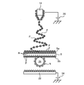
- FIG. 1 schematically shows a configuration of a nonwoven fabric manufacturing apparatus according to an embodiment of the present invention.
- the nonwoven fabric manufacturing apparatus 10 shown in FIG. 1 is configured to produce a nonwoven fabric by depositing electrospun fibers on the surface of a base sheet.
- the “fiber” referred to in the present specification refers to a filamentous material made of a polymer material and having a nano-order or micron-order diameter.
- polymer materials include various polymers such as petroleum-based polymers such as polyvinylidene fluoride (FVDF), polyvinylidene fluoride-co-hexafluoropropylene, polyacrylonitrile, polymethyl methacrylate, polyethylene, and polypropylene, and biopolymers. Copolymers and mixtures thereof can be applied.
- the nanofiber raw material liquid is a solution (polymer solution) in which these polymer substances are dissolved.
- the nonwoven fabric manufacturing apparatus 10 includes a sheet conveying device 12 that conveys a base sheet S, a plurality of nozzles 14 that eject a charged fiber raw material liquid toward the base sheet S, and a base material. And a collector device 16 that electrostatically attracts fibers to the sheet S.
- the base sheet S has a long shape, and the sheet transport device 12 is configured to transport the base sheet S in the transport direction L that is the long direction.
- the sheet conveying device 12 is configured by, for example, a roller 18 that winds the base sheet S.
- the plurality of nozzles 14 are a part of an electrospinning apparatus for producing a fiber by electrospinning, and are arranged on the surface Sa side of the base sheet S and at a predetermined distance from the surface Sa of the base sheet S. It is arranged above the material sheet S.
- the plurality of nozzles 14 are also arranged at intervals in the width direction of the base sheet S (the drawing depth direction).
- a positive high voltage for example, a voltage of +5 to 100 kV
- the fiber raw material liquid charged in the positive polarity is ejected from the nozzle 14 toward the surface Sa of the base sheet S.
- a single nozzle having a plurality of injection holes may be used instead of the plurality of nozzles 14 having one injection hole for injecting the fiber raw material liquid.
- the positively charged fiber raw material liquid sprayed from each of the plurality of nozzles 14 evaporates gradually before reaching the surface Sa of the base sheet S, thereby reducing the distance between charges. As a result, electrostatic explosion is repeated. A fiber is formed by electrostatic explosion, and the fiber is deposited on the surface Sa of the base sheet S.
- the collector device 16 is disposed below the base sheet S, and includes an electrode 22, a voltage application device 24 that applies a voltage to the electrode 22, a plurality of charge holding members 26, and a container that houses the charge holding members 26. 28.
- the collector device 16 serves as an attracting means for attracting (electrostatically attracting) the charged fiber (or fiber raw material liquid) to the base sheet S, and charges the fiber raw material liquid by concentrating charges on the nozzle 14.
- As the charging means it further functions as a static elimination means for neutralizing the base sheet S and the fibers deposited on the base sheet S.
- the collector device 16 functions as an attracting means and a charging means.
- the electrode 22 has a plate shape, and is disposed to face the back surface Sb of the base sheet S with a space therebetween.
- a high negative voltage (for example, a voltage of ⁇ 5 to ⁇ 35 kV) is applied to the electrode 22 by the voltage application device 24.
- the positively charged fiber is electrostatically attracted toward the base sheet S by the electrode 22 to which a negative voltage is applied. Further, the positive charge of the nozzle 14 is concentrated at the tip of the nozzle 14 in which the injection hole for injecting the fiber raw material liquid is formed, and the fiber raw material liquid is charged positively.
- the voltage applied to the electrode 22 is a potential difference that can attract the charged fiber to the base sheet S and concentrate the charge on the nozzle 14 to charge the fiber raw material liquid. Any potential can be applied between the first and second electrodes. As a result, the collector device 16 can function as an attracting means and a charging means. Therefore, for example, when a positive high voltage is applied to the nozzle 14 as in the present embodiment, the electrode 22 may be connected to ground. Further, for example, the nozzle 14 may be connected to the ground, and a voltage may be applied to the electrode 22. In the following description, it is assumed that a negative voltage is applied to the electrode 22 by the voltage application device 24.
- a plurality of charge holding members 26 are arranged between the electrode 22 of the collector device 16 and the base sheet S so as to be freely movable.
- the plurality of charge holding members 26 include openings facing the base sheet S, and the bottom Are accommodated in a container 28 in which the electrodes 22 are arranged.
- the charge holding member 26 is not limited to a conductive material or an insulating material, but is a granular material made of a material that can hold a charge. For example, a substantially spherical granule made from aluminum.
- the charge holding member 26 is also sized so that it cannot pass through the base sheet S and is not captured by the base sheet S.
- collector device 16 The operation of the collector device 16 will be described with reference to a simplified model of the collector device 16 shown in FIGS. 2A to 2F.
- a negative high voltage is applied to the electrode 22 of the collector device 16 by the voltage application device 24 before the fiber raw material liquid is injected by the nozzle 14.
- dielectric polarization occurs in the base material sheet S.
- positive charge P collects on the back surface Sb side of the base sheet S facing the electrode 22, and negative charge N collects on the surface Sa side.
- the charge holding member 26 in contact with the electrode 22 is negatively charged (the charge holding member 26 has a charge N).
- the fiber raw material liquid charged to the positive polarity by the nozzle 14 is sprayed.
- the raw material liquid sprayed from the nozzle 12 repeats electrostatic explosion, and the fiber F is formed.
- the fibers F in a positively charged state are electrostatically attracted toward the surface Sa of the base sheet S where negative charges N are collected, and are deposited on the surface Sa on the base sheet S.
- the charge holding member 26 in a negatively charged state is formed by electrostatic attraction by the fiber F in a positively charged state. , Away from the electrode 22 of the collector device 16. And it contacts the back surface Sb of the base material sheet S, as shown to FIG. 2C.
- the charge holding member 26 in a negatively charged state has a high density of positive charge P (that is, there are many nanofibers F in a positively charged state) surface of the base sheet S. It contacts the part of the back surface Sb close to the part of Sa.
- the charge holding member 26 is separated from the back surface Sb of the base sheet S by being subjected to the action of gravity as a subsidiary mainly due to electrostatic attraction by the electrode 22. Then, as shown in FIG. Then, the electrode 22 to which the negative voltage is applied causes the charge holding member 26 to be negatively charged again as shown in FIG. 2B.
- the charge holding member 26 is separated from the back surface Sb of the base sheet S. This occurs when the electrostatic attraction force that attracts electricity becomes smaller than the gravity acting on the charge holding member 26. Therefore, in this case, the charge holding member 22 is separated from the back surface Sb of the base sheet S mainly due to the action of gravity.
- the static elimination region A3 is charged to the positive polarity again and disappears as new fibers are deposited.
- the charge holding member 26 (FIG. 2B) charged again with a negative polarity is electrostatically attracted to another position having a strong positive polarity and comes into contact with the back surface Sb of the base sheet S, thereby neutralizing the region. In this way, the state shown in FIGS. 2B to 2F is repeated until the injection of the fiber raw material liquid from the nozzle 14 is stopped.
- a collector device 16 in a substantially non-contact state with the base material sheet S, that is, even when the back surface Sb of the base material sheet S is not always in surface contact, it is on the surface Sa of the base material sheet S.
- the accumulated charged fiber F can be neutralized.
- dielectric polarization can be generated in the base sheet S. Since the collector device 16 and the base sheet S are substantially non-contact, the sheet transport device 12 can transport the base sheet S more easily than a conventional collector device having a contact-type collector electrode. Can do.
- FIG. 3 is a diagram of the base sheet S viewed in the conveying direction in the nonwoven fabric manufacturing apparatus 10 according to the embodiment of the present invention.
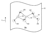
- FIG. 4 is a view of the base sheet S viewed from above in the nonwoven fabric manufacturing apparatus 10 according to the embodiment of the present invention.
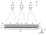
- FIG. 5 is the figure which looked at the base material sheet S in the conveyance direction in the nonwoven fabric manufacturing apparatus of a comparative example.
- FIG. 6 is a view of the base sheet S viewed from above in the nonwoven fabric manufacturing apparatus of the comparative example.
- the non-woven fabric manufacturing apparatus 50 shown in FIG. 5 differs from the collector apparatus 16 according to the present invention in that the collector electrode 52 is always in surface contact over the entire back surface Sb of the base sheet S, and the voltage that applies a negative voltage to the collector electrode 52.
- An application device 54 and a plurality of nozzles 56 that inject the charged fiber raw material liquid toward the base sheet S are provided.
- positively charged fibers are deposited on the surface Sa of the base sheet S.
- the collector electrode 52 when the collector electrode 52 is always in surface contact with the base sheet S, the charged fiber is deposited on the surface Sa of the base sheet S and immediately passes through the collector electrode 52. To be neutralized. Therefore, the density of the positive charge P on the surface Sa of the base sheet S is uniform.
- the fiber is likely to be deposited immediately below the nozzle 56 that is the surface Sa at the shortest position from the sprayed position. Furthermore, the fibers produced from the raw material liquid ejected from each of the plurality of nozzles 56 are electrostatically repelled. Due to these factors, the accumulation range of the fibers ejected from the nozzles 56 is a direction perpendicular to the parallel direction of the plurality of nozzles 56 (that is, the width direction of the base sheet S) (that is, the transport direction of the base sheet S). It becomes an elongated oval shape.
- the portion A1 where the fibers are deposited at a high density and the portion A2 where the fibers are deposited at a low density are alternately formed in the parallel direction of the plurality of nozzles 56 (that is, the width direction of the base sheet S).
- the problem occurs.
- the fibers lined up in the transport direction increase by being accumulated in an elongated elliptical shape. Therefore, when the nonwoven fabric finally produced receives the tensile force of the width direction, it is easy to tear to a longitudinal direction.
- the density of the positive charges P on the surface Sa of the base sheet S is not uniform but varies depending on the position. Specifically, the density of the positive charge P is reduced in the charge removal region A3 which is a portion immediately after the charge is removed by the charge holding member 26 in a negatively charged state.
- the charge holding member 26 can freely move between the base sheet S and the electrode 22, as shown in FIG. 4, random timing (random width direction position and longitudinal position) at random timing.
- the static elimination area A3 is spot-generated on the surface Sa of the base sheet S.
- the fibers in the positively charged state are scattered and accumulated toward the static elimination region A3 (position where the fiber is easily deposited) where the density of the positive charge P is low, so that the static elimination region A3 is randomly positioned as described above.
- the fiber deposition position also moves randomly.
- the density of the fiber is uneven because the position where the fiber is likely to be deposited does not change.
- the problem of density unevenness occurs because the static elimination region A3, which is the position where the fiber is likely to be deposited, varies. As a result, the fibers are uniformly deposited over the entire surface Sa of the base sheet S. Further, as shown in FIG.
- the base sheet S and the collector device 16 are substantially non-contact, that is, the base sheet does not come into surface contact with the collector device 16 and does not strongly electrostatically adsorb.
- the transportability of the sheet S is improved.
- the collector device according to the present invention is not limited to the collector device 16 described above, and various forms are possible.
- FIG. 7 shows a collector device 116 according to another embodiment.
- the collector device 116 includes an electrode 122, a voltage application device 124 that applies a negative voltage to the electrode 122, a plurality of granular charge holding members 126, and a guide member 128 that regulates the moving direction of the charge holding member 126.
- a voltage application device 124 that applies a negative voltage to the electrode 122
- a plurality of granular charge holding members 126 a plurality of granular charge holding members 126
- a guide member 128 that regulates the moving direction of the charge holding member 126.
- the guide member 128 is a cylindrical member that extends from the electrode 122 toward the base sheet S, and accommodates the charge holding member 126 therein.
- the guide member 128 regulates the movement direction of each of the charge holding members 126 and suppresses the charge holding members 126 from being gathered locally in a lump.
- the collector device 116 shown in FIG. 7 can function in the same manner as the collector device 16 of the above-described embodiment.
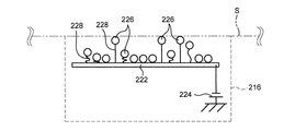
- FIG. 8 shows a collector device 216 of still another embodiment.
- the collector device 216 includes an electrode 222, a voltage application device 224 that applies a negative voltage to the electrode 222, a plurality of granular charge holding members 226, and a thread-like member 228 that connects the charge holding member 226 to the electrode 222.
- a voltage application device 224 that applies a negative voltage to the electrode 222
- a plurality of granular charge holding members 226, and a thread-like member 228 that connects the charge holding member 226 to the electrode 222.
- the thread-like member 228 is a freely deformable thread-like member, and by connecting the charge holding member 226 and the electrode 222, the antistatic member 226 is prevented from spilling from the electrode 222, and the charge holding member 226. Is maintained between the base sheet S and the electrode 222. That is, the container 28 shown in FIG. 1 is not necessary.
- the thread member 228 is also made of an insulating material. As shown in FIG. 8, when the charge holding member 226 is in contact with the base material sheet 226, electricity is prevented between the base material sheet S and the electrode 222 via the thread-like member 228.
- Such a collector device 226 shown in FIG. 8 can also function in the same manner as the collector device 16 of the above-described embodiment.
- FIG. 9 shows a collector device 316 of still another embodiment.
- the collector device 316 includes an electrode 322, a voltage application device 324 that applies a negative voltage to the electrode 322, a plurality of granular charge holding members 326, and a support member 328 that supports the charge holding member 326 in a suspended state.
- the support member 328 is a thread-like member having a free end to which the charge holding member 326 is attached and a fixed end. Further, the support member 328 supports the charge holding member 326 so as to be positioned at an intermediate position between the base sheet S and the electrode 322 while the nonwoven fabric manufacturing apparatus is stopped (when the voltage application devices of the nozzle and the electrode are stopped). ing. Accordingly, when a positively charged fiber is deposited on the base sheet S, the charge holding member 326 is electrostatically attracted toward the base sheet S and comes into contact with the base sheet S, and the fiber is neutralized. Electrostatic attraction toward the electrode 322 makes contact with the electrode 322. That is, the charge holding member 326 behaves like this.
- Such a collector device 316 makes it possible to electrostatically attract the fiber to the base sheet S in a state of extending in a non-horizontal direction (for example, the vertical direction). Moreover, it can function similarly to the collector apparatus 16 of the above-mentioned embodiment.
- FIG. 10 shows a collector device 416 of a further different embodiment.
- the collector device 416 includes an electrode 422, a voltage application device 424 that applies a negative voltage to the electrode 422, and a plurality of strip-like or thread-like charge holding members 426.
- the charge holding member 426 is formed of a band-like or thread-like member having a free end that can contact the base sheet S and the electrode 422.
- the charge holding member 426 includes a free end 426a made of a material capable of holding charge and a main body 426b made of an insulating material.
- the charge holding member 426 is manufactured by attaching a metal body to the free end of a strip-shaped insulator.
- the collector device 416 having the charge holding member 426 can electrostatically attract the positively charged fiber toward the base sheet S regardless of the posture of the base sheet S.
- the fiber (raw material liquid) is charged to positive polarity, but may be charged to negative polarity.
- a positive voltage is applied to the electrode 22 of the collector device 16 or ground is connected.
- the collector device 16 concentrates the electric charge on the nozzle 14 as an attracting means for attracting the charged fiber (or fiber raw material liquid) to the base sheet S (electrostatic attraction). It can function as a charging means for charging the fiber raw material liquid.
- the shape, the material, and the number of the charge holding member are not limited as long as the charge holding member can hold an electric charge and can be moved by the action of electrostatic attraction.
- the charge holding member it is preferable that the charge holding member be as light as possible so that it can be reliably moved from the electrode toward the base material sheet (for example, can be lifted) under the action of electrostatic attraction.
- the charge holding member has as large a surface area as possible so that a strong electrostatic attraction force acts on the charge holding member so that the charge holding amount of the charge holding member increases.
- the present invention is not limited to the case where fibers are deposited on the surface of a long sheet while being conveyed in the longitudinal direction as in the above-described embodiment.
- the fibers are deposited simultaneously on the surface of a plurality of substrate sheets.
- the present invention can also be applied to the case of performing (that is, batch processing).
- the present invention is applicable as long as the charged fiber is electrostatically attracted onto the substrate sheet by the collector device.
Landscapes
- Engineering & Computer Science (AREA)
- Textile Engineering (AREA)
- Mechanical Engineering (AREA)
- Nonwoven Fabrics (AREA)
- Spinning Methods And Devices For Manufacturing Artificial Fibers (AREA)
Abstract
Description
Claims (16)
- 第1の極性に帯電された状態のファイバーを基材シートの表面に静電誘引して堆積する不織布製造装置のコレクタ装置であって、
基材シートの裏面に間隔をあけて対向配置され第1の極性と逆極性の第2の極性の電圧が印加されたもしくはアースに接続された電極と、
基材シートと前記電極との間に配置されて基材シートの裏面への接触と離反をランダムに繰り返す複数の電荷保持部材と、を有するコレクタ装置。 - 前記電荷保持部材が、スポット的に基材シートの裏面に接触する、請求項1に記載のコレクタ装置。
- 電荷保持部材が、複数の粒状体である、請求項1または2に記載のコレクタ装置。
- 電荷保持部材が、基材シートと電極とに接触可能な自由端を備える帯状体または糸状体である、請求項1または2に記載のコレクタ装置。
- 電荷保持部材を収容して該電荷保持部材の移動方向を規制する、電極から基材シートに向かって延びる筒状のガイド部材を有する、請求項1または2に記載のコレクタ装置。
- 電界紡糸によって生成されたファイバーを基材シートの表面に堆積させる不織布製造装置であって、
基材シートを搬送するシート搬送装置と、
基材シートの表面側に配置されて高分子溶液を噴出するノズルと、
基材シートの裏面に間隔をあけて対向配置された電極と、
前記ノズルと電極間に電位差を付与することによりノズルから噴出される高分子溶液を帯電させる帯電手段と、
基材シートと前記電極との間に配置されて基材シートの裏面への接触と離反をランダムに繰り返す複数の電荷保持部材と、を有する不織布製造装置。 - 前記電荷保持部材が、スポット的に基材シートの裏面に接触する、請求項6に記載の不織布製造装置。
- 電荷保持部材が、複数の粒状体である、請求項6または7に記載の不織布製造装置。
- 電荷保持部材が、基材シートと電極とに接触可能な自由端を備える帯状体または糸状体である、請求項6または7に記載の不織布製造装置。
- 電荷保持部材を収容して該電荷保持部材の移動方向を規制する、電極から基材シートに向かって延びる筒状のガイド部材を有する、請求項6または7に記載の不織布製造装置。
- 基材シートが、電極の上方に位置する、請求項6から10のいずれか一項に記載の不織布製造装置。
- 電界紡糸によって生成されたファイバーを基材シートの表面に堆積させる不織布製造方法であって、
基材シートと該基材シートの裏面に間隔をあけて対向配置された電極との間に移動可能な複数の電荷保持部材を配置し、電界紡糸により第1の極性に帯電したファイバーの極性とは逆極性である第2の極性の電圧を前記電極に印加もしくは前記電極をアースに接続した状態で前記ファイバーを基材シートの表面に堆積させ、
電荷保持部材が前記電極によって第2の極性に帯電する工程と、帯電した状態で基材シートの裏面へ接触する工程と、基材シートの裏面から離反して前記電極によって再び第2の極性に帯電するサイクルをランダムに繰り返すことにより、当該接触部分におけるファイバーの除電を行い、当該接触部分へのファイバーを静電誘引する、不織布製造方法。 - 前記電荷保持部材が、スポット的に基材シートの裏面に接触する、請求項12に記載の不織布製造方法。
- 電荷保持部材が、複数の粒状体である、請求項12または13に記載の不織布製造方法。
- 電荷保持部材が、基材シートと電極とに接触可能な自由端を備える帯状体または糸状体である、請求項12または13に記載の不織布製造方法。
- 電荷保持部材を収容して該電荷保持部材の移動方向を規制する、電極から基材シートに向かって延びる筒状のガイド部材を有する、請求項12または13に記載の不織布製造方法。
Priority Applications (2)
| Application Number | Priority Date | Filing Date | Title |
|---|---|---|---|
| US14/234,283 US9138931B2 (en) | 2011-07-22 | 2012-06-29 | Collector device, non-woven fabric manufacturing apparatus, and non-woven fabric manufacturing method |
| JP2013525556A JP5438868B2 (ja) | 2011-07-22 | 2012-06-29 | コレクタ装置、不織布製造装置、および不織布製造方法 |
Applications Claiming Priority (2)
| Application Number | Priority Date | Filing Date | Title |
|---|---|---|---|
| JP2011161175 | 2011-07-22 | ||
| JP2011-161175 | 2011-07-22 |
Publications (1)
| Publication Number | Publication Date |
|---|---|
| WO2013014861A1 true WO2013014861A1 (ja) | 2013-01-31 |
Family
ID=47600739
Family Applications (1)
| Application Number | Title | Priority Date | Filing Date |
|---|---|---|---|
| PCT/JP2012/004237 WO2013014861A1 (ja) | 2011-07-22 | 2012-06-29 | コレクタ装置、不織布製造装置、および不織布製造方法 |
Country Status (3)
| Country | Link |
|---|---|
| US (1) | US9138931B2 (ja) |
| JP (1) | JP5438868B2 (ja) |
| WO (1) | WO2013014861A1 (ja) |
Cited By (1)
| Publication number | Priority date | Publication date | Assignee | Title |
|---|---|---|---|---|
| CN109097842A (zh) * | 2018-08-15 | 2018-12-28 | 湖南工程学院 | 一种聚合物静电纺丝接收网帘的制备方法 |
Families Citing this family (2)
| Publication number | Priority date | Publication date | Assignee | Title |
|---|---|---|---|---|
| KR101650497B1 (ko) * | 2015-03-16 | 2016-08-23 | 전북대학교산학협력단 | 정렬된 나노섬유 제조장치 |
| CN112695389A (zh) * | 2020-12-23 | 2021-04-23 | 江苏纳纤新材料科技有限公司 | 一种消除飞丝和动态调节纤维与基材粘附力的静电纺纤维收集装置 |
Citations (4)
| Publication number | Priority date | Publication date | Assignee | Title |
|---|---|---|---|---|
| JP2008190090A (ja) * | 2007-02-07 | 2008-08-21 | Matsushita Electric Ind Co Ltd | 高分子ウェブの製造方法及び装置 |
| JP2008223187A (ja) * | 2007-03-14 | 2008-09-25 | Mecc Co Ltd | ナノ・ファイバ製造方法および装置 |
| JP2009052163A (ja) * | 2007-08-24 | 2009-03-12 | Panasonic Corp | 高分子ウエブの製造方法と装置 |
| JP2009275326A (ja) * | 2008-05-16 | 2009-11-26 | Panasonic Corp | ナノファイバ製造装置、および製造方法 |
Family Cites Families (6)
| Publication number | Priority date | Publication date | Assignee | Title |
|---|---|---|---|---|
| JP4630181B2 (ja) | 2005-09-07 | 2011-02-09 | 株式会社東海理化電機製作所 | モータリトラクタ |
| JP4903595B2 (ja) | 2007-02-09 | 2012-03-28 | パナソニック株式会社 | ナノファイバー製造方法およびナノファイバー製造装置 |
| CZ2007108A3 (cs) | 2007-02-12 | 2008-08-20 | Elmarco, S. R. O. | Zpusob a zarízení pro výrobu vrstvy nanocástic nebo vrstvy nanovláken z roztoku nebo tavenin polymeru |
| US8186987B2 (en) * | 2007-02-21 | 2012-05-29 | Panasonic Corporation | Nano-fiber manufacturing apparatus |
| JP4763845B2 (ja) | 2009-09-09 | 2011-08-31 | パナソニック株式会社 | ナノファイバ製造装置、ナノファイバ製造方法 |
| WO2012042802A1 (ja) * | 2010-09-29 | 2012-04-05 | パナソニック株式会社 | ナノファイバー製造システムおよびナノファイバー製造方法 |
-
2012
- 2012-06-29 US US14/234,283 patent/US9138931B2/en not_active Expired - Fee Related
- 2012-06-29 JP JP2013525556A patent/JP5438868B2/ja not_active Expired - Fee Related
- 2012-06-29 WO PCT/JP2012/004237 patent/WO2013014861A1/ja active Application Filing
Patent Citations (4)
| Publication number | Priority date | Publication date | Assignee | Title |
|---|---|---|---|---|
| JP2008190090A (ja) * | 2007-02-07 | 2008-08-21 | Matsushita Electric Ind Co Ltd | 高分子ウェブの製造方法及び装置 |
| JP2008223187A (ja) * | 2007-03-14 | 2008-09-25 | Mecc Co Ltd | ナノ・ファイバ製造方法および装置 |
| JP2009052163A (ja) * | 2007-08-24 | 2009-03-12 | Panasonic Corp | 高分子ウエブの製造方法と装置 |
| JP2009275326A (ja) * | 2008-05-16 | 2009-11-26 | Panasonic Corp | ナノファイバ製造装置、および製造方法 |
Cited By (2)
| Publication number | Priority date | Publication date | Assignee | Title |
|---|---|---|---|---|
| CN109097842A (zh) * | 2018-08-15 | 2018-12-28 | 湖南工程学院 | 一种聚合物静电纺丝接收网帘的制备方法 |
| CN109097842B (zh) * | 2018-08-15 | 2021-04-20 | 湖南工程学院 | 一种聚合物静电纺丝接收网帘的制备方法 |
Also Published As
| Publication number | Publication date |
|---|---|
| US20140131907A1 (en) | 2014-05-15 |
| US9138931B2 (en) | 2015-09-22 |
| JPWO2013014861A1 (ja) | 2015-02-23 |
| JP5438868B2 (ja) | 2014-03-12 |
Similar Documents
| Publication | Publication Date | Title |
|---|---|---|
| JP5111525B2 (ja) | ポリマーの溶液又は溶融物からナノパーティクル層又はナノファイバー層を製造する方法と装置 | |
| US20080150197A1 (en) | Electrostatic spinning apparatus | |
| JP5021109B2 (ja) | ナノファイバー製造システムおよびナノファイバー製造方法 | |
| JP4129261B2 (ja) | 電気紡糸法を用いたナノ繊維製造装置及びこれに採用される紡糸ノズルパック | |
| US10041189B2 (en) | Method for production of polymeric nanofibers by spinning of solution or melt of polymer in electric field | |
| US8545207B2 (en) | Roller type electrostatic spinning apparatus | |
| KR101307877B1 (ko) | 일렉트렛 필터 소자 및 그 제조 방법 | |
| JP5438868B2 (ja) | コレクタ装置、不織布製造装置、および不織布製造方法 | |
| CZ2007727A3 (cs) | Sberná elektroda zarízení pro výrobu nanovláken elektrostatickým zvláknováním polymerních matric, a zarízení obsahující tuto sbernou elektrodu | |
| JP2008174867A (ja) | 高分子ファイバ生成方法と装置、これらを用いた高分子ウエブ製造方法と装置 | |
| JP2011052337A (ja) | エレクトロスピニング装置 | |
| JP4848970B2 (ja) | 高分子ウェブの製造方法及び装置 | |
| US11384452B2 (en) | Electrospinning device and method | |
| WO2016147951A1 (ja) | ナノファイバ製造装置、及び、ナノファイバ製造方法 | |
| JP5480857B2 (ja) | 不織布製造装置および不織布製造方法 | |
| JP2018059221A (ja) | シート状の繊維堆積体の製造装置及び該繊維堆積体の製造方法 | |
| CN113710835B (zh) | 用于形成取向纤维的静电纺丝设备和方法 | |
| KR102052640B1 (ko) | 전기방사 섬유 수집 장치 및 이를 포함하는 전기방사 장치 | |
| JP2012158838A (ja) | ナノファイバー製造装置およびその方法 | |
| US11078600B2 (en) | Method and apparatus for fabricating a fibre array and structure incorporating a fibre array | |
| TWI472655B (zh) | 連續電紡設備 | |
| CZ304660B6 (cs) | Způsob a zařízení pro výrobu vrstvy vláken, zejména nanovláken, mikrovláken nebo jejich směsí, s vlákny orientovanými v jednom směru, a kolektor tohoto zařízení pro ukládání vláken | |
| JPH07161451A (ja) | コロナ放電発生装置の接地電極 |
Legal Events
| Date | Code | Title | Description |
|---|---|---|---|
| 121 | Ep: the epo has been informed by wipo that ep was designated in this application |
Ref document number: 12817969 Country of ref document: EP Kind code of ref document: A1 |
|
| ENP | Entry into the national phase |
Ref document number: 2013525556 Country of ref document: JP Kind code of ref document: A |
|
| NENP | Non-entry into the national phase |
Ref country code: DE |
|
| WWE | Wipo information: entry into national phase |
Ref document number: 14234283 Country of ref document: US |
|
| 122 | Ep: pct application non-entry in european phase |
Ref document number: 12817969 Country of ref document: EP Kind code of ref document: A1 |