WO2013011970A1 - 透光性硬質基板積層体の製造方法及び透光性硬質基板貼り合わせ装置 - Google Patents
透光性硬質基板積層体の製造方法及び透光性硬質基板貼り合わせ装置 Download PDFInfo
- Publication number
- WO2013011970A1 WO2013011970A1 PCT/JP2012/068021 JP2012068021W WO2013011970A1 WO 2013011970 A1 WO2013011970 A1 WO 2013011970A1 JP 2012068021 W JP2012068021 W JP 2012068021W WO 2013011970 A1 WO2013011970 A1 WO 2013011970A1
- Authority
- WO
- WIPO (PCT)
- Prior art keywords
- meth
- acrylate
- hard substrate
- light
- translucent hard
- Prior art date
- Legal status (The legal status is an assumption and is not a legal conclusion. Google has not performed a legal analysis and makes no representation as to the accuracy of the status listed.)
- Ceased
Links
Images







Classifications
-
- B—PERFORMING OPERATIONS; TRANSPORTING
- B32—LAYERED PRODUCTS
- B32B—LAYERED PRODUCTS, i.e. PRODUCTS BUILT-UP OF STRATA OF FLAT OR NON-FLAT, e.g. CELLULAR OR HONEYCOMB, FORM
- B32B37/00—Methods or apparatus for laminating, e.g. by curing or by ultrasonic bonding
- B32B37/14—Methods or apparatus for laminating, e.g. by curing or by ultrasonic bonding characterised by the properties of the layers
- B32B37/16—Methods or apparatus for laminating, e.g. by curing or by ultrasonic bonding characterised by the properties of the layers with all layers existing as coherent layers before laminating
- B32B37/18—Methods or apparatus for laminating, e.g. by curing or by ultrasonic bonding characterised by the properties of the layers with all layers existing as coherent layers before laminating involving the assembly of discrete sheets or panels only
-
- B—PERFORMING OPERATIONS; TRANSPORTING
- B32—LAYERED PRODUCTS
- B32B—LAYERED PRODUCTS, i.e. PRODUCTS BUILT-UP OF STRATA OF FLAT OR NON-FLAT, e.g. CELLULAR OR HONEYCOMB, FORM
- B32B37/00—Methods or apparatus for laminating, e.g. by curing or by ultrasonic bonding
- B32B37/12—Methods or apparatus for laminating, e.g. by curing or by ultrasonic bonding characterised by using adhesives
-
- C—CHEMISTRY; METALLURGY
- C03—GLASS; MINERAL OR SLAG WOOL
- C03C—CHEMICAL COMPOSITION OF GLASSES, GLAZES OR VITREOUS ENAMELS; SURFACE TREATMENT OF GLASS; SURFACE TREATMENT OF FIBRES OR FILAMENTS MADE FROM GLASS, MINERALS OR SLAGS; JOINING GLASS TO GLASS OR OTHER MATERIALS
- C03C27/00—Joining pieces of glass to pieces of other inorganic material; Joining glass to glass other than by fusing
- C03C27/06—Joining glass to glass by processes other than fusing
- C03C27/10—Joining glass to glass by processes other than fusing with the aid of adhesive specially adapted for that purpose
-
- C—CHEMISTRY; METALLURGY
- C08—ORGANIC MACROMOLECULAR COMPOUNDS; THEIR PREPARATION OR CHEMICAL WORKING-UP; COMPOSITIONS BASED THEREON
- C08F—MACROMOLECULAR COMPOUNDS OBTAINED BY REACTIONS ONLY INVOLVING CARBON-TO-CARBON UNSATURATED BONDS
- C08F222/00—Copolymers of compounds having one or more unsaturated aliphatic radicals, each having only one carbon-to-carbon double bond, and at least one being terminated by a carboxyl radical and containing at least one other carboxyl radical in the molecule; Salts, anhydrides, esters, amides, imides, or nitriles thereof
- C08F222/10—Esters
- C08F222/1006—Esters of polyhydric alcohols or polyhydric phenols
- C08F222/102—Esters of polyhydric alcohols or polyhydric phenols of dialcohols, e.g. ethylene glycol di(meth)acrylate or 1,4-butanediol dimethacrylate
-
- C—CHEMISTRY; METALLURGY
- C08—ORGANIC MACROMOLECULAR COMPOUNDS; THEIR PREPARATION OR CHEMICAL WORKING-UP; COMPOSITIONS BASED THEREON
- C08F—MACROMOLECULAR COMPOUNDS OBTAINED BY REACTIONS ONLY INVOLVING CARBON-TO-CARBON UNSATURATED BONDS
- C08F222/00—Copolymers of compounds having one or more unsaturated aliphatic radicals, each having only one carbon-to-carbon double bond, and at least one being terminated by a carboxyl radical and containing at least one other carboxyl radical in the molecule; Salts, anhydrides, esters, amides, imides, or nitriles thereof
- C08F222/10—Esters
- C08F222/1006—Esters of polyhydric alcohols or polyhydric phenols
- C08F222/106—Esters of polycondensation macromers
- C08F222/1065—Esters of polycondensation macromers of alcohol terminated (poly)urethanes, e.g. urethane(meth)acrylates
-
- C—CHEMISTRY; METALLURGY
- C09—DYES; PAINTS; POLISHES; NATURAL RESINS; ADHESIVES; COMPOSITIONS NOT OTHERWISE PROVIDED FOR; APPLICATIONS OF MATERIALS NOT OTHERWISE PROVIDED FOR
- C09D—COATING COMPOSITIONS, e.g. PAINTS, VARNISHES OR LACQUERS; FILLING PASTES; CHEMICAL PAINT OR INK REMOVERS; INKS; CORRECTING FLUIDS; WOODSTAINS; PASTES OR SOLIDS FOR COLOURING OR PRINTING; USE OF MATERIALS THEREFOR
- C09D4/00—Coating compositions, e.g. paints, varnishes or lacquers, based on organic non-macromolecular compounds having at least one polymerisable carbon-to-carbon unsaturated bond ; Coating compositions, based on monomers of macromolecular compounds of groups C09D183/00 - C09D183/16
-
- C—CHEMISTRY; METALLURGY
- C09—DYES; PAINTS; POLISHES; NATURAL RESINS; ADHESIVES; COMPOSITIONS NOT OTHERWISE PROVIDED FOR; APPLICATIONS OF MATERIALS NOT OTHERWISE PROVIDED FOR
- C09J—ADHESIVES; NON-MECHANICAL ASPECTS OF ADHESIVE PROCESSES IN GENERAL; ADHESIVE PROCESSES NOT PROVIDED FOR ELSEWHERE; USE OF MATERIALS AS ADHESIVES
- C09J5/00—Adhesive processes in general; Adhesive processes not provided for elsewhere, e.g. relating to primers
-
- G—PHYSICS
- G02—OPTICS
- G02F—OPTICAL DEVICES OR ARRANGEMENTS FOR THE CONTROL OF LIGHT BY MODIFICATION OF THE OPTICAL PROPERTIES OF THE MEDIA OF THE ELEMENTS INVOLVED THEREIN; NON-LINEAR OPTICS; FREQUENCY-CHANGING OF LIGHT; OPTICAL LOGIC ELEMENTS; OPTICAL ANALOGUE/DIGITAL CONVERTERS
- G02F1/00—Devices or arrangements for the control of the intensity, colour, phase, polarisation or direction of light arriving from an independent light source, e.g. switching, gating or modulating; Non-linear optics
- G02F1/01—Devices or arrangements for the control of the intensity, colour, phase, polarisation or direction of light arriving from an independent light source, e.g. switching, gating or modulating; Non-linear optics for the control of the intensity, phase, polarisation or colour
- G02F1/13—Devices or arrangements for the control of the intensity, colour, phase, polarisation or direction of light arriving from an independent light source, e.g. switching, gating or modulating; Non-linear optics for the control of the intensity, phase, polarisation or colour based on liquid crystals, e.g. single liquid crystal display cells
- G02F1/1303—Apparatus specially adapted to the manufacture of LCDs
-
- B—PERFORMING OPERATIONS; TRANSPORTING
- B32—LAYERED PRODUCTS
- B32B—LAYERED PRODUCTS, i.e. PRODUCTS BUILT-UP OF STRATA OF FLAT OR NON-FLAT, e.g. CELLULAR OR HONEYCOMB, FORM
- B32B38/00—Ancillary operations in connection with laminating processes
- B32B2038/0052—Other operations not otherwise provided for
- B32B2038/0076—Curing, vulcanising, cross-linking
-
- B—PERFORMING OPERATIONS; TRANSPORTING
- B32—LAYERED PRODUCTS
- B32B—LAYERED PRODUCTS, i.e. PRODUCTS BUILT-UP OF STRATA OF FLAT OR NON-FLAT, e.g. CELLULAR OR HONEYCOMB, FORM
- B32B2307/00—Properties of the layers or laminate
- B32B2307/40—Properties of the layers or laminate having particular optical properties
- B32B2307/414—Translucent
-
- B—PERFORMING OPERATIONS; TRANSPORTING
- B32—LAYERED PRODUCTS
- B32B—LAYERED PRODUCTS, i.e. PRODUCTS BUILT-UP OF STRATA OF FLAT OR NON-FLAT, e.g. CELLULAR OR HONEYCOMB, FORM
- B32B2310/00—Treatment by energy or chemical effects
- B32B2310/08—Treatment by energy or chemical effects by wave energy or particle radiation
- B32B2310/0806—Treatment by energy or chemical effects by wave energy or particle radiation using electromagnetic radiation
- B32B2310/0837—Treatment by energy or chemical effects by wave energy or particle radiation using electromagnetic radiation using actinic light
-
- B—PERFORMING OPERATIONS; TRANSPORTING
- B32—LAYERED PRODUCTS
- B32B—LAYERED PRODUCTS, i.e. PRODUCTS BUILT-UP OF STRATA OF FLAT OR NON-FLAT, e.g. CELLULAR OR HONEYCOMB, FORM
- B32B38/00—Ancillary operations in connection with laminating processes
- B32B38/18—Handling of layers or the laminate
- B32B38/1825—Handling of layers or the laminate characterised by the control or constructional features of devices for tensioning, stretching or registration
- B32B38/1833—Positioning, e.g. registration or centering
- B32B38/1841—Positioning, e.g. registration or centering during laying up
-
- C—CHEMISTRY; METALLURGY
- C09—DYES; PAINTS; POLISHES; NATURAL RESINS; ADHESIVES; COMPOSITIONS NOT OTHERWISE PROVIDED FOR; APPLICATIONS OF MATERIALS NOT OTHERWISE PROVIDED FOR
- C09J—ADHESIVES; NON-MECHANICAL ASPECTS OF ADHESIVE PROCESSES IN GENERAL; ADHESIVE PROCESSES NOT PROVIDED FOR ELSEWHERE; USE OF MATERIALS AS ADHESIVES
- C09J2301/00—Additional features of adhesives in the form of films or foils
- C09J2301/40—Additional features of adhesives in the form of films or foils characterized by the presence of essential components
- C09J2301/416—Additional features of adhesives in the form of films or foils characterized by the presence of essential components use of irradiation
-
- C—CHEMISTRY; METALLURGY
- C09—DYES; PAINTS; POLISHES; NATURAL RESINS; ADHESIVES; COMPOSITIONS NOT OTHERWISE PROVIDED FOR; APPLICATIONS OF MATERIALS NOT OTHERWISE PROVIDED FOR
- C09J—ADHESIVES; NON-MECHANICAL ASPECTS OF ADHESIVE PROCESSES IN GENERAL; ADHESIVE PROCESSES NOT PROVIDED FOR ELSEWHERE; USE OF MATERIALS AS ADHESIVES
- C09J2433/00—Presence of (meth)acrylic polymer
Definitions
- the present invention relates to a method for producing a light-transmitting hard substrate laminate and a light-transmitting hard substrate laminating apparatus, and more particularly to a method for producing a plate glass laminate for producing protective glass for display elements and a process for producing protective glass for display elements.
- the present invention relates to a sheet glass laminating apparatus used for the above.
- Display devices of various electronic devices such as TVs, notebook computers, car navigation systems, calculators, mobile phones, electronic notebooks, and PDAs (Personal Digital Assistants) include liquid crystal displays (LCD), organic EL displays (OELD), electroluminescent displays ( Display elements such as ELD), field emission displays (FED), and plasma displays (PDP) are used. And in order to protect a display element, it is common to install the plate glass product for protection facing a display element.
- LCD liquid crystal displays
- OELD organic EL displays
- ELD electroluminescent displays
- FED field emission displays
- PDP plasma displays
- This flat glass product is obtained by processing a flat glass into a size and shape suitable for each display device. In order to meet the price level required in the market, it is possible to process a large amount of flat glass products with high production efficiency. Desired.
- Patent Document 1 proposes a method for increasing the production efficiency of a sheet glass product. Specifically, “a large number of material glass sheets (1) are stacked, and each material glass sheet (1) is integrally fixed by a peelable fixing material (2) interposed between each material glass sheet (1). Forming the material glass block (A), dividing the material glass block (A) in the plane direction to form a small-area divided glass block (B), and processing at least the outer periphery of the divided glass block (B) A product glass block (C) having a product shape in plan view is formed, and after the end face processing of the product glass block (C), the product glass block (C) is individually separated. “Processing method” is proposed (claim 1).
- Patent Document 1 states that “the fixing material (2) interposed between the respective material glass plates (1) is cured when irradiated with ultraviolet rays, and is cured by softening the cured state when heated. It is described that “the material is used” (claim 4).
- the material is used” (claim 4).
- the liquid sticking agent spreads in a film with a uniform thickness over the entire surface between the upper and lower material plate glasses. In this state, when the infrared rays are irradiated, the liquid sticking agent spread in the form of a film is cured and the upper and lower plate glasses are fixed together, so that a large number of material plate glasses are stacked quickly and accurately.
- Patent Document 1 According to the processing method of plate glass described in Patent Document 1, it is possible to manufacture a plate glass product having a predetermined shape with high production efficiency. However, depending on the electronic device, it may be required to form a desired print pattern (for example, the design of a display screen of a mobile phone) on the plate glass. In such a case, the printed pattern has high positional accuracy. (For example, an allowable error of about 10 to 30 ⁇ m) is required.
- Patent Document 1 discloses an invention of a method of bonding glass, it does not describe an apparatus for realizing the method. For industrial mass production, it is desirable to provide an apparatus capable of laminating glass.
- an object of the present invention is to provide a method for manufacturing a light-transmitting hard substrate laminate capable of improving the positional accuracy. Moreover, this invention makes it another subject to provide the manufacturing method of the plate-shaped product using the manufacturing method of the said translucent hard board
- the present inventor has intensively studied to solve the above problems, and when the light-transmitting hard substrates are bonded together in a predetermined positional relationship with a photo-curable fixing agent interposed therebetween, the light-transmitting hard substrate is attached. It has been found that it is effective to cure the entire fixing agent which is sandwiched between both light-transmitting hard substrates and spread each time the substrates are bonded. By curing the fixing agent each time the light-transmitting hard substrates are bonded, the light-transmitting hard substrates are firmly bonded to each other.
- the light-transmitting hard substrate laminate having been bonded is waited at the upper side, and the next light-transmitting hard substrate to be laminated is supplied from the lower side, toward the lower light-transmitting hard substrate from the lower side. It has been found that by adopting a configuration of irradiating light, the number of components of the translucent hard substrate laminate can be increased efficiently.
- the present invention completed on the basis of the above knowledge, in one aspect, 1) preparing a first translucent hard substrate; 2) preparing a second translucent hard substrate; 3) (A) polyfunctional (meth) acrylate, (B) monofunctional (meta) on the first surface of the first translucent hard substrate and / or the first surface of the second translucent hard substrate. Applying a photocurable fixing agent containing acrylate) and (C) a photopolymerization initiator; 4) The process of making the 1st surface of a 1st translucent hard board
- Steps 1) to 6) are repeated at least once with the light-transmitting hard substrate laminate as the first light-transmitting hard substrate, and at least three light-transmitting hard substrates are bonded together. And a process for forming a light-transmitting hard substrate laminate.
- step 6 is performed by irradiating light toward the surface of the second translucent hard substrate.
- step 5) between step 5) and step 6), 5 ′) Applying light having lower energy than in step 6) to the whole or a part of the spreading agent sandwiched between both translucent hard substrates to form a temporary translucent hard substrate laminate.
- step 6 Between step 5) and step 6), 5 ′) Applying light having lower energy than in step 6) to the whole or a part of the spreading agent sandwiched between both translucent hard substrates to form a temporary translucent hard substrate laminate. Process, May further be included.
- a mark for alignment is attached to the surface of each light-transmitting hard substrate. Including adjusting the position while imaging with an imaging device.
- a predetermined printing pattern for performing one of the functions of a plate-like product on the surface of each light-transmitting hard substrate and A plating pattern is attached.
- the fixing agent contains a particulate material.
- the light irradiation amount in step 6) is measured by an integrating illuminometer using a 365 nm light receiver, the amount of irradiation is in the range of 30mJ / cm 2 ⁇ 4000mJ / cm 2.
- the light-transmitting hard substrate is a plate glass.
- the divided light-transmitting hard substrate laminate is sandwiched between the light-transmitting hard substrates between step 8) and step 9).
- the method further includes a step of contacting the release agent at a temperature and a time condition necessary to reduce the adhesion of the exposed portion of the outer edge of the adhesive.
- the release agent contains one or more selected from a solvent, an oxidant, and a surfactant.
- the release agent contains one or more selected from water, alcohols, oxidizing agents, and surfactants.
- the release agent contains water, alcohols and a surfactant in a mass ratio of 30 to 50:30 to 50: 5 to 20.
- the release agent contains benzyl alcohol.
- the release agent contains an anionic surfactant.
- the release agent contains a sulfonic acid type surfactant.
- the liquid temperature of the release agent is 50 ° C. or less, and the contact time with the release agent is 1 to 20 minutes.
- the polyfunctional (meth) acrylate is a polyfunctional (meth) acrylate oligomer / polymer and / or bifunctional ( Contains a (meth) acrylate monomer.
- (B) monofunctional (meth) acrylate is phenol ethylene oxide 2 mol-modified (meth) acrylate, 2- (1 , 2-cyclohexacarboximido) ethyl (meth) acrylate and 2-hydroxy-3-phenoxypropyl (meth) acrylate.
- (B) monofunctional (meth) acrylate is a phenol ethylene oxide 2 mol-modified (meth) acrylate and 2- (1 , 2-cyclohexacarboximido) ethyl (meth) acrylate.
- (B) monofunctional (meth) acrylate is phenol ethylene oxide 2 mol modified (meth) acrylate and 2-hydroxy- Contains 3-phenoxypropyl (meth) acrylate.
- the fixing agent is a two-component composition
- the first agent contains at least (F) an organic peroxide.
- the second agent contains at least (G) a decomposition accelerator.
- An upper stage for holding the upper translucent hard substrate having a suction hole for vacuum adsorbing the upper translucent hard substrate;
- a press unit capable of moving the upper stage in the Z-axis direction;
- a suction unit for applying a suction force to the suction hole;
- a lower stage for holding the lower translucent hard substrate;
- a light irradiation unit for irradiating light from below toward the entire surface of the lower translucent hard substrate; It is the translucent hard board
- substrate bonding apparatus provided with.
- an imaging unit that images alignment marks provided on the upper and lower translucent hard substrates, and an upper side based on the imaging result
- an image processing unit for detecting the degree of positional deviation of the alignment mark provided on the lower surface, and a control unit for controlling the lower stage moving means based on the detected degree of positional deviation.
- the substrates can be stacked with higher positional accuracy by finely adjusting the positional relationship between the translucent hard substrates using the imaging unit. Therefore, it is possible to handle even when high positional accuracy is required, such as when a printed pattern or plating pattern is attached to the surface of the translucent hard substrate.
- the translucent hard substrate held by the upper stage and / or the lower stage is a laminate of two or more translucent hard substrates. Is the body.
- the upper and / or lower translucent hard substrates to be bonded together in the present invention into a laminate composed of two or more translucent hard substrates, three or more substrate laminates can be produced.
- the translucent hard substrate is a plate glass.
- the polyfunctional (meth) acrylate is a polyfunctional (meth) acrylate oligomer / polymer and / or bifunctional (meth). Contains acrylate monomers.
- (B) monofunctional (meth) acrylate is phenol ethylene oxide 2 mol modified (meth) acrylate, 2- (1,2 -Cyclohexacarboximido) ethyl (meth) acrylate and one or more of the group consisting of 2-hydroxy-3-phenoxypropyl (meth) acrylate.
- (B) monofunctional (meth) acrylate is phenol ethylene oxide 2 mol modified (meth) acrylate and 2- (1,2 -Containing cyclohexacarboximido) ethyl (meth) acrylate.
- (B) monofunctional (meth) acrylate is phenol ethylene oxide 2 mol modified (meth) acrylate and 2-hydroxy-3- Contains phenoxypropyl (meth) acrylate.
- the fixing agent is a two-component composition, and the first agent contains at least (F) an organic peroxide.
- the second agent contains at least (G) a decomposition accelerator.
- a translucent hard substrate laminate can be manufactured with high positional accuracy.
- a plate-shaped product can be manufactured industrially with high dimensional accuracy.
- the present invention can be suitably used, for example, in a method for mass-producing protective glass for display elements.
- a translucent hard substrate to be processed is prepared.
- the light-transmitting hard substrate is not particularly limited, but plate glass (material plate glass, glass substrate with a transparent conductive film, glass substrate on which electrodes and circuits are formed, etc.), sapphire substrate, quartz substrate, plastic substrate, magnesium fluoride Examples include substrates.
- Examples of the glass include tempered glass. Not particularly limited on the size of the light-transmitting hard substrate, but typically have a 2 degree of area 10000 ⁇ 250000mm, having a thickness of about 0.1 ⁇ 2 mm.
- Each translucent hard substrate is generally the same size.
- substrate can be attached
- An example of the print pattern is a design of a display screen of a mobile phone, and an example of the plating pattern is a rotary encoder provided with a chrome plating pattern.
- a photo-curable fixing agent is applied to the first surface of the first translucent hard substrate and / or the first surface of the second translucent hard substrate.
- the photo-curable sticking agent is a sticking agent that is cured by irradiation with light such as ultraviolet rays and softens when heated to a high temperature, and various sticking agents are known.
- the photocurable fixing agent used in the present invention any known one can be used and there is no particular limitation.
- the photo-curable sticking agent may be applied to the bonding surface of either one of the light-transmitting hard substrates, but from the viewpoint of improving adhesiveness, it should be applied to the bonding surfaces of both of the light-transmitting hard substrates. Is preferred.
- photo-curable fixing agent suitably used in the present invention, (A) a polyfunctional (meth) acrylate, (B) a monofunctional (meth) acrylate, and (C) an adhesive containing a photopolymerization initiator.
- a composition a polyfunctional (meth) acrylate, (B) a monofunctional (meth) acrylate, and (C) an adhesive containing a photopolymerization initiator.
- (A) As a polyfunctional (meth) acrylate two or more (meth) acryloylated polyfunctional (meth) acrylate oligomer / polymer or two or more (meth) acryloyl groups at the oligomer / polymer terminal or side chain Polyfunctional (meth) acrylate monomers having can be used.
- 1,2-polybutadiene-terminated urethane (meth) acrylate for example, “TE-2000”, “TEA-1000” manufactured by Nippon Soda Co., Ltd.
- hydrogenated product thereof for example, “TEAI-1000” manufactured by Nippon Soda Co., Ltd.
- 1,4-polybutadiene terminated urethane (meth) acrylate eg “BAC-45” manufactured by Osaka Organic Chemical Co., Ltd.
- polyisoprene terminated (meth) acrylate for example, “UV-2000B”, “UV-3000B”, “UV-7000B” manufactured by Nippon Synthetic Chemical Co., Ltd.
- polyester-based urethane (meth) acrylate and / or polyether-based urethane (meth) acrylate are preferable, and polyester-based urethane (meth) acrylate is more preferable because of its great effect.
- the weight average molecular weight of the polyfunctional (meth) acrylate oligomer / polymer is preferably 5000 to 60000, more preferably 13000 to 40000.
- the weight average molecular weight was determined by creating a calibration curve with commercially available standard polystyrene using a GPC system (SC-8010 manufactured by Tosoh Corporation).
- bifunctional (meth) acrylate monomer examples include 1,3-butylene glycol di (meth) acrylate, 1,4-butanediol di (meth) acrylate, 1,6-hexanediol di (meth) acrylate, 1,9- Nonanediol di (meth) acrylate, neopentyl glycol di (meth) acrylate, dicyclopentanyl di (meth) acrylate, 2-ethyl-2-butyl-propanediol di (meth) acrylate, neopentyl glycol modified trimethylolpropane Di (meth) acrylate, stearic acid-modified pentaerythritol di (meth) acrylate, polypropylene glycol di (meth) acrylate, 2,2-bis (4- (meth) acryloxydiethoxyphenyl) propane, 2,2-bis (4- (meth) acryl Propoxy phenyl
- 1,6-hexadiol di (meth) acrylate and / or dicyclopentanyl di (meth) acrylate is preferable, and dicyclopentanyl di (meth) acrylate is more preferable from the viewpoint of great effect.
- trifunctional (meth) acrylate monomer examples include trimethylolpropane tri (meth) acrylate, tris [(meth) acryloxyethyl] isocyanurate, and the like.
- Examples of the tetrafunctional or higher (meth) acrylate monomer include dimethylolpropane tetra (meth) acrylate, pentaerythritol tetra (meth) acrylate, pentaerythritol ethoxytetra (meth) acrylate, dipentaerythritol penta (meth) acrylate, or dipenta Examples include erythritol hexa (meth) acrylate.
- polyfunctional (meth) acrylates it is preferable to contain a polyfunctional (meth) acrylate oligomer / polymer and / or a bifunctional (meth) acrylate monomer in terms of high effect. It is more preferable to use a polymer and a bifunctional (meth) acrylate monomer in combination.
- the content ratio is 100 parts by mass in total of the polyfunctional (meth) acrylate oligomer / polymer and the bifunctional (meth) acrylate monomer.
- Multifunctional (meth) acrylate oligomer / polymer: bifunctional (meth) acrylate monomer 10 to 90:90 to 10, preferably 25 to 75:75 to 25, more preferably 40 to 65:60 to 35 Is most preferred.
- Monofunctional (meth) acrylate monomers include methyl (meth) acrylate, ethyl (meth) acrylate, propyl (meth) acrylate, butyl (meth) acrylate, 2-ethylhexyl (meth) acrylate, isooctyl (meth) acrylate , Isodecyl (meth) acrylate, lauryl (meth) acrylate, stearyl (meth) acrylate, phenyl (meth) acrylate, cyclohexyl (meth) acrylate, dicyclopentanyl (meth) acrylate, dicyclopentenyl (meth) acrylate, dicyclo Pentenyloxyethyl (meth) acrylate, isobornyl (meth) acrylate, methoxylated cyclodecatriene (meth) acrylate, 2-hydroxyethyl (meth) acrylate, 2-hydr
- phenolethylene oxide 2 mol-modified (meth) acrylate, 2- (1,2-cyclohexacarboximido) ethyl (meth) acrylate and 2-hydroxy-3 are more effective.
- One or more of the group consisting of -phenoxypropyl (meth) acrylate is preferred.
- Phenolethylene oxide 2 mol modified (meth) acrylate and 2- (1,2-cyclohexacarboximido) ethyl (meth) acrylate and / or 2-hydroxy-3-phenoxypropyl (meth) acrylate may be used in combination More preferred.
- the cured fixing agent is peeled off into a film by being immersed in warm water.
- the content of (B) monofunctional (meth) acrylate is more preferably 40 to 80 parts by mass in 100 parts by mass of the total amount of (A) and (B).
- the photopolymerization initiator is blended for sensitization with visible light or ultraviolet active light to promote photocuring of the resin composition, and various known photopolymerization initiators can be used. . Specifically, benzophenone or a derivative thereof; benzyl or a derivative thereof; anthraquinone or a derivative thereof; benzoin; a benzoin derivative such as benzoin methyl ether, benzoin ethyl ether, benzoin propyl ether, benzoin isobutyl ether, or benzyl dimethyl ketal; diethoxyacetophenone, 4 Acetophenone derivatives such as t-butyltrichloroacetophenone; 2-dimethylaminoethyl benzoate; p-dimethylaminoethyl benzoate; diphenyl disulfide; thioxanthone or derivatives thereof; camphorquinone; 7,7-dimethyl-2,3-dioxobicycl
- a photoinitiator can be used 1 type or in combination of 2 or more types.
- 1 benzyl dimethyl ketal, oxy-phenyl-acetic acid 2- [2-oxo-2-phenyl-acetoxy-ethoxy] -ethyl ester and oxy-phenyl-acetic acid 2 are particularly effective.
- One or more of the group consisting of-[2-hydroxy-ethoxy] -ethyl ester is preferred.
- the content of the photopolymerization initiator is preferably from 0.1 to 30 parts by weight, more preferably from 0.1 to 25 parts by weight, based on a total of 100 parts by weight of (A) and (B). Most preferred is 5 to 10 parts by mass. If it is 0.1 mass part or more, the effect of hardening acceleration
- the photocurable sticking agent preferably contains a particulate substance (D) that does not dissolve in the sticking agent components (A), (B), and (C).
- the material of the particulate material (D) may be either generally used organic particles or inorganic particles.
- the organic particles include polyethylene particles, polypropylene particles, crosslinked polymethyl methacrylate particles, and crosslinked polystyrene particles.
- Inorganic particles include ceramic particles such as glass, silica, alumina, and titanium.
- the granular material (D) is preferably spherical from the viewpoint of improving processing accuracy, that is, controlling the thickness of the adhesive.
- the average particle diameter of the particulate material (D) by laser method is preferably in the range of 20 to 200 ⁇ m. When the average particle size of the granular material is less than 20 ⁇ m, the peelability is poor, and when it is 200 ⁇ m or more, the temporarily fixed member is likely to be displaced during processing, and the dimensional accuracy is poor.
- the average particle diameter (D50) is more preferably 35 ⁇ m to 150 ⁇ m, more preferably 50 ⁇ m to 120 ⁇ m, from the viewpoint of peelability and dimensional accuracy.
- the particle size distribution is measured by a laser diffraction type particle size distribution measuring device.
- the amount of the granular material (D) used is preferably 0.01 to 20 parts by mass with respect to 100 parts by mass of the total amount of (A) and (B), from the viewpoint of adhesiveness, processing accuracy, and peelability. 0.05 to 10 parts by mass is more preferable, 0.1 to 6 parts by mass is most preferable, and 0.2 to 2 parts by mass is still more preferable.
- a polymerization inhibitor (E) can be added to the photocurable sticker to improve storage stability.
- Polymerization inhibitors include methyl hydroquinone, hydroquinone, 2,2-methylene-bis (4-methyl-6-tertiary butylphenol), catechol, hydroquinone monomethyl ether, monotertiary butyl hydroquinone, 2,5-ditertiary butyl hydroquinone.
- P-benzoquinone 2,5-diphenyl-p-benzoquinone, 2,5-ditertiarybutyl-p-benzoquinone, picric acid, citric acid, phenothiazine, tertiary butylcatechol, 2-butyl-4-hydroxyanisole and 2 , 6-ditertiary butyl-p-cresol and the like.
- the amount of the polymerization inhibitor (E) used is preferably 0.001 to 3 parts by mass, more preferably 0.01 to 2 parts by mass with respect to 100 parts by mass of the total amount of (A) and (B). If it is 0.001 mass part or more, storage stability will be ensured, and if it is 3 mass parts or less, favorable adhesiveness will be obtained and it will not become uncured.
- the photocurable fixing agent may contain (F) an organic peroxide and (G) a decomposition accelerator.
- Organic peroxides include diacyl peroxides such as lauroyl peroxide and benzoyl peroxide, t-butylperoxy-3,5,5-trimethylhexanoate, cumylperoxyneodecanoate, hexyl Alkyl such as peroxybivalate, t-butyl peroxyisobutyrate, t-butyl peroxybivalate, t-butyl peroxyacetate, t-butyl peroxybenzoate, tertiary butyl peroxy-2-ethylhexanate Peroxyesters, diisopropyl peroxydicarbonate, di-2-ethylhexyl peroxydicarbonate, dinormalpropyl peroxydicarbonate, bis (4-tertiarybutylcyclohexyl) peroxydicarbonate, di-2-ethyl Peroxydicarbonates such as xylethylperoxydicarbonate, dim
- the amount of the organic peroxide used is preferably 0.05 to 5 parts by mass and more preferably 1 to 3 parts by mass with respect to 100 parts by mass of the total amount of (A) and (B). If it is 1 mass part or more, sclerosis
- the decomposition accelerator As the decomposition accelerator, a decomposition accelerator that accelerates the decomposition of the organic peroxide is preferable.
- the following is mentioned as a decomposition accelerator which accelerates
- examples of the decomposition accelerator include organic acid metal salts and organic metal chelates.
- organic acid metal salts and organic metal chelates include cobalt naphthenate, copper naphthenate, manganese naphthenate, cobalt octenoate, copper octenoate, manganese octenoate, cobalt octylate, copper acetylacetonate, and titanium acetylacetonate.
- cobalt octylate and / or vanadyl acetylacetonate are preferable, and cobalt octylate is most preferable.
- Other decomposition accelerators include thiourea derivatives, mercaptobenzimidazoles, amines and the like. These (D) decomposition accelerators can use 1 type (s) or 2 or more types.
- the amount of the decomposition accelerator used is preferably 0.05 to 5 parts by mass, more preferably 0.3 to 3 parts by mass with respect to 100 parts by mass in total of (A) and (B). If it is 0.3 mass part or more, sclerosis
- a fixing agent containing (F) an organic peroxide and (G) a decomposition accelerator is typically provided as a two-component composition.
- the two-component type it is preferable that all the essential components of the fixing agent are not mixed during storage, and the fixing agent is stored separately in the first agent and the second agent.
- the two agents can be used as a two-component type fixing agent by applying them to the member simultaneously or separately to contact and cure.
- the first agent contains at least (F) an organic peroxide and the second agent contains at least (G) a decomposition accelerator.
- the photopolymerization initiator may be contained in one or both of the first agent and the second agent. In the present invention, the composition can be cured only by mixing two agents.
- the photocurable sticking agent may contain organic heat-expandable particles. Thereby, the effect of improving peelability can be obtained with certainty.
- step (4) the first surface of the first light-transmitting hard substrate and the first surface of the second light-transmitting hard substrate are parallel to each other in a predetermined positional relationship in the plane direction.
- the light-transmitting hard substrates are opposed to each other so that they are exactly overlapped in the surface direction.
- a bonding apparatus having a positioning mechanism.
- a bonding device that can mark the surface of each light-transmitting hard substrate for alignment and adjust the position while imaging it with the imaging device. Is more preferable. If the misalignment is corrected after bonding both translucent hard substrates, the adhesive may leak from the bonding surface or the substrate surface may be scratched. It is desirable to carry out before combining.
- the first surface of the first light-transmitting hard substrate and the first surface of the second light-transmitting hard substrate are predetermined.
- a pressure is applied so that the bonding agent spreads on the bonding surface. From the viewpoint of stacking accuracy, it is preferable that the fixing agent spreads over the bonding surface with a certain thickness.
- the sticking agent does not spread over the entire bonding surface, which may cause bubbles on the bonding surface. When bubbles are generated, the positional accuracy is lowered. If the amount of the applied sticking agent is too large, the sticking agent leaks from the gap between the bonding surfaces. Even if the sticking agent leaks to some extent, it may be wiped off, and this is not a big problem, but if the amount is large, the sticking agent is wasted.
- the pressure at the time of bonding is also related to the spread of the fixing agent. Therefore, it is desired to appropriately adjust the bonding pressure in addition to the amount of the fixing agent.
- a method of using a bonding apparatus having a function of controlling a pressure when the light-transmitting hard substrates are bonded to each other can be considered.
- the pressure at the time of bonding may be appropriately set in consideration of the above, but may be, for example, 5 g / cm 2 to 50 g / cm 2 , typically 10 g / cm 2 to 30 g / cm 2 .
- the thickness of the fixing agent itself.
- a method for controlling the thickness there is a method of mixing a granular material into the fixing agent, as well as a function of controlling the height of the light-transmitting hard substrates when the light-transmitting hard substrates are bonded together.
- a method using a bonding apparatus is conceivable.
- the translucent hard substrate is fixed It is conceivable to store it in a storage place or transport it to an irradiation device. In such a case, it is desired to prevent the displacement of the substrate during transportation and the leakage of the sticking agent during storage. Therefore, between step (5) and step (6), light having a lower energy than that in step (6) is applied to the whole or a part of the fixing agent spread between the translucent hard substrates. You may implement the process (5 ') which irradiates and forms a temporary fixing translucent hard board
- the stacking accuracy can be increased while considering the safety of the operator.
- the light having lower energy than the step (6) is applied to the whole or one of the fixing agent before the step (6).
- the wavelength of the light irradiated for temporary fixing may be appropriately changed according to the characteristics of the fixing agent used. For example, microwaves, infrared rays, visible light, ultraviolet rays, X-rays, ⁇ rays, electron beams, etc. are irradiated. be able to.
- the irradiation light is ultraviolet light because it can be used easily and has relatively high energy.
- light refers to not only visible light but also electromagnetic waves (energy rays) including a wide wavelength region.
- the light irradiated for temporary fixing may be an irradiation amount necessary for temporarily fixing the translucent hard substrate, and is generally 1 to 500 mJ / cm 2 as measured by an integrating illuminometer using a 365 nm light receiver. , Typically 3 to 300 mJ / cm 2 , more typically 5 to 200 mJ / cm 2 .
- the irradiation time is generally 1 to 120 seconds, typically about 2 to 60 seconds, and preferably about 2.5 to 20 seconds.
- a light-transmitting hard substrate laminate is formed by irradiating light that cures the entire fixing agent sandwiched between both light-transmitting hard substrates while applying a predetermined pressure.
- irradiating the entire fixing agent with light both light-transmitting hard substrates can be bonded with a strong force, and not only can the function of preventing misalignment when layering light-transmitting hard substrates be stacked. It is also possible to suppress distortion of the substrate in the portion.
- the pressure in the step (6) may be appropriately set in consideration of the above, but may be, for example, 5 g / cm 2 to 50 g / cm 2 , typically 10 g / cm 2 to 30 g / cm 2 .
- the wavelength of the irradiated light may be appropriately changed according to the characteristics of the fixing agent to be used.
- microwaves, infrared rays, visible light, ultraviolet rays, X-rays, ⁇ rays, electron beams, etc. can be irradiated.
- the irradiation light is ultraviolet light because it can be used easily and has relatively high energy.
- light refers to not only visible light but also electromagnetic waves (energy rays) including a wide wavelength region.
- Dose of the irradiated light is typically 100 ⁇ 3000mJ / cm 2, and more typically 300 ⁇ 2500 mJ / cm 2 , preferably 1000 to 2,000 mJ / cm 2 .
- the irradiation time is generally 0.1 to 120 seconds, typically 1 to 30 seconds, more typically about 10 to 20 seconds.
- step (7) steps (1) to (6) are repeated at least once with the light-transmitting hard substrate laminate obtained in step (6) as the first light-transmitting hard substrate.
- substrate was bonded together is obtained.
- the sticking agent in a layer away from the irradiation source becomes difficult to harden when the number of stacked layers increases. Also, if the direction of light irradiation is determined randomly, the irradiation history of the light received by the sticking agent inside the translucent hard substrate laminate varies, and the degree of hardening of the sticking agent in the interlayer or in the same layer changes. Become. This is because the fixing agent is cured by light irradiation, but gradually softens as the light irradiation amount increases. In this case, due to the difference in curing strain, the translucent hard substrate may be laminated in a distorted state without being laminated with a uniform thickness.
- Step (6) includes step (6) repeated by step (7).
- the variation can be further reduced by adjusting the intensity of the irradiated light.
- the intensity of light is 100 mW / cm 2 or less as measured with an integrating illuminometer using a 365 nm light receiver, and 10 to 100 mW / cm 2 , preferably 50 to 100 mW / cm in consideration of productivity.
- the thickness of the binder is 75 ⁇ m or more, 75 ⁇ 120 [mu] m in view of preventing the dimensional deviation when the light-transmitting rigid substrate laminate processing, and preferably be 75 ⁇ 110 [mu] m.
- the manufacturing operation of the light-transmitting hard substrate laminate is performed at the same time, and after one step is finished, the next step is manufactured.
- the transparent translucent substrate therein and continuing one process continuously it becomes possible to manufacture a plurality of translucent hard substrate laminates simultaneously in parallel and efficiently.
- one step is required for each of the steps 1) to 3), step 4), step 5), step 5 ′) and step 6).
- the production of the optical hard substrate is performed in parallel, and after each process is completed, the process proceeds to the next process. It can be produced.
- a plate-like product can be produced from the translucent hard substrate laminate obtained by the above-described method for producing a translucent hard substrate laminate.
- the translucent hard substrate laminate is divided in the thickness direction to form a desired number of divided translucent hard substrate laminates.
- the dividing method is not particularly limited, but a disk cutter (diamond disc, cemented carbide disc), fixed abrasive type or loose abrasive type wire saw, laser beam, etching (eg, chemical etching using hydrofluoric acid, sulfuric acid, etc.) And electrolytic etching) and red tropics (nichrome wire) may be used alone or in combination to divide into rectangular parallelepiped shapes of the same size. Etching can also be used for surface treatment of the cut surfaces after division.
- step (9) a desired shape processing is performed on each of the divided light-transmitting hard substrate laminates.
- This process has the advantage that the production speed of the plate-like product can be greatly increased because the divided light-transmitting hard substrate laminate can be integrally processed into the desired plate-like product shape. is there.
- Shape processing may be performed by any known means. For example, grinding with a rotating grindstone, drilling with an ultrasonic vibration drill, end surface processing with a rotating brush, drilling with etching, end surface processing with etching, outer shape processing with etching, burner Flame processing using The processing methods can be used alone or in combination. Etching can also be used for surface treatment after shape processing.
- step (10) the translucent hard substrates laminated together are peeled off by heating the translucent hard substrate laminate after shape processing to form a plurality of plate-like products.
- a heating method In order for a sticking agent to soften in a film form and to isolate
- a suitable temperature of the hot water varies depending on the fixing agent employed, but is usually about 60 to 95 ° C., preferably 80 to 90 ° C.
- a flat surface is formed by the light-transmitting hard substrate 31 and the fixing agent 32 on the end surface of the light-transmitting hard substrate laminate divided in the step (8).
- the sticking agent becomes an obstacle, and the corner portions of each light-transmitting hard substrate are not chamfered, and conversely, the center portion is greatly shaved (FIG. 14).
- the impact strength of the substrate is insufficient. Therefore, it is preferable to weaken the adhesive force of the outer edge of the adhesive that is exposed on the end surface of the light-transmitting hard substrate laminate that is divided so that each light-transmitting hard substrate is chamfered during end surface processing.
- the divided transparent translucent substrate laminate is bonded to the exposed portion of the outer edge of the adhesive sandwiched between the translucent hard substrates.
- the release agent is contacted (eg, dipping, spraying, coating, etc.) under the temperature and time conditions necessary to reduce the force (FIG. 15).
- the liquid temperature is generally 50 ° C. or lower, and typically 20 ° C. to 40 ° C.
- the contact time is generally 30 minutes or less, typically 1 to 20 minutes. It should be noted that if the liquid temperature of the release agent is too high or the contact time is too long, the adhesive force tends to decrease to the inside of the bonding surface.
- the release agent is not particularly limited as long as it is a liquid capable of reducing the adhesive strength of the sticking agent, and may be appropriately selected according to the characteristics of the sticking agent being used.
- the solvent, the oxidizing agent, and the surfactant It is common to contain 1 type, or 2 or more types selected from.
- the adhesive that contacts the release agent swells to cause distortion at the interface with the substrate, thereby reducing the adhesive force.
- the swollen fixing agent is cut (notched) by a physical means such as a cutter and then dried. Thereby, since the swollen fixing agent contracts, the end face processing with a brush or the like is further facilitated.
- an oxidizing agent is used as the release agent, the adhesive strength is reduced by carbonizing and embrittlement of the fixing agent. Therefore, the adhesive force can be reduced synergistically by further using an oxidizing agent in combination with the solvent and / or surfactant.
- the solvent may be either an inorganic solvent or an organic solvent.
- water hydrofluoric acid, hydrochloric acid, alcohols (eg, methanol, ethanol, n-propanol, isopropanol, butanol, benzyl alcohol), esters (eg, : Ethyl acetate, butyl acetate, normal propyl acetate, ethyl lactate, dimethyl phthalate, dimethyl adipate), ketones (eg: methyl ethyl ketone (MEK), methyl isobutyl ketone (MIBK), acetone), chlorinated solvents (eg: chloride) Methylene, trichloroethylene, tetrachloroethylene), fluorine-based solvents (eg, hydrochlorofluorocarbon (HCFC), hydrofluorocarbon (HFC)), glycol ethers (eg, ethylene glycol monomethyl ether (methicero), ethylene glycol Monoe
- alcohol can typically be used, and benzyl alcohol can be preferably used.
- oxidizing agent examples include sulfuric acid, nitric acid, hydrogen peroxide, ammonium persulfate, acyl peroxide, benzoyl peroxide, tert-butyl peroxide, hydroperoxide, ozone water, perchloric acid, and hypochlorous acid.
- any of an anionic surfactant, a cationic surfactant, an amphoteric surfactant, and a nonionic surfactant can be used.
- anionic surfactant examples include carboxylic acid type (eg, fatty acid salt, polyoxyethylene alkyl ether carboxylate, N-acyl sarcosine salt, N-acyl glutamate), sulfate type (eg, alkyl sulfate ester salt, Polyoxyethylene alkyl ether sulfate, alcohol ethoxy sulfate, oil and fat sulfate ester salt), sulfonic acid type (eg, alkylbenzene sulfonate, alkane sulfonate, alpha olefin sulfonate, dialkyl sulfosuccinate, naphthalene sulfonate-formaldehyde Condensate, alkyl naphthalene sulfonate, N-methyl-N-acyl taurate), phosphate ester type (eg, alkyl phosphate, polyoxyethylene alkyl ether phosphate, poly(
- cationic surfactant examples include amine salt types (eg, alkylamine acetate) and quaternary ammonium salt types (eg, monoalkyl ammonium salt, dialkyl ammonium salt, and ethoxylated ammonium salt).
- amine salt types eg, alkylamine acetate
- quaternary ammonium salt types eg, monoalkyl ammonium salt, dialkyl ammonium salt, and ethoxylated ammonium salt.
- amphoteric surfactants include betaine types (eg, alkyldimethylaminoacetic acid betaines, alkylamidopropylbetaines, alkylhydroxysulfobetaines, alkylhydroxysulfobetaines), alkyldimethylamine oxides, and the like.
- Nonionic surfactants include ester types (eg, glycerin fatty acid esters, propylene glycol fatty acid esters, sorbitan fatty acid esters, sucrose fatty acid esters), ether types (eg, polyoxyethylene alkyl ether, polyoxyethylene alkyl phenyl ether, Polyoxyethylene polyoxypropylene ether), ether ester type (eg, polyoxyethylene sorbitan fatty acid ester, alkyl glyceryl ether), alkyl alkanolamide type (fatty acid alkanolamide, fatty acid amide alkylene oxide adduct), alkyl polyglycoside, etc. It is done.
- ester types eg, glycerin fatty acid esters, propylene glycol fatty acid esters, sorbitan fatty acid esters, sucrose fatty acid esters
- ether types eg, polyoxyethylene alkyl ether, polyoxyethylene alkyl phenyl ether, Poly
- anionic surfactants can be typically used, and sulfonic acid type anionic surfactants can be preferably used.
- the release agent preferably contains one or more selected from water, alcohols, oxidizing agents, and surfactants from the viewpoint of safety and environment, and includes water, alcohols, and surfactants. It is more preferable to contain three types for safety reasons.
- the release agent preferably contains water, alcohols and a surfactant in a mass ratio of 30 to 50:30 to 50: 5 to 20, for example, a mass of 30 to 40:40 to 50:10 to 20 Contained in a ratio.
- the release agent can be composed of only these three types.
- the plate glass laminated body which consists of 20 sheet glass using the sticking agent (I) described in the Example mentioned later as a sticking agent was manufactured using the method which concerns on this invention.
- This plate glass laminate was immersed in the release agent at 35 ° C. for 5 minutes, and then the end face was processed with a rotating brush. When the end face after processing was observed with a microscope, the corners of each plate glass were chamfered in a circular shape. On the other hand, when end face processing was carried out without being immersed in a release agent, the corner
- a plate glass laminate comprising 12 plate glasses was produced using the method according to the present invention.
- This plate glass laminate was immersed in the release agent at 35 ° C. for 5 minutes, and then the end face was processed with a rotating brush.
- the corners of each plate glass were chamfered in a circular shape.
- angular part of each plate glass was not chamfered.
- a light-transmitting hard substrate laminate comprising a large number of light-transmitting hard substrates can be produced by further bonding a substrate to the light-transmitting hard substrate laminate obtained by using the present invention.
- the translucent hard substrate laminate can be divided in the thickness direction to form a desired number of divided translucent hard substrate laminates.
- the translucent hard substrate laminate that has been subjected to a desired shape processing and heated (eg, immersed in warm water) to form the light-transmitting hard substrate laminate after the shape processing.
- the flexible hard substrates can be peeled off to form a plurality of plate-like products.
- Each of the light-transmitting hard substrates to be bonded may be a single light-transmitting hard substrate or a laminate composed of two or more light-transmitting hard substrates.
- the laminate of the translucent hard substrate may be a translucent hard substrate laminate manufactured by the translucent hard substrate bonding apparatus according to the present invention.
- the translucent hard substrate laminating apparatus it is possible to produce a translucent hard substrate laminate in which about 10 to 30 translucent hard substrates are laminated. Intended.
- FIG. 1 is a schematic view showing a first example of a translucent hard substrate laminating apparatus according to the present invention.
- the translucent hard substrate laminating apparatus 10 includes a gantry 11, an upper stage 12, a press unit 13, a suction unit 14, a suction hole 15, an ultraviolet irradiation unit 16, a lower stage 17, a lower stage moving means 18, and a side clamp 19.
- the lower substrate coating unit 20, the upper substrate coating unit 21, the imaging unit 22, and the electrical unit 23 are provided.
- the gantry 11 is a base part on which each component of the translucent hard substrate laminating apparatus 10 is mounted, and an electrical unit 23 is disposed inside.
- the electrical unit 23 performs sequence control of each component device by PLC (Programmable Logic Controller).
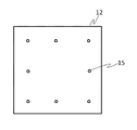
- FIG. 2 is a schematic diagram of the lower surface of the upper stage 12 and shows an example of the arrangement of the suction holes 15.
- a vacuum pump, a vacuum ejector, or the like can be used as the suction unit 14.
- a press unit 13 is connected to the upper part of the upper stage 12 for bonding the upper translucent hard substrate 25 while pressing the upper translucent hard substrate 25 against the lower translucent hard substrate 24.
- the press unit 13 has an elevating cylinder (not shown) that can move the upper stage 12 in the Z direction (vertical direction).
- the pressurizing force, moving speed, pressurizing time, and height are controlled by a servo motor. can do.
- the lower stage 17 holds the lower translucent hard substrate 24 and receives pressure from the upper stage 12 during pressing.
- the lower stage 17 is made of an ultraviolet light transmissive material. Examples of the material include transparent plastics such as quartz glass, magnesium fluoride, calcium fluoride, and methacrylic resin.
- the lower stage 17 can be moved in the X axis direction, the Y axis direction, and the ⁇ axis direction by the lower stage moving means 18.
- the lower stage moving means 18 includes a ⁇ table that enables a horizontal turning movement, and an X table and a Y table that enable a horizontal movement. These tables are driven by a motor.
- a motor-driven side clamp 19 that is movable in the X-axis direction and the Y-axis direction for positioning the translucent hard substrate placed thereon is provided on the upper surface of the lower stage 17.
- the lower stage moving means 18 is disposed at a position that does not hinder the path of ultraviolet rays irradiated from below.
- a positioning stopper for placing the translucent hard substrate at a predetermined position may be provided on the upper surface of the lower stage 17.
- the translucent hard substrate is manually placed at a position where the translucent hard substrate is fixed by the stopper.
- the lower translucent hard substrate 24 can also be held by vacuum suction.
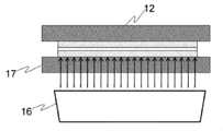
- an ultraviolet irradiation unit 16 for irradiating the lower surface of the lower translucent hard substrate 24 with ultraviolet rays for curing the adhesive is installed.
- the ultraviolet irradiation unit 16 is provided with a reflecting plate 16a in order to uniformly illuminate the entire lower translucent hard substrate 24 held by the lower stage 17.
- the ultraviolet irradiation unit 16 can be provided with a cooling mechanism for suppressing curing distortion.
- the cooling mechanism include a cold mirror, a cold filter, and a cooling fan. Control of the time for irradiating the light-transmitting hard substrate with ultraviolet rays is performed by opening and closing the shutter.
- the irradiation light is an irradiation amount necessary to cure the fixing agent, and is generally 30 to 4000 mJ / cm 2 , typically 100 to 3000 mJ / cm 2 , as measured by an integrating illuminometer using a 365 nm light receiver. 2 , more typically 300 to 2500 mJ / cm 2 , preferably 1000 to 2000 mJ / cm 2 .
- the irradiation time is generally 0.1 to 120 seconds, typically 1 to 30 seconds, more typically about 10 to 20 seconds.
- the lower substrate coating unit 20 includes a photo-curing adhesive dispenser 20a and a motor-driven robot 20b connected to the dispenser 20a and movable in the X-axis, Y-axis, and Z-axis directions.
- the fixing agent can be applied to the upper surface of the optical hard substrate 24 in an arbitrary pattern.
- the fixing agent is packed in a syringe and is automatically discharged in a fixed amount.
- the coating amount is controlled by a digital pressure gauge and a coating speed.
- the upper substrate coating unit 21 automatically coats the photocurable adhesive toward the lower surface of the upper translucent hard substrate 25 in a state where the upper translucent hard substrate 25 is held by the upper stage 12. To do.
- the application amount is controlled by a pressure gauge and application time.
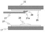
- the upper substrate coating unit 21 is provided with a motor-driven robot 21b having a rotation shaft that can rotate in the horizontal direction beside the upper and lower stages, and the tip rotary nozzle 21a is located near the center of the upper stage 12 during coating.
- the fixing agent is applied from the tip of the nozzle 21a. When the application is completed, it is stored beside the upper and lower stages so as not to interfere with the bonding of the translucent hard substrate.
- the imaging unit 22 has alignment marks for alignment provided on the respective surfaces of the upper light-transmitting hard substrate 25 and the lower light-transmitting hard substrate 24 attached at two positions above and below the tip of the arm. An image is taken with the digital camera 22a.
- the electrical unit 23 detects a relative positional shift state between the upper translucent hard substrate 25 and the lower translucent hard substrate 24 based on the captured image information. Based on the detection result, the position of the lower stage 17 is finely adjusted by the lower stage moving means 18 in the X-axis direction, the Y-axis direction, and the ⁇ -axis direction, and an operation for correcting the positional deviation is executed. After correcting the positional deviation, the two light-transmitting hard substrates are bonded together.
- a camera an analog camera can be used in addition to a digital camera using a CCD or CMOS as an image sensor, but a digital camera is preferable from the viewpoint of high resolution.
- the image pickup unit 22 is provided with moving means 22b driven by motors in the X-axis and Y-axis directions, and at the time of image pickup, the digital camera 22a moves to a predetermined position where the alignment mark enters the visual field. When the imaging is completed, the digital camera 22a moves so as not to obstruct the pasting of the translucent hard substrates.
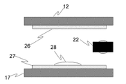
- the first translucent hard substrate 26 is placed on the lower stage 17 and fixed to a predetermined position by a side clamp 19 (not shown) (FIG. 3). Placement on the lower stage 17 of the light-transmitting hard substrate 26 can be performed manually, but a large number of light-transmitting hard substrates 26 are stored in a dedicated cassette and automatically placed on the lower stage 17. It may be placed.
- substrate 26 mounted is moved just under the upper stage 12 by the lower stage moving means 18 (not shown) (FIG. 4).
- the upper stage 12 is lowered by the press unit 13.
- the translucent hard substrate 26 is vacuum-sucked by the suction force from the suction hole 15 (not shown) (FIG. 5).
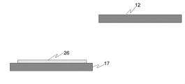
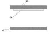
- the adsorbed translucent hard substrate 26 rises with the upper stage 12 while being held, and waits for the second substrate (FIG. 6).
- the second translucent hard substrate 27 is placed on the lower stage 17 and fixed to a predetermined position by a side clamp 19 (not shown) (FIG. 7).
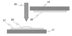
- the fixing agent 28 is applied in a predetermined pattern from the lower substrate coating unit 20 (FIG. 8).
- the alignment mark is imaged by a camera attached to the arm tip of the imaging unit 22. Then, the position of the lower stage 17 is finely adjusted in accordance with the imaging result, and the positions of both translucent hard substrates (26, 27) are adjusted (FIG. 9).
- the nozzle 21a attached to the arm tip of the upper substrate coating unit 21 moves to the vicinity of the center of the first substrate 26 held by the upper stage 12, and the fixing agent 29 is transferred from the nozzle 21a. It is applied to the lower surface of the first translucent hard substrate 26 (FIG. 10).
- the adhesive (28, 29) is applied to the upper and lower translucent hard substrates (26, 27)
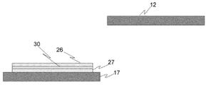
- the upper stage 12 is lowered by the press unit 13 and the two translucent hard substrates (26, 27) are applied.
- the adhesive (28, 29) sandwiched between the upper and lower light-transmitting hard substrates spreads over the entire surface of the light-transmitting hard substrate.
- steps (1) to (10) are performed using the translucent hard substrate laminating apparatus shown in FIG.
- the fixing agent softened into a film and separated into each plate product.
- the following plate glass was used as a translucent hard substrate.
- the plate glass used was a plate glass provided with a plating pattern with dimensions of 530 mm wide ⁇ 420 mm long ⁇ 0.7 mm thick.
- the photocurable fixing agent (I) was prepared by mixing the following components (A) to (E).
- UV-3000B urethane acrylate, hereinafter abbreviated as “UV-3000B”, weight average molecular weight 15000
- UV-3000B dicyclopentanyl diacrylate (Japan) “KAYARADR-684” manufactured by Kayaku Co., Ltd., hereinafter abbreviated as “R-684”
- R-684 dicyclopentanyl diacrylate
- B monofunctional (meth) acrylate, 45 parts by mass of 2- (1,2-cyclohexacarboximide) ethyl acrylate (“Aronix M-140” manufactured by Toagosei Co., Ltd., hereinafter abbreviated as “M-140”); 25 parts by mass of phenol ethylene oxide 2 mol modified acrylate (“Aronix M-101A” manufactured by Toa Gosei Co., Ltd.)
- C 10 parts by mass of benzyldi
- step (3) 40 g of the sticking agent (I) was applied to both bonded surfaces of the plate glass.
- the pressure at the time of bonding was 20 g / cm 2 .
- the UV irradiation amount is 160 mJ / cm 2 (measured by an integrated illuminometer using a 365 nm light receiver), and 20 g / cm 2.
- the UV irradiation time was set to 2 seconds and temporarily fixed.
- the UV irradiation amount is 2000 mJ / cm 2 (measured by an integrating illuminometer with a 365 nm light receiver)
- the irradiation time was 20 seconds.
- the above procedure was repeated to produce a plate glass laminate comprising 12 plate glasses using the sticking agent (I) as the sticking agent.
- a disk cutter diamond disk was used and divided into a rectangular parallelepiped shape (width 100 mm ⁇ length 55 mm ⁇ thickness 9.6 mm).
- step (9) grinding was performed with a rotating grindstone, drilling with an ultrasonic vibration drill, and end surface processing with a rotating brush were sequentially performed for shape processing.
- step (10) the plate glass laminate was immersed in 85 ° C. warm water and peeled off.
- Adhesive (II) The following components (A) to (E) were mixed to prepare a photocurable adhesive (II).
- UV-3000B urethane acrylate, hereinafter abbreviated as “UV-3000B”, weight average molecular weight 15000
- dicyclopentanyl diacrylate Japan
- KYAARADR-684 a polyfunctional (meth) acrylate
- R-684 a polyfunctional (meth) acrylate
- B As monofunctional (meth) acrylate, 35 parts by mass of 2-hydroxy-3-phenoxypropyl (meth) acrylate (“Aronix M-5700” manufactured by Toa Gosei Co., Ltd., hereinafter abbreviated as “M-5700”), phenol ethylene 20 parts by mass of oxide 2 mol modified acrylate (“Aronix M-101A” manufactured by Toa Gosei Co., Ltd.)
- C 10 parts by mass of benzyldimethyl ketal (“IRGACURE651” manufactured by BASF), hereinafter abbre
- Fixing agent (III) The following components (A) to (G) were mixed to prepare a photocurable fixing agent (III).
- UV-3000B urethane acrylate, hereinafter abbreviated as “UV-3000B”, weight average molecular weight 15000
- UV-3000B dicyclopenta Nil diacrylate
- R-684 dicyclopenta Nil diacrylate
- M-140 2- (1,2-cyclohexacarboximide
- M-140 phenol ethylene oxide 2 mol modified acrylate
- UV-3000B urethane acrylate, hereinafter abbreviated as “UV-3000B", weight average molecular weight 15000) 15 parts by mass, dicyclopentanyl diacrylate (“KAYARADR-684" manufactured by Nippon Kayaku Co., Ltd.), hereinafter “R- 684 ”)) 15 parts by mass
- B As monofunctional (meth) acrylate, 45 parts by mass of 2- (1,2-cyclohexacarboximide) ethyl acrylate (“Aronix M-140” manufactured by Toagosei Co., Ltd., hereinafter abbreviated as “M-140”); 25 parts by mass of phenol ethylene oxide 2 mol modified acrylate (“Aronix M-101A” manufactured by Toa Go
- the physical properties of the sticking agent (I), the sticking agent (II) and the sticking agent (III) are shown in Table 1.
- the evaluation method is as follows. For the fixing agent (III), the first agent and the second agent were weighed and mixed in an equal amount and evaluated.
- Tensile shear adhesive strength Measured according to JISK 6850. Specifically, heat-resistant Pyrex (registered trademark) glass (25 mm ⁇ 25 mm ⁇ 2.0 mm) was used as the adherend. Two heat-resistant Pyrex (registered trademark) glasses are bonded to each other with a bonding agent having a diameter of 8 mm, and a fusion device using an electrodeless discharge lamp is used. Curing was performed under the condition of cm 2 to prepare a tensile shear bond strength test piece. The prepared test piece was measured for tensile shear bond strength at a tensile rate of 10 mm / min in an environment of a temperature of 23 ° C.
- the adhesion test piece obtained by cutting only the heat-resistant Pyrex (registered trademark) glass part was immersed in hot water at 80 ° C. and peeled off. Also, 10 pieces of the peeled test specimens were taken out at random, and each piece on the back surface (the surface temporarily fixed with an adhesive) of the test specimen was observed using an optical microscope, and the glass was missing. The maximum width (distance from the ridge line in the plane direction parallel to the glass back surface) was measured, and the average value and standard deviation were obtained.
Landscapes
- Chemical & Material Sciences (AREA)
- Organic Chemistry (AREA)
- Engineering & Computer Science (AREA)
- Physics & Mathematics (AREA)
- Chemical Kinetics & Catalysis (AREA)
- Materials Engineering (AREA)
- Life Sciences & Earth Sciences (AREA)
- Nonlinear Science (AREA)
- Health & Medical Sciences (AREA)
- Medicinal Chemistry (AREA)
- Polymers & Plastics (AREA)
- Optics & Photonics (AREA)
- General Physics & Mathematics (AREA)
- Crystallography & Structural Chemistry (AREA)
- Manufacturing & Machinery (AREA)
- Wood Science & Technology (AREA)
- Ceramic Engineering (AREA)
- General Chemical & Material Sciences (AREA)
- Geochemistry & Mineralogy (AREA)
- Laminated Bodies (AREA)
- Joining Of Glass To Other Materials (AREA)
- Liquid Crystal (AREA)
- Adhesives Or Adhesive Processes (AREA)
- Lining Or Joining Of Plastics Or The Like (AREA)
Abstract
Description
このため、環境汚染を発生させることなく固着剤の回収及び処理が容易となる。」(段落0007)ことが記載されている。
1)第一の透光性硬質基板を準備する工程と、
2)第二の透光性硬質基板を準備する工程と、
3)第一の透光性硬質基板の第一の面及び/又は第二の透光性硬質基板の第一の面に、(A)多官能(メタ)アクリレート、(B)単官能(メタ)アクリレート、及び(C)光重合開始剤を含有する光硬化性の固着剤を塗布する工程と、
4)第一の透光性硬質基板の第一の面と第二の透光性硬質基板の第一の面とを予め定めた面方向の位置関係で両面が平行となるように対向させる工程と、
5)前記位置関係を維持しながら、第一の透光性硬質基板の第一の面と第二の透光性硬質基板の第一の面に所定の圧力を印加して、両透光性硬質基板を貼り合わせる工程と、
6)所定の圧力を印可しながら両透光性硬質基板に挟まれて広がっている固着剤全体を硬化するための光を照射して、透光性硬質基板積層体を形成する工程と、
7)前記透光性硬質基板積層体を第一の透光性硬質基板に見立てて、工程1)~6)を少なくとも1回繰り返し、少なくとも3枚の透光性硬質基板が貼り合わせられた透光性硬質基板積層体を形成する工程と
を含む透光性硬質基板積層体の製造方法である。
5’)工程6)よりも低エネルギーの光を両透光性硬質基板に挟まれて広がっている固着剤の全体もしくは一部に照射して、仮留め透光性硬質基板積層体を形成する工程、
を更に含んでも良い。
8)上記の透光性硬質基板積層体の製造方法を用いて得られた透光性硬質基板積層体を厚み方向に分割し、所望の数の分割された透光性硬質基板積層体を形成する工程と、
9)分割された透光性硬質基板積層体それぞれに対して所望の形状加工を行う工程と、
10)形状加工後の透光性硬質基板積層体を加熱することで貼り合わせられていた透光性硬質基板同士を剥離し、複数の板状製品を形成する工程と、
を含む板状製品の製造方法である。
上側の透光性硬質基板を真空吸着するための吸引孔を有し、上側の透光性硬質基板を保持するための上側ステージと、
上側ステージをZ軸方向に移動させることのできるプレスユニットと、
前記吸引孔に吸引力を与える吸引ユニットと、
下側の透光性硬質基板を保持するための下側ステージと、
下側ステージをX軸方向、Y軸方向及びθ軸方向に移動させる手段と、
上側の透光性硬質基板の下面及び下側の透光性硬質基板の上面のいずれか又は両方に、(A)多官能(メタ)アクリレート、(B)単官能(メタ)アクリレート、及び(C)光重合開始剤を含有する光硬化性の固着剤を塗布するための手段と、
下側の透光性硬質基板全面に向かって下方から光を照射するための光照射部と、
を備えた透光性硬質基板貼り合わせ装置である。
固着剤が粒状物質を含有することで、固着剤の厚みを一定にすることができるため、加工精度が向上する。また、固着剤成分と粒状物質の線膨張係数の違いにより、後に剥離するときの剥離性も向上する。
本発明に係る透光性硬質基板貼り合わせ装置の更に別の一実施形態においては、前記固着剤は二剤型の組成物であり、第一剤に少なくとも(F)有機過酸化物を含有し、第二剤に少なくとも(G)分解促進剤を含有する。
本発明に係る透光性硬質基板積層体の製造方法の第一実施形態においては、
1)第一の透光性硬質基板を準備する工程と、
2)第二の透光性硬質基板を準備する工程と、
3)第一の透光性硬質基板の第一の面及び/又は第二の透光性硬質基板の第一の面に、(A)多官能(メタ)アクリレート、(B)単官能(メタ)アクリレート、及び(C)光重合開始剤を含有する光硬化性の固着剤を塗布する工程と、
4)第一の透光性硬質基板の第一の面と第二の透光性硬質基板の第一の面とを予め定めた面方向の位置関係で両面が平行となるように対向させる工程と、
5)前記位置関係を維持しながら、第一の透光性硬質基板の第一の面と第二の透光性硬質基板の第一の面に所定の圧力を印加して、両透光性硬質基板を貼り合わせる工程と、
6)前記圧力を維持したまま、両透光性硬質基板に挟まれて広がっている固着剤全体を硬化するための光を照射して、透光性硬質基板積層体を形成する工程と、
7)前記透光性硬質基板積層体を第一の透光性硬質基板に見立てて、工程1)~6)を少なくとも1回繰り返し、少なくとも3枚の透光性硬質基板が貼り合わせられた透光性硬質基板積層体を形成する工程と、
が実行される。
剥離性と寸法精度の観点からより好ましい平均粒径(D50)は35μm~150μmであり、更に好ましくは50μm~120μmである。粒径分布は、レーザー回折式粒度分布測定装置により測定される。
有機過酸化物としてハイドロパーオキサイド類やケトンパーオキサイド類のものを使用する場合、分解促進剤としては、有機酸金属塩や有機金属キレート等が挙げられる。有機酸金属塩や有機金属キレートとしては、例えば、ナフテン酸コバルト、ナフテン酸銅、ナフテン酸マンガン、オクテン酸コバルト、オクテン酸銅、オクテン酸マンガン、オクチル酸コバルト、銅アセチルアセトネート、チタンアセチルアセトネート、マンガンアセチルアセトネート、クロムアセチルアセトネート、鉄アセチルアセトネート、バナジルアセチルアセトネート及びコバルトアセチルアセトネート等が挙げられる。これらの中では、オクチル酸コバルト及び/又はバナジルアセチルアセトネートが好ましく、オクチル酸コバルトが最も好ましい。その他の分解促進剤としては、チオ尿素誘導体類、メルカプトベンゾイミダゾール、アミン類等が挙げられる。これらの(D)分解促進剤は、1種又は2種以上を使用することができる。
本発明に係る透光性硬質基板積層体の製造方法においては、複数の工程を並行して実施してもよい。本発明に係る透光性硬質基板積層体の製造方法の一実施形態においては、同時に透光性硬質基板積層体の作製作業を行い、一つの工程を終えた後に続いて、次の工程に製造中の透光性硬質基板を移行し一つの工程を連続して続けることにより、複数の透光性硬質基板積層体を同時に並行して製造可能になり、かつ、効率的に製造可能にある。例えば5つの透光性硬質基板積層体を同時に製造するには、工程1)~3)、工程4)、工程5)、工程5’)、工程6)工程のそれぞれの工程で1つずつ透光性硬質基板の作製を同時に並行して行い、それぞれの工程が終わった後、続いて次の工程に移行し、一つの工程としては連続的に続けることで効率的に透光性硬質基板を作製可能となる。
上記の透光性硬質基板積層体の製造方法によって得られた透光性硬質基板積層体から板状製品を製造することができる。
本発明に係る透光性硬質基板貼り合わせ装置の例について説明する。本発明に係る透光性硬質基板貼り合わせ装置は、基板の貼り合わせと接着を同時に実施するために使用される。本発明を使用して得られた透光性硬質基板積層体に更に基板を貼り合わせることで、多数の透光性硬質基板からなる透光性硬質基板積層体を製造することができる。この透光性硬質基板積層体は厚み方向に分割し、所望の数の分割された透光性硬質基板積層体を形成することができる。分割された透光性硬質基板積層体それぞれに対して所望の形状加工を行い、形状加工後の透光性硬質基板積層体を加熱(例:温水浸漬)することで貼り合わせられていた透光性硬質基板同士を剥離し、複数の板状製品を形成することができる。
上側及び下側の透光性硬質基板(26、27)に固着剤(28、29)を塗布後、上側ステージ12をプレスユニット13により降下させて二枚の透光性硬質基板(26、27)を加圧して貼り合わせると、上側及び下側の透光性硬質基板に挟まれた固着剤(28、29)は加圧により透光性硬質基板全面に広がる。加圧状態を維持しながら、紫外線照射ユニット16から紫外線が固着剤に向けて照射される(図11)。これにより、固着剤が硬化して二枚の透光性硬質基板(26、27)が接着する。
光硬化性の固着剤(I)は、下記の(A)~(E)の成分を混合して作製した。
(B)単官能(メタ)アクリレートとして、2-(1,2-シクロヘキサカルボキシイミド)エチルアクリレート(東亜合成社製「アロニックスM-140」、以下「M-140」と略す)45質量部、フェノールエチレンオキサイド2モル変性アクリレート(東亜合成社製「アロニックスM-101A」)25質量部、
(C)光重合開始剤としてベンジルジメチルケタール(BASF社製「IRGACURE651」)、以下「BDK」と略す)10質量部、
(D)粒状物質として平均粒径100μmの球状架橋ポリスチレン粒子(ガンツ化成社製「GS-100S」)1質量部、
(E)重合禁止剤として2,2-メチレン-ビス(4-メチル-6-ターシャリーブチルフェノール)(住友化学社製「スミライザーMDP-S」、以下「MDP」と略す)0.1質量部
(B)単官能(メタ)アクリレートとして、2-ヒドロキシ-3-フェノキシプロピル(メタ)アクリレート(東亜合成社製「アロニックスM-5700」、以下「M-5700」と略す)35質量部、フェノールエチレンオキサイド2モル変性アクリレート(東亜合成社製「アロニックスM-101A」)20質量部、
(C)光重合開始剤としてベンジルジメチルケタール(BASF社製「IRGACURE651」)、以下「BDK」と略す)10質量部、
(D)粒状物質として平均粒径100μmの球状架橋ポリスチレン粒子(ガンツ化成社製「GS-100S」)1質量部、
(E)重合禁止剤として2,2-メチレン-ビス(4-メチル-6-ターシャリーブチルフェノール)(住友化学社製「スミライザーMDP-S」、以下「MDP」と略す)0.1質量部
(B)単官能(メタ)アクリレートとして、2-(1,2-シクロヘキサカルボキシイミド)エチルアクリレート(東亜合成社製「アロニックスM-140」、以下「M-140」と略す)45質量部、フェノールエチレンオキサイド2モル変性アクリレート(東亜合成社製「アロニックスM-101A」)25質量部、
(C)光重合開始剤としてベンジルジメチルケタール(BASF社製「IRGACURE651」)、以下「BDK」と略す)10質量部、
(D)粒状物質として平均粒径100μmの球状架橋ポリスチレン粒子(ガンツ化成社製「GS-100S」)1質量部、
(E)重合禁止剤として2,2-メチレン-ビス(4-メチル-6-ターシャリーブチルフェノール)(住友化学社製「スミライザーMDP-S」、以下「MDP」と略す)0.1質量部
(F)有機過酸化物としてクメンハイドロパーオキサイド(日本油脂社製「パークミルH」、以下「CHP」と略す)2質量部
<第二剤>(A)多官能(メタ)アクリレートとして、日本合成社製「UV-3000B」(ウレタンアクリレート、以下「UV-3000B」と略す、重量平均分子量15000)15質量部、ジシクロペンタニルジアクリレート(日本化薬社製「KAYARADR-684」、以下「R-684」と略す)15質量部、
(B)単官能(メタ)アクリレートとして、2-(1,2-シクロヘキサカルボキシイミド)エチルアクリレート(東亜合成社製「アロニックスM-140」、以下「M-140」と略す)45質量部、フェノールエチレンオキサイド2モル変性アクリレート(東亜合成社製「アロニックスM-101A」)25質量部、
(C)光重合開始剤としてベンジルジメチルケタール(BASF社製「IRGACURE651」)、以下「BDK」と略す)10質量部、
(D)粒状物質として平均粒径100μmの球状架橋ポリスチレン粒子(ガンツ化成社製「GS-100S」)1質量部、
(E)重合禁止剤として2,2-メチレン-ビス(4-メチル-6-ターシャリーブチルフェノール)(住友化学社製「スミライザーMDP-S」、以下「MDP」と略す)0.1質量部
(G)分解促進剤としてオクチル酸コバルト(神東塗料株式会社製「オクチル酸コバルト」、以下「Oct-Co」と略す)2質量部
(1)引張せん断接着強さ(接着強さ):JISK 6850に従い測定した。具体的には被着材として耐熱パイレックス(登録商標)ガラス(25mm×25mm×2.0mm)を用いた。接着部位を直径8mmとして、作製した固着剤にて、2枚の耐熱パイレックス(登録商標)ガラスを貼り合わせ、無電極放電ランプを使用したフュージョン社製硬化装置により、365nmの波長の積算光量2000mJ/cm2の条件にて硬化させ、引張せん断接着強さ試験片を作製した。作製した試験片は、万能試験機を使用して、温度23℃、湿度50%の環境下、引張速度10mm/minで引張せん断接着強さを測定した。
(2)剥離試験(80℃温水剥離時間):上記耐熱パイレックス(登録商標)ガラスに固着剤を塗布し、支持体として青板ガラス(150mm×150mm×厚さ1.7mm)に貼り合わせた以外は上記と同様な条件で作製した固着剤を硬化させ、剥離試験体を作製した。得られた試験体を、温水(80℃)に浸漬し、耐熱パイレックス(登録商標)ガラスが剥離する時間を測定した。
(3)切断試験片10個の裏面片の欠けの最大幅、切断試験片10個の裏面片の欠けの最大幅の標準偏差:固着剤(I)と固着剤(II)と固着剤(III)をそれぞれ用いて、縦150mm×横150mm×厚さ2mmの板状耐熱パイレックス(登録商標)ガラスと、剥離試験で用いた青板ガラス(ダミーガラスとして使用)とを、上記と同様に接着硬化させた。この接着試験体の耐熱パイレックス(登録商標)ガラス部分のみをダイシング装置を使用して10mm角に切断した。切断中に耐熱パイレックス(登録商標)ガラスの脱落は発生せず、良好な加工性を示した。耐熱パイレックス(登録商標)ガラス部分のみを切断した接着試験体を80℃の温水に浸漬して剥離した。また、その剥離した切断試験片を無作為に10個取り出し、その切断試験片の裏面(固着剤で仮固定した面)の各片を、光学顕微鏡を用いて観察し、ガラスが欠けている箇所の最大幅(ガラス裏面に平行な面方向への稜線からの距離)を測定し、その平均値と標準偏差を求めた。

11 架台
12 上側ステージ
13 プレスユニット
14 吸引ユニット
15 吸引孔
16 紫外線照射ユニット
17 下側ステージ
18 下側ステージ移動手段
19 サイドクランプ
20 下側基板用塗布ユニット
21 上側基板用塗布ユニット
22 撮像ユニット
23 電装ユニット
24 下側基板
25 上側基板
31 透光性硬質基板
32 固着剤
33 回転ブラシ
Claims (33)
- 1)第一の透光性硬質基板を準備する工程と、
2)第二の透光性硬質基板を準備する工程と、
3)第一の透光性硬質基板の第一の面及び/又は第二の透光性硬質基板の第一の面に、(A)多官能(メタ)アクリレート、(B)単官能(メタ)アクリレート、及び(C)光重合開始剤を含有する光硬化性の固着剤を塗布する工程と、
4)第一の透光性硬質基板の第一の面と第二の透光性硬質基板の第一の面とを予め定めた面方向の位置関係で両面が平行となるように対向させる工程と、
5)前記位置関係を維持しながら、第一の透光性硬質基板の第一の面と第二の透光性硬質基板の第一の面に所定の圧力を印加して、両透光性硬質基板を貼り合わせる工程と、
6)所定の圧力を印可しながら、両透光性硬質基板に挟まれて広がっている固着剤全体を硬化するための光を照射して、透光性硬質基板積層体を形成する工程と、
7)前記透光性硬質基板積層体を第一の透光性硬質基板に見立てて、工程1)~6)を少なくとも1回繰り返し、少なくとも3枚の透光性硬質基板が貼り合わせられた透光性硬質基板積層体を形成する工程と
を含む透光性硬質基板積層体の製造方法。 - 工程6)は、第二の透光性硬質基板の表面に向かって光を照射することにより行う請求項1記載の透光性硬質基板積層体の製造方法。
- 工程5)と工程6)の間に、
5’)工程6)よりも低エネルギーの光を両透光性硬質基板に挟まれて広がっている固着剤の全体もしくは一部に照射して、仮留め透光性硬質基板積層体を形成する工程を実施する請求項1又は2に記載の透光性硬質基板積層体の製造方法。 - 各透光性硬質基板の表面に位置合わせのための目印が付されており、工程4)はこれを撮像装置で撮像しながら位置調整を行うことを含む請求項1~3の何れか一項に記載の透光性硬質基板積層体の製造方法。
- 各透光性硬質基板の表面には透光性硬質基板製品の機能の一つを奏するための所定の印刷パターン及び/又はめっきパターンが付されている請求項1~4の何れか一項に記載の透光性硬質基板積層体の製造方法。
- 前記固着剤は粒状物質を含有する請求項1~5何れか一項記載の透光性硬質基板積層体の製造方法。
- 工程6)における光の照射量は、365nmの受光器を使用した積算照度計で測定して、30mJ/cm2~4000mJ/cm2の範囲である請求項1~6何れか一項記載の透光性硬質基板積層体の製造方法。
- 透光性硬質基板が板ガラスである請求項1~7何れか一項記載の透光性硬質基板積層体の製造方法。
- 8)請求項1~8何れか一項記載の方法を用いて得られた透光性硬質基板積層体を厚み方向に分割し、所望の数の分割された透光性硬質基板積層体を形成する工程と、
9)分割された透光性硬質基板積層体それぞれに対して所望の形状加工を行う工程と、
10)形状加工後の透光性硬質基板積層体を加熱することで貼り合わせられていた透光性硬質基板同士を剥離し、複数の板状製品を形成する工程と、
を含む板状製品の製造方法。 - 工程8)と工程9)の間に、分割された透光性硬質基板積層体を、各透光性硬質基板に挟まれた固着剤外縁の露出部分の接着力を低下させるのに必要な温度及び時間条件で、剥離剤に接触させる工程を更に含む請求項9記載の板状製品の製造方法。
- 剥離剤が溶剤、酸化剤、及び界面活性剤から選択される一種又は二種以上を含有する請求項10記載の板状製品の製造方法。
- 剥離剤が水、アルコール類、酸化剤、及び界面活性剤から選択される一種又は二種以上を含有する請求項10記載の板状製品の製造方法。
- 剥離剤が水とアルコール類と界面活性剤を30~50:30~50:5~20の質量比で含有する請求項10記載の板状製品の製造方法。
- 剥離剤がベンジルアルコールを含有する請求項10~13何れか一項記載の板状製品の製造方法。
- 剥離剤がアニオン系界面活性剤を含有する請求項10~14何れか一項記載の板状製品の製造方法。
- 剥離剤がスルホン酸型界面活性剤を含有する請求項15記載の板状製品の製造方法。
- 剥離剤の液温が50℃以下であり、剥離剤に接触させる時間が1~20分である請求項10~16何れか一項記載の板状製品の製造方法。
- (A)多官能(メタ)アクリレートが、多官能(メタ)アクリレートオリゴマー/ポリマー及び/又は2官能(メタ)アクリレートモノマーを含有する請求項1~8何れか一項記載の透光性硬質基板積層体の製造方法。
- (B)単官能(メタ)アクリレートが、フェノールエチレンオキサイド2モル変性(メタ)アクリレート、2-(1,2-シクロヘキサカルボキシイミド)エチル(メタ)アクリレート及び2-ヒドロキシ-3-フェノキシプロピル(メタ)アクリレートからなる群のうちの1種以上を含有する請求項1~8、18何れか一項記載の透光性硬質基板積層体の製造方法。
- (B)単官能(メタ)アクリレートが、フェノールエチレンオキサイド2モル変性(メタ)アクリレート及び2-(1,2-シクロヘキサカルボキシイミド)エチル(メタ)アクリレートを含有する請求項1~8、18何れか一項記載の透光性硬質基板積層体の製造方法。
- (B)単官能(メタ)アクリレートが、フェノールエチレンオキサイド2モル変性(メタ)アクリレート及び2-ヒドロキシ-3-フェノキシプロピル(メタ)アクリレートを含有する請求項1~8、18何れか一項記載の透光性硬質基板積層体の製造方法。
- 前記固着剤が二剤型の組成物であり、第一剤に少なくとも(F)有機過酸化物を含有し、第二剤に少なくとも(G)分解促進剤を含有する請求項1~8、18~21何れか一項記載の透光性硬質基板積層体の製造方法。
- 複数の工程を並行して実施する請求項1~8、18~22何れか一項記載の透光性硬質基板積層体の製造方法。
- 上側の透光性硬質基板を真空吸着するための吸引孔を有し、上側の透光性硬質基板を保持するための上側ステージと、
上側ステージをZ軸方向に移動させることのできるプレスユニットと、
前記吸引孔に吸引力を与える吸引ユニットと、
下側の透光性硬質基板を保持するための下側ステージと、
下側ステージをX軸方向、Y軸方向及びθ軸方向に移動させる手段と、
上側の透光性硬質基板の下面及び下側の透光性硬質基板の上面のいずれか又は両方に、(A)多官能(メタ)アクリレート、(B)単官能(メタ)アクリレート、及び(C)光重合開始剤を含有する光硬化性の固着剤を塗布するための手段と、
下側の透光性硬質基板全面に向かって下方から光を照射するための光照射部と、
を備えた透光性硬質基板貼り合わせ装置。 - 上側及び下側の透光性硬質基板の表面に設けられたアライメントマークを撮像する撮像ユニットと、撮像結果に基づいて上側及び下側の表面に設けられたアライメントマークの位置ずれ度合いを検出する画像処理ユニットと、検出された位置ずれ度合いに基づいて前記下側ステージ移動手段を制御する制御ユニットとを更に備えた請求項24記載の透光性硬質基板貼り合わせ装置。
- 上側ステージ及び/又は下側ステージに保持される透光性硬質基板は2枚以上の透光性硬質基板の積層体である請求項24又は25記載の透光性硬質基板貼り合わせ装置。
- 固着剤を塗布するための手段は、粒状物質を含有する固着剤を塗布する請求項24~26何れか一項記載の透光性硬質基板貼り合わせ装置。
- 透光性硬質基板が板ガラスである請求項24~27何れか一項記載の透光性硬質基板貼り合わせ装置。
- (A)多官能(メタ)アクリレートが、多官能(メタ)アクリレートオリゴマー/ポリマー及び/又は2官能(メタ)アクリレートモノマーを含有する請求項24~28何れか一項記載の透光性硬質基板貼り合わせ装置。
- (B)単官能(メタ)アクリレートが、フェノールエチレンオキサイド2モル変性(メタ)アクリレート、2-(1,2-シクロヘキサカルボキシイミド)エチル(メタ)アクリレート及び2-ヒドロキシ-3-フェノキシプロピル(メタ)アクリレートからなる群のうちの1種以上を含有する請求項24~29何れか一項記載の透光性硬質基板貼り合わせ装置。
- (B)単官能(メタ)アクリレートが、フェノールエチレンオキサイド2モル変性(メタ)アクリレート及び2-(1,2-シクロヘキサカルボキシイミド)エチル(メタ)アクリレートを含有する請求項24~30何れか一項記載の透光性硬質基板貼り合わせ装置。
- (B)単官能(メタ)アクリレートが、フェノールエチレンオキサイド2モル変性(メタ)アクリレート及び2-ヒドロキシ-3-フェノキシプロピル(メタ)アクリレートを含有する請求項24~31何れか一項記載の透光性硬質基板貼り合わせ装置。
- 前記固着剤は二剤型の組成物であり、第一剤に少なくとも(F)有機過酸化物を含有し、第二剤に少なくとも(G)分解促進剤を含有する請求項24~32何れか一項記載の透光性硬質基板貼り合わせ装置。
Priority Applications (6)
| Application Number | Priority Date | Filing Date | Title |
|---|---|---|---|
| PH1/2014/500145A PH12014500145A1 (en) | 2011-07-15 | 2012-07-13 | Method of manufacturing translucent rigid substrate laminate and translucent rigid substrate bonding apparatus |
| KR1020147000784A KR20140041720A (ko) | 2011-07-15 | 2012-07-13 | 투광성 경질 기판 적층체의 제조 방법 및 투광성 경질 기판 접합 장치 |
| US14/233,069 US9381727B2 (en) | 2011-07-15 | 2012-07-13 | Method of manufacturing translucent rigid substrate laminate and translucent rigid substrate bonding apparatus |
| HK14104855.0A HK1191610B (en) | 2011-07-15 | 2012-07-13 | Method for producing translucent rigid substrate laminate and device for pasting together translucent rigid substrates |
| JP2013524716A JP6050751B2 (ja) | 2011-07-15 | 2012-07-13 | 透光性硬質基板積層体の製造方法及び透光性硬質基板貼り合わせ装置 |
| CN201280035212.2A CN103648753B (zh) | 2011-07-15 | 2012-07-13 | 透光性硬质基板层叠体的制造方法及透光性硬质基板贴合装置 |
Applications Claiming Priority (2)
| Application Number | Priority Date | Filing Date | Title |
|---|---|---|---|
| JP2011-156250 | 2011-07-15 | ||
| JP2011156250 | 2011-07-15 |
Publications (1)
| Publication Number | Publication Date |
|---|---|
| WO2013011970A1 true WO2013011970A1 (ja) | 2013-01-24 |
Family
ID=47558147
Family Applications (1)
| Application Number | Title | Priority Date | Filing Date |
|---|---|---|---|
| PCT/JP2012/068021 Ceased WO2013011970A1 (ja) | 2011-07-15 | 2012-07-13 | 透光性硬質基板積層体の製造方法及び透光性硬質基板貼り合わせ装置 |
Country Status (7)
| Country | Link |
|---|---|
| US (1) | US9381727B2 (ja) |
| JP (1) | JP6050751B2 (ja) |
| KR (1) | KR20140041720A (ja) |
| CN (1) | CN103648753B (ja) |
| PH (1) | PH12014500145A1 (ja) |
| TW (1) | TWI541275B (ja) |
| WO (1) | WO2013011970A1 (ja) |
Cited By (7)
| Publication number | Priority date | Publication date | Assignee | Title |
|---|---|---|---|---|
| CN104045240A (zh) * | 2013-03-13 | 2014-09-17 | 电气化学工业株式会社 | 硬质基板层叠体的加工方法及紧固夹具 |
| WO2014174774A1 (ja) * | 2013-04-26 | 2014-10-30 | 昭和電工株式会社 | 貼り合せ方法 |
| JP2016204661A (ja) * | 2015-04-22 | 2016-12-08 | デンカ株式会社 | 組成物 |
| JP2017222124A (ja) * | 2016-06-17 | 2017-12-21 | 株式会社フジクラ | 樹脂材料の厚みの調整方法及びその調整装置 |
| WO2017217543A1 (ja) * | 2016-06-17 | 2017-12-21 | 株式会社フジクラ | アライメント方法及びアライメント装置 |
| JPWO2017217543A1 (ja) * | 2016-06-17 | 2019-02-28 | 株式会社フジクラ | アライメント方法及びアライメント装置 |
| JP2019520242A (ja) * | 2016-05-03 | 2019-07-18 | プレシジョン バルブ アンド オートメーション インコーポレイテッド | オプティカルボンディングのための自動接合シーケンスの決定 |
Families Citing this family (10)
| Publication number | Priority date | Publication date | Assignee | Title |
|---|---|---|---|---|
| CN103221211B (zh) * | 2010-11-22 | 2016-06-29 | 电化株式会社 | 平板的贴合夹具及平板层叠体的制造方法 |
| CN106104659A (zh) * | 2014-03-20 | 2016-11-09 | 芝浦机械电子装置株式会社 | 显示装置用构件的制造装置及显示装置用构件的制造方法 |
| RU2578669C1 (ru) * | 2014-10-14 | 2016-03-27 | Общество С Ограниченной Ответственностью "Центр Продвижения Высокотехнологичных Проектов "Новстрим" | Плазменное осветительное устройство с свч накачкой |
| US11332562B2 (en) * | 2016-10-06 | 2022-05-17 | Denka Company Limited | Composition |
| JP7066559B2 (ja) * | 2018-07-13 | 2022-05-13 | 東京エレクトロン株式会社 | 接合装置および接合方法 |
| CN113795906B (zh) * | 2019-05-08 | 2025-05-02 | 东京毅力科创株式会社 | 接合装置、接合系统以及接合方法 |
| JP7488738B2 (ja) * | 2020-09-18 | 2024-05-22 | 日機装株式会社 | 真空積層装置及び積層体の製造方法 |
| CN113085159B (zh) * | 2021-05-18 | 2023-08-29 | 上汽通用五菱汽车股份有限公司 | 一种增强尾门内外板连接强度的表面处理设备及方法 |
| CN114609711B (zh) * | 2022-03-09 | 2023-07-18 | 业成科技(成都)有限公司 | 光学元件的制造方法、夹持装置、显示模组及电子设备 |
| CN115057233B (zh) * | 2022-06-09 | 2024-01-09 | 河北光兴半导体技术有限公司 | 一种掰断装置及掰断方法 |
Citations (6)
| Publication number | Priority date | Publication date | Assignee | Title |
|---|---|---|---|---|
| JPH1171553A (ja) * | 1997-08-28 | 1999-03-16 | Toagosei Co Ltd | 仮固定用光硬化性組成物及び物品の製造方法 |
| JP2000169166A (ja) * | 1998-11-30 | 2000-06-20 | Hoya Optics Kk | 板ガラス製品の製造方法 |
| JP2003270606A (ja) * | 2002-03-14 | 2003-09-25 | Shibaura Mechatronics Corp | 基板貼り合わせ装置および基板貼り合わせ方法 |
| WO2008018252A1 (en) * | 2006-08-10 | 2008-02-14 | Denki Kagaku Kogyo Kabushiki Kaisha | Adhesive composition and method for temporarily fixing member by using the same |
| WO2010010900A1 (ja) * | 2008-07-22 | 2010-01-28 | 電気化学工業株式会社 | 部材の仮固定・剥離方法及びそれに好適な仮固定用接着剤 |
| JP2010169830A (ja) * | 2009-01-21 | 2010-08-05 | Fujinon Corp | プリズムアセンブリの製造方法 |
Family Cites Families (16)
| Publication number | Priority date | Publication date | Assignee | Title |
|---|---|---|---|---|
| JPH0647486B2 (ja) * | 1986-09-01 | 1994-06-22 | オリンパス光学工業株式会社 | レンズの心出し保持方法 |
| US5624521A (en) * | 1993-09-21 | 1997-04-29 | Hed; P. Paul | Method of holding optical elements without deformation during their fabrication |
| US6004413A (en) * | 1995-12-19 | 1999-12-21 | Couttenier; Andre | Method for making a laminate and device for the application of this method |
| CN1306509C (zh) * | 1996-04-19 | 2007-03-21 | 松下电器产业株式会社 | 叠层式光盘制造方法及其装置 |
| JP2997918B2 (ja) | 1996-07-31 | 2000-01-11 | セイコー精機株式会社 | ロボットマウンタ及びコアマウント方法 |
| JP3536651B2 (ja) * | 1998-03-18 | 2004-06-14 | セイコーエプソン株式会社 | 基板接合装置、基板接合方法、および液晶装置の製造方法 |
| JP2000044292A (ja) | 1998-07-28 | 2000-02-15 | Nippon Sheet Glass Co Ltd | ガラスパネルのスペーサ固定方法及びガラスパネル |
| US6475292B1 (en) * | 2000-07-31 | 2002-11-05 | Shipley Company, L.L.C. | Photoresist stripping method |
| JP3742000B2 (ja) * | 2000-11-30 | 2006-02-01 | 富士通株式会社 | プレス装置 |
| JP3930284B2 (ja) * | 2000-12-18 | 2007-06-13 | 株式会社東芝 | 平面表示素子の製造方法 |
| US6627309B2 (en) * | 2001-05-08 | 2003-09-30 | 3M Innovative Properties Company | Adhesive detackification |
| JP4405323B2 (ja) | 2004-06-21 | 2010-01-27 | リンテック株式会社 | 積層シートおよびその製造方法 |
| JP4993613B2 (ja) | 2008-02-29 | 2012-08-08 | 株式会社ジャパンディスプレイイースト | 表示装置の製造方法 |
| JP2009256125A (ja) | 2008-04-15 | 2009-11-05 | Shoda Techtron Corp | 板ガラスの加工方法 |
| MY166265A (en) * | 2010-01-21 | 2018-06-22 | Denka Company Ltd | Method of manufacturing translucent rigid substrate laminate and translucent rigid substrate bonding apparatus |
| KR101824709B1 (ko) | 2010-01-21 | 2018-02-01 | 덴카 주식회사 | 투광성 경질 기판 적층체의 제조방법 및 투광성 경질 기판 라미네이팅 장치 |
-
2012
- 2012-07-13 JP JP2013524716A patent/JP6050751B2/ja not_active Expired - Fee Related
- 2012-07-13 PH PH1/2014/500145A patent/PH12014500145A1/en unknown
- 2012-07-13 CN CN201280035212.2A patent/CN103648753B/zh not_active Expired - Fee Related
- 2012-07-13 TW TW101125323A patent/TWI541275B/zh not_active IP Right Cessation
- 2012-07-13 KR KR1020147000784A patent/KR20140041720A/ko not_active Ceased
- 2012-07-13 US US14/233,069 patent/US9381727B2/en not_active Expired - Fee Related
- 2012-07-13 WO PCT/JP2012/068021 patent/WO2013011970A1/ja not_active Ceased
Patent Citations (6)
| Publication number | Priority date | Publication date | Assignee | Title |
|---|---|---|---|---|
| JPH1171553A (ja) * | 1997-08-28 | 1999-03-16 | Toagosei Co Ltd | 仮固定用光硬化性組成物及び物品の製造方法 |
| JP2000169166A (ja) * | 1998-11-30 | 2000-06-20 | Hoya Optics Kk | 板ガラス製品の製造方法 |
| JP2003270606A (ja) * | 2002-03-14 | 2003-09-25 | Shibaura Mechatronics Corp | 基板貼り合わせ装置および基板貼り合わせ方法 |
| WO2008018252A1 (en) * | 2006-08-10 | 2008-02-14 | Denki Kagaku Kogyo Kabushiki Kaisha | Adhesive composition and method for temporarily fixing member by using the same |
| WO2010010900A1 (ja) * | 2008-07-22 | 2010-01-28 | 電気化学工業株式会社 | 部材の仮固定・剥離方法及びそれに好適な仮固定用接着剤 |
| JP2010169830A (ja) * | 2009-01-21 | 2010-08-05 | Fujinon Corp | プリズムアセンブリの製造方法 |
Cited By (7)
| Publication number | Priority date | Publication date | Assignee | Title |
|---|---|---|---|---|
| CN104045240A (zh) * | 2013-03-13 | 2014-09-17 | 电气化学工业株式会社 | 硬质基板层叠体的加工方法及紧固夹具 |
| WO2014174774A1 (ja) * | 2013-04-26 | 2014-10-30 | 昭和電工株式会社 | 貼り合せ方法 |
| JP2016204661A (ja) * | 2015-04-22 | 2016-12-08 | デンカ株式会社 | 組成物 |
| JP2019520242A (ja) * | 2016-05-03 | 2019-07-18 | プレシジョン バルブ アンド オートメーション インコーポレイテッド | オプティカルボンディングのための自動接合シーケンスの決定 |
| JP2017222124A (ja) * | 2016-06-17 | 2017-12-21 | 株式会社フジクラ | 樹脂材料の厚みの調整方法及びその調整装置 |
| WO2017217543A1 (ja) * | 2016-06-17 | 2017-12-21 | 株式会社フジクラ | アライメント方法及びアライメント装置 |
| JPWO2017217543A1 (ja) * | 2016-06-17 | 2019-02-28 | 株式会社フジクラ | アライメント方法及びアライメント装置 |
Also Published As
| Publication number | Publication date |
|---|---|
| US20140158280A1 (en) | 2014-06-12 |
| TWI541275B (zh) | 2016-07-11 |
| PH12014500145A1 (en) | 2014-02-24 |
| TW201307452A (zh) | 2013-02-16 |
| CN103648753A (zh) | 2014-03-19 |
| CN103648753B (zh) | 2016-01-27 |
| US9381727B2 (en) | 2016-07-05 |
| JPWO2013011970A1 (ja) | 2015-02-23 |
| HK1191610A1 (zh) | 2014-08-01 |
| JP6050751B2 (ja) | 2016-12-21 |
| KR20140041720A (ko) | 2014-04-04 |
Similar Documents
| Publication | Publication Date | Title |
|---|---|---|
| JP6050751B2 (ja) | 透光性硬質基板積層体の製造方法及び透光性硬質基板貼り合わせ装置 | |
| JP5753099B2 (ja) | 透光性硬質基板積層体の製造方法及び透光性硬質基板貼り合わせ装置 | |
| JP6012601B2 (ja) | 透光性硬質基板積層体の製造方法及び透光性硬質基板貼り合わせ装置 | |
| JP5734876B2 (ja) | 透光性硬質基板積層体の製造方法及び透光性硬質基板貼り合わせ装置 | |
| CN102947233B (zh) | 透光性硬质基板层叠体的制造方法 | |
| JP2017206398A (ja) | 透光性硬質基板積層体の製造方法 | |
| HK1191610B (en) | Method for producing translucent rigid substrate laminate and device for pasting together translucent rigid substrates | |
| HK1191614B (en) | Method for producing translucent rigid substrate laminate and device for pasting together translucent rigid substrates | |
| HK1175747B (en) | Method for manufacturing hard translucent plate laminate and apparatus for bonding hard translucent plates | |
| HK1176052B (en) | Process for producing laminate of light-transmitting hard plates and device for laminating light-transmitting hard plates |
Legal Events
| Date | Code | Title | Description |
|---|---|---|---|
| 121 | Ep: the epo has been informed by wipo that ep was designated in this application |
Ref document number: 12814462 Country of ref document: EP Kind code of ref document: A1 |
|
| ENP | Entry into the national phase |
Ref document number: 2013524716 Country of ref document: JP Kind code of ref document: A |
|
| ENP | Entry into the national phase |
Ref document number: 20147000784 Country of ref document: KR Kind code of ref document: A |
|
| NENP | Non-entry into the national phase |
Ref country code: DE |
|
| WWE | Wipo information: entry into national phase |
Ref document number: 14233069 Country of ref document: US |
|
| 122 | Ep: pct application non-entry in european phase |
Ref document number: 12814462 Country of ref document: EP Kind code of ref document: A1 |