WO2013008568A1 - 回転電機及び回転電機の固定子コイルの製造方法 - Google Patents
回転電機及び回転電機の固定子コイルの製造方法 Download PDFInfo
- Publication number
- WO2013008568A1 WO2013008568A1 PCT/JP2012/064870 JP2012064870W WO2013008568A1 WO 2013008568 A1 WO2013008568 A1 WO 2013008568A1 JP 2012064870 W JP2012064870 W JP 2012064870W WO 2013008568 A1 WO2013008568 A1 WO 2013008568A1
- Authority
- WO
- WIPO (PCT)
- Prior art keywords
- coil
- conductor
- insulating coating
- coil end
- inclined surface
- Prior art date
- Legal status (The legal status is an assumption and is not a legal conclusion. Google has not performed a legal analysis and makes no representation as to the accuracy of the status listed.)
- Ceased
Links
Images





Classifications
-
- H—ELECTRICITY
- H02—GENERATION; CONVERSION OR DISTRIBUTION OF ELECTRIC POWER
- H02K—DYNAMO-ELECTRIC MACHINES
- H02K3/00—Details of windings
- H02K3/32—Windings characterised by the shape, form or construction of the insulation
- H02K3/34—Windings characterised by the shape, form or construction of the insulation between conductors or between conductor and core, e.g. slot insulation
- H02K3/345—Windings characterised by the shape, form or construction of the insulation between conductors or between conductor and core, e.g. slot insulation between conductor and core, e.g. slot insulation
-
- H—ELECTRICITY
- H02—GENERATION; CONVERSION OR DISTRIBUTION OF ELECTRIC POWER
- H02K—DYNAMO-ELECTRIC MACHINES
- H02K3/00—Details of windings
- H02K3/32—Windings characterised by the shape, form or construction of the insulation
- H02K3/38—Windings characterised by the shape, form or construction of the insulation around winding heads, equalising connectors, or connections thereto
-
- H—ELECTRICITY
- H02—GENERATION; CONVERSION OR DISTRIBUTION OF ELECTRIC POWER
- H02K—DYNAMO-ELECTRIC MACHINES
- H02K15/00—Processes or apparatus specially adapted for manufacturing, assembling, maintaining or repairing of dynamo-electric machines
- H02K15/02—Processes or apparatus specially adapted for manufacturing, assembling, maintaining or repairing of dynamo-electric machines of stator or rotor bodies
-
- H—ELECTRICITY
- H02—GENERATION; CONVERSION OR DISTRIBUTION OF ELECTRIC POWER
- H02K—DYNAMO-ELECTRIC MACHINES
- H02K15/00—Processes or apparatus specially adapted for manufacturing, assembling, maintaining or repairing of dynamo-electric machines
- H02K15/30—Manufacture of winding connections
- H02K15/32—Manufacture of terminal arrangements; Connecting the terminals to external circuits
-
- Y—GENERAL TAGGING OF NEW TECHNOLOGICAL DEVELOPMENTS; GENERAL TAGGING OF CROSS-SECTIONAL TECHNOLOGIES SPANNING OVER SEVERAL SECTIONS OF THE IPC; TECHNICAL SUBJECTS COVERED BY FORMER USPC CROSS-REFERENCE ART COLLECTIONS [XRACs] AND DIGESTS
- Y10—TECHNICAL SUBJECTS COVERED BY FORMER USPC
- Y10T—TECHNICAL SUBJECTS COVERED BY FORMER US CLASSIFICATION
- Y10T29/00—Metal working
- Y10T29/49—Method of mechanical manufacture
- Y10T29/49002—Electrical device making
- Y10T29/49009—Dynamoelectric machine
Definitions
- the present invention relates to a rotating electrical machine such as an electric motor or a generator, and more particularly to a rotating electrical machine that suppresses insulation failure at a coil end portion of a stator.
- a rotating electric machine is used in such a manner that a motor vehicle is driven by an electric motor or a lithium battery is charged by using the electric motor as a generator by using a traveling inertia when the vehicle is decelerated. Is used.
- the insulating film (for example, enamel film) on the coil end is removed to expose the conductor portion of the coil.
- Each of the parts is joined by welding.
- the insulating coating on the coil end portion is removed in order to connect the adjacent coil end portions.
- a varnish is used to prevent the insulating film of the stator coil housed in the slot of the stator core from being deteriorated by cutting oil or the like.
- the peeling phenomenon of the insulating coating between the insulating coating at the coil end and the coil conductor can be expected to be suppressed to some extent by the adhesive force of the varnish.
- the high heat cycle generated in the stator coil generates a large peeling force due to heat at the interface between the insulating film at the coil end and the coil conductor, and the insulating film is peeled off. As a result, insulation failure is likely to occur.
- the coil conductor and the insulation film have their own different expansion coefficients, so that they both behave differently due to expansion and contraction. If it exists, the cross-sectional area of the removal part of an insulating film will become substantially the same as the cross-sectional area of a regular insulating film, and the expansion force and contraction force accompanying expansion
- swelling and contraction will become large in proportion to a cross-sectional area.
- the removed portion of the insulating film has a right-angled shape, the cross-sectional area at that portion is maximized and large expansion force and contraction force are generated. For this reason, a big shift
- An object of the present invention is to provide a rotating electrical machine in which the insulating film at the end of the coil is prevented from being peeled off by a thermal cycle.
- the feature of the present invention is that an inclined surface is formed at the tip of the insulating film so that the thickness of the insulating film at the coil end has a shape with an inclination that gradually decreases toward the welded joint portion of the conductor.
- FIG. 2 is a perspective view in which a rotor of the rotating electrical machine shown in FIG. 1 is sectioned perpendicular to the axial direction. It is a perspective view of the stator which has the winding structure by the lap winding of a coil. It is a perspective view of the coil end part of the conventional stator coil.
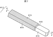
- FIG. 6 is a cross-sectional view taken along line AA of the coil end portion of the conventional stator coil shown in FIG. It is a perspective view of the coil end part of the stator coil which becomes one Example (1st Embodiment) of this invention.
- FIG. 2 is a perspective view in which a rotor of the rotating electrical machine shown in FIG. 1 is sectioned perpendicular to the axial direction. It is a perspective view of the stator which has the winding structure by the lap winding of a coil. It is a perspective view of the coil end part of the conventional stator coil.
- FIG. 6 is a cross-sectional view taken along line AA of the coil
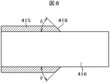
- FIG. 8 is a cross-sectional view taken along line AA of the coil end portion of the stator coil according to the embodiment of the present invention shown in FIG. 7. It is explanatory drawing of the thermal stress of the interface of an insulating film front-end
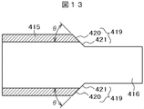
- FIG. 13 is a cross-sectional view taken along line AA of the coil end portion of the stator coil according to another embodiment of the present invention shown in FIG. 12.
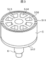
- FIGS. 1 to 3 are cross-sectional views of a squirrel-cage induction motor as a rotating electric machine to which the present invention is applied
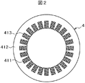
- FIG. 2 is a cross-sectional view of the stator shown in FIG. 1, and FIG. FIG.
- the squirrel-cage induction motor has a bottomed cylindrical housing 1 that is open at one end in the axial direction, and a cover 2 that seals the open end of the housing 1. Is fastened by, for example, six bolts 3.
- a water channel forming member 22 is provided inside the housing 1, and the stator 4 is fixed inside the water channel forming member 22 by shrink fitting or the like.
- a flange at the left end of the water channel forming member 22 is fixed between the housing 1 and the cover 2, and a water channel 24 is formed between the water channel forming member 22 and the housing 1.
- the stator 4 includes a stator core 412 in which a plurality of slots 411 are provided at equal intervals in the circumferential direction, and a three-phase stator coil 413 inserted in each slot 411. It is constituted by.
- Twenty-four slots 411 are formed in the stator core 412 into which the stator coil 413 is inserted, and the stator core 412 is formed by punching a single electromagnetic steel sheet having a thickness of 0.05 to 0.35 mm, for example.
- a plurality of laminated steel sheets formed by laminating several hundreds of formed electromagnetic steel sheets, formed into an annular shape with slots on the inner circumference by etching, and arranged radially at equal intervals in the inner circumference direction Slot 411 is formed.
- the rotor 5 is rotatably arranged on the inner peripheral side of the stator core 412 so as to face the stator core 412 with a minute gap.
- the rotor 5 is fixed to a shaft 6 and rotates integrally with the shaft 6.
- the shaft 6 is rotatably supported by a pair of ball bearings 7a and 7b provided on the housing 1 and the cover 2, respectively.
- the bearing 7 a on the cover 2 side is fixed to the cover 2 by a fixing plate (not shown), and the bearing 7 b is fixed to a recess provided at the bottom of the housing 1.
- a pulley 12 is attached to the left end of the shaft 6 with a nut 11, and a sleeve 9 and a spacer 10 are provided between the pulley 12 of the shaft 6 and the bearing 7a.
- the outer periphery of the sleeve 9 and the inner periphery of the pulley 12 are slightly conical, and the pulley 12 and the shaft 6 are firmly integrated by the tightening force of the nut 11 so that they can rotate integrally. Yes.
- the rotational force of the shaft 6 is output to the outside by the pulley 12, and when used as a generator, from the pulley 12 A rotational force is input to the shaft 6 and is generated by the stator coil.
- a plurality of conductor bars 511 extending in the rotation axis direction are embedded in the rotor core 513 of the rotor 5, which is a cage rotor, at equal intervals over the entire circumference in the circumferential direction.
- the rotor core 513 is made of a magnetic material, and short-circuit rings 512 for short-circuiting the conductor bars 511 are provided at both ends of the rotor core 513 in the axial direction.
- the rotor core 513 is formed by punching or etching an electromagnetic steel sheet having a thickness of 0.05 to 0.35 mm and laminating about several hundreds of the formed electromagnetic steel sheets. Made of laminated steel sheets.
- substantially fan-shaped cavities 514 are provided at equal intervals in the circumferential direction on the inner peripheral side of the rotor core 513 to reduce the weight, and the outer peripheral side of the rotor core 513, that is, the stator side Is embedded with the above-described conductor bar 511, and a magnetic circuit is formed in the rotor yoke 530 inside the conductor bar 511.
- Each conductor bar 511 and the short-circuit ring 512 are made of aluminum or an aluminum alloy, and are integrated with the rotor core 513 by die casting.
- the short-circuit rings 512 arranged at both ends of the rotor core 513 are provided so as to protrude from the rotor core 513 to both ends in the axial direction.
- a detection rotor for detecting the rotation of the rotor 5 is provided on the bottom side of the housing 1, and the rotation sensor 13 detects the teeth of the rotating detection rotor to detect the rotor.
- An electrical signal for detecting the position 5 and the rotational speed of the rotor 5 is output.
- FIG. 4 shows the stator coil 413 that is received in the slot 411 of the stator core 412 and extends in the longitudinal direction from the inside of the stator core to the outside of the stator core.
- One stator coil 413 is inserted into a pair of slots with a predetermined number of slots interposed therebetween.
- Coil end portions (hereinafter referred to as coil ends) 414 are formed on both end surfaces of the stator core 412 by stator coils 413 protruding from the slots to the outside.
- the coil end 414 in the vicinity of the outlet of each slot is provided with a linear portion in which the stator coil 413 extends linearly, and insulating paper is wound between the stator core 412 and the stator coil 413. Yes.
- stator coil 413, the stator core 412 and the insulating paper housed in the stator core 412 are vibrated by the rotational vibration of the rotor 5 which is rotatably provided with a gap.
- it is made of an epoxy-based synthetic resin. Varnish is impregnated in the stator core 412.
- a varnish made of an epoxy-based synthetic resin is coated on the insulating coating surface of the coil to protect the insulating film between the conductor wires of the coil end 414 and the stator coil 413.
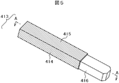
- FIG. 5 is an external view of a coil coupling portion of a conventional coil end 414
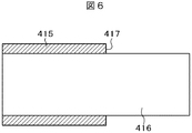
- FIG. 6 is a cross-sectional view taken along line AA of FIG.
- the stator coil 413 is composed of a conductor 416 and a polyamideimide or polyesterimide enamel insulating coating 415 covering the conductor 416 as a whole.
- the insulating film 415 is removed to expose the conductor 416, and the exposed conductor 416 is adjacent to the coil end inserted into the other slot of the stator core 414.
- the conductor 416 is joined by welding.
- the tip of the removal surface 417 of the insulating film 415 is inclined as shown in the cross section of FIG.
- the shape of the right angle was close to 90 ° with respect to the surface of the conductor 416.
- the conductor 416 and the insulating film 415 have different inherent expansion coefficients, so that they behave with each other due to expansion and contraction. If the removal surface 417 of the insulation film 415 is a right-angled shape, the cross-sectional area of the removal surface 417 of the insulation film 415 is almost the same as the cross-sectional area of the normal insulation film 415, and the expansion force and contraction force accompanying expansion and contraction are interrupted. It increases in proportion to the area.
- the removal surface 417 of the insulating film has a shape perpendicular to the conductor 416, the cross-sectional area at the portion of the removal surface 417 is maximized, and a large expansion force and contraction force at this portion are in the axial direction or perpendicular to the conductor. Occurs in one or both directions. For this reason, a large shift occurs between the conductor 416 and the insulating film removal surface 417, resulting in a peeling phenomenon.
- the varnish coated on the insulating coating 415 at the tip of the removal surface 417 of the insulating coating 415 has a thermal contraction force generated when the temperature drops from a high-temperature environment, and at the interface between the insulating coating 415 and the conductor 416. It has been found that a phenomenon that further exfoliates the insulating film 415 from the conductor 416 occurs due to the generated force that promotes the exfoliation.
- the present invention proposes a technique capable of suppressing the phenomenon in which the insulating film 415 is peeled off from the conductor 416 due to the thermal cycle.
- the surface of the insulating film 415 is inclined so that the thickness of the tip of the insulating film 415 of the coil end 414 has a shape that gradually decreases toward the weld joint by welding of the conductor 416. 418 is formed.
- FIG. 7 shows an external view of the coil coupling portion of the coil end 414 in the first embodiment
- FIG. -A shows a cross-sectional view.
- the stator coil 413 is a conducting wire having a rectangular cross section (referred to as a so-called flat wire), and its coil end 414 is a conductor constituting a welded joint from which the insulating film 415 is removed and the insulating film 415 is removed. 416.
- the conductor 416 is formed as a conductor having a rectangular shape including a portion to which the insulating coating 415 is applied, and the insulating coating 415 is uniformly coated on the conductor.
- the inclined surface 418 which has inclination-angle (theta) with respect to the surface of the conductor 416 is formed so that the thickness of only the insulating film 415 may become thin toward the front-end
- the conductor 416 is a flat wire
- the inclined surface 418 having the inclination angle ⁇ is attached so that the thickness of the four tips of the insulating coating 415 in contact with each surface (four surfaces) of the conductor 416 is gradually reduced. Is formed.
- the inclined surface 418 is configured in a straight line here, the inclined surface 418 may actually be a curved line or may have a slight unevenness.
- the thickness of the tip of the insulation film 415 of the coil end 414 has a shape that gradually decreases toward the welded joint by welding of the conductor 416, and the peeling load of the insulation film 415 described later is suppressed to a predetermined value. It should be done.
- the removal surface of the insulating coating 415 is formed with the inclined surface 418 having the inclination angle ⁇ so that the thickness is gradually reduced. Therefore, the expansion force and the contraction force due to the thermal cycle generated in this portion. Since is proportional to the cross-sectional area, it gradually decreases as the cross-sectional area decreases. For this reason, the expansion force and the contraction force become considerably small at the end point of the inclined surface 418. Therefore, peeling between the conductor 416 and the insulating coating 415 inclined surface 418 can be suppressed.
- the peeling of the inclined surface 418 is suppressed by such a configuration, even if the varnish shrinkage force is applied, the inclined surface 418 of the insulating coating 415 is strongly bonded to the first place, thereby suppressing the peeling. Can do.
- the inclination angle ⁇ between the inclined surface 418 at the tip of the insulating coating 415 and the surface of the conductor 416 is preferably set such that the insulating coating 415 and the conductor when the stator coil 413 shifts from high temperature to cooling (or vice versa).
- the peeling force generated at the interface 416 needs to be determined to a value that does not exceed the peeling load of the insulating coating 415.
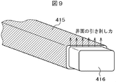
- FIG. 9 shows an explanatory diagram of the thermal stress at the interface between the tip of the insulating coating 415 and the conductor 416
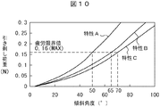
- FIG. 10 shows an explanatory diagram of the peeling load characteristic with respect to the inclination angle of the tip (removal surface) of the insulating coating 415
- the peeling force at the interface between the insulating coating 415 and the conductor 416 tends to become maximum at the tip of the insulating coating 415 when it is heated to 180 ° C. in a thermal cycle and then returned to room temperature 20 ° C. is there.
- the vertical axis in FIG. 10 indicates the value of the peeling load, and the horizontal axis indicates the inclination angle of the inclined surface 418 of the insulating film 415.
- three types of insulating coatings normally used as the insulating coating 415 were prepared.
- FIG. 11 shows an example in the case of actually measuring the peeling load of the insulating coating 415.
- the target coil is a coil in which a polyamideimide layer is applied, a coil in which multiple layers of polyimide and polyamideimide are formed, and a polyimide layer It is a coil that has been constructed.
- variety was set to 1.5 mm and it peeled off, and the load at this time was measured with the force gauge.
- the fatigue limit value for peeling off the insulating coating 415 was approximately 0.16 N at the maximum.
- the inclination angle satisfying the maximum fatigue limit value of 0.16 N is applied to the polyamideimide layer.
- the coil may be set at an inclination angle of 50 ° or less, the coil formed with a plurality of layers of polyimide and polyamideimide may be set at an inclination angle of 65 ° or less, and the coil with a polyimide layer is inclined at 70 ° or less. It can be seen that the angle should be set.
- the insulating film 415 and the conductor 416 are so shaped that the thickness of the tip of the insulating film 415 of the coil end 414 has an inclination that gradually decreases toward the weld joint by welding.
- An inclined surface 419 is formed on the surface.
- FIG. 12 shows an external view of a coil coupling portion of the coil end 414 in the second embodiment
- FIG. -A shows a cross-sectional view.
- the tip surface of only the insulating film 415 is formed to be inclined, whereas in the second embodiment, the tip surface of the insulating film 415 is followed by the insulating film side inclined surface 420 and the following.
- a conductor-side inclined surface 421 is formed inside the conductor main body surface of the conductor 416, and an inclined surface 419 is formed by both.
- the four surfaces of the flat wire are configured so that the surface of the conductor 416 is in contact with the surface of the conductor 416, the tip of the four insulating films 415 and the surface of the conductor 416 are inclined. Yes.
- the inclination angle satisfying the maximum fatigue limit value of 0.16 N is the coil with the polyamideimide layer applied.
- the inclination angle may be set to 50 ° or less, the inclination angle may be set to 65 ° or less for a coil in which a plurality of layers of polyimide and polyamideimide are formed, and the inclination angle is 70 ° or less for a coil having a polyimide layer. It can be seen that it should be set to.
- a continuous inclined surface 419 is formed on the surfaces of the insulating film 415 and the conductor 416, an effect of facilitating the formation method can be expected.
- removing only the insulating film 415 may require a precise technique in the forming process.
- a continuous inclined surface 419 is formed on the surfaces of the insulating film 415 and the conductor 416, so that it can be formed without clearly separating the interface between the insulating film 415 and the conductor 416, and the forming process is compared with the first embodiment. Therefore, it can be expected that no precise technology is required.
- the tip portion of the coil is thinner than that of the first embodiment, it can be expected that the insulating paper pre-installed in the slot can be arranged without damaging when it is arranged on the stator.
- the inclined surface 419 does not have to be strictly linear, and in short, the inclination of the tip of the insulating film 415 of the coil end 414 gradually decreases toward the welded joint by welding of the conductor 416. It is sufficient that the peeling load of the insulating film 415 is suppressed to a predetermined value.
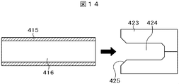
- reference numeral 423 is a press die using a split die.
- the press die 423 has a space 424 in which the stator coil conductor 416 enters, and an inclined angle portion 425 is formed on the inner surface of the tip end side.
- This space 424 forms a conductor 416 exposing the insulating coating 415 of the stator coil, and the inclined corner portion 425 forms an inclined surface 419 shown in FIG.
- the mold 423 is pushed down with a predetermined pressure so that the conductor 416 and the insulating coating 415 have a predetermined shape (here, the shape shown in FIG. 13)). It is something to punch out. In this case, since only two surfaces can be formed in the case of a rectangular wire, the coil is then rotated 90 degrees and punched again with a mold 423 to be completed.
- the thickness of the tip of the insulating film 415 of the coil end 414 is inclined so that it gradually becomes thinner toward the welded joint by welding.
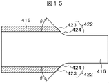
- the inclined surface 422 is formed on the surfaces of the insulating film 415 and the conductor 416.
- the difference from the second embodiment is that the inclined surface formed on the conductor 416 has an arc shape.
- FIG. 15 shows a cross-sectional view of the welded joint portion of the stator coil 414 in the third embodiment.
- the front end surface of the insulating coating 415 is straight as in the second embodiment.
- the surface of the conductor 416 is a smooth arc-shaped conductor side inclined surface 424 as an inclined surface.
- the four sides of the flat wire form an insulating coating 415 in contact with the surface of the conductor 416, a linear inclined surface at the tip of the four insulating coatings 415 on the surface of the conductor 416, and an inclined surface with an arc-shaped surface on the conductor 416. Is configured to do.
- the fatigue limit value after heating to 180 ° C. in the thermal cycle is 0.16 N at the maximum as described in FIG. 10, and therefore the inclination angle satisfying the maximum 0.16 N which is the fatigue limit value is
- the inclination angle may be set to 50 ° or less, and in the multi-layer insulation film of polyimide / polyamideimide, the inclination angle may be set to 65 ° or less.
- the tip portion of the coil is thinner than that in the first embodiment, the insulating paper pre-installed in the slot when being arranged on the stator. The effect that it can arrange
- reference numeral 426 is a press die using a split die.
- This press die 426 has a space 427 into which the stator coil conductor 416 enters, and an inclined angle portion 428 in which an inclined surface and an arc surface are continuously formed is formed on the inner surface of the tip end side.
- the space 427 forms a conductor 416 in which the coil insulating film 415 is exposed, and the inclined corner portion 428 forms the inclined surface 422 shown in FIG. 15.
Landscapes
- Engineering & Computer Science (AREA)
- Power Engineering (AREA)
- Manufacturing & Machinery (AREA)
- Manufacture Of Motors, Generators (AREA)
- Insulation, Fastening Of Motor, Generator Windings (AREA)
Abstract
Description
しかしながら、高熱の熱サイクルの繰り返しによる剥離現象に加えて、ワニスとして使用されているエポキシ系の熱硬化性樹脂では180℃~200℃以上の高温時にワニス自体からガスが発生し、その後の冷えた状態のときにワニスの体積が減少するというワニス自体の熱収縮によって絶縁皮膜の剥離現象を助長するといった副作用が生じているらしいことがわかった。
発明者等の解析の結果によれば、結局のところ特許文献1や特許文献2にある絶縁皮膜の除去法だと絶縁皮膜の除去された先端部分はコイル導体面に対してほぼ直角の状態となっていることがわかった。
図1は本発明が適用される回転電機としてのかご型誘導電動機の断面図であり、図2は図1に示す固定子の断面を示す図であり、図3は回転子を軸方向に垂直な面で断面した斜視図である。
固定子4は図2の断面図に示されるように、複数のスロット411が周方向等間隔に設けられた固定子鉄心412と、各スロット411内に挿入された3相の固定子コイル413とによって構成されている。
そして電動機として使用する場合は、固定子4に対して回転子5が回転駆動されるとプーリー12によってシャフト6の回転力が外部に出力され、また発電機として使用する場合は、プーリー12からの回転力がシャフト6に入力されて固定子コイルによって発電されるものである。
回転子鉄心513は磁性体からなり、回転子鉄心513の軸方向両端には各導体バー511を短絡させる短絡環512がそれぞれ設けられている。
尚、図3の斜視図においては回転子鉄心513と導体バー511との関係を明示するために、回転軸に垂直な面で断面した断面構造を示しており、プーリー12側の短絡環512およびシャフト6は図示していない。
回転子鉄心513の両端に配置された短絡環512は、回転子鉄心513から軸方向両端に突出するように設けられる。
尚、図1に図示していないが、ハウジング1の底部側には回転子5の回転を検出するための検出ロータが設けられ、回転センサ13は回転する検出ロータの歯を検出して回転子5の位置や回転子5の回転速度を検知するための電気信号を出力する。
一つの固定子コイル413は所定数のスロットを間に挟んだ一対のスロットに挿入されている。
各スロットの出口部近傍のコイルエンド414には固定子コイル413が直線状に延在する直線部が設けられており、固定子鉄心412と固定子コイル413との間に絶縁紙が巻き付けられている。
この固定子鉄心412と固定子コイル413の振動を防止するためと、固定子鉄心412に固定子コイル413を挿入した時に出来る傷による電気的な絶縁破壊の防止のためにエポキシ系合成樹脂からなるワニスが固定子鉄心412内に含浸されている。
固定子コイル413は全体として導体416及びこの導体416を被覆しているポリアミドイミドやポリエステルイミドのエナメル質の絶縁被膜415から構成されている。
絶縁皮膜415の除去面417が直角の形状であると絶縁皮膜415の除去面417の断面積は正規の絶縁皮膜415の断面積とほぼ同一となり、膨張と収縮に伴う膨張力と収縮力は断面積に比例して大きくなる。
このため、導体416と絶縁皮膜の除去面417の間に大きなずれを生じることになり、結果として剥離現象が生じることになる。
そこで、本発明では熱サイクルよって絶縁皮膜415が導体416から剥離する現象を抑制することができる技術を提案するものである。
ここで、導体416は絶縁皮膜415が施されている部分を含め形状変化がない断面が長方形状の導体として形成され、絶縁皮膜415もこの導体上に均一に被覆されている。
一つは導体周りにポリアミドイミド層を施工したコイル(特性A)、一つは導体周りにポリイミドとポリアミドイミドの複数層を形成したコイル(特性B)、一つは導体周りにポリイミド層を施工したコイル(特性C)である。
そして、この絶縁被膜415と導体416の界面の引き剥がし力が絶縁被膜415を引き剥がす疲労限界値を超えると剥離が生じてしまうことがわかる。
そして、熱サイクルで180℃に加熱した後に常温20℃に戻した状態で、引き剥がし幅を1.5mmに設定して引き剥がし、このときの荷重をフォースゲージにて測定した。この結果、絶縁被膜415を引き剥がす疲労限界値はおおよそで最大で約0.16Nであった。
この実施例においても、平角線の4面は導体416の面に接する絶縁被膜415と導体416の表面に4箇所の絶縁皮膜415の先端と導体416に表面が傾斜を形成するように構成されている。
この他、この実施形態によれば第1の実施形態に比べて、絶縁皮膜415と導体416の表面に連続した傾斜面419を形成するとその形成方法が容易になるといった効果を期待できる。
そして、金型423の下に絶縁被膜が施された固定子コイルを設置すると、金型423を所定の圧力で押し下げて導体416と絶縁被膜415を所定形状(ここでは図13に示す形状))に打ち抜くものである。この場合は平角線の場合は2面しか形成できないので、次にこのコイルを90度回転させて再度金型423で打ち抜いて完成されるものである。
ここで、第2の実施形態と異なる点は導体416に形成した傾斜面が円弧状を成していることである。
418…傾斜面、419…傾斜面、420…絶縁皮膜側傾斜面、421…直線状の導体側傾斜面、422…傾斜面、423…絶縁皮膜側傾斜面、424…円弧状の傾斜面
423…金型、424…空間、425…傾斜角部。
Claims (12)
- 回転子収納空間を備えた円環状の固定子鉄心と、前記固定子鉄心の内周に等間隔に設けられた複数のスロットと、前記スロットに挿入され隣接するコイルと溶接結合部によって結合されるコイルエンドをそれぞれ有し前記コイルエンド以外に絶縁皮膜が施された複数のコイルと、前記回転子収納空間に収納された回転子とを少なくとも備えた回転電機において、
前記コイルエンドに至る前記絶縁皮膜の先端に、その厚みが前記コイルエンドの前記溶接結合部に向かって徐々に薄くなる傾斜をもつ傾斜面を形成したことを特徴とする回転電機。 - 請求項1に記載の回転電機において、前記傾斜面は前記絶縁皮膜の先端にだけ形成されていることを特徴とする回転電機。
- 請求項1に記載の回転電機において、前記傾斜面は前記絶縁被膜の先端と前記コイルエンドの導体の表面から内部側に向かって形成されていること特徴とする回転電機。
- 請求項3に記載の回転電機において、前記コイルエンドの導体の表面から内部側に向かって形成されている傾斜面は直線状に形成されていることを特徴とする回転電機。
- 請求項3に記載の回転電機において、前記コイルエンドの導体の表面から内部側に向かって形成されている傾斜面は円弧状に形成されていることを特徴とする回転電機。
- 請求項1乃至請求項5に記載の回転電機において、前記絶縁被膜がポリアミドイミド及びポリイミドを含む複数層から形成されているときの前記絶縁被膜の先端に形成した傾斜面の傾斜角度は65°以下の傾斜角度であることを特徴とする回転電機。
- 請求項1乃至請求項5に記載の回転電機において、前記絶縁被膜がポリアミドイミドであるときの前記絶縁被膜の先端に形成した傾斜面の傾斜角度は50°以下の傾斜角度であることを特徴とする回転電機。
- 請求項1乃至請求項5に記載の回転電機において、前記絶縁被膜がポリイミドであるときの前記絶縁被膜の先端に形成した傾斜面の傾斜角度は70°以下の傾斜角度であることを特徴とする回転電機。
- 請求項1に記載の回転電機おいて、前記コイルは角線であって前記絶縁被膜は前記角線の4面に施され、前記絶縁皮膜の先端にその厚みが前記コイルエンドの前記溶接結合部に向かって徐々に薄くなる傾斜をもつ傾斜面を形成したことを特徴とする回転電機。
- 回転子収納空間を備えた円環状の固定子鉄心と、前記固定子鉄心の内周に等間隔に設けられた複数のスロットと、前記スロットに挿入され隣接するコイルと溶接結合部によって結合されるコイルエンドをそれぞれ有し前記コイルエンド以外に絶縁皮膜が施された複数のコイルと、前記回転子収納空間に収納された回転子とを少なくとも備えた回転電機において、
前記コイルエンドに施された前記絶縁皮膜が前記コイルエンドの前記溶接結合部に向かって徐々に薄くなるような傾斜をもつ形状に打ち抜く金型の打ち抜き工程によって前記絶縁被膜の先端に傾斜面を形成することを特徴とする回転電機の固定子コイルの製造方法。 - 回転子収納空間を備えた円環状の固定子鉄心と、前記固定子鉄心の内周に等間隔に設けられた複数のスロットと、前記スロットに挿入され隣接するコイルと溶接結合部によって結合されるコイルエンドをそれぞれ有し前記コイルエンド以外に絶縁皮膜が施された複数のコイルと、前記回転子収納空間に収納された回転子とを少なくとも備えた回転電機において、
前記コイルエンドに施された前記絶縁皮膜及び前記コイルの導体の表面から内側を前記コイルエンドの前記溶接結合部に向かって徐々に薄くなるような傾斜をもつ形状に打ち抜く金型の打ち抜き工程によって前記絶縁被膜の先端及び前記導体の内側に傾斜面を形成することを特徴とする回転電機の固定子コイルの製造方法。 - 請求項11に記載の回転電機の固定子コイルの製造方法において、前記傾斜面は前記絶縁被膜及び前記導体に亘って直線状に形成する金型の打ち抜き工程によって形成されるか、或いは前記絶縁被膜は直線状に形成され、かつ前記導体は円弧状に形成する金型の打ち抜き工程によって形成されることを特徴とする回転電機の固定子コイルの製造方法。
Priority Applications (3)
| Application Number | Priority Date | Filing Date | Title |
|---|---|---|---|
| CN201280034510.XA CN103650299A (zh) | 2011-07-14 | 2012-06-11 | 旋转电机以及旋转电机的定子线圈的制造方法 |
| US14/131,009 US20140183985A1 (en) | 2011-07-14 | 2012-06-11 | Rotating Electric Machine and Method for Manufacturing Stator Coil of Rotating Electric Machine |
| DE112012002959.3T DE112012002959T5 (de) | 2011-07-14 | 2012-06-11 | Rotierende Elektromaschine und Verfahren zur Herstellung einer Statorspule einer rotierenden Elektromaschine |
Applications Claiming Priority (2)
| Application Number | Priority Date | Filing Date | Title |
|---|---|---|---|
| JP2011-155855 | 2011-07-14 | ||
| JP2011155855A JP2013021896A (ja) | 2011-07-14 | 2011-07-14 | 回転電機及び回転電機の固定子コイルの製造方法 |
Publications (1)
| Publication Number | Publication Date |
|---|---|
| WO2013008568A1 true WO2013008568A1 (ja) | 2013-01-17 |
Family
ID=47505866
Family Applications (1)
| Application Number | Title | Priority Date | Filing Date |
|---|---|---|---|
| PCT/JP2012/064870 Ceased WO2013008568A1 (ja) | 2011-07-14 | 2012-06-11 | 回転電機及び回転電機の固定子コイルの製造方法 |
Country Status (5)
| Country | Link |
|---|---|
| US (1) | US20140183985A1 (ja) |
| JP (1) | JP2013021896A (ja) |
| CN (1) | CN103650299A (ja) |
| DE (1) | DE112012002959T5 (ja) |
| WO (1) | WO2013008568A1 (ja) |
Cited By (1)
| Publication number | Priority date | Publication date | Assignee | Title |
|---|---|---|---|---|
| EP3032710A4 (en) * | 2013-08-08 | 2017-05-10 | Hitachi Automotive Systems, Ltd. | Rotating electrical machine |
Families Citing this family (12)
| Publication number | Priority date | Publication date | Assignee | Title |
|---|---|---|---|---|
| JP5842856B2 (ja) * | 2013-04-08 | 2016-01-13 | 株式会社デンソー | 回転電機の固定子 |
| JP6093269B2 (ja) * | 2013-08-19 | 2017-03-08 | トヨタ自動車株式会社 | セグメントコイル及びステータ |
| JP5681248B1 (ja) * | 2013-08-26 | 2015-03-04 | 本田技研工業株式会社 | コイルセグメント製造装置及びコイルセグメント製造方法 |
| JP2016081732A (ja) * | 2014-10-17 | 2016-05-16 | 矢崎総業株式会社 | 電線及び電線の製造方法 |
| KR102566474B1 (ko) * | 2016-04-22 | 2023-08-11 | 엘지이노텍 주식회사 | 모터용 코일 및 모터용 코일 가공 장치 |
| JP6423398B2 (ja) * | 2016-09-20 | 2018-11-14 | 本田技研工業株式会社 | 剥離装置及び剥離方法 |
| CN109586448A (zh) * | 2017-09-29 | 2019-04-05 | 比亚迪股份有限公司 | 导体段及具有其的定子组件、电机 |
| JP6939503B2 (ja) * | 2017-12-15 | 2021-09-22 | トヨタ自動車株式会社 | 平角導体の切断方法 |
| JP7302443B2 (ja) * | 2019-11-11 | 2023-07-04 | 株式会社デンソー | 回転電機 |
| CN114762228A (zh) * | 2020-01-31 | 2022-07-15 | 株式会社爱信 | 导线的绝缘覆膜的剥离方法 |
| DE102020133274A1 (de) | 2020-12-14 | 2022-06-15 | Bayerische Motoren Werke Aktiengesellschaft | Anordnung eines Kontaktelements an freien Spulenleiterenden einer elektrischen Maschine, elektrische Maschine für ein Kraftfahrzeug, Verfahren zum Bereitstellen eines Kontaktelements für eine elektrische Maschine sowie Kraftfahrzeug |
| DE102022118373A1 (de) * | 2021-07-26 | 2023-01-26 | Denso Corporation | Stator und Verfahren zur Herstellung desselben |
Citations (9)
| Publication number | Priority date | Publication date | Assignee | Title |
|---|---|---|---|---|
| JPS62293700A (ja) * | 1986-06-12 | 1987-12-21 | 松下電器産業株式会社 | 電子部品のリ−ド線切断装置 |
| JPH0238144U (ja) * | 1988-09-08 | 1990-03-14 | ||
| JP2000295821A (ja) * | 1999-04-02 | 2000-10-20 | Denso Corp | 対導線配列及び対導線の端部接合方法及びそれを用いた回転電機の巻線製造方法 |
| JP2003047213A (ja) * | 2001-07-30 | 2003-02-14 | Toyota Motor Corp | 絶縁電線の接合方法 |
| JP2005304223A (ja) * | 2004-04-14 | 2005-10-27 | Hitachi Cable Ltd | オルタネータ用ステータコイル |
| JP2006333562A (ja) * | 2005-05-24 | 2006-12-07 | Hitachi Ltd | 接合電線と接合電線の加工方法,回転電機の固定子と回転電機の固定子の製造方法及び接合電線製造装置 |
| JP2008199751A (ja) * | 2007-02-09 | 2008-08-28 | Denso Corp | 回転電機の固定子巻線およびその製造方法 |
| JP2009081980A (ja) * | 2007-09-27 | 2009-04-16 | Hitachi Ltd | 回転電機及びその固定子 |
| JP2010124636A (ja) * | 2008-11-20 | 2010-06-03 | Sumitomo Electric Ind Ltd | コイルユニットおよびステータ |
Family Cites Families (5)
| Publication number | Priority date | Publication date | Assignee | Title |
|---|---|---|---|---|
| JP4462392B2 (ja) * | 2000-02-23 | 2010-05-12 | 三菱電機株式会社 | 交流発電機の固定子の製造方法 |
| JP3964116B2 (ja) * | 2000-09-12 | 2007-08-22 | 三菱電機株式会社 | 回転電機の固定子 |
| JP2006317412A (ja) * | 2005-05-16 | 2006-11-24 | Totoku Electric Co Ltd | 絶縁被膜付きプローブ針及びその製造方法 |
| JP4628228B2 (ja) * | 2005-09-13 | 2011-02-09 | 日特エンジニアリング株式会社 | 線材の皮膜剥離装置及び剥離方法 |
| JP2008236924A (ja) * | 2007-03-22 | 2008-10-02 | Hitachi Ltd | 回転電機及び電気自動車 |
-
2011
- 2011-07-14 JP JP2011155855A patent/JP2013021896A/ja active Pending
-
2012
- 2012-06-11 DE DE112012002959.3T patent/DE112012002959T5/de not_active Withdrawn
- 2012-06-11 CN CN201280034510.XA patent/CN103650299A/zh active Pending
- 2012-06-11 US US14/131,009 patent/US20140183985A1/en not_active Abandoned
- 2012-06-11 WO PCT/JP2012/064870 patent/WO2013008568A1/ja not_active Ceased
Patent Citations (9)
| Publication number | Priority date | Publication date | Assignee | Title |
|---|---|---|---|---|
| JPS62293700A (ja) * | 1986-06-12 | 1987-12-21 | 松下電器産業株式会社 | 電子部品のリ−ド線切断装置 |
| JPH0238144U (ja) * | 1988-09-08 | 1990-03-14 | ||
| JP2000295821A (ja) * | 1999-04-02 | 2000-10-20 | Denso Corp | 対導線配列及び対導線の端部接合方法及びそれを用いた回転電機の巻線製造方法 |
| JP2003047213A (ja) * | 2001-07-30 | 2003-02-14 | Toyota Motor Corp | 絶縁電線の接合方法 |
| JP2005304223A (ja) * | 2004-04-14 | 2005-10-27 | Hitachi Cable Ltd | オルタネータ用ステータコイル |
| JP2006333562A (ja) * | 2005-05-24 | 2006-12-07 | Hitachi Ltd | 接合電線と接合電線の加工方法,回転電機の固定子と回転電機の固定子の製造方法及び接合電線製造装置 |
| JP2008199751A (ja) * | 2007-02-09 | 2008-08-28 | Denso Corp | 回転電機の固定子巻線およびその製造方法 |
| JP2009081980A (ja) * | 2007-09-27 | 2009-04-16 | Hitachi Ltd | 回転電機及びその固定子 |
| JP2010124636A (ja) * | 2008-11-20 | 2010-06-03 | Sumitomo Electric Ind Ltd | コイルユニットおよびステータ |
Cited By (2)
| Publication number | Priority date | Publication date | Assignee | Title |
|---|---|---|---|---|
| EP3032710A4 (en) * | 2013-08-08 | 2017-05-10 | Hitachi Automotive Systems, Ltd. | Rotating electrical machine |
| US10230281B2 (en) | 2013-08-08 | 2019-03-12 | Hitachi Automotive Systems, Ltd. | Rotating electrical machine |
Also Published As
| Publication number | Publication date |
|---|---|
| CN103650299A (zh) | 2014-03-19 |
| DE112012002959T5 (de) | 2014-04-17 |
| US20140183985A1 (en) | 2014-07-03 |
| JP2013021896A (ja) | 2013-01-31 |
Similar Documents
| Publication | Publication Date | Title |
|---|---|---|
| JP2013021896A (ja) | 回転電機及び回転電機の固定子コイルの製造方法 | |
| JP5066062B2 (ja) | 回転電機および回転電機の製造方法 | |
| CN113196618B (zh) | 层叠铁芯及旋转电机 | |
| JP6122148B2 (ja) | 回転電機 | |
| US7788790B2 (en) | Method for forming a stator core | |
| JP5624942B2 (ja) | 回転電機およびその製造方法 | |
| CN103201931B (zh) | 旋转电机 | |
| JP6156250B2 (ja) | 回転電機の固定子及びその固定子を備えた回転電機 | |
| US8772988B2 (en) | Stator structure for electric machine | |
| US10298084B2 (en) | Rotating electric machine for vehicle | |
| JP2006129688A (ja) | 磁石式発電機 | |
| US20160336828A1 (en) | Rotating electric machine stator | |
| WO2014102950A1 (ja) | 回転電機 | |
| CN111245164A (zh) | 旋转电机及其制造方法 | |
| JP5609211B2 (ja) | 回転電機の固定子及び回転電機の固定子の製造方法 | |
| CN107636937B (zh) | 旋转电机 | |
| JP5819037B2 (ja) | 回転電機の固定子及び回転電機 | |
| JP5359463B2 (ja) | ステータおよび回転電機 | |
| JP2013165579A (ja) | 平角導体の絶縁皮膜除去方法 | |
| JP5573640B2 (ja) | ディスク型回転機コア | |
| WO2008012880A1 (fr) | Machine dynamo-électrique | |
| US12614959B2 (en) | Armature winding and method for manufacturing same | |
| JP2014100040A (ja) | 回転電機の固定子 | |
| JP6515322B2 (ja) | 回転電機の固定子 | |
| JP7595407B2 (ja) | 積層コア及び回転電機 |
Legal Events
| Date | Code | Title | Description |
|---|---|---|---|
| 121 | Ep: the epo has been informed by wipo that ep was designated in this application |
Ref document number: 12811261 Country of ref document: EP Kind code of ref document: A1 |
|
| WWE | Wipo information: entry into national phase |
Ref document number: 14131009 Country of ref document: US |
|
| WWE | Wipo information: entry into national phase |
Ref document number: 1120120029593 Country of ref document: DE Ref document number: 112012002959 Country of ref document: DE |
|
| 122 | Ep: pct application non-entry in european phase |
Ref document number: 12811261 Country of ref document: EP Kind code of ref document: A1 |