WO2013002005A1 - 画像形成装置 - Google Patents
画像形成装置 Download PDFInfo
- Publication number
- WO2013002005A1 WO2013002005A1 PCT/JP2012/064737 JP2012064737W WO2013002005A1 WO 2013002005 A1 WO2013002005 A1 WO 2013002005A1 JP 2012064737 W JP2012064737 W JP 2012064737W WO 2013002005 A1 WO2013002005 A1 WO 2013002005A1
- Authority
- WO
- WIPO (PCT)
- Prior art keywords
- photosensitive drums
- image forming
- photosensitive
- transfer belt
- toner
- Prior art date
- Legal status (The legal status is an assumption and is not a legal conclusion. Google has not performed a legal analysis and makes no representation as to the accuracy of the status listed.)
- Ceased
Links
Images




Classifications
-
- G—PHYSICS
- G03—PHOTOGRAPHY; CINEMATOGRAPHY; ANALOGOUS TECHNIQUES USING WAVES OTHER THAN OPTICAL WAVES; ELECTROGRAPHY; HOLOGRAPHY
- G03G—ELECTROGRAPHY; ELECTROPHOTOGRAPHY; MAGNETOGRAPHY
- G03G21/00—Arrangements not provided for by groups G03G13/00 - G03G19/00, e.g. cleaning, elimination of residual charge
- G03G21/0005—Arrangements not provided for by groups G03G13/00 - G03G19/00, e.g. cleaning, elimination of residual charge for removing solid developer or debris from the electrographic recording medium
- G03G21/0011—Arrangements not provided for by groups G03G13/00 - G03G19/00, e.g. cleaning, elimination of residual charge for removing solid developer or debris from the electrographic recording medium using a blade; Details of cleaning blades, e.g. blade shape, layer forming
-
- G—PHYSICS
- G03—PHOTOGRAPHY; CINEMATOGRAPHY; ANALOGOUS TECHNIQUES USING WAVES OTHER THAN OPTICAL WAVES; ELECTROGRAPHY; HOLOGRAPHY
- G03G—ELECTROGRAPHY; ELECTROPHOTOGRAPHY; MAGNETOGRAPHY
- G03G15/00—Apparatus for electrographic processes using a charge pattern
- G03G15/01—Apparatus for electrographic processes using a charge pattern for producing multicoloured copies
- G03G15/0142—Structure of complete machines
- G03G15/0178—Structure of complete machines using more than one reusable electrographic recording member, e.g. one for every monocolour image
- G03G15/0189—Structure of complete machines using more than one reusable electrographic recording member, e.g. one for every monocolour image primary transfer to an intermediate transfer belt
-
- G—PHYSICS
- G03—PHOTOGRAPHY; CINEMATOGRAPHY; ANALOGOUS TECHNIQUES USING WAVES OTHER THAN OPTICAL WAVES; ELECTROGRAPHY; HOLOGRAPHY
- G03G—ELECTROGRAPHY; ELECTROPHOTOGRAPHY; MAGNETOGRAPHY
- G03G2215/00—Apparatus for electrophotographic processes
- G03G2215/01—Apparatus for electrophotographic processes for producing multicoloured copies
- G03G2215/0103—Plural electrographic recording members
- G03G2215/0119—Linear arrangement adjacent plural transfer points
- G03G2215/0122—Linear arrangement adjacent plural transfer points primary transfer to an intermediate transfer belt
- G03G2215/0125—Linear arrangement adjacent plural transfer points primary transfer to an intermediate transfer belt the linear arrangement being horizontal or slanted
- G03G2215/0132—Linear arrangement adjacent plural transfer points primary transfer to an intermediate transfer belt the linear arrangement being horizontal or slanted vertical medium transport path at the secondary transfer
-
- G—PHYSICS
- G03—PHOTOGRAPHY; CINEMATOGRAPHY; ANALOGOUS TECHNIQUES USING WAVES OTHER THAN OPTICAL WAVES; ELECTROGRAPHY; HOLOGRAPHY
- G03G—ELECTROGRAPHY; ELECTROPHOTOGRAPHY; MAGNETOGRAPHY
- G03G2215/00—Apparatus for electrophotographic processes
- G03G2215/01—Apparatus for electrophotographic processes for producing multicoloured copies
- G03G2215/019—Structural features of the multicolour image forming apparatus
- G03G2215/0193—Structural features of the multicolour image forming apparatus transfer member separable from recording member
Definitions
- the present invention relates to an image forming apparatus that releases the pressure of toner accumulated between a photosensitive drum and a cleaning blade.
- the toner on the photosensitive drum is removed by sliding the tip edge of the cleaning blade against the photosensitive drum. Yes. For this reason, the toner is accumulated between the photosensitive drum and the cleaning blade by continuous use. If left untreated, the toner slips between the photosensitive drum and the cleaning blade, which may cause toner scattering or an abnormal image such as black or white streaks appearing on the formed image.
- a drive unit that can rotate the photosensitive drum in both forward and reverse directions.
- the photosensitive drum rotates in the direction opposite to the rotational direction during image formation and adheres to the tip ridge of the cleaning blade.
- An image forming apparatus that peels off and removes the toner that has been removed from the edge portion of the tip is disclosed (for example, see Patent Document 1).
- an object of the present invention is to provide an image forming apparatus capable of releasing the pressure of toner accumulated between a photosensitive drum and a cleaning blade without affecting the life of the photosensitive drum. It is to provide.
- the image forming apparatus is a tandem type image forming apparatus that performs monochrome image forming processing and color image forming processing.
- the image forming apparatus according to the present invention includes a plurality of first photosensitive drums, a second photosensitive drum, an intermediate transfer belt, a plurality of cleaning blades, a switching mechanism, and a reverse rotation mechanism.
- the plurality of first photosensitive drums carry a single color toner image on the surface.
- the second photosensitive drum carries a black toner image on the surface.
- a toner image is transferred from at least one of the plurality of first photosensitive drums and the second photosensitive drum in a contact state with the plurality of first photosensitive drums and the second photosensitive drums.
- the plurality of cleaning blades are in sliding contact with each of the plurality of first photosensitive drums and the second photosensitive drums in order to remove the toner remaining on the plurality of first photosensitive drums and the second photosensitive drums after the transfer.
- the switching mechanism switches the contact state between the plurality of first and second photosensitive drums and the intermediate transfer belt to the separated state after the color image forming process is completed.
- the reverse rotation mechanism reversely rotates the plurality of first photosensitive drums after switching the plurality of first photosensitive drums, the second photosensitive drum, and the intermediate transfer belt to the separated state by the switching mechanism.
- the plurality of first photosensitive drums are reversely rotated while the plurality of first photosensitive drums and the second photosensitive drums are not in contact with the intermediate transfer belt, the plurality of first photosensitive drums are reversely rotated. Since the drum and the intermediate transfer belt are not in sliding contact with each other, the influence on the life of the plurality of first photosensitive drums can be reduced and the burden on the rotational drive system of the plurality of first photosensitive drums can be reduced. can do.
- the image forming apparatus can release the pressure of the toner accumulated between the photosensitive drum and the cleaning blade without affecting the life of the photosensitive drum.
- FIG. 1 is a front view illustrating a configuration of an image forming apparatus according to an embodiment of the present invention.
- FIG. 4 is a diagram illustrating a contact state between a first photosensitive drum and a second photosensitive drum and an intermediate transfer belt.
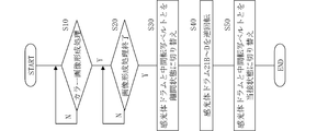
- 1 is a block diagram illustrating a main part of an image forming apparatus according to an embodiment of the present invention. 4 is a flowchart illustrating control contents of the image forming apparatus according to the embodiment of the present invention.
- FIG. 3 is a diagram illustrating a state where a first photosensitive drum, a second photosensitive drum, and an intermediate transfer belt are separated from each other.
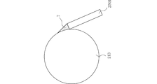
- FIG. 6 is a diagram illustrating a state of toner accumulated between a first photosensitive drum and a cleaning blade.
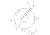
- FIG. 5 is a diagram illustrating a state in which toner accumulated between the first photosensitive drum and the cleaning blade is dispersed by reverse rotation of the first photosensitive drum. It is a figure which shows the modification of a reverse rotation mechanism.
- FIG. 1 is a front view showing a configuration of an image forming apparatus 10 according to an embodiment of the present invention.
- the image forming apparatus 10 includes a plurality of image forming units 20A, 20B, 20C, and 20D, a primary transfer unit 30, a secondary transfer unit 40, a fixing device 51, a paper transport path 52, a paper feed cassette 53, a manual feed tray 54, and paper discharge.
- a tray 55 and a control unit 60 are provided.
- the control unit 60 comprehensively controls each unit of the image forming apparatus 10. Note that the image forming units 20A to 20D are appropriately referred to as an image forming unit 20.
- the image forming apparatus 10 performs an electrophotographic image forming process using image data corresponding to four hues of black, cyan, magenta, and yellow.
- the image forming units 20B to 20D are configured substantially in the same manner as the image forming unit 20A.
- the black image forming unit 20A includes a photosensitive drum 21A, a charging device 22A, an exposure device 23A, a developing device 24A, and a cleaning unit 25A, and forms a black toner image through an electrophotographic image forming process.
- the photosensitive drums 21B, 21C, and 21D respectively provided in the photosensitive drum 21A and the image forming units 20B to 20D rotate by receiving driving force from a driving motor (not shown).
- the charging device 22A is disposed so as to face the circumferential surface of the photosensitive drum 21A, and charges the circumferential surface of the photosensitive drum 21A to a predetermined potential.
- the exposure device 23A irradiates the peripheral surface of the photosensitive drum 21A with a laser beam modulated by the image data for black.
- the developing device 24A contains black toner.
- the primary transfer unit 30 includes a primary transfer belt 31, a primary transfer driving roller 32, a primary transfer driven roller 33, primary transfer rollers 34A to 34D, and a primary transfer belt cleaning unit 35.
- the primary transfer belt 31 is stretched between a primary transfer driving roller 32 and a primary transfer driven roller 33, and moves around in a predetermined direction.
- the primary transfer rollers 34A to 34D are arranged so as to face the photosensitive drums 21A to 21D with the primary transfer belt 31 interposed therebetween.
- a region where the outer peripheral surface of the primary transfer belt 31 and the photosensitive drums 21A to 21D face each other is a primary transfer region.
- the cleaning unit 25A collects the toner remaining on the peripheral surface of the photosensitive drum 21A after development and primary transfer.
- the secondary transfer unit 40 is configured to be able to contact and separate from the primary transfer driving roller 32 with the primary transfer belt 31 interposed therebetween.
- the area where the primary transfer belt 31 and the secondary transfer unit 40 are in pressure contact is the secondary transfer area.
- the paper feed cassette 53 and the manual feed tray 54 contain paper.
- the paper transport path 52 is configured to guide the paper fed from the paper feed cassette 53 or the manual feed tray 54 to the paper discharge tray 55 via the secondary transfer area and the fixing device 51.
- a registration roller 56 is disposed in the vicinity of the upstream side of the secondary transfer area in the paper transport direction.
- the paper fed from the paper feed cassette 53 or the manual feed tray 54 to the paper conveyance path 52 is corrected in its direction by being abutted against the resist roller 56 in a stopped state, and starts to rotate at a predetermined timing. Is supplied to the secondary transfer region.
- the toner image carried on the primary transfer belt 31 is secondarily transferred to the paper.
- the toner remaining on the primary transfer belt 31 without being transferred to the paper is collected by the primary transfer belt cleaning unit 35. This prevents color mixing in the next step.
- the fixing device 51 has a heating roller 511 and a pressure roller 512.
- the heating roller 511 and the pressure roller 512 are in pressure contact with each other.
- the fixing device 51 heats and presses the sheet by conveying the sheet while sandwiching the sheet at the nip portion between the heating roller 511 and the pressure roller 512, thereby firmly fixing the toner image on the sheet.
- the sheet on which the toner image is fixed is discharged onto the discharge tray 55 by the discharge roller pair 57.
- FIG. 2 is a front view showing a main part of the image forming apparatus 10 according to the embodiment of the present invention.
- FIG. 3 is a block diagram showing a main part of the image forming apparatus 10 according to the embodiment of the present invention.
- the image forming apparatus 10 includes photosensitive drums 21A to 21D, an intermediate transfer belt 31, cleaning blades 250A to 250D, a cam mechanism 36, a drive motor 26, a CPU 60, a ROM 61, and a RAM 62.
- the photoconductor drums 21B to 21D correspond to the first photoconductor drum of the present invention.
- the photoreceptor drum 21A corresponds to the second photoreceptor drum of the present invention.
- the cam mechanism 36 corresponds to the switching mechanism of the present invention.
- the drive motor 26 corresponds to the reverse rotation mechanism of the present invention.
- the photosensitive drums 21B to 21D carry a single color toner image on the surface.
- the photosensitive drum 21A carries a black toner image on the surface.
- the intermediate transfer belt 31 has a toner image transferred from at least one of the photosensitive drums 21A to 21D in a contact state with the photosensitive drums 21A to 21D.
- the cleaning blades 250A to 250D are provided in the cleaning units 25A to 25D, respectively, and come into sliding contact with the photosensitive drums 21A to 21D in order to remove the toner remaining on the photosensitive drums 21A to 21D after the transfer.
- the cam mechanism 36 switches the contact state between the photosensitive drums 21A to 21D and the intermediate transfer belt 31 to the separated state after the color image forming process is completed.
- the drive motor 26 reversely rotates the photosensitive drums 21B to 21D after switching the photosensitive drums 21A to 21D and the intermediate transfer belt 31 to the separated state by the cam mechanism 36.
- the CPU 60 reads out and executes a control program from the ROM 61, and controls each part collectively.
- the ROM 61 stores a control program read by the CPU 60.
- the RAM 62 is used as a working area for the CPU 60.
- FIG. 4 is a flowchart showing the control contents of the image forming apparatus 10 according to the embodiment of the present invention.
- the CPU 60 waits until a color image formation command is issued (N in S10). If the CPU 60 determines that a color image formation command has been issued (Y in S10), the CPU 60 waits until the color image formation process is completed (N in S20). When the CPU 60 determines that the color image forming process has been completed (Y in S20), the CPU 60 controls the contact state between the photosensitive drums 21A to 21D and the intermediate transfer belt 31 to the separated state via the cam mechanism 36 ( S30). The separated state is shown in FIG. Thereafter, the CPU 60 performs control to reversely rotate the photosensitive drums 21B to 21D via the drive motor 26 (S40).
- toner T is accumulated between the photosensitive drum 21B and the cleaning blade 250B.
- the reverse rotation control is performed from this state, as shown in FIG. 7, the toner T is dispersed, and the pressure of the toner T between the photosensitive drum 21B and the cleaning blade 250B is released.
- the photosensitive drum 21B has been described as an example, but the same applies to the photosensitive drums 21C and 21D.
- the CPU 60 switches the separated state between the photosensitive drums 21A to 21D and the intermediate transfer belt 31 to the contact state (S50), and ends the control of the present embodiment.
- the pressure of the toner T accumulated between the photosensitive drums 21B to 21D and the cleaning blades 250B to 250D can be released by performing the reverse rotation of the photosensitive drums 21B to 21D. It is possible to prevent the occurrence of image defects due to slipping through.
- the photosensitive drums 21B to 21D are reversely rotated without contacting the photosensitive drums 21A to 21D and the intermediate transfer belt 31, the photosensitive drums 21B to 21D and the intermediate transfer belt 31 are rotated during the reverse rotation. Therefore, the influence on the life of the photosensitive drums 21B to 21D can be reduced and the burden on the rotational drive system (for example, the drive motor 26) of the photosensitive drums 21B to 21D can be reduced. Can do.
- the cam mechanism 36 does not switch the contact state between the photosensitive drums 21A to 21D and the intermediate transfer belt 31 to the separated state after the monochrome image forming process is finished, and the drive motor 26 finishes the monochrome image forming process. After that, it is preferable not to reversely rotate the photosensitive drums 21B to 21D.
- the toner T does not collect between the photosensitive drums 21B to 21D and the cleaning blades 250B to 250D, so that the photosensitive drums 21A to 21D and the intermediate transfer belt 31 are in contact with each other. It is not necessary to reverse the rotation of the photosensitive drums 21B to 21D by switching the state to the separated state. Accordingly, it is possible to reduce the influence on the life of the photoconductive drums 21B to 21D and reduce the burden on the rotation drive system (for example, the drive motor 26) of the photoconductive drums 21B to 21D.
- the rotation drive system for example, the drive motor 26
- the drive motor 26 does not reversely rotate the photosensitive drum 21A.
- the drive motor 26 only needs to rotate the photosensitive drums 21B to 21D in reverse by a minute angle.
- the drive motor 26 only needs to reversely rotate the photosensitive drums 21B to 21D by an angle that releases the pressure of the toner T accumulated between the photosensitive drums 21B to 21D and the cleaning blades 250B to 250D. .
- the drive motor 26 only needs to reversely rotate the photosensitive drums 21B to 21D by a circumference of several millimeters.
- the pressure of the toner T accumulated between the photosensitive drums 21B to 21D and the cleaning blades 250B to 250D can be released. Occurrence of image defects due to slipping can be prevented. Accordingly, it is possible to reduce the influence on the life of the photoconductive drums 21B to 21D and reduce the burden on the rotation drive system (for example, the drive motor 26) of the photoconductive drums 21B to 21D.
- the drive motor 26 is described as an example of the reverse rotation mechanism, but the present invention is not limited to this.
- a structure as shown in FIG. 8 may be adopted as the reverse rotation mechanism.
- the support shaft 27A is provided in the gear 27 of the rotational drive system of the photosensitive drum 21B
- the support shaft 27B is provided in the vicinity of the photosensitive drum 21B
- the tension spring 28 is supported by the support shafts 27A and 27B.
- the photosensitive drum 21B is urged via The support shafts 27A and 27B and the tension spring 28 in this configuration correspond to the reverse rotation mechanism of the present invention.
- the photosensitive drums 21C and 21D have the same configuration.
Landscapes
- Physics & Mathematics (AREA)
- General Physics & Mathematics (AREA)
- Cleaning In Electrography (AREA)
- Electrophotography Configuration And Component (AREA)
Abstract
感光体ドラムの寿命に影響を与えることなく、感光体ドラムとクリーニングブレードとの間にたまったトナーの圧力を解除することができる画像形成装置を提供する。 画像形成装置(10)は、感光体ドラム(21A~21D)、中間転写ベルト(31)、クリーニングブレード(250A~250D)、カム機構(36)および駆動モータ(26)を備える。感光体ドラム(21B~21D)は、トナー像を担持する。中間転写ベルトは、感光体ドラム(21A~21D)からトナー像が転写される。クリーニングブレード(250A~250D)は、転写後の感光体ドラム(21A~21D)に残留したトナーを除去する。カム機構(36)は、画像形成処理が終了した後に、感光体ドラム(21A~21D)と中間転写ベルト(31)との当接状態を離間状態に切り替える。駆動モータ(26)は、当該離間状態に切り替えた後に、感光体ドラム(21B~21D)を逆回転させる。
Description
本発明は、感光体ドラムとクリーニングブレードとの間にたまったトナーの圧力を解除する画像形成装置に関する。
トナー像転写後の感光体ドラム上に残留したトナー等の不要物を除去するクリーニング手段として、クリーニングブレードの先端稜線部を感光体ドラムに摺接させて、感光体ドラム上のトナーを除去している。このため、継続使用によって、感光体ドラムとクリーニングブレードとの間にトナーがたまっていく。これを放置すると、感光体ドラムとクリーニングブレードとの間をトナーがすり抜けることにより、トナー飛散あるいは形成画像上に黒スジまたは白スジが現れる等の異常画像が発生する原因となる虞がある。
そこで、感光体ドラムを正逆両方向に回転駆動できる駆動手段を設け、非画像形成時に感光体ドラムを画像形成時における回転方向とは逆方向に回転して、クリーニングブレードの先端稜線部に付着しているトナーを先端稜線部から剥離させて除去する画像形成装置が開示されている(例えば、特許文献1参照。)。
しかしながら、二次転写方式の画像形成装置においては、感光体ドラムと中間転写ベルトとが接触しているため、この状態において特許文献1の技術を適用すると、感光体ドラムと中間転写ベルトとが摺接するため、感光体ドラムの寿命に影響が出る虞がある。
そこで、本発明の目的は、上記課題に鑑み、感光体ドラムの寿命に影響を与えることなく、感光体ドラムとクリーニングブレードとの間にたまったトナーの圧力を解除することができる画像形成装置を提供することにある。
本発明に係る画像形成装置は、モノクロ画像形成処理およびカラー画像形成処理を行うタンデム型の画像形成装置である。また、本発明に係る画像形成装置は、複数の第1感光体ドラム、第2感光体ドラム、中間転写ベルト、複数のクリーニングブレード、切替機構および逆回転機構を備える。
複数の第1感光体ドラムは、表面に単色カラートナー像を担持する。第2感光体ドラムは、表面にブラックトナー像を担持する。中間転写ベルトは、複数の第1感光体ドラムおよび第2感光体ドラムとの当接状態において、複数の第1感光体ドラムおよび第2感光体ドラムの少なくとも一方からトナー像が転写される。複数のクリーニングブレードは、転写後の複数の第1感光体ドラムおよび第2感光体ドラムに残留したトナーを除去するために複数の第1感光体ドラムおよび第2感光体ドラムのそれぞれに摺接する。
切替機構は、カラー画像形成処理が終了した後に、複数の第1感光体ドラムおよび第2感光体ドラムと中間転写ベルトとの当接状態を離間状態に切り替える。逆回転機構は、切替機構によって複数の第1感光体ドラムおよび第2感光体ドラムと中間転写ベルトとを離間状態に切り替えた後に、複数の第1感光体ドラムを逆回転させる。
この構成では、複数の第1感光体ドラムの逆回転を行うことにより、複数の第1感光体ドラムと複数のクリーニングブレードとの間にたまったトナーの圧力を解除することができるので、トナーのすり抜けによる画像不良の発生を防止することができる。
また、複数の第1感光体ドラムおよび第2感光体ドラムと中間転写ベルトとを非接触の状態で複数の第1感光体ドラムの逆回転を行うため、当該逆回転中に複数の第1感光体ドラムと中間転写ベルトとが摺接することがないので、複数の第1感光体ドラムの寿命への影響を低減することができるとともに複数の第1感光体ドラムの回転駆動系への負担を低減することができる。
本発明に係る画像形成装置は、感光体ドラムの寿命に影響を与えることなく、感光体ドラムとクリーニングブレードとの間にたまったトナーの圧力を解除することができる。
以下、本発明の実施形態に係る画像形成装置を、図面を参照しつつ詳細に説明する。
図1は、本発明の実施形態に係る画像形成装置10の構成を示す正面図である。
画像形成装置10は、複数の画像形成ユニット20A,20B,20C,20D、一次転写ユニット30、二次転写ユニット40、定着装置51、用紙搬送路52、給紙カセット53、手差しトレイ54、排紙トレイ55、および制御部60を備えている。制御部60は、画像形成装置10の各部を統括的に制御している。なお、画像形成ユニット20A~20Dを、適宜、画像形成ユニット20と称する。
画像形成装置10は、ブラック、シアン、マゼンタ、およびイエローの4色の各色相に対応した画像データを用いて、電子写真方式の画像形成処理を行う。
以下では、主として画像形成ユニット20Aについて説明する。画像形成ユニット20B~20Dは、画像形成ユニット20Aと実質的に同様に構成されている。ブラックの画像形成ユニット20Aは、感光体ドラム21A、帯電装置22A、露光装置23A、現像装置24A、およびクリーニングユニット25Aを備え、電子写真方式の画像形成プロセスを経て、ブラックのトナー像を形成する。
感光体ドラム21A、および画像形成ユニット20B~20Dにそれぞれ備えられる感光体ドラム21B,21C,21Dは、図示しない駆動モータから駆動力を伝達されることで回転する。
帯電装置22Aは、感光体ドラム21Aの周面に対向するように配置され、感光体ドラム21Aの周面を所定の電位に帯電させる。露光装置23Aは、ブラック用の画像データによって変調されたレーザビームを感光体ドラム21Aの周面に照射する。現像装置24Aは、ブラックのトナーを収容している。
一次転写ユニット30は、一次転写ベルト31、一次転写駆動ローラ32、一次転写従動ローラ33、一次転写ローラ34A~34D、および一次転写ベルト用クリーニングユニット35を有している。
一次転写ベルト31は、一次転写駆動ローラ32と一次転写従動ローラ33とに張架され、所定方向へ周回移動する。一次転写ローラ34A~34Dは、一次転写ベルト31を挟んで感光体ドラム21A~21Dにそれぞれ対向するように配置されている。一次転写ベルト31の外周面と感光体ドラム21A~21Dとが対向する領域が、一次転写領域である。
クリーニングユニット25Aは、現像および一次転写後における感光体ドラム21Aの周面に残留したトナーを、回収する。二次転写ユニット40は、一次転写ベルト31を挟んで一次転写駆動ローラ32に接離自在に構成されている。一次転写ベルト31と二次転写ユニット40とが圧接する領域が二次転写領域である。
給紙カセット53および手差しトレイ54は、用紙を収容している。用紙搬送路52は、給紙カセット53または手差しトレイ54から給紙された用紙を、二次転写領域および定着装置51を経由して排紙トレイ55へ導くように構成されている。
用紙搬送方向において二次転写領域の上流側近傍には、レジストローラ56が配置されている。給紙カセット53または手差しトレイ54から用紙搬送路52に給紙された用紙は、停止した状態のレジストローラ56に突き当てられることで方向を補正され、所定のタイミングで回転を開始するレジストローラ56によって二次転写領域へ供給される。
二次転写領域に所定の二次転写電界が形成されることによって、一次転写ベルト31に担持されたトナー像が用紙に二次転写される。一次転写ベルト31に担持されたトナーのうち、用紙へ転写されずに一次転写ベルト31上に残留したトナーは、一次転写ベルト用クリーニングユニット35によって回収される。これによって、次工程での混色が防止される。
定着装置51は、加熱ローラ511および加圧ローラ512を有している。加熱ローラ511と加圧ローラ512とは、互いに圧接している。定着装置51は、加熱ローラ511と加圧ローラ512とのニップ部で用紙を挟み付けつつ搬送することで用紙を加熱および加圧し、これによって、トナー像を用紙に堅牢に定着させる。トナー像が定着した用紙は、排紙ローラ対57によって排紙トレイ55上へ排出される。
図2は、本発明の実施形態に係る画像形成装置10の要部を示す正面図である。図3は、本発明の実施形態に係る画像形成装置10の要部を示すブロック図である。
画像形成装置10は、感光体ドラム21A~21D、中間転写ベルト31、クリーニングブレード250A~250D、カム機構36、駆動モータ26、CPU60、ROM61およびRAM62を備える。感光体ドラム21B~21Dは、本発明の第1感光体ドラムに相当する。感光体ドラム21Aは、本発明の第2感光体ドラムに相当する。カム機構36は、本発明の切替機構に相当する。駆動モータ26は、本発明の逆回転機構に相当する。
感光体ドラム21B~21Dは、表面に単色カラートナー像を担持する。感光体ドラム21Aは、表面にブラックトナー像を担持する。中間転写ベルト31は、感光体ドラム21A~21Dとの当接状態において、感光体ドラム21A~21Dの少なくとも一つからトナー像が転写される。クリーニングブレード250A~250Dは、クリーニングユニット25A~25Dにそれぞれ設けられ、転写後の感光体ドラム21A~21Dに残留したトナーを除去するために感光体ドラム21A~21Dのそれぞれに摺接する。
カム機構36は、カラー画像形成処理が終了した後に、感光体ドラム21A~21Dと中間転写ベルト31との当接状態を離間状態に切り替える。駆動モータ26は、カム機構36によって感光体ドラム21A~21Dと中間転写ベルト31とを離間状態に切り替えた後に、感光体ドラム21B~21Dを逆回転させる。CPU60は、ROM61から制御プログラムを読みだして実行し、各部を総括的に制御する。ROM61は、CPU60に読みだされる制御プログラムを格納する。RAM62は、CPU60のワーキングエリアとして活用される。
図4は、本発明の実施形態に係る画像形成装置10の制御内容を示すフローチャートである。
CPU60は、カラー画像形成命令がされるまで待機する(S10のN)。CPU60は、カラー画像形成命令がされたと判断すると(S10のY)、カラー画像形成処理が終了するまで待機する(S20のN)。CPU60は、カラー画像形成処理が終了したと判断すると(S20のY)、感光体ドラム21A~21Dと中間転写ベルト31との当接状態を離間状態に切り替える制御をカム機構36を介して行う(S30)。当該離間状態を図5に示す。その後、CPU60は、感光体ドラム21B~21Dを逆回転させる制御を駆動モータ26を介して行う(S40)。
当該逆回転制御を行う前は、図6に示すように、感光体ドラム21Bとクリーニングブレード250Bとの間にトナーTがたまっている。この状態から、当該逆回転制御を行うと、図7に示すように、トナーTが分散して感光体ドラム21Bとクリーニングブレード250Bとの間におけるトナーTの圧力が解除される。なお、図6では、感光体ドラム21Bを例にとって説明したが、感光体ドラム21C,21Dについても同様である。
CPU60は、S40の後、感光体ドラム21A~21Dと中間転写ベルト31との離間状態を当接状態に切り替えて(S50)、本実施形態の制御を終了する。
この構成では、感光体ドラム21B~21Dの逆回転を行うことにより、感光体ドラム21B~21Dとクリーニングブレード250B~250Dとの間にたまったトナーTの圧力を解除することができるので、トナーTのすり抜けによる画像不良の発生を防止することができる。
また、感光体ドラム21A~21Dと中間転写ベルト31とを非接触の状態で感光体ドラム21B~21Dの逆回転を行うため、当該逆回転中に感光体ドラム21B~21Dと中間転写ベルト31とが摺接することがないので、感光体ドラム21B~21Dの寿命への影響を低減することができるとともに感光体ドラム21B~21Dの回転駆動系(例えば、駆動モータ26)への負担を低減することができる。
カム機構36は、モノクロ画像形成処理が終了した後に、感光体ドラム21A~21Dと中間転写ベルト31との当接状態を離間状態に切り替えず、また、駆動モータ26は、モノクロ画像形成処理が終了した後に、感光体ドラム21B~21Dを逆回転させないことが好ましい。
モノクロ画像形成処理が終了した後は、感光体ドラム21B~21Dとクリーニングブレード250B~250Dとの間にトナーTがたまることがないため、感光体ドラム21A~21Dと中間転写ベルト31との当接状態を離間状態に切り替えて感光体ドラム21B~21Dを逆回転させる必要がない。したがって、感光体ドラム21B~21Dの寿命への影響を低減することができるとともに感光体ドラム21B~21Dの回転駆動系(例えば、駆動モータ26)への負担を低減することができる。
また、駆動モータ26は、感光体ドラム21Aを逆回転させないことが好ましい。
ブラックトナーは、すり抜けによる画像不良の発生の原因となることがないため、感光体ドラム21Aを逆回転させる必要がない。したがって、感光体ドラム21Aの寿命への影響を低減することができるとともに感光体ドラム21Aの回転駆動系(例えば、駆動モータ26)への負担を低減することができる。
さらに、駆動モータ26は、感光体ドラム21B~21Dを微小角度逆回転させるだけでよい。
感光体ドラム21B~21Dの逆回転量が微小角度であっても、トナーTのすり抜けによる画像不良の発生を防止することができる。したがって、感光体ドラム21B~21Dの寿命への影響を低減することができるとともに感光体ドラム21B~21Dの回転駆動系(例えば、駆動モータ26)への負担を低減することができる。
具体的には、駆動モータ26は、感光体ドラム21B~21Dとクリーニングブレード250B~250Dとの間にたまったトナーTの圧力を解除する角度だけ感光体ドラム21B~21Dを逆回転させるだけでよい。
感光体ドラム21B~21Dとクリーニングブレード250B~250Dとの間にたまったトナーTの圧力を解除すれば、トナーTのすり抜けによる画像不良の発生を防止することができる。したがって、感光体ドラム21B~21Dの寿命への影響を低減することができるとともに感光体ドラム21B~21Dの回転駆動系(例えば、駆動モータ26)への負担を低減することができる。
より具体的には、駆動モータ26は、感光体ドラム21B~21Dを周長数ミリメートル逆回転させるだけでよい。
感光体ドラム21B~21Dを周長数ミリメートル逆回転させれば、感光体ドラム21B~21Dとクリーニングブレード250B~250Dとの間にたまったトナーTの圧力を解除することができるため、トナーTのすり抜けによる画像不良の発生を防止することができる。したがって、感光体ドラム21B~21Dの寿命への影響を低減することができるとともに感光体ドラム21B~21Dの回転駆動系(例えば、駆動モータ26)への負担を低減することができる。
なお、本実施形態においては、逆回転機構として駆動モータ26を例にとって説明したが、これに限られるものではない。例えば、図8に示すような構造を逆回転機構として採用してもよい。
すなわち、感光体ドラム21Bの回転駆動系のギア27に支軸27Aを設け、感光体ドラム21Bの近傍に支軸27Bを設け、支軸27A,27Bで引っ張りバネ28を支持することにより、ギア27を介して感光体ドラム21Bを付勢する構成である。この構成における支軸27A,27Bおよび引っ張りバネ28は、本発明の逆回転機構に相当する。なお、感光体ドラム21C,21Dについても同様の構成を有する。
さらに、この構成に図示しないクラッチを使用することにより、カラー画像形成処理が終わって感光体ドラム21A~21Dと中間転写ベルト31とが離間状態に切り替えられてから、感光体ドラム21B~21Dを逆回転させることができる。
この構成では、駆動モータ26によって感光体ドラム21B~21Dを逆回転させる必要がないため、感光体ドラム21B~21Dの回転駆動系(例えば、駆動モータ26)への負担を低減することができる。
最後に、上述の実施形態の説明は、すべての点で例示であって、制限的なものではないと考えられるべきである。本発明の範囲は、上述の実施形態ではなく、特許請求の範囲によって示される。さらに、本発明の範囲には、特許請求の範囲と均等の意味および範囲内でのすべての変更が含まれることが意図される。
10 -画像形成装置
21A-感光体ドラム
21B-感光体ドラム
21C-感光体ドラム
21D-感光体ドラム
26 -駆動モータ
27A-支軸
27B-支軸
28 -引っ張りバネ
31 -中間転写ベルト
36 -カム機構
250A-クリーニングブレード
250B-クリーニングブレード
250C-クリーニングブレード
250D-クリーニングブレード
21A-感光体ドラム
21B-感光体ドラム
21C-感光体ドラム
21D-感光体ドラム
26 -駆動モータ
27A-支軸
27B-支軸
28 -引っ張りバネ
31 -中間転写ベルト
36 -カム機構
250A-クリーニングブレード
250B-クリーニングブレード
250C-クリーニングブレード
250D-クリーニングブレード
Claims (6)
- モノクロ画像形成処理およびカラー画像形成処理を行うタンデム型の画像形成装置であって、
表面に単色カラートナー像を担持する複数の第1感光体ドラムと、
表面にブラックトナー像を担持する第2感光体ドラムと、
前記複数の第1感光体ドラムおよび前記第2感光体ドラムとの当接状態において、前記複数の第1感光体ドラムおよび前記第2感光体ドラムの少なくとも一方からトナー像が転写される中間転写ベルトと、
転写後の前記複数の第1感光体ドラムおよび前記第2感光体ドラムに残留したトナーを除去するために前記複数の第1感光体ドラムおよび前記第2感光体ドラムのそれぞれに摺接する複数のクリーニングブレードと、
カラー画像形成処理が終了した後に、前記複数の第1感光体ドラムおよび前記第2感光体ドラムと前記中間転写ベルトとの当接状態を離間状態に切り替える切替機構と、
前記切替機構によって前記複数の第1感光体ドラムおよび前記第2感光体ドラムと前記中間転写ベルトとを離間状態に切り替えた後に、前記複数の第1感光体ドラムを逆回転させる逆回転機構と、
を備える画像形成装置。 - 前記逆回転機構は、前記複数の第1感光体ドラムを微小角度逆回転させる
請求項1に記載の画像形成装置。 - 前記切替機構は、モノクロ画像形成処理が終了した後に、前記複数の第1感光体ドラムおよび前記第2感光体ドラムと前記中間転写ベルトとの当接状態を離間状態に切り替えず、
前記逆回転機構は、モノクロ画像形成処理が終了した後に、前記複数の第1感光体ドラムを逆回転させない
請求項1に記載の画像形成装置。 - 前記逆回転機構は、前記第2感光体ドラムを逆回転させない
請求項1に記載の画像形成装置。 - 前記逆回転機構は、前記複数の第1感光体ドラムと前記複数のクリーニングブレードとの間にたまったトナーの圧力を解除する角度だけ前記複数の第1感光体ドラムを逆回転させる
請求項2に記載の画像形成装置。 - 前記逆回転機構は、前記複数の第1感光体ドラムを周長数ミリメートル逆回転させる
請求項5に記載の画像形成装置。
Priority Applications (2)
| Application Number | Priority Date | Filing Date | Title |
|---|---|---|---|
| US14/129,389 US9086672B2 (en) | 2011-06-29 | 2012-06-08 | Image forming apparatus |
| CN201280032126.6A CN103649849B (zh) | 2011-06-29 | 2012-06-08 | 图像形成装置 |
Applications Claiming Priority (2)
| Application Number | Priority Date | Filing Date | Title |
|---|---|---|---|
| JP2011143699A JP5167386B2 (ja) | 2011-06-29 | 2011-06-29 | 画像形成装置 |
| JP2011-143699 | 2011-06-29 |
Publications (1)
| Publication Number | Publication Date |
|---|---|
| WO2013002005A1 true WO2013002005A1 (ja) | 2013-01-03 |
Family
ID=47423905
Family Applications (1)
| Application Number | Title | Priority Date | Filing Date |
|---|---|---|---|
| PCT/JP2012/064737 Ceased WO2013002005A1 (ja) | 2011-06-29 | 2012-06-08 | 画像形成装置 |
Country Status (4)
| Country | Link |
|---|---|
| US (1) | US9086672B2 (ja) |
| JP (1) | JP5167386B2 (ja) |
| CN (1) | CN103649849B (ja) |
| WO (1) | WO2013002005A1 (ja) |
Cited By (1)
| Publication number | Priority date | Publication date | Assignee | Title |
|---|---|---|---|---|
| US10818420B2 (en) | 2016-03-03 | 2020-10-27 | Dsm Ip Assets B.V. | Anti-fouling and specific binding surface, dispersions comprising particles having such surfaces, and methods of making these |
Families Citing this family (1)
| Publication number | Priority date | Publication date | Assignee | Title |
|---|---|---|---|---|
| JP6323745B2 (ja) * | 2014-01-31 | 2018-05-16 | 株式会社リコー | 画像形成装置 |
Citations (6)
| Publication number | Priority date | Publication date | Assignee | Title |
|---|---|---|---|---|
| JPH07239601A (ja) * | 1994-02-25 | 1995-09-12 | Ricoh Co Ltd | 画像形成装置 |
| JP3310128B2 (ja) * | 1994-10-11 | 2002-07-29 | 株式会社リコー | 画像形成装置 |
| JP2004102178A (ja) * | 2002-09-12 | 2004-04-02 | Fuji Xerox Co Ltd | 画像形成装置及びクリーニング装置 |
| JP2005300916A (ja) * | 2004-04-12 | 2005-10-27 | Canon Inc | 画像形成装置 |
| JP2008129448A (ja) * | 2006-11-22 | 2008-06-05 | Ricoh Co Ltd | 画像形成装置 |
| JP2010266683A (ja) * | 2009-05-14 | 2010-11-25 | Ricoh Co Ltd | 現像ユニットの接離機構、プロセスカートリッジ及び画像形成装置 |
Family Cites Families (8)
| Publication number | Priority date | Publication date | Assignee | Title |
|---|---|---|---|---|
| JP3760728B2 (ja) * | 2000-06-15 | 2006-03-29 | 三菱化学株式会社 | 着色用カーボンブラック及びその製造方法 |
| JP4562017B2 (ja) * | 2000-07-13 | 2010-10-13 | 株式会社リコー | 像担持体回転制御装置、像担持体回転制御方法、および画像形成装置 |
| JP2002341621A (ja) * | 2001-05-17 | 2002-11-29 | Brother Ind Ltd | 画像形成装置 |
| JP2007121649A (ja) * | 2005-10-27 | 2007-05-17 | Sharp Corp | 感光体のクリーニング方法および画像形成装置ならびにプログラム、記録媒体 |
| JP2008040056A (ja) * | 2006-08-04 | 2008-02-21 | Konica Minolta Business Technologies Inc | 画像形成装置 |
| JP2009175657A (ja) | 2007-12-27 | 2009-08-06 | Ricoh Co Ltd | 画像形成装置 |
| JP5029646B2 (ja) | 2009-04-07 | 2012-09-19 | コニカミノルタビジネステクノロジーズ株式会社 | 画像形成装置およびクリーニング能力回復処理制御方法 |
| JP2011137937A (ja) | 2009-12-28 | 2011-07-14 | Canon Inc | 画像形成装置 |
-
2011
- 2011-06-29 JP JP2011143699A patent/JP5167386B2/ja active Active
-
2012
- 2012-06-08 US US14/129,389 patent/US9086672B2/en active Active
- 2012-06-08 WO PCT/JP2012/064737 patent/WO2013002005A1/ja not_active Ceased
- 2012-06-08 CN CN201280032126.6A patent/CN103649849B/zh not_active Expired - Fee Related
Patent Citations (6)
| Publication number | Priority date | Publication date | Assignee | Title |
|---|---|---|---|---|
| JPH07239601A (ja) * | 1994-02-25 | 1995-09-12 | Ricoh Co Ltd | 画像形成装置 |
| JP3310128B2 (ja) * | 1994-10-11 | 2002-07-29 | 株式会社リコー | 画像形成装置 |
| JP2004102178A (ja) * | 2002-09-12 | 2004-04-02 | Fuji Xerox Co Ltd | 画像形成装置及びクリーニング装置 |
| JP2005300916A (ja) * | 2004-04-12 | 2005-10-27 | Canon Inc | 画像形成装置 |
| JP2008129448A (ja) * | 2006-11-22 | 2008-06-05 | Ricoh Co Ltd | 画像形成装置 |
| JP2010266683A (ja) * | 2009-05-14 | 2010-11-25 | Ricoh Co Ltd | 現像ユニットの接離機構、プロセスカートリッジ及び画像形成装置 |
Cited By (1)
| Publication number | Priority date | Publication date | Assignee | Title |
|---|---|---|---|---|
| US10818420B2 (en) | 2016-03-03 | 2020-10-27 | Dsm Ip Assets B.V. | Anti-fouling and specific binding surface, dispersions comprising particles having such surfaces, and methods of making these |
Also Published As
| Publication number | Publication date |
|---|---|
| US20140126937A1 (en) | 2014-05-08 |
| CN103649849A (zh) | 2014-03-19 |
| US9086672B2 (en) | 2015-07-21 |
| JP5167386B2 (ja) | 2013-03-21 |
| CN103649849B (zh) | 2017-02-15 |
| JP2013011707A (ja) | 2013-01-17 |
Similar Documents
| Publication | Publication Date | Title |
|---|---|---|
| JP4821473B2 (ja) | 画像形成装置 | |
| JP4932347B2 (ja) | 転写装置及び画像形成装置 | |
| JP6168100B2 (ja) | 画像形成装置、画像形成システム及び転写ベルトクリーニング制御方法 | |
| JP5304631B2 (ja) | 画像形成装置 | |
| JP5726143B2 (ja) | 画像形成装置 | |
| JP5167386B2 (ja) | 画像形成装置 | |
| US9239548B2 (en) | Image forming apparatus | |
| JP6186889B2 (ja) | 画像形成装置および表面回復方法 | |
| JP5165077B2 (ja) | 二次転写ユニットの変位機構及び画像形成装置 | |
| JP5839878B2 (ja) | 画像形成装置 | |
| JP4054517B2 (ja) | 画像形成装置 | |
| JP2017111367A (ja) | 画像形成システムおよび加湿制御方法 | |
| JP2022151914A (ja) | 画像形成装置 | |
| JP5531608B2 (ja) | 画像形成装置 | |
| JP3616347B2 (ja) | 転写ベルトクリーニング機構及び画像形成装置 | |
| JP2017215572A (ja) | 画像形成装置 | |
| JP5769540B2 (ja) | 画像形成装置 | |
| JP6478030B2 (ja) | 画像形成装置及び構造体 | |
| JP6555515B2 (ja) | 画像形成装置 | |
| JP2021157023A (ja) | 画像形成装置 | |
| JP2009128810A (ja) | 画像形成装置 | |
| JP2020112737A (ja) | 画像形成装置 | |
| JP2020122880A (ja) | 画像形成装置 | |
| JP2004212756A (ja) | 画像形成装置 | |
| JP2007108363A (ja) | 画像形成装置 |
Legal Events
| Date | Code | Title | Description |
|---|---|---|---|
| 121 | Ep: the epo has been informed by wipo that ep was designated in this application |
Ref document number: 12803580 Country of ref document: EP Kind code of ref document: A1 |
|
| WWE | Wipo information: entry into national phase |
Ref document number: 14129389 Country of ref document: US |
|
| NENP | Non-entry into the national phase |
Ref country code: DE |
|
| 122 | Ep: pct application non-entry in european phase |
Ref document number: 12803580 Country of ref document: EP Kind code of ref document: A1 |