WO2012176893A1 - 重力沈降槽および無灰炭の製造方法 - Google Patents
重力沈降槽および無灰炭の製造方法 Download PDFInfo
- Publication number
- WO2012176893A1 WO2012176893A1 PCT/JP2012/066043 JP2012066043W WO2012176893A1 WO 2012176893 A1 WO2012176893 A1 WO 2012176893A1 JP 2012066043 W JP2012066043 W JP 2012066043W WO 2012176893 A1 WO2012176893 A1 WO 2012176893A1
- Authority
- WO
- WIPO (PCT)
- Prior art keywords
- slurry
- coal
- solvent
- pressure vessel
- settling tank
- Prior art date
- Legal status (The legal status is an assumption and is not a legal conclusion. Google has not performed a legal analysis and makes no representation as to the accuracy of the status listed.)
- Ceased
Links
Images



Classifications
-
- B—PERFORMING OPERATIONS; TRANSPORTING
- B01—PHYSICAL OR CHEMICAL PROCESSES OR APPARATUS IN GENERAL
- B01D—SEPARATION
- B01D21/00—Separation of suspended solid particles from liquids by sedimentation
- B01D21/24—Feed or discharge mechanisms for settling tanks
-
- C—CHEMISTRY; METALLURGY
- C10—PETROLEUM, GAS OR COKE INDUSTRIES; TECHNICAL GASES CONTAINING CARBON MONOXIDE; FUELS; LUBRICANTS; PEAT
- C10L—FUELS NOT OTHERWISE PROVIDED FOR; NATURAL GAS; SYNTHETIC NATURAL GAS OBTAINED BY PROCESSES NOT COVERED BY SUBCLASSES C10G OR C10K; LIQUIFIED PETROLEUM GAS; USE OF ADDITIVES TO FUELS OR FIRES; FIRE-LIGHTERS
- C10L9/00—Treating solid fuels to improve their combustion
- C10L9/10—Treating solid fuels to improve their combustion by using additives
-
- B—PERFORMING OPERATIONS; TRANSPORTING
- B01—PHYSICAL OR CHEMICAL PROCESSES OR APPARATUS IN GENERAL
- B01D—SEPARATION
- B01D21/00—Separation of suspended solid particles from liquids by sedimentation
- B01D21/24—Feed or discharge mechanisms for settling tanks
- B01D21/2405—Feed mechanisms for settling tanks
-
- B—PERFORMING OPERATIONS; TRANSPORTING
- B01—PHYSICAL OR CHEMICAL PROCESSES OR APPARATUS IN GENERAL
- B01D—SEPARATION
- B01D21/00—Separation of suspended solid particles from liquids by sedimentation
- B01D21/24—Feed or discharge mechanisms for settling tanks
- B01D21/2405—Feed mechanisms for settling tanks
- B01D21/2416—Liquid distributors with a plurality of feed points
-
- B—PERFORMING OPERATIONS; TRANSPORTING
- B01—PHYSICAL OR CHEMICAL PROCESSES OR APPARATUS IN GENERAL
- B01D—SEPARATION
- B01D21/00—Separation of suspended solid particles from liquids by sedimentation
- B01D21/24—Feed or discharge mechanisms for settling tanks
- B01D21/2427—The feed or discharge opening located at a distant position from the side walls
-
- C—CHEMISTRY; METALLURGY
- C10—PETROLEUM, GAS OR COKE INDUSTRIES; TECHNICAL GASES CONTAINING CARBON MONOXIDE; FUELS; LUBRICANTS; PEAT
- C10L—FUELS NOT OTHERWISE PROVIDED FOR; NATURAL GAS; SYNTHETIC NATURAL GAS OBTAINED BY PROCESSES NOT COVERED BY SUBCLASSES C10G OR C10K; LIQUIFIED PETROLEUM GAS; USE OF ADDITIVES TO FUELS OR FIRES; FIRE-LIGHTERS
- C10L5/00—Solid fuels
-
- C—CHEMISTRY; METALLURGY
- C10—PETROLEUM, GAS OR COKE INDUSTRIES; TECHNICAL GASES CONTAINING CARBON MONOXIDE; FUELS; LUBRICANTS; PEAT
- C10L—FUELS NOT OTHERWISE PROVIDED FOR; NATURAL GAS; SYNTHETIC NATURAL GAS OBTAINED BY PROCESSES NOT COVERED BY SUBCLASSES C10G OR C10K; LIQUIFIED PETROLEUM GAS; USE OF ADDITIVES TO FUELS OR FIRES; FIRE-LIGHTERS
- C10L9/00—Treating solid fuels to improve their combustion
- C10L9/02—Treating solid fuels to improve their combustion by chemical means
Definitions
- the present invention relates to a gravity sedimentation tank for separating a slurry in which coal and a solvent are mixed into a solid concentrate and a supernatant, and a method for producing ashless coal from which ash is removed from coal. About.
- Coal is widely used as a fuel for thermal power generation and boilers, or as a raw material for chemicals.
- Patent Document 1 In a conventionally known method for producing ashless coal (for example, Patent Document 1), first, a slurry prepared by mixing coal and a solvent is heated, and a coal component soluble in the solvent (hereinafter, Solvent soluble components) are extracted. And the supernatant liquid containing a solvent-soluble component and the solid content concentrate containing a coal component (hereinafter, solvent-insoluble component) insoluble in a solvent such as ash are separated. Thereafter, ashless coal is obtained by separating the solvent from the supernatant. Further, a gravity sedimentation tank that uses a gravity sedimentation method as a method for efficiently separating a slurry into a solid concentrate and a supernatant is known (for example, Patent Documents 2 and 3).
- Japanese Unexamined Patent Publication No. 2009-227718 Japanese Unexamined Patent Publication No. 2007-735 Japanese Unexamined Patent Publication No. 2009-214000
- the present invention has been made in view of the above circumstances, and the purpose thereof is a gravity sedimentation tank that suppresses stirring of the solid content liquid settled to the bottom by the slurry flowing into the gravity sedimentation tank, and It is providing the manufacturing method of ashless coal using this gravity settling tank.
- the gravity sedimentation tank of the present invention comprises a pressure vessel that settles solids contained in a slurry in which coal and a solvent are mixed and separates them into a solids concentrate and a supernatant, and the pressure vessel And a supply pipe for supplying the slurry to the gravity settling tank, the supply pipe having a main body part and a nozzle part connected to the downstream side of the main body part and extending in the horizontal direction. And the said nozzle part is provided with the some hole, It is characterized by the above-mentioned.
- the slurry can be uniformly discharged from the plurality of holes into the pressure vessel, so that the slurry flow can be dispersed. As a result, it is possible to suppress stirring of the solid content liquid that has settled to the bottom.
- the plurality of holes are provided at positions where the slurry is ejected from the plurality of holes obliquely downward with respect to the horizontal direction.
- the pressure vessel is cylindrical and the nozzle portion is formed in an annular shape along the inner wall surface of the pressure vessel.
- the plurality of holes can be evenly arranged on the horizontal plane in the pressure vessel, and the slurry can be discharged more uniformly.
- the nozzle portion has a bent portion formed at the end, a portion bent upward, and a portion bent downward on the downstream side of the upward bent portion, It is preferable that a discharge port is provided at the end of the nozzle portion.
- the slurry is accumulated on the upstream side of the bent portion, the pressure in the nozzle is increased, and the discharge amount of the slurry from each hole can be made more uniform.
- the discharge port is provided at the end of the nozzle portion, for example, even when a plurality of holes are blocked, the discharge port at the end of the nozzle portion becomes a slurry escape port, and the slurry supply pipe is blocked. Can be prevented.
- the method for producing ashless coal according to the present invention includes a slurry preparation step in which coal and a solvent are mixed to prepare a slurry, and the slurry obtained in the slurry preparation step is heated to extract a solvent-soluble component.
- an ashless coal obtaining step of obtaining ashless coal by separation includes a slurry preparation step in which coal and a solvent are mixed to prepare a slurry, and the slurry obtained in the slurry preparation step is heated to extract a solvent-soluble component.
- this manufacturing method it is possible to obtain a supernatant liquid from which solid content has been sufficiently removed in the separation step, and to efficiently produce ashless coal from which ash content has been sufficiently removed.
- the slurry supply pipe has a nozzle portion extending in the horizontal direction, and the nozzle portion is provided with a plurality of holes, so that the slurry is uniformly discharged into the pressure vessel from the plurality of holes. It is possible to suppress the stirring of the solid concentrate that has settled to the bottom. As a result, ashless coal from which ash is sufficiently removed can be efficiently produced.
- FIG. 2 It is a schematic diagram which shows the manufacturing apparatus of ashless coal using the gravity sedimentation tank which concerns on embodiment of this invention.
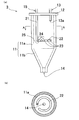
- A is a front view of the gravity sedimentation tank which concerns on embodiment of this invention
- (b) is AA sectional drawing of (a).
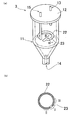
- A) is a perspective view of FIG. 2, and (b) is an enlarged cross-sectional view taken along the line BB of the slurry supply pipe shown in (a).
- (A) And (b) is the perspective view which showed the modification of the gravity sedimentation tank which concerns on this invention. It is the graph which compared the density
- FIG. 1 is a schematic view showing an apparatus for producing ashless coal using a gravity sedimentation tank according to an embodiment of the present invention.
- Ashless coal manufacturing apparatus 100 includes slurry preparation tank 1, extraction tank 2, gravity sedimentation tank 3, filtration filter 4, receiver 5, solvent recovery device 6, receiver 7, and solvent recovery device. 8 and.
- a slurry is prepared by mixing coal as a raw material and a solvent.
- the solvent-soluble component is extracted by heating the prepared slurry.
- the gravity settling tank 3 the slurry is separated into a solid concentrate containing a solvent-insoluble component and a supernatant containing a solvent-soluble component using gravity settling.
- the filtration filter 4 the supernatant liquid is filtered.
- the receiver 5 the filtered supernatant is temporarily stored.
- ashless coal is obtained by separating the solvent from the supernatant.
- the solid content concentrate is temporarily stored.
- the solvent recovery device 8 by-product charcoal is obtained by separating the solvent from the solid content concentrate.
- recovery apparatus 8 are installed as needed, and do not need to be installed.
- the solvent-insoluble component (solid content) contained in the slurry is the ash remaining without being dissolved in the solvent when the coal component is extracted with the solvent, the coal containing the ash (that is, by-product coal), etc.
- the solvent-insoluble component is derived from an organic component having a developed crosslinked structure and has a relatively large molecular weight.
- the solvent-soluble component is a coal component that can be dissolved in the solvent by extracting the coal with the solvent.
- the solvent-soluble component is derived from an organic component in coal that has not developed a crosslinked structure, and has a relatively small molecular weight.
- FIG. 2A is a front view of the gravity sedimentation tank according to the embodiment of the present invention
- FIG. 2B is a cross-sectional view taken along the line AA in FIG. 3 (a) is a perspective view of FIG. 2
- FIG. 3 (b) is a BB enlarged cross-sectional view of the slurry supply pipe shown in FIG. 3 (a).
- FIG. 2A and FIG. 3A a part of the gravity sedimentation tank is shown in a perspective view for easy understanding of the internal configuration.
- the gravity sedimentation tank 3 includes a pressure vessel 11, a lid 12, a supernatant liquid discharge pipe 13, a discharge port 14, a slurry supply pipe 15, and the like.
- the pressure vessel 11 is a vessel that separates the slurry into a solid concentrate and a supernatant, and includes a cylindrical body portion 11a and a bottom portion 11b.
- the bottom part 11b is provided on the lower end side of the body part 11a and decreases in diameter toward the lower part.
- the upper end portion of the body portion 11a is provided with a lid portion 12 that seals the upper end portion.
- drum 11a of the pressure vessel 11 is not limited to a cylindrical shape, Other shapes may be sufficient.
- the supernatant liquid discharge pipe 13 is provided for discharging the supernatant liquid accumulated in the upper part of the pressure vessel 11 from the gravity settling tank 3, extends through the lid part 12, and extends above the trunk part 11 a. Yes.
- An outlet 13a is provided at the end of the supernatant liquid discharge pipe 13, and the supernatant liquid is discharged from the outlet 13a.
- tube 13 may be penetrated by the side wall of the trunk
- the discharge port 14 is provided in order to discharge the solid concentration liquid settled in the lower part of the pressure vessel 11 from the gravity settling tank 3, and is provided in the lowermost part of the bottom part 11b. In addition, the discharge port 14 may be penetrated by the side wall of the bottom part 11b.
- the slurry supply pipe 15 is provided to supply the slurry into the pressure vessel 11 and includes a main body portion 21 and a nozzle portion 22.
- the main body 21 extends through the lid 12 and extends to the vicinity of the center (below the trunk 11a) in the height direction of the pressure vessel 11.
- the nozzle portion 22 is connected to the downstream end of the main body portion 21 and is formed in a substantially annular shape, for example, in a C shape so as to make a round in the horizontal direction along the inner wall surface of the body portion 11a (FIG. 2). (See (b)). Furthermore, the nozzle part 22 is provided with a plurality of holes 23.
- the slurry supply pipe 15 has the nozzle portion 22 and the plurality of holes 23 formed so as to extend in a substantially horizontal surface, so that the slurry can be uniformly fed into the pressure vessel 11 from the plurality of holes 23.
- the slurry can be discharged and the slurry flow can be dispersed.
- the nozzle portion 22 is formed in an annular shape, the diameter (injection diameter) of the nozzle portion 22 can be easily set in accordance with the inner diameter of the pressure vessel 11.
- the nozzle part 22 is integrally formed with the main-body part 21 by bending, it may be formed by connecting piping.
- the main body portion 21 may be provided through the side wall of the body portion 11 a and may extend from the side wall into the pressure vessel 11.
- the plurality of holes 23 are preferably provided between the outlet 13 a and the outlet 14 of the supernatant liquid discharge pipe 13.
- the hole 23 is provided above the outlet 13a of the supernatant liquid discharge pipe 13
- a large amount of solid content is contained in the supernatant liquid discharged from the outlet 13a.
- the filtration filter 4 is clogged at an early stage, and that ash is not sufficiently removed.
- the hole 23 is provided obliquely below the pipe section of the nozzle portion 22 (portion I in FIG. 3B).
- the amount of slurry discharged from all the holes 23 can be made substantially uniform.
- the hole 23 is provided directly below the pipe cross section (part II in FIG. 3B)
- the discharge amount of the slurry is larger as the hole is provided at the upstream side and decreases as the hole is at the downstream side. Therefore, it becomes difficult to uniformly discharge the slurry from all the holes 23.
- the hole 23 is provided right next to the cross section of the pipe (part III in FIG. 3 (b)), the solid content contained in the slurry gradually accumulates in the lower part of the pipe and is highly likely to cause clogging. Become.
- the holes 23 are provided at regular intervals. This is because when the holes 23 are provided at regular intervals, the slurry can be discharged more uniformly into the pressure vessel 11. Further, by increasing the number of holes 23 and reducing the opening area of the holes 23, the effect of further dispersing the slurry flow is increased. Moreover, in this embodiment, the hole 23 is provided in the outer side of the nozzle part 22 (refer Fig.3 (a)). However, whether the hole 23 is opened to the inside or outside of the nozzle portion 22 can be appropriately selected in consideration of the positional relationship between the inner wall surface of the pressure vessel 11 and the nozzle portion 22, the shape of the nozzle portion 22, and the like. There is no problem even if a hole opened inside and a hole opened outside are mixed.
- the end portion of the nozzle portion 22 has a bent portion 24 formed by being bent upward and then bent downward.
- the slurry is accumulated on the upstream side of the bent portion 24 and the pressure in the nozzle portion 22 is increased, so that the discharge amount of the slurry from the plurality of holes 23 can be made more uniform.
- a discharge port 25 is provided at the end of the nozzle portion 22, and the discharge port 25 opens downward. Thereby, for example, even when the plurality of holes 23 are blocked, the discharge port 25 serves as an escape port for the slurry, so that the slurry supply pipe 15 can be prevented from being blocked.
- the bending part 24 and the discharge outlet 25 should just be installed as needed, and do not need to provide.
- the pressure vessel 11 warm and pressurized by a heating means, a pressurizing means, etc. (not shown).
- the heat retention temperature is preferably in the range of 300 to 420 ° C.
- the pressure is preferably about 1.0 to 3.0 MPa, and more preferably 1.7 to 2.3 MPa.
- (Modification) 4 (a) and 4 (b) are perspective views showing a modified example of the gravity settling tank according to the present invention, and a slurry supply pipe having a shape different from that of the above-described embodiment is provided.
- 4 (a) and 4 (b) a part of the gravity settling tank 3 is shown in a perspective view for easy understanding of the internal configuration.
- a nozzle portion 22a is formed so as to be divided in two directions from the end of the main body portion 21a of the slurry supply pipe 15a.
- Each of the end portions of each nozzle portion 22a is provided with a bent portion 24a and a discharge port 25a.
- the two discharge ports 25a are provided at a position substantially half a circumference from the end of the main body portion 21a.
- the main body portion 21b of the slurry supply pipe 15b is penetrated in the vicinity of the approximate center of the lid portion 12b, and goes radially in four directions from the end of the main body portion 21b.
- a nozzle portion 22b is formed.
- Each end portion of the nozzle portion 22a is provided with a bent portion 24b and a hole (discharge port) 25b.
- the nozzle part 22b is not restricted to the structure which goes to 4 directions, and does not need to be radial.
- the method for producing ashless coal according to the present invention includes a slurry preparation step, an extraction step, a separation step, and an ashless coal acquisition step, and further includes a byproduct coal acquisition step as necessary.
- the slurry preparation step is a step of preparing a slurry by mixing coal and a solvent, and is performed in the slurry preparation tank 1.
- a wide variety of quality coal can be used as the coal raw material, and for example, bituminous coal, subbituminous coal, lignite, and the like are preferably used.
- the solvent is not particularly limited as long as it dissolves coal, but a bicyclic aromatic compound derived from coal is preferably used. Since the basic structure of this bicyclic aromatic compound is similar to that of coal, it has a high affinity with coal. Therefore, when a bicyclic aromatic compound is used as a solvent, a relatively high extraction rate is obtained. Obtainable.
- the bicyclic aromatic compound derived from coal include methyl naphthalene oil and naphthalene oil, which are distilled oils of by-products when carbon is produced by carbonization to produce coke.
- the boiling point of the solvent is not particularly limited. However, for example, from the viewpoint of the extraction rate in the extraction step and the solvent recovery rate in the ashless coal acquisition step, a solvent having a boiling point of 180 to 300 ° C., particularly 230 to 280 ° C. is preferably used.
- the concentration of the coal raw material with respect to the solvent is not particularly limited, but is preferably in the range of 10 to 50 wt%, more preferably in the range of 15 to 35 wt% on the basis of dry coal.
- the extraction step is a step of heating the slurry obtained in the slurry preparation step to extract solvent-soluble components, and is performed in the extraction tank 2.
- the slurry prepared in the slurry preparation tank 1 is supplied to the extraction tank 2 by a pump or the like, and is heated and held at a predetermined temperature while being stirred by a stirrer provided in the extraction tank 2. Extraction is performed in this way.
- the slurry may be once supplied to a preheater (not shown) and heated to a predetermined temperature, and then supplied to the extraction tank 2.
- the heating temperature of the slurry in the extraction step is not particularly limited as long as the solvent-soluble component can be dissolved.
- the heating temperature is preferably in the range of 300 to 420 ° C., more preferably in the range of 350 to 400 ° C., for example, from the viewpoint of sufficient extraction of solvent-soluble components.
- the heating time (extraction time) is not particularly limited, but is preferably in the range of 5 to 60 minutes, more preferably in the range of 20 to 40 minutes from the viewpoint of sufficient dissolution and extraction rate.
- the heating time is the sum of the heating time in the preheater and the heating time in the extraction tank 2.
- the extraction step is preferably performed in the presence of an inert gas, and inexpensive nitrogen is preferably used.
- the pressure in the extraction step is preferably in the range of 1.0 to 2.0 MPa, although it depends on the temperature at the time of extraction and the vapor pressure of the solvent used.
- the separation step is a step of separating the slurry obtained in the extraction step into a solid concentrate and a supernatant using the gravity sedimentation tank 3 described above.
- the supernatant is a solution portion in which a solvent-soluble component is dissolved
- the solid content concentrate is a slurry portion containing a solvent-insoluble component.
- the supernatant liquid discharged from the gravity sedimentation tank 3 is filtered by the filtration filter 4, temporarily stored in the receiver 5, and supplied to the solvent recovery device 6.
- the solid concentrate is temporarily stored in the receiver 7 and then supplied to the solvent recovery device 8.
- the ashless charcoal acquisition step is a step of obtaining ashless charcoal by separating the solvent from the supernatant liquid separated in the separation step, and is performed by the solvent recovery device 6.
- Ashless charcoal has an ash concentration of 3% or less, hardly contains ash, does not contain any moisture, and exhibits a higher calorific value than, for example, raw coal. Furthermore, ashless coal has significantly improved softening and melting property, which is a particularly important quality as a raw material for iron-making coke, and thus exhibits performance (fluidity) far superior to, for example, raw coal. Therefore, ashless coal can be used as a blended coal for coke raw materials. Moreover, ashless coal can also be used as a coal blend by mixing with the byproduct coal mentioned later.
- the byproduct charcoal acquisition step is a step of obtaining a byproduct charcoal by separating the solvent from the solid concentrate separated in the separation step, and is performed by the solvent recovery device 8 as necessary.
- a general distillation method or evaporation method can be used as in the above-described ashless coal acquisition step.
- the solvent recovered by separation can be repeatedly used by circulating it to the slurry preparation tank 1.
- by-product charcoal in which solvent-insoluble components including ash and the like are concentrated can be obtained from the solid concentrate.
- By-product charcoal contains ash, but does not contain water at all, and has a sufficient calorific value.
- By-product charcoal does not exhibit softening and melting properties.
- the oxygen-containing functional group is eliminated from the by-product coal, the by-product coal does not inhibit the softening and melting properties of other coals contained in this blend coal when used as a blend coal. Therefore, this by-product coal can be used as a part of coke feed coal as well as normal non-coking coal, and can also be used for various fuels without coke feed coal. It is.
- the by-product coal may be discarded without being collected.
- the method for producing ashless coal according to the present invention is as described above. However, in carrying out the present invention, for example, a coal pulverization step for pulverizing a coal raw material, or a removal step for removing unnecessary substances such as dust, before or after each step within a range that does not adversely affect the respective steps. In addition, other steps such as a drying step of drying the obtained ashless coal may be included.
- Bituminous coal is used as a coal raw material, and methylnaphthalene H (C-Chem Co., Ltd) is used as a solvent.
- a slurry is prepared by mixing the coal and the solvent.
- concentration of the coal raw material with respect to a solvent is 19.5 wt% on a dry coal basis.
- the slurry was heated to 400 ° C. and 2.0 MPa, and extraction of solvent-soluble components was performed for 20 minutes. And this slurry was supplied to the gravity settling tank hold
- a pressure vessel the pressure vessel which has the structure similar to the pressure vessel 11 shown in FIG. 1 is used.
- tube B which has the structure similar to the slurry supply pipe
- the slurry supply pipe A has only one hole (discharge port) at the end, whereas the slurry supply pipe B has a plurality of holes (discharge ports) in the nozzle portion.
- the slurry supply pipes A and B are both extended to a height of H 0 ⁇ 0.6 with respect to the height H 0 of the pressure vessel.
- FIG. 5 shows the result of measuring the concentration of the solid content in the pressure vessel while supplying the slurry for 40 hours in the pressure vessel and continuing to supply the slurry.
- slurry preparation tank 2 extraction tank 3: gravity settling tank 4: filtration filter 5, 7: receiver 6, 8: solvent recovery device 11: pressure vessel 12: lid 13: supernatant liquid discharge pipe 14: discharge port 15 : Slurry supply pipe 21: Main body part 22: Nozzle part 23: Hole 24: Bending part 25: Discharge port 100: Ashless coal production apparatus
Landscapes
- Chemical & Material Sciences (AREA)
- Chemical Kinetics & Catalysis (AREA)
- Oil, Petroleum & Natural Gas (AREA)
- Organic Chemistry (AREA)
- Engineering & Computer Science (AREA)
- Combustion & Propulsion (AREA)
- General Chemical & Material Sciences (AREA)
- Solid Fuels And Fuel-Associated Substances (AREA)
Abstract
Description
また、スラリーを固形分濃縮液と上澄み液とに効率的に分離する方式として重力沈降法を用いる、重力沈降槽が知られている(例えば、特許文献2、3)。
スラリー調製槽1では、原料となる石炭と溶剤とを混合することにより、スラリーが調製される。抽出槽2では、調製されたスラリーを加熱することにより、溶剤可溶成分が抽出される。重力沈降槽3では、重力沈降を利用して、スラリーが、溶剤不溶成分を含んだ固形分濃縮液と溶剤可溶成分を含んだ上澄み液とに分離される。濾過フィルター4では、上澄み液が濾過される。受器5では、濾過された上澄み液が一旦貯留される。溶剤回収装置6では、上澄み液から溶剤を分離することにより、無灰炭が得られる。受器7では、固形分濃縮液が一旦貯留される。溶剤回収装置8では、固形分濃縮液から溶剤を分離することにより、副生炭が得られる。
なお、濾過フィルター4、受器7および溶剤回収装置8は、必要に応じて設置されるものであり、設置されていなくてもよい。
次に、本発明の実施形態に係る重力沈降槽3について説明する。図2(a)は、本発明の実施形態に係る重力沈降槽の正面図であり、図2(b)は(a)のA-A断面図である。また、図3(a)は、図2の斜視図であり、図3(b)は(a)に示したスラリー供給管のB-B拡大断面図である。なお、図2(a)および図3(a)においては、内部構成の理解を容易とするため、重力沈降槽の一部を透視的に図示している。図2(a)に示すように、重力沈降槽3は、圧力容器11、蓋部12、上澄み液排出管13、排出口14、スラリー供給管15などを備えている。
圧力容器11は、スラリーを固形分濃縮液と上澄み液とに分離する容器であり、円筒状の胴部11aと、底部11bと、からなる。底部11bは、胴部11aの下端側に設けられており、下部に向かうにつれて縮径する。胴部11aの上端部には、この上端部を密閉する蓋部12が備えられている。なお、圧力容器11の胴部11aは円筒形状に限定されるものではなく、他の形状であってもよい。
上澄み液排出管13は、圧力容器11の上部に溜まった上澄み液を重力沈降槽3から排出するために備えられており、蓋部12に貫設され、胴部11aの上方まで延設されている。上澄み液排出管13の末端には流出口13aが設けられ、この流出口13aから上澄み液が排出される。なお、上澄み液排出管13は、胴部11aの側壁に貫設されていてもよい。
排出口14は、圧力容器11の下部に沈降した固形分濃縮液を重力沈降槽3から排出するために備えられており、底部11bの最下部に設けられている。なお、排出口14は、底部11bの側壁に貫設されていてもよい。
スラリー供給管15は、圧力容器11内にスラリーを供給するために備えられており、本体部21とノズル部22とからなる。本体部21は、蓋部12に貫設され、圧力容器11の高さ方向において中央付近(胴部11aの下方)まで延設されている。ノズル部22は、本体部21の下流側の末端に接続され、胴部11aの内壁面に沿って水平方向に略一周するように略環状に、例えばC字状に形成されている(図2(b)参照)。さらに、ノズル部22には、複数の孔23が設けられている。このように、スラリー供給管15は、略水平方向面に延在するように形成されたノズル部22と複数の孔23とを有するので、スラリーを複数の孔23から圧力容器11内に均一に吐出することができ、スラリーの流れを分散させることが可能となる。その結果、底部に沈降した固形分濃縮液が攪拌されることを抑止することができる。また、ノズル部22が環状に形成されているので、圧力容器11の内径に合わせてノズル部22の径(噴射径)が容易に設定可能である。なお、ノズル部22は、曲げ加工により本体部21と一体に形成されているが、配管をつなぎ合わせることにより形成されていてもよい。また、本体部21は、胴部11aの側壁に貫設され、当該側壁から圧力容器11内に延設されていてもよい。
図4(a)(b)は、本発明に係る重力沈降槽の変形例を示した斜視図であり、上述した実施形態とは形状が異なるスラリー供給管が備えられている。なお、図4(a)(b)においては、内部構成の理解を容易とするため重力沈降槽3の一部を透視的に図示している。図4(a)に示した重力沈降槽3aにおいては、スラリー供給管15aの本体部21aの末端から2方向に分かれるようにノズル部22aが形成されている。各ノズル部22aの末端部のそれぞれには、屈曲部24aおよび吐出口25aが設けられている。なお、2つの吐出口25aは、本体部21aの末端から略半周した位置に設けられている。図4(b)に示した重力沈降槽3bにおいては、スラリー供給管15bの本体部21bが蓋部12bの略中央付近に貫設され、本体部21bの末端から放射状に、4方向へと向かうノズル部22bが形成されている。ノズル部22aの各々の末端部には、それぞれ屈曲部24bと孔(吐出口)25bとが設けられている。なお、ノズル部22bは、4方向へと向かう構成に限られず、また放射状でなくてもよい。
次に、無灰炭の製造方法について説明する。本発明に係る無灰炭の製造方法は、スラリー調製工程、抽出工程、分離工程、および無灰炭取得工程を備え、必要に応じて副生炭取得工程をさらに備える。
スラリー調製工程は、石炭と溶剤とを混合してスラリーを調製する工程であり、スラリー調製槽1で行われる。石炭原料としては、幅広い品質の石炭を使用することができ、例えば、瀝青炭、亜瀝青炭、褐炭等が好適に用いられる。
抽出工程は、スラリー調製工程で得られたスラリーを加熱して、溶剤可溶成分を抽出する工程であり、抽出槽2で行われる。スラリー調製槽1で調製されたスラリーは、ポンプ等によって、抽出槽2に供給され、抽出槽2に設けられた攪拌機で攪拌されながら所定温度に加熱保持される。このようにして抽出が行われる。なお、スラリーは、一旦予熱器(不図示)に供給されて所定温度まで加熱された後、抽出槽2に供給されてもよい。
分離工程は、抽出工程で得られたスラリーから、上述した重力沈降槽3を用いて、固形分濃縮液と上澄み液とに分離する工程である。上澄み液は溶剤可溶成分が溶解された溶液部分であり、固形分濃縮液は溶剤不溶成分を含むスラリー部分である。当該分離工程においては、上述した重力沈降槽3が用いられるので、固形分が十分に除去された上澄み液が得られる。重力沈降槽3から排出された上澄み液は、濾過フィルター4で濾過された後、一旦受器5に貯留され、溶剤回収装置6へ供給される。一方、固形分濃縮液は、一旦受器7に貯留された後、溶剤回収装置8へ供給される。
無灰炭取得工程は、分離工程で分離された上澄み液から溶剤を分離して無灰炭を得る工程であり、溶剤回収装置6で行われる。
副生炭取得工程は、前記分離工程で分離された固形分濃縮液から溶剤を分離して副生炭を得る工程であり、必要に応じて、溶剤回収装置8で実施される。
本発明に係る無灰炭の製造方法においては、上述した重力沈降槽3を用いることにより、固形分が十分除去された上澄み液を得ることができ、効率よく無灰炭を製造することができる。また、濾過フィルター4が早期に詰まってしまうことも防止できる。
本発明に係る重力沈降槽の効果を確認するため、図1に示した本発明に係る重力沈降槽3と同様の構成を有する重力沈降槽と、従来の重力沈降槽と、を用いて実験を行った。この実験では、固形分と上澄み液とに分離した後の圧力容器内の固形分の濃度分布が、上記した2つの重力沈降槽について各々測定、比較される。
2:抽出槽
3:重力沈降槽
4:濾過フィルター
5、7:受器
6、8:溶剤回収装置
11:圧力容器
12:蓋部
13:上澄み液排出管
14:排出口
15:スラリー供給管
21:本体部
22:ノズル部
23:孔
24:屈曲部
25:吐出口
100:無灰炭製造装置
Claims (5)
- 石炭と溶剤とを混合したスラリーに含まれる固形分を沈降させて固形分濃縮液と上澄み液とに分離する圧力容器と、前記圧力容器に前記スラリーを供給する供給管と、を備えた重力沈降槽であって、
前記供給管は、本体部と、前記本体部の下流側に接続され水平方向に延在するノズル部と、を有し、
前記ノズル部には複数の孔が設けられていることを特徴とする重力沈降槽。 - 前記複数の孔は、前記スラリーが水平方向に対して斜め下方に向かって前記複数の孔から噴出するような位置に設けられていることを特徴とする請求項1に記載の重力沈降槽。
- 前記圧力容器が円筒状であり、
前記ノズル部が前記圧力容器の内壁面に沿って環状に形成されていることを特徴とする請求項1に記載の重力沈降槽。 - 前記ノズル部は、上方に折り曲げられた部分と、前記上方に折り曲げられた部分の下流側で下方に折り曲げられた部分と、から形成された屈曲部を末端に有し、
前記ノズル部の前記末端に吐出口が設けられていることを特徴とする請求項1に記載の重力沈降槽。 - 石炭と溶剤とを混合してスラリーを調製するスラリー調製工程と、
前記スラリー調製工程で得られたスラリーを加熱して溶剤可溶成分を抽出する抽出工程と、
前記抽出工程で得られたスラリーを、請求項1~4のいずれか1項に記載の重力沈降槽により、固形分濃縮液と上澄み液とに分離する分離工程と、
前記分離工程で分離された前記上澄み液から前記溶剤を分離して無灰炭を得る無灰炭取得工程と、を備えることを特徴とする無灰炭の製造方法。
Priority Applications (4)
| Application Number | Priority Date | Filing Date | Title |
|---|---|---|---|
| AU2012274309A AU2012274309B2 (en) | 2011-06-22 | 2012-06-22 | Gravitational settling tank and ashless coal manufacturing method |
| CN201280030156.3A CN103635563B (zh) | 2011-06-22 | 2012-06-22 | 重力沉降槽以及无灰煤的制造方法 |
| US14/123,887 US9315751B2 (en) | 2011-06-22 | 2012-06-22 | Gravitational settling tank and method for producing ash-free coal |
| KR1020137033615A KR101559226B1 (ko) | 2011-06-22 | 2012-06-22 | 중력 침강조 및 무회탄의 제조 방법 |
Applications Claiming Priority (2)
| Application Number | Priority Date | Filing Date | Title |
|---|---|---|---|
| JP2011-138094 | 2011-06-22 | ||
| JP2011138094A JP5634950B2 (ja) | 2011-06-22 | 2011-06-22 | 重力沈降槽および無灰炭の製造方法 |
Publications (1)
| Publication Number | Publication Date |
|---|---|
| WO2012176893A1 true WO2012176893A1 (ja) | 2012-12-27 |
Family
ID=47422720
Family Applications (1)
| Application Number | Title | Priority Date | Filing Date |
|---|---|---|---|
| PCT/JP2012/066043 Ceased WO2012176893A1 (ja) | 2011-06-22 | 2012-06-22 | 重力沈降槽および無灰炭の製造方法 |
Country Status (6)
| Country | Link |
|---|---|
| US (1) | US9315751B2 (ja) |
| JP (1) | JP5634950B2 (ja) |
| KR (1) | KR101559226B1 (ja) |
| CN (1) | CN103635563B (ja) |
| AU (1) | AU2012274309B2 (ja) |
| WO (1) | WO2012176893A1 (ja) |
Cited By (2)
| Publication number | Priority date | Publication date | Assignee | Title |
|---|---|---|---|---|
| JP2014172017A (ja) * | 2013-03-12 | 2014-09-22 | Kobe Steel Ltd | 重力沈降槽および無灰炭の製造方法 |
| WO2017122459A1 (ja) * | 2016-01-13 | 2017-07-20 | 株式会社神戸製鋼所 | 無灰炭の製造方法 |
Families Citing this family (2)
| Publication number | Priority date | Publication date | Assignee | Title |
|---|---|---|---|---|
| JP5653339B2 (ja) * | 2011-12-28 | 2015-01-14 | 株式会社神戸製鋼所 | 重力沈降槽およびこれを用いた無灰炭の製造方法 |
| JP6309438B2 (ja) * | 2014-12-03 | 2018-04-11 | 株式会社神戸製鋼所 | 分離装置 |
Citations (3)
| Publication number | Priority date | Publication date | Assignee | Title |
|---|---|---|---|---|
| JPS62269719A (ja) * | 1986-05-16 | 1987-11-24 | Chubu Bandou Kk | 沈澱槽における汚泥の沈澱分離方法 |
| JPH0760009A (ja) * | 1993-06-16 | 1995-03-07 | Sumitomo Chem Co Ltd | 沈降式固液分離装置 |
| JP2009214000A (ja) * | 2008-03-10 | 2009-09-24 | Kobe Steel Ltd | 固液分離装置、固液分離方法および無灰炭の製造方法 |
Family Cites Families (6)
| Publication number | Priority date | Publication date | Assignee | Title |
|---|---|---|---|---|
| US5833865A (en) * | 1993-06-16 | 1998-11-10 | Sumitomo Chemical Company, Limited | Sedimentation type solid-liquid separator |
| CA2267677C (en) * | 1999-03-31 | 2006-09-19 | Np Industries Inc. | Fluid treatment system |
| JP4537268B2 (ja) | 2005-06-22 | 2010-09-01 | 株式会社神戸製鋼所 | 重力沈降槽 |
| JP4061351B1 (ja) * | 2006-10-12 | 2008-03-19 | 株式会社神戸製鋼所 | 無灰炭の製造方法 |
| CN201098612Y (zh) | 2007-08-22 | 2008-08-13 | 中国石油化工股份有限公司 | 一种反应器的进料分布器 |
| JP5334433B2 (ja) | 2008-03-19 | 2013-11-06 | 株式会社神戸製鋼所 | 無灰炭の製造方法 |
-
2011
- 2011-06-22 JP JP2011138094A patent/JP5634950B2/ja active Active
-
2012
- 2012-06-22 KR KR1020137033615A patent/KR101559226B1/ko active Active
- 2012-06-22 US US14/123,887 patent/US9315751B2/en not_active Expired - Fee Related
- 2012-06-22 WO PCT/JP2012/066043 patent/WO2012176893A1/ja not_active Ceased
- 2012-06-22 AU AU2012274309A patent/AU2012274309B2/en not_active Ceased
- 2012-06-22 CN CN201280030156.3A patent/CN103635563B/zh active Active
Patent Citations (3)
| Publication number | Priority date | Publication date | Assignee | Title |
|---|---|---|---|---|
| JPS62269719A (ja) * | 1986-05-16 | 1987-11-24 | Chubu Bandou Kk | 沈澱槽における汚泥の沈澱分離方法 |
| JPH0760009A (ja) * | 1993-06-16 | 1995-03-07 | Sumitomo Chem Co Ltd | 沈降式固液分離装置 |
| JP2009214000A (ja) * | 2008-03-10 | 2009-09-24 | Kobe Steel Ltd | 固液分離装置、固液分離方法および無灰炭の製造方法 |
Cited By (2)
| Publication number | Priority date | Publication date | Assignee | Title |
|---|---|---|---|---|
| JP2014172017A (ja) * | 2013-03-12 | 2014-09-22 | Kobe Steel Ltd | 重力沈降槽および無灰炭の製造方法 |
| WO2017122459A1 (ja) * | 2016-01-13 | 2017-07-20 | 株式会社神戸製鋼所 | 無灰炭の製造方法 |
Also Published As
| Publication number | Publication date |
|---|---|
| CN103635563A (zh) | 2014-03-12 |
| JP2013001900A (ja) | 2013-01-07 |
| JP5634950B2 (ja) | 2014-12-03 |
| KR101559226B1 (ko) | 2015-10-13 |
| KR20140022918A (ko) | 2014-02-25 |
| US9315751B2 (en) | 2016-04-19 |
| US20140115957A1 (en) | 2014-05-01 |
| AU2012274309B2 (en) | 2015-06-11 |
| AU2012274309A1 (en) | 2014-01-16 |
| CN103635563B (zh) | 2015-11-25 |
Similar Documents
| Publication | Publication Date | Title |
|---|---|---|
| JP5334433B2 (ja) | 無灰炭の製造方法 | |
| JP2005120185A (ja) | 無灰炭の製造方法 | |
| JP5634950B2 (ja) | 重力沈降槽および無灰炭の製造方法 | |
| WO2013099650A1 (ja) | 無灰炭の製造方法 | |
| JP4939466B2 (ja) | 固液分離装置、固液分離方法および無灰炭の製造方法 | |
| CN103254933B (zh) | 从煤直接液化残渣中分离液化重质油和沥青类物质的方法 | |
| JP5259216B2 (ja) | 無灰炭の製造方法 | |
| JP4971955B2 (ja) | 無灰炭の製造方法 | |
| AU2006218346B2 (en) | Method and apparatus for manufacturing solid fuel from raw material coal | |
| JP5990501B2 (ja) | 無灰炭の製造方法 | |
| JP5722208B2 (ja) | 無灰炭の製造方法 | |
| AU2016230455B2 (en) | Method for manufacturing ashless coal | |
| JP6105334B2 (ja) | 重力沈降槽および無灰炭の製造方法 | |
| JP6309438B2 (ja) | 分離装置 | |
| JP6017337B2 (ja) | 無灰炭の製造方法 | |
| KR102078216B1 (ko) | 무회탄의 제조 방법 | |
| JP2014189740A (ja) | 無灰炭の製造装置および無灰炭の製造方法 | |
| JP2013136692A (ja) | 無灰炭の製造方法 |
Legal Events
| Date | Code | Title | Description |
|---|---|---|---|
| 121 | Ep: the epo has been informed by wipo that ep was designated in this application |
Ref document number: 12802863 Country of ref document: EP Kind code of ref document: A1 |
|
| WWE | Wipo information: entry into national phase |
Ref document number: 14123887 Country of ref document: US |
|
| ENP | Entry into the national phase |
Ref document number: 20137033615 Country of ref document: KR Kind code of ref document: A |
|
| NENP | Non-entry into the national phase |
Ref country code: DE |
|
| ENP | Entry into the national phase |
Ref document number: 2012274309 Country of ref document: AU Date of ref document: 20120622 Kind code of ref document: A |
|
| 122 | Ep: pct application non-entry in european phase |
Ref document number: 12802863 Country of ref document: EP Kind code of ref document: A1 |