WO2012176872A1 - クリップ付ワイヤハーネス - Google Patents
クリップ付ワイヤハーネス Download PDFInfo
- Publication number
- WO2012176872A1 WO2012176872A1 PCT/JP2012/065977 JP2012065977W WO2012176872A1 WO 2012176872 A1 WO2012176872 A1 WO 2012176872A1 JP 2012065977 W JP2012065977 W JP 2012065977W WO 2012176872 A1 WO2012176872 A1 WO 2012176872A1
- Authority
- WO
- WIPO (PCT)
- Prior art keywords
- clip
- wire harness
- panel
- mounting hole
- wire
- Prior art date
- Legal status (The legal status is an assumption and is not a legal conclusion. Google has not performed a legal analysis and makes no representation as to the accuracy of the status listed.)
- Ceased
Links
Images




Classifications
-
- B—PERFORMING OPERATIONS; TRANSPORTING
- B60—VEHICLES IN GENERAL
- B60R—VEHICLES, VEHICLE FITTINGS, OR VEHICLE PARTS, NOT OTHERWISE PROVIDED FOR
- B60R16/00—Electric or fluid circuits specially adapted for vehicles and not otherwise provided for; Arrangement of elements of electric or fluid circuits specially adapted for vehicles and not otherwise provided for
- B60R16/02—Electric or fluid circuits specially adapted for vehicles and not otherwise provided for; Arrangement of elements of electric or fluid circuits specially adapted for vehicles and not otherwise provided for electric constitutive elements
- B60R16/0207—Wire harnesses
- B60R16/0215—Protecting, fastening and routing means therefor
-
- F—MECHANICAL ENGINEERING; LIGHTING; HEATING; WEAPONS; BLASTING
- F16—ENGINEERING ELEMENTS AND UNITS; GENERAL MEASURES FOR PRODUCING AND MAINTAINING EFFECTIVE FUNCTIONING OF MACHINES OR INSTALLATIONS; THERMAL INSULATION IN GENERAL
- F16B—DEVICES FOR FASTENING OR SECURING CONSTRUCTIONAL ELEMENTS OR MACHINE PARTS TOGETHER, e.g. NAILS, BOLTS, CIRCLIPS, CLAMPS, CLIPS OR WEDGES; JOINTS OR JOINTING
- F16B9/00—Connections of rods or tubular parts to flat surfaces at an angle
- F16B9/05—Connections of rods or tubular parts to flat surfaces at an angle by way of an intermediate member
- F16B9/056—Connections of rods or tubular parts to flat surfaces at an angle by way of an intermediate member the intermediate member extending through the flat surface; the rod or tubular part extending through the flat surface
-
- F—MECHANICAL ENGINEERING; LIGHTING; HEATING; WEAPONS; BLASTING
- F16—ENGINEERING ELEMENTS AND UNITS; GENERAL MEASURES FOR PRODUCING AND MAINTAINING EFFECTIVE FUNCTIONING OF MACHINES OR INSTALLATIONS; THERMAL INSULATION IN GENERAL
- F16L—PIPES; JOINTS OR FITTINGS FOR PIPES; SUPPORTS FOR PIPES, CABLES OR PROTECTIVE TUBING; MEANS FOR THERMAL INSULATION IN GENERAL
- F16L5/00—Devices for use where pipes, cables or protective tubing pass through walls or partitions
- F16L5/02—Sealing
- F16L5/027—Sealing by means of a joint of the quick-acting type
-
- H—ELECTRICITY
- H02—GENERATION; CONVERSION OR DISTRIBUTION OF ELECTRIC POWER
- H02G—INSTALLATION OF ELECTRIC CABLES OR LINES, OR OF COMBINED OPTICAL AND ELECTRIC CABLES OR LINES
- H02G3/00—Installations of electric cables or lines or protective tubing therefor in or on buildings, equivalent structures or vehicles
- H02G3/22—Installations of cables or lines through walls, floors or ceilings, e.g. into buildings
-
- F16B9/023—
-
- H—ELECTRICITY
- H01—ELECTRIC ELEMENTS
- H01B—CABLES; CONDUCTORS; INSULATORS; SELECTION OF MATERIALS FOR THEIR CONDUCTIVE, INSULATING OR DIELECTRIC PROPERTIES
- H01B7/00—Insulated conductors or cables characterised by their form
- H01B7/40—Insulated conductors or cables characterised by their form with arrangements for facilitating mounting or securing
Definitions
- the present invention relates to a wire harness with a clip in which a clip formed so as to be able to be locked with a mounting hole of a panel is integrally formed with an electric wire inserted through the mounting hole.
- Cars are equipped with various electronic devices and electrical components.
- a wire harness is used as means for transmitting electric power from a power source such as a battery or a control signal from a control device to these electronic devices and electrical components.
- the wire harness is routed in the required routing form on a panel that forms the body of an automobile or the like.
- the grommet is fitted into the mounting hole of the inner panel of the back door, and the grommet insertion hole fitted into the mounting hole is inserted.
- the wire harness is inserted and routed.
- various types in which a grommet is fitted to a panel and a wire harness is routed have been proposed (see, for example, Patent Documents 1 to 3).
- the wire harness has a rubber grommet that exhibits an excellent water stop function, but it is excessive to use the grommet in a place where the water stop function is unnecessary because the water naturally drains out, such as the back door. It has become a performance. Furthermore, since rubber grommets are relatively expensive, the manufacturing cost of the wire harness increases.
- the grommet latched by the mounting hole of a panel is formed of the synthetic resin which does not have elasticity or elasticity, the insertion hole is larger diameter than the external shape of a wire harness.
- the grommet is enlarged.
- the insertion hole has a larger diameter than the outer shape of the wire harness, the outer appearance of the grommet is not good.
- the grommet Since the grommet is composed of a plurality of members, the number of parts of the grommet increases and the wire harness becomes expensive. In addition, the structure becomes complicated and the time required for the assembly work becomes longer. Further, after assembling the grommet, it is necessary to insert the wire harness into the insertion hole. Further, since the locking blade protrudes outward and is exposed, the locking blade may be damaged.
- an object of the present invention is to provide a wire harness with a clip in which a clip formed so as to be able to be locked with a mounting hole of a panel is integrally formed with an electric wire inserted through the mounting hole.
- the invention described in claim 1 is a wire harness with a clip in which a clip to be locked to a mounting hole of a panel is integrally formed with an electric wire, and the clip is , A dish-shaped part that is superimposed on the mounting hole and is in contact with the panel; a main body part that is erected from the dish-shaped part and is inserted into the mounting hole; and a peripheral part of the mounting hole.
- a wire harness with a clip, wherein the wire is provided so as to penetrate through the dish-like portion and the main body portion.
- the invention described in claim 2 is the wire harness with clip according to claim 1, wherein the dish-shaped portion is provided with a recess in a surface facing the panel.
- the clip-attached wire harness is locked to the mounting hole only by inserting the clip through the mounting hole of the panel. For this reason, the wire harness with a clip can be attached to the attachment hole of the panel more easily and more quickly than the conventional grommet. Therefore, the work time for attaching the wire harness with clip to the panel is shortened.
- the clip-attached wire harness is formed by integrally forming the clip on the electric wire, the step of assembling the clip, the step of fixing the clip to the electric wire, and the like are omitted. Time is shortened.
- the wire harness with a clip does not require the insertion hole of the electric wire provided in the conventional grommet, the hole diameter of the mounting hole of the panel is minimized and the clip is miniaturized. For this reason, it becomes a favorable external appearance.
- the wire harness with a clip is made of a synthetic resin that is cheaper than rubber or the like, it becomes cheaper than a wire harness using a conventional grommet.
- the free end of the locking piece since the free end of the locking piece does not come into contact with the dish-shaped portion due to the recess provided in the dish-shaped portion, the free end of the locking piece Are closer to each other and are securely locked to the peripheral edge portion and the inner peripheral surface of the mounting hole of the panel, and the dish-like portion is brought into contact with the panel. For this reason, the wire harness with a clip is reliably prevented from rattling in the axial direction of the electric wire.
- FIG. 1 It is a perspective view of the wire harness with a clip concerning one embodiment of the present invention. It is a top view of the wire harness with a clip shown in FIG. It is a principal part expanded sectional view of the metal mold
- a wire harness 1 includes an electric wire 3 inserted into an attachment hole 13 of a panel 12 and a clip 2 formed to be able to be locked in the attachment hole 13.
- the clip 2 is formed integrally with the electric wire 3.
- the electric wire 3 has the electroconductive core wire 3a and the insulating coating
- the core wire 3a is formed by twisting conductive wires made of a plurality of metals.
- the covering portion 3b covers the core wire 3a and is made of a synthetic resin such as a polyvinyl chloride resin. For this reason, the outer surface of the electric wire 3 is the outer surface of the said coating
- the electric wire 3 may be a wire bundle in which a plurality of electric wires 3 are bundled, or a wire bundle in which a plurality of electric wires 3 are bundled with a tape for wire harness, a binding band, or the like.
- the core wire 3a may be comprised from one core wire.
- the clip 2 is provided on the same axis as the electric wire 3 as shown in FIG.
- the clip 2 is formed integrally with the electric wire 3.
- the clip 2 is formed of a synthetic resin such as a polypropylene resin having flexibility.
- the clip 2 includes a plate-like portion 4 that contacts the surface of the panel when the clip 2 is overlaid on the mounting hole 13, a main body portion 5 that extends from the plate-like portion 4 along the electric wire 3, and the main body portion. 5 and a pair of locking pieces 6 extending toward the dish-like portion 4.
- the main body 5 is provided coaxially with the electric wire 3 as the center, as shown in FIGS.
- the main body 5 is formed integrally with the outer surface of the electric wire 3.
- the main body portion 5 is provided with a bulging portion whose tip portion is formed in an arc shape along the shape of the inner peripheral surface of the mounting hole 13. For this reason, when the clip-attached wire harness 1 is locked in the mounting hole 13, rattling of the clip 2 in a direction orthogonal to the longitudinal direction of the electric wire 3 is prevented.
- the pair of locking pieces 6 are erected from both side surfaces of the main body portion 5 and extended toward the dish-shaped portion 4. As shown in FIG. 2, the locking pieces 6 are formed so as to be gradually separated from each other toward the dish-like portion 4.
- the locking piece 6 is formed to be swingable, and the swinging direction of the locking piece 6 is formed in a direction perpendicular to the longitudinal direction of the electric wire 3.
- the dish-shaped portion 4 includes a recess 8 that prevents the free end of the locking piece from contacting the dish-shaped portion 4 when the locking piece 6 swings.
- the recess 8 is formed in a groove shape on the surface of the dish-like portion 4 facing the panel.
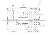
- the mold 21 in which the above-described wire harness 1 with a clip is molded is a horizontal split mold as shown in FIG. 3, and includes an upper mold 22 and a lower mold 23.
- the upper mold 22 and the lower mold 23 are each provided with a linear cavity 25 formed along the outer shape of the electric wire 3 and a clip cavity 24 formed along the outer shape of the clip 2.
- the lower mold 23 has a linear cavity 25 and a clip cavity 24 formed upward.
- the linear cavity 25 is provided with outlets 26 through which the electric wires 3 are led out from both ends of the upper mold 22 and the lower mold 23.
- the mold 21 may be a vertical split mold.
- the die 21 may be provided with a plurality of the clip cavities 24 on the filament cavities 25.
- the mold 21 in this case has a plurality of clip cavities 24 at positions where the plurality of clips 2 can be locked in the mounting holes 13 of the panel 12 when the clip-attached wire harness 1 is attached to the panel 12. Placed in. That is, the plurality of clips 2 are provided at positions where the relative positions with respect to the electric wires 3 can be locked in the mounting holes 13 of the panel 12.
- the plurality of clips 2 are provided at positions where the relative positions with respect to the electric wires 3 can be locked in the mounting holes 13 of the panel 12.
- the relative positions of the plurality of clips 2 with respect to the electric wires 3 are Excluding errors that occur during injection molding, it means that the position is determined at the time of design.
- each free end of a pair of locking piece 6 will be elastically deformed in the direction which mutually adjoins. At this time, the respective free ends of the pair of locking pieces 6 are accommodated in the recesses 8 of the dish-like portion 4.
- each free end of the locking piece 6 is locked to the peripheral edge of the mounting hole 13 in a state where the dish-shaped portion 4 is in contact with the panel 12.
- the respective free ends are locked to the inner peripheral surface of the mounting hole 13, rattling of the clip 2 with respect to the longitudinal direction of the electric wire 3 is prevented, and the clip 2 and the mounting hole 13 Is securely locked.
- the clip 2 to be locked in the mounting hole 13 of the panel 12 is integrally formed with the electric wire 3.
- the clip 2 is overlapped with the mounting hole 13 and abutted against the panel 12, the main body 5 erected from the dish-shaped portion 4 and inserted into the mounting hole 13, A locking piece 6 that is locked to the peripheral edge of the mounting hole 13, and the electric wire 3 is provided through the dish-like portion 4 and the main body portion 5.
- the dish-like portion 4 is provided with a recess 8 in which the free end of the locking piece 6 is accommodated.
- the clip-attached wire harness 1 is locked to the attachment hole 13 only by inserting the clip 2 through the attachment hole 13 of the panel 12. For this reason, the wire harness 1 with a clip can be attached to the attachment hole 13 of the panel 12 more easily and more quickly than a wire harness having a conventional grommet.
- the clip-attached wire harness 1 is configured so that the free end of the locking piece 6 does not contact the dish-like part 4 in a state where the dish-like part 4 and the panel 12 are in contact with each other. Since it can penetrate
- the clip-attached wire harness 1 is formed by integrally forming the clip 2 on the electric wire 3, the assembly process of the clip 2, the process of assembling the clip 2 to the electric wire 3, and the like are omitted. For this reason, the manufacturing process of the wire harness 1 with a clip is shortened, and the time required for manufacture is shortened.
- the clip-attached wire harness 1 can be suitably used for an inner panel 12 of a back door that does not require a water stop function.
- the wire harness with clip according to the present invention can be used as a wire harness routed on a panel constituting a vehicle body such as an automobile.
Landscapes
- Engineering & Computer Science (AREA)
- General Engineering & Computer Science (AREA)
- Mechanical Engineering (AREA)
- Architecture (AREA)
- Civil Engineering (AREA)
- Structural Engineering (AREA)
- Installation Of Indoor Wiring (AREA)
- Insertion Pins And Rivets (AREA)
- Insertion, Bundling And Securing Of Wires For Electric Apparatuses (AREA)
- Insulated Conductors (AREA)
Abstract
【課題】パネルの取付孔と係止可能に形成されたクリップが、前記取付孔に挿通される電線に一体成形されたクリップ付ワイヤハーネスを提供する。 【解決手段】クリップ付ワイヤハーネス1は、パネル12の取付孔13に係止されるクリップ2が電線3に一体成形されている。前記取付孔13に重ねられると共に前記パネル12に当接される皿状部4と、前記皿状部4から立設され前記取付孔13に挿通される本体部5と、前記取付孔13の周縁部に係止される係止片6と、を備え、前記電線3が、前記皿状部4と前記本体部5とを貫通して設けられている。
Description
本発明は、パネルの取付孔と係止可能に形成されたクリップが、前記取付孔に挿通される電線に一体成形されたクリップ付ワイヤハーネスに関する。
自動車には、種々の電子機器と電装品とが搭載されている。これらの電子機器と電装品とにバッテリなどの電源等からの電力や制御装置からの制御信号などを伝達する手段として、ワイヤハーネスが用いられている。
ワイヤハーネスは、自動車等の車体を構成するパネルに所要の配索形態で配索されている。ワイヤハーネスは、バックドアと車室内とに跨って配索される際には、前記バックドアのインナーパネルの取付孔にグロメットが嵌合され、前記取付孔に嵌合されたグロメットの挿通孔を前記ワイヤハーネが挿通して配索される。このように、パネルにグロメットを嵌合し、ワイヤハーネスを配索したものが種々提案されている(例えば、特許文献1~特許文献3参照。)。
しかしながら、特許文献1および特許文献2に記載のワイヤハーネスは、パネルの取付孔に嵌合されるグロメットが、天然ゴムあるいは合成ゴムのような弾性材料によって形成されているため、摩擦力が高く、パネルの取付孔への組み付け性が悪い。
前記ワイヤハーネスは、ゴム製のグロメットが優れた止水機能を発揮するが、前記バックドア等のように自然に水が抜けるため止水機能が不要な箇所に前記グロメットを使用することは、過剰性能となっている。さらに、ゴム製のグロメットが比較的高価であるため、ワイヤハーネスの製造コストが上昇する。
また、特許文献3に記載のワイヤハーネスは、パネルの取付孔に係止されるグロメットが、伸縮性や弾性のない合成樹脂によって形成されているため、ワイヤハーネスの外形よりも挿通孔が大径に形成されており、前記グロメットが大型化する。また、前記グロメットは、挿通孔がワイヤハーネスの外形よりも大径に形成されているため、外観がよくない。
前記ワイヤハーネスは、グロメットが複数の部材から構成されているため、前記グロメットの部品点数が多くなって高価となる。また、構造が複雑化して組み立て作業にかかる所要時間が長時間化する。また、グロメットを組み立てた後、ワイヤハーネスを挿通孔に挿通させる作業が必要である。また、係止羽根が外部に向かって突出して露出されているため、前記係止羽根が破損する虞がある。
本発明は、かかる問題を解決することを目的とするものである。即ち、本発明は、パネルの取付孔と係止可能に形成されたクリップが、前記取付孔に挿通される電線に一体成形されたクリップ付ワイヤハーネスを提供することを目的とする。
前記課題を解決し目的を達成するために、請求項1に記載された発明は、パネルの取付孔に係止されるクリップが電線に一体成形されたクリップ付ワイヤハーネスであって、前記クリップは、前記取付孔に重ねられると共に前記パネルに当接される皿状部と、前記皿状部から立設され前記取付孔に挿通される本体部と、前記取付孔の周縁部に係止される係止片と、を備え、前記電線が、前記皿状部と前記本体部とを貫通して設けられていることを特徴とするクリップ付ワイヤハーネスである。
請求項2に記載された発明は、前記皿状部には、前記パネルに対向する面に凹部が設けられていることを特徴とする請求項1に記載のクリップ付ワイヤハーネスである。
請求項1に記載された発明によれば、クリップ付ワイヤハーネスは、パネルの取付孔にクリップを挿通させるだけで、前記クリップ付ワイヤハーネスが前記取付孔に係止される。このため、クリップ付ワイヤハーネスは、従来のグロメットよりも容易且つ迅速に、パネルの取付孔に取り付けることができる。従って、クリップ付ワイヤハーネスをパネルに取り付ける作業時間が短縮される。
また、クリップ付ワイヤハーネスは、電線にクリップが一体成形されて形成されているため、前記クリップを組み立てる工程、前記クリップを電線に固定させる工程などが省略されるため、前記クリップ付ワイヤハーネスの製造時間が短縮される。
また、クリップ付ワイヤハーネスは、従来のグロメットにおいて設けられていた電線の挿通孔が不要となるため、パネルの取付孔の孔径が必要最小となり、クリップが小型化される。このため、良好な外観となる。
そして、クリップ付ワイヤハーネスは、ゴム等よりも安価な合成樹脂製であるため、従来のグロメットを使用したワイヤハーネスよりも安価となる。
請求項2に記載された発明によれば、クリップ付ワイヤハーネスは、皿状部に設けられた凹部によって係止片の自由端が当該皿状部に接触しないため、前記係止片の自由端が互いにより近接して、パネルの取付孔の周縁部と内周面とに確り係止されると共に前記皿状部が前記パネルに当接される。このため、クリップ付ワイヤハーネスは、電線の軸方向のガタツキが確実に防止される。
以下、本発明の実施形態について、図1~図6を参照して説明する。
本発明の一実施形態にかかるワイヤハーネス1は、図1に示すように、パネル12の取付孔13に挿通される電線3と、前記取付孔13に係止可能に形成されたクリップ2とを備え、当該クリップ2が前記電線3に一体成形されて形成されている。
電線3は、図5に示すように、導電性の芯線3aと、絶縁性の被覆部3bとを有している。芯線3aは、複数本の金属からなる導線が撚られて形成されている。被覆部3bは、前記芯線3aを被覆しており、ポリ塩化ビニル樹脂などの合成樹脂によって形成されている。このため、電線3の外表面は、前記被覆部3bの外表面となっている。なお、電線3は、複数本の電線3が纏められたもの、あるいは、ワイヤハーネス用テープや結束バンド等によって複数本の電線3が束ねられた電線束であっても良い。なお、芯線3aは、一本の芯線から構成されても良い。
クリップ2は、図1に示すように、前記電線3の同軸上に設けられている。クリップ2は、前記電線3に一体成形されて形成されている。クリップ2は、可撓性を有するポリプロピレン樹脂などの合成樹脂によって形成されている。クリップ2は、前記取付孔13に重ねられた際に前記パネルの表面に当接する皿状部4と、前記皿状部4から前記電線3に沿って延長された本体部5と、前記本体部5の両側面に立設され前記皿状部4に向かって延長された一対の係止片6と、を備えている。
本体部5は、図1および図2に示すように、前記電線3を中心とする同軸上に設けられている。本体部5は、前記電線3の外表面に一体成形されて形成されている。前記本体部5には、先端部が、前記取付孔13の内周面の形状に沿って円弧状に形成された膨出部が設けられている。このため、前記取付孔13に前記クリップ付ワイヤハーネス1が係止された時に、前記クリップ2が前記電線3の長手方向に直交する方向のガタツキが防止される。
一対の係止片6は、図6に示すように、前記本体部5の両側面のそれぞれから立設されると共に前記皿状部4に向かって延長されている。係止片6は、図2に示すように、前記皿状部4に向かうに従って徐々に互いに離間するように傾斜して形成されている。係止片6は、揺動可能に形成され、当該係止片6の揺動方向が、前記電線3の長手方向に直交する方向に形成されている。
皿状部4は、図2に示すように、前記係止片6が揺動した際に、当該係止片の自由端が前記皿状部4に接触させない凹部8を備えている。凹部8は、前記皿状部4の前記パネルに対向する面に溝状に形成されている。
上述のクリップ付ワイヤハーネス1が成形される金型21は、図3に示すように、水平割金型であって、上型22と下型23とから構成されている。上型22と下型23とには、それぞれ、前記電線3の外形に沿って形成された線条キャビティ25と、前記クリップ2の外形に沿って形成されたクリップ用キャビティ24と、が設けられている。下型23は、図4に示すように、線条キャビティ25とクリップ用キャビティ24とがそれぞれ上向きに形成されている。線条キャビティ25は、図4に示すように、上型22と下型23との両端から前記電線3を外部に導出させる導出口26がそれぞれ設けられている。なお、金型21は、垂直割金型であってもよい。
なお、金型21は、前記クリップ用キャビティ24が、前記線条キャビティ25上に複数個設けられていても良い。この場合の金型21は、複数個のクリップ用キャビティ24が、クリップ付ワイヤハーネス1が前記パネル12に取り付けられる時に、複数のクリップ2が前記パネル12の取付孔13に係止可能となる位置に配置される。即ち、複数のクリップ2は、電線3に対する相対的な位置が前記パネル12の前記取付孔13に係止可能となる位置に設けられる。
本発明でいう、複数のクリップ2が、電線3に対する相対的な位置がパネル12の取付孔13に係止可能となる位置に設けられているとは、線条キャビティ25に対してクリップ付ワイヤハーネス1の設計時の相対的な位置に保たれたクリップ用キャビティ24内に溶融樹脂を射出成形して得られたクリップ付ワイヤハーネス1において、複数のクリップ2の電線3に対する相対的な位置が、射出成形時に生じる誤差を除くと、設計時に定められた位置となっていることをいう。
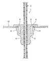
金型21によって成形されたクリップ付ワイヤハーネス1は、例えば、バックドアと車室内とに跨って配索される際には、図5に示すように、電線3と本体部5とが前記バックドアのインナーパネル12の取付孔13内に侵入すると、一対の係止片6のそれぞれの自由端が互いに近接する方向に弾性変形される。このとき、一対の係止片6のそれぞれの自由端が前記皿状部4の凹部8に収容される。
次いで、一対の係止片6が前記取付孔13を挿通すると、前記係止片6のそれぞれの自由端が弾性回復力によって、互いに離間する方向に変位される。そして、図6に示すように、皿状部4の周縁部が前記インナーパネル12に当接し、一対の係止片6のそれぞれの自由端が前記取付孔13の内周面に係止されると共に、前記係止片6のそれぞれの自由端が前記取付孔13の周縁部に係止される。
このため、上述のクリップ付ワイヤハーネス1は、前記皿状部4が前記パネル12に当接した状態において、前記係止片6のそれぞれの自由端が前記取付孔13の周縁部に係止すると共に、前記それぞれの自由端が前記取付孔13の内周面に係止するため、前記電線3の長手方向に対して前記クリップ2のガタツキが防止され、かつ、クリップ2と前記取付孔13とが確実に係止される。
上述の一実施形態にかかるクリップ付ワイヤハーネス1は、パネル12の取付孔13に係止されるクリップ2が電線3に一体成形されている。前記クリップ2は、前記取付孔13に重ねられると共に前記パネル12に当接される皿状部4と、前記皿状部4から立設され前記取付孔13に挿通される本体部5と、前記取付孔13の周縁部に係止される係止片6と、を備え、前記電線3が、前記皿状部4と前記本体部5とを貫通して設けられている。さらに、前記皿状部4には、前記係止片6の自由端が収容される凹部8が設けられている。
このため、本発明にかかるクリップ付ワイヤハーネス1は、パネル12の取付孔13にクリップ2を挿通させるだけで、前記クリップ付ワイヤハーネス1が前記取付孔13に係止される。このため、クリップ付ワイヤハーネス1は、従来のグロメットを有するワイヤハーネスよりも容易かつ迅速に、パネル12の取付孔13に取り付けることができる。
また、クリップ付ワイヤハーネス1は、前記皿状部4と前記パネル12とが当接した状態において、前記係止片6の自由端が前記皿状部4に接触することなく、前記取付孔13内に深く侵入できるため、前記係止片6の前記自由端が前記取付孔13の周縁部と内周面とに係止する。従って、クリップ付ワイヤハーネス1は、前記クリップ2が前記電線3の長手方向にガタつくことが防止され、かつ、前記クリップ2が前記取付孔13に確実に係止される。
また、クリップ付ワイヤハーネス1は、電線3にクリップ2が一体成形されて形成されているため、前記クリップ2の組立工程、前記クリップ2を前記電線3に組み付ける工程などが省略される。このため、クリップ付ワイヤハーネス1の製造工程が短縮され、製造にかかる所要時間が短縮される。
また、クリップ付ワイヤハーネス1は、止水機能が不要なバックドアのインナーパネル12等に好適に使用することができる。
なお、前述した実施形態は本発明の代表的な形態を示したに過ぎず、本発明は、実施形態および変形例に限定されるものではない。即ち、本発明の骨子を逸脱しない範囲で種々変形して実施することができる。
本発明にかかるクリップ付ワイヤハーネスは、自動車等の車体を構成するパネルに配索されるワイヤハーネスとして利用することができる。
1 クリップ付ワイヤハーネス
2 クリップ
3 電線
4 皿状部
5 本体部
6 係止片
8 凹部
9 覆い部
12 パネル
13 取付孔
2 クリップ
3 電線
4 皿状部
5 本体部
6 係止片
8 凹部
9 覆い部
12 パネル
13 取付孔
Claims (2)
- パネルの取付孔に係止されるクリップが電線に一体成形されたクリップ付ワイヤハーネスであって、
前記クリップは、前記取付孔に重ねられると共に前記パネルに当接される皿状部と、前記皿状部から立設され前記取付孔に挿通される本体部と、前記取付孔の周縁部に係止される係止片と、を備え、
前記電線が、前記皿状部と前記本体部とを貫通して設けられていることを特徴とするクリップ付ワイヤハーネス。 - 前記皿状部には、前記パネルに対向する面に凹部が設けられていることを特徴とする請求項1に記載のクリップ付ワイヤハーネス。
Priority Applications (1)
| Application Number | Priority Date | Filing Date | Title |
|---|---|---|---|
| CN201280031189.XA CN103782462A (zh) | 2011-06-24 | 2012-06-22 | 具有夹子的线束 |
Applications Claiming Priority (2)
| Application Number | Priority Date | Filing Date | Title |
|---|---|---|---|
| JP2011-140163 | 2011-06-24 | ||
| JP2011140163A JP2013009503A (ja) | 2011-06-24 | 2011-06-24 | クリップ付ワイヤハーネス |
Publications (1)
| Publication Number | Publication Date |
|---|---|
| WO2012176872A1 true WO2012176872A1 (ja) | 2012-12-27 |
Family
ID=47422700
Family Applications (1)
| Application Number | Title | Priority Date | Filing Date |
|---|---|---|---|
| PCT/JP2012/065977 Ceased WO2012176872A1 (ja) | 2011-06-24 | 2012-06-22 | クリップ付ワイヤハーネス |
Country Status (3)
| Country | Link |
|---|---|
| JP (1) | JP2013009503A (ja) |
| CN (1) | CN103782462A (ja) |
| WO (1) | WO2012176872A1 (ja) |
Cited By (2)
| Publication number | Priority date | Publication date | Assignee | Title |
|---|---|---|---|---|
| JP2013027268A (ja) * | 2011-07-26 | 2013-02-04 | Yazaki Corp | ワイヤハーネス |
| EP3572700A1 (de) * | 2018-05-24 | 2019-11-27 | Wagner Group GmbH | Wand- oder deckendurchführung für ein ansaugpartikelerkennungssystem |
Families Citing this family (3)
| Publication number | Priority date | Publication date | Assignee | Title |
|---|---|---|---|---|
| JP6389674B2 (ja) * | 2014-07-18 | 2018-09-12 | 矢崎総業株式会社 | クランプ及び該クランプを備えたワイヤハーネス |
| TWI640693B (zh) * | 2017-08-23 | 2018-11-11 | 圓展科技股份有限公司 | 理線裝置 |
| JP7480578B2 (ja) * | 2020-05-01 | 2024-05-10 | Toto株式会社 | 衛生陶器 |
Citations (2)
| Publication number | Priority date | Publication date | Assignee | Title |
|---|---|---|---|---|
| JPH07107641A (ja) * | 1993-10-04 | 1995-04-21 | Yazaki Corp | ワイヤーハーネス用プロテクタ |
| JP2002094258A (ja) * | 2000-09-14 | 2002-03-29 | Pfu Ltd | ケーブル固定構造 |
Family Cites Families (7)
| Publication number | Priority date | Publication date | Assignee | Title |
|---|---|---|---|---|
| JPS62128200A (ja) * | 1985-11-28 | 1987-06-10 | 株式会社 吉沢製作所 | コ−ド端末係止部の製造方法 |
| US5631445A (en) * | 1994-10-07 | 1997-05-20 | Ford Motor Company | Automotive fuel tank electrical fitting |
| JP4155731B2 (ja) * | 2001-10-16 | 2008-09-24 | 矢崎総業株式会社 | ワイヤハーネス用固定具 |
| JP2004234904A (ja) * | 2003-01-28 | 2004-08-19 | Kokusan Denki Co Ltd | グロメット付きワイヤハーネス |
| JP2005174858A (ja) * | 2003-12-15 | 2005-06-30 | Yazaki Corp | フラットワイヤーハーネス、グロメット及びこれらの製造方法 |
| JP4566863B2 (ja) * | 2005-08-31 | 2010-10-20 | 本田技研工業株式会社 | 車両用ケーブル保持装置 |
| JP2008105459A (ja) * | 2006-10-23 | 2008-05-08 | Sumitomo Wiring Syst Ltd | ワイヤハーネス用クランプ |
-
2011
- 2011-06-24 JP JP2011140163A patent/JP2013009503A/ja active Pending
-
2012
- 2012-06-22 CN CN201280031189.XA patent/CN103782462A/zh active Pending
- 2012-06-22 WO PCT/JP2012/065977 patent/WO2012176872A1/ja not_active Ceased
Patent Citations (2)
| Publication number | Priority date | Publication date | Assignee | Title |
|---|---|---|---|---|
| JPH07107641A (ja) * | 1993-10-04 | 1995-04-21 | Yazaki Corp | ワイヤーハーネス用プロテクタ |
| JP2002094258A (ja) * | 2000-09-14 | 2002-03-29 | Pfu Ltd | ケーブル固定構造 |
Cited By (5)
| Publication number | Priority date | Publication date | Assignee | Title |
|---|---|---|---|---|
| JP2013027268A (ja) * | 2011-07-26 | 2013-02-04 | Yazaki Corp | ワイヤハーネス |
| EP3572700A1 (de) * | 2018-05-24 | 2019-11-27 | Wagner Group GmbH | Wand- oder deckendurchführung für ein ansaugpartikelerkennungssystem |
| WO2019224203A1 (de) * | 2018-05-24 | 2019-11-28 | Wagner Group Gmbh | Ansaugpartikelerkennungssystem mit einer wand- oder deckendurchführung |
| CN112166277A (zh) * | 2018-05-24 | 2021-01-01 | 瓦格纳集团责任有限公司 | 具有壁穿引部或天花板穿引部的吸入颗粒物检测系统 |
| US11946836B2 (en) | 2018-05-24 | 2024-04-02 | Wagner Group Gmbh | Suction particle detection system having a wall or ceiling feedthrough |
Also Published As
| Publication number | Publication date |
|---|---|
| CN103782462A (zh) | 2014-05-07 |
| JP2013009503A (ja) | 2013-01-10 |
Similar Documents
| Publication | Publication Date | Title |
|---|---|---|
| JP5619471B2 (ja) | ワイヤハーネス用固定具 | |
| JP2013009503A (ja) | クリップ付ワイヤハーネス | |
| US20140251683A1 (en) | Wire harness with clip and wire harness having the same | |
| JP6128723B2 (ja) | ワイヤハーネス用固定具および当該ワイヤハーネス用固定具を備えたワイヤハーネス | |
| JP2011015467A (ja) | 電気接続箱 | |
| JP2012164520A (ja) | 中継コネクタ | |
| US20130228367A1 (en) | Electric wire fixing device | |
| JP5569115B2 (ja) | ワイヤハーネス | |
| JP2014060073A (ja) | コネクタ | |
| JP2013008541A (ja) | クリップ付ワイヤハーネス | |
| JP2016213053A (ja) | パッキン、コネクタ及びワイヤハーネス | |
| JP6580527B2 (ja) | ハーネスクランプ | |
| JP2013115856A (ja) | クリップ、クリップ付ワイヤハーネス | |
| JP5774932B2 (ja) | ワイヤハーネス | |
| JP2013113318A (ja) | クリップ、クリップ付ワイヤハーネス | |
| JP2011256903A (ja) | 溝付棒状部材用のクランプおよびワイヤーハーネス用プロテクタ | |
| JP5533192B2 (ja) | ワイヤハーネスを支持体に取り付ける方法 | |
| KR100924563B1 (ko) | 와이어 하네스용 프로텍터 | |
| JP5798755B2 (ja) | 外装部品付電線および該外装部品付電線を有するワイヤハーネス | |
| JP2012253886A (ja) | ワイヤハーネス | |
| JP2010126048A (ja) | ワイヤハーネス用固定具 | |
| JP5892578B2 (ja) | ワイヤハーネス | |
| KR101116882B1 (ko) | 와이어 이탈 방지용 지그 어셈블리 | |
| JP2017060283A (ja) | カバー部材、及び、電気接続箱 | |
| JP5755492B2 (ja) | プロテクタ |
Legal Events
| Date | Code | Title | Description |
|---|---|---|---|
| 121 | Ep: the epo has been informed by wipo that ep was designated in this application |
Ref document number: 12802101 Country of ref document: EP Kind code of ref document: A1 |
|
| NENP | Non-entry into the national phase |
Ref country code: DE |
|
| 122 | Ep: pct application non-entry in european phase |
Ref document number: 12802101 Country of ref document: EP Kind code of ref document: A1 |