WO2012176774A1 - 電動機 - Google Patents
電動機 Download PDFInfo
- Publication number
- WO2012176774A1 WO2012176774A1 PCT/JP2012/065635 JP2012065635W WO2012176774A1 WO 2012176774 A1 WO2012176774 A1 WO 2012176774A1 JP 2012065635 W JP2012065635 W JP 2012065635W WO 2012176774 A1 WO2012176774 A1 WO 2012176774A1
- Authority
- WO
- WIPO (PCT)
- Prior art keywords
- cooling medium
- shaft
- resolver
- passage
- rotation angle
- Prior art date
- Legal status (The legal status is an assumption and is not a legal conclusion. Google has not performed a legal analysis and makes no representation as to the accuracy of the status listed.)
- Ceased
Links
Images





Classifications
-
- H—ELECTRICITY
- H02—GENERATION; CONVERSION OR DISTRIBUTION OF ELECTRIC POWER
- H02K—DYNAMO-ELECTRIC MACHINES
- H02K11/00—Structural association of dynamo-electric machines with electric components or with devices for shielding, monitoring or protection
- H02K11/20—Structural association of dynamo-electric machines with electric components or with devices for shielding, monitoring or protection for measuring, monitoring, testing, protecting or switching
- H02K11/21—Devices for sensing speed or position, or actuated thereby
- H02K11/225—Detecting coils
-
- G—PHYSICS
- G01—MEASURING; TESTING
- G01D—MEASURING NOT SPECIALLY ADAPTED FOR A SPECIFIC VARIABLE; ARRANGEMENTS FOR MEASURING TWO OR MORE VARIABLES NOT COVERED IN A SINGLE OTHER SUBCLASS; TARIFF METERING APPARATUS; MEASURING OR TESTING NOT OTHERWISE PROVIDED FOR
- G01D5/00—Mechanical means for transferring the output of a sensing member; Means for converting the output of a sensing member to another variable where the form or nature of the sensing member does not constrain the means for converting; Transducers not specially adapted for a specific variable
- G01D5/12—Mechanical means for transferring the output of a sensing member; Means for converting the output of a sensing member to another variable where the form or nature of the sensing member does not constrain the means for converting; Transducers not specially adapted for a specific variable using electric or magnetic means
- G01D5/244—Mechanical means for transferring the output of a sensing member; Means for converting the output of a sensing member to another variable where the form or nature of the sensing member does not constrain the means for converting; Transducers not specially adapted for a specific variable using electric or magnetic means influencing characteristics of pulses or pulse trains; generating pulses or pulse trains
- G01D5/24428—Error prevention
- G01D5/24433—Error prevention by mechanical means
- G01D5/24442—Error prevention by mechanical means by mounting means
-
- H—ELECTRICITY
- H02—GENERATION; CONVERSION OR DISTRIBUTION OF ELECTRIC POWER
- H02K—DYNAMO-ELECTRIC MACHINES
- H02K1/00—Details of the magnetic circuit
- H02K1/06—Details of the magnetic circuit characterised by the shape, form or construction
- H02K1/22—Rotating parts of the magnetic circuit
- H02K1/32—Rotating parts of the magnetic circuit with channels or ducts for flow of cooling medium
-
- H—ELECTRICITY
- H02—GENERATION; CONVERSION OR DISTRIBUTION OF ELECTRIC POWER
- H02K—DYNAMO-ELECTRIC MACHINES
- H02K5/00—Casings; Enclosures; Supports
- H02K5/04—Casings or enclosures characterised by the shape, form or construction thereof
- H02K5/20—Casings or enclosures characterised by the shape, form or construction thereof with channels or ducts for flow of cooling medium
- H02K5/203—Casings or enclosures characterised by the shape, form or construction thereof with channels or ducts for flow of cooling medium specially adapted for liquids, e.g. cooling jackets
-
- H—ELECTRICITY
- H02—GENERATION; CONVERSION OR DISTRIBUTION OF ELECTRIC POWER
- H02K—DYNAMO-ELECTRIC MACHINES
- H02K5/00—Casings; Enclosures; Supports
- H02K5/04—Casings or enclosures characterised by the shape, form or construction thereof
- H02K5/22—Auxiliary parts of casings not covered by groups H02K5/06-H02K5/20, e.g. shaped to form connection boxes or terminal boxes
-
- H—ELECTRICITY
- H02—GENERATION; CONVERSION OR DISTRIBUTION OF ELECTRIC POWER
- H02K—DYNAMO-ELECTRIC MACHINES
- H02K9/00—Arrangements for cooling or ventilating
-
- H—ELECTRICITY
- H02—GENERATION; CONVERSION OR DISTRIBUTION OF ELECTRIC POWER
- H02K—DYNAMO-ELECTRIC MACHINES
- H02K9/00—Arrangements for cooling or ventilating
- H02K9/19—Arrangements for cooling or ventilating for machines with closed casing and closed-circuit cooling using a liquid cooling medium, e.g. oil
Definitions
- the present invention relates to an electric motor including a shaft rotation angle detection sensor in a housing.
- Patent Document 1 describes an electric motor in which a rotor and a stator are cooled by a cooling medium such as oil.
- the electric motor detects the rotation angle of the shaft to which the rotor is attached by a rotation angle detection sensor such as a resolver and uses it for control. Since the rotation angle detection sensor is generally mounted in the casing of the electric motor, it may take time to pull out the cable for extracting the output from the rotation angle detection sensor to the outside of the casing when assembling the motor. . Further, when the rotation angle detection sensor is fixed in the housing and the space where the rotation angle detection sensor is arranged is sealed, it is difficult to ensure the accuracy of the member if both functions are made compatible with one member. is there.
- the present invention provides a motor equipped with a rotation angle detection sensor inside a housing, which simplifies the work of pulling out a cable for taking out the output from the rotation angle detection sensor to the outside of the housing; It is an object of the present invention to realize at least one of suppressing accuracy required for a member used for sealing a space where a fixing and rotation angle detection sensor is arranged.
- the present invention includes a shaft to which a rotor is attached and an internal cooling medium passage through which a cooling medium passes, a housing in which the shaft is disposed and rotatably supported, and one end of the shaft A cooling medium supply part that is provided inside the housing on the part side and supplies the cooling medium to the internal cooling medium passage; and a rotation angle of the shaft attached to the one end side of the shaft A rotation angle detection sensor for detecting the cooling medium and a through-hole through which the cooling medium supplied from the cooling medium supply unit passes, and between the cooling medium supply unit and the one end of the shaft A holding member that guides the cooling medium to the cooling medium passage and presses the rotation angle detection sensor from the one end side of the shaft; Holds the one end portion and electrically connected to the terminal of the signal cable for taking out the output of the rotation angle detecting sensor, a motor, characterized in that it comprises a connector attached to the housing.
- the casing in which the cooling medium supply unit is provided has a recess into which the pressing member is fitted.
- the pressing member is fitted in the recess and has a space between the end surface opposite to the side pressing the rotation angle detection sensor and the recess.
- the pressing member is preferably fixed to the casing by a plate-like member.
- the terminal held by the connector is pulled out in a direction orthogonal to the rotation center axis of the shaft.
- the present invention is an electric motor that rotationally drives an upper swing body of a construction machine, and has a rotor mounted therein, a shaft having an internal cooling medium passage through which a cooling medium passes, and the shaft disposed therein.
- a casing that is rotatably supported, and a cooling medium supply section that is provided inside the casing on one end side of the shaft and is disposed above and supplies the cooling medium to the internal cooling medium passage
- a rotation angle detection sensor that is attached to the one end side of the shaft and detects the rotation angle of the shaft, and a through-hole through which the cooling medium supplied from the cooling medium supply unit passes. And is interposed between the cooling medium supply section and the one end of the shaft to guide the cooling medium to the cooling medium passage and to detect the rotation angle detection unit.
- a pressing member that presses the shaft from the one end side of the shaft, a plate-shaped fixing member that fixes the pressing member to the housing, and one end of a signal cable for taking out the output of the rotation angle detection sensor
- a housing that holds a terminal that is electrically connected to the housing, is attached to the housing, and that pulls out the terminal in a direction perpendicular to the rotation center axis of the shaft; and the cooling medium supply section And a seal member provided between the recess and the pressing member and between the pressing member and the shaft. It is an electric motor.
- the present invention provides a motor equipped with a rotation angle detection sensor inside a housing, which simplifies the work of pulling out a cable for taking out the output from the rotation angle detection sensor to the outside of the housing; It is possible to realize at least one of suppressing accuracy required for a member used for sealing a space in which the fixing and rotation angle detection sensors are arranged.
- FIG. 1 is a plan view showing a hybrid hydraulic excavator using the electric motor according to this embodiment as an electric motor for turning.
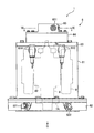
- FIG. 2 is a front view showing the electric motor according to the present embodiment.
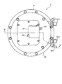
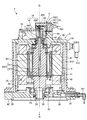
- FIG. 3 is a plan view of the electric motor according to the present embodiment. 4 is a VV arrow view of FIG.
- FIG. 5 is a view taken along arrow VI-VI in FIG.
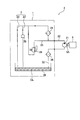
- FIG. 6 is a schematic diagram showing a cooling structure of the electric motor according to the present embodiment.
- FIG. 7 is an enlarged cross-sectional view showing the holding structure of the rotation angle detection sensor according to the present embodiment.
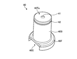
- FIG. 8 is a perspective view of the resolver presser.
- FIG. 9 is a perspective view of the resolver presser.
- FIG. 8 is a perspective view of the resolver presser.
- FIG. 10 is a plan view showing the inside of the convex portion of the housing of the electric motor according to the present embodiment.
- FIG. 11 is a diagram showing a structure for fixing the resolver presser to the concave portion (rotation angle detection sensor holding portion).
- FIG. 12 is a diagram illustrating another example when the connector is attached to the flange convex portion.
- FIG. 13 is an enlarged cross-sectional view showing a holding structure of a rotation angle detection sensor according to a modification of the present embodiment.
- FIG. 1 is a plan view showing a hybrid hydraulic excavator using the electric motor according to this embodiment as an electric motor for turning.
- the hybrid excavator 10 includes a pair of left and right crawler belts 11 forming a lower traveling body, an upper swing body 12, a swing circle 13 connecting the lower traveling body and the upper swing body 12, and an electric motor 1 functioning as a swing motor,
- the swing pinion 1 ⁇ / b> A includes a boom 14, an arm 15, and a bucket 16, and a work machine 17 attached to the upper swing body 12.
- the pair of left and right crawler belts 11 are driven by a right traveling hydraulic motor and a left traveling hydraulic motor to cause the hybrid excavator 10 to travel.
- the upper turning body 12 is turned by the electric motor 1 that functions as a turning motor.
- An outer race of a swing circle 13 is fixed to the upper swing body 12, and an inner race of the swing circle 13 is fixed to the lower traveling body. With such a structure, the swing circle 13 connects the upper swing body 12 and the lower traveling body.
- the electric motor 1 is installed vertically, that is, when the hybrid excavator 10 is installed on a horizontal plane, the input / output shaft of the electric motor 1 is directed in the direction in which gravity acts.
- the input / output shaft of the electric motor 1 is connected to the swing pinion 1A through a swing machinery having a speed reduction mechanism.
- the swing pinion 1 ⁇ / b> A meshes with internal teeth attached to the inner race of the swing circle 13.
- the driving force of the electric motor 1 is transmitted to the swing pinion 1A through the swing machinery and turns the upper swing body 12.
- the boom 14, the arm 15 and the bucket 16 are driven by hydraulic cylinders for the boom 14, the arm 15 and the bucket 16 through hydraulic control oil fed from a hydraulic pump (not shown), respectively, for excavation and the like. Perform work.
- the hybrid excavator 10 drives the generator and the hydraulic pump with the internal combustion engine, and drives the electric motor 1 through an inverter (not shown) with the electric power of the generator to turn the upper swing body 12. Further, the hybrid excavator 10 uses the electric motor 1 as a generator to generate a braking force necessary for stopping the upper swing body 12, and the electric power generated by the electric motor 1 by the braking force Store in power storage devices such as secondary batteries. Thus, the hybrid excavator 10 is a so-called hybrid construction vehicle. In this embodiment, although the example which used the electric motor 1 as a turning motor of the hybrid hydraulic shovel 10 which is a kind of construction vehicle is demonstrated, the application object of the electric motor 1 is not limited to this. Hybrid hydraulic excavator 10 may be of a system that does not have an internal combustion engine, that is, a system that is driven by electric power of a power storage device. Next, the structure of the electric motor 1 will be described.
- FIG. 2 is a front view showing the electric motor according to the present embodiment.
- FIG. 3 is a plan view of the electric motor according to the present embodiment.
- 4 is a VV arrow view of FIG.
- FIG. 5 is a view taken along arrow VI-VI in FIG.
- the electric motor 1 is arranged inside a cylindrical housing 6 as a shaft 8 as an input / output shaft, a rotor core 82 attached to the shaft 8, and an outer peripheral portion of the rotor core 82.
- the shaft 8 has bearings 7A and 7B attached to both sides thereof, and is rotatably supported by the housing 6 via the bearings 7A and 7B.
- the casing 6 includes a casing barrel 61 that is a cylindrical member, and a first flange 62 as an end portion side member that is attached to one end portion (end portion on the input / output side of the shaft 8) of the casing barrel 61. And a disc-shaped second flange 63 attached to the other end of the casing body 61.
- the second flange 63 includes a flange convex portion 64 and a lid 65, but the flange convex portion 64 and the lid 65 are also part of the housing 6.
- a space surrounded by the casing body 61, the first flange 62, and the second flange 63 is the inside of the casing 6.
- the first flange 62 is disposed on the lower side (the direction side on which gravity acts, and the direction side indicated by the arrow G in FIGS. 2 and 5).
- the state where the hybrid excavator 10 is in contact with the horizontal plane is the state in which the electric motor 1 is used, and the lower position in that state.
- the 1st flange 62 is arrange
- the housing body 61 is a member whose inner peripheral surface is cylindrical.
- the case body 61 includes a cooling water inlet 613 for introducing water for cooling the electric motor 1 into the water jacket 612 and a cooling water outlet 614 for discharging the cooling water from the water jacket.
- a liquid other than water, such as oil may be introduced into the water jacket 612 to cool the electric motor 1.
- the first flange 62 is a disk-shaped member.
- the first first flange 62 has a cooling medium discharge port 621 for discharging the cooling medium from the inside of the housing 6 during operation of the electric motor 1 and leading it to a pump that sucks and discharges the cooling medium. Yes.
- the first flange 62 has a drain port 622 for extracting the cooling medium in the housing 6 when the electric motor 1 is maintained and inspected.
- the first flange 62 is disposed at one end of the housing 6 and the shaft 8 passes therethrough.
- a power transmission joint or a reduction gear input shaft or the like is attached to the shaft 8 penetrating from the first flange 62.
- the first flange 62 is a separate member from the case body 61, but the first flange 62 and the case body 61 may be the same member.
- the second flange 63 is arranged on the upper side, that is, on the side opposite to the direction in which the gravity acts in the state where the electric motor 1 is used.
- the second flange 63 has a flange convex portion 64 and a lid 65.
- the lid 65 has a cooling medium inlet 651.
- the cooling medium inlet 651 is for introducing the cooling medium discharged from the pump into the housing 6.
- the bearing 7 ⁇ / b> A attached to one end of the shaft 8 is attached to the first flange 62, and the bearing 7 ⁇ / b> B attached to the other end of the shaft 8 is attached to the second flange 63.
- the shaft 8 can be rotated to the housing 6 (more specifically, the housing body 61, the first flange 62, and the second flange 63) by two bearings 7A and 7B provided on both sides. And rotates about the rotation center axis Zr.
- the rotation center axis Zr is the center axis of the shaft 8.
- the rotor core 82 attached to the outer periphery of the shaft 8 is a structure in which a plurality of steel plates (electromagnetic steel plates) are laminated.
- the rotor core 82 is sandwiched between balance plates 83 and 84 from both sides in the direction in which the steel plates are laminated (lamination direction).
- the balance plates 83 and 84 are attached to the shaft 8 so as to prevent the plurality of steel plates constituting the rotor core 82 from being separated, and apply compressive force to the plurality of steel plates.
- the balance plate 84 on the first flange 62 side is disposed on the first flange 62 side, that is, on the input / output side of the shaft 8 of the electric motor 1.
- the stator 9 attached to the inner peripheral portion of the casing body 61 of the casing 6 is disposed on the outer peripheral portion of the rotor core 82.
- the stator 9 is a structure in which a coil 92 is wound around a stator core 91. A portion protruding from the stator core 91 of the coil 92 is a coil end.
- the stator core 91 is a structure in which a plurality of steel plates (magnetic steel plates) are stacked.
- the shaft 8 includes an axial passage 811 extending along the rotation center axis Zr, and a plurality of radial passages extending from the axial passage 811 toward the radially outer side of the shaft 8 and opening on the surface of the shaft 8. 812.
- the axial passage 811 and the radial passage 812 serve as an in-shaft cooling medium passage 813 as an internal cooling medium passage.
- the balance plate 84 has a recess 841 on the side in contact with the rotor core 82.
- the rotor core 82 has a rotor core through-hole 821 that passes through the rotor core 82 in the stacking direction of the plurality of steel plates, that is, in the direction parallel to the rotation center axis Zr of the shaft 8.
- the rotor core 82 has a plurality of permanent magnets (not shown).
- the balance plate 83 on the second flange 63 side has a balance plate through hole 831 that extends in a direction parallel to the rotation center axis Zr of the shaft 8.
- the in-shaft cooling medium passage 813, the recess 841, the rotor core through-hole 821 and the balance plate through-hole 831 communicate with each other to form a passage through which the cooling medium passes.
- These are provided in the shaft 8 and the rotor core 82 which are the rotating bodies, and serve as a rotating body side cooling medium passage for allowing the cooling medium to pass therethrough.
- a resolver 50 as a rotation angle detection sensor for detecting the rotation angle of the shaft 8 is attached to one end portion side of the shaft 8, more specifically, to a side peripheral portion on the end portion side on the second flange 63 side. .
- An axial passage 811 is opened at the end on the second flange 63 side. That is, the resolver 50 is attached to the side peripheral portion of the shaft 8 and to the end side where the axial passage 811 is open.
- the flange convex portion 64 of the second flange 63 has a convex portion internal space 641.
- a resolver presser 40 as a presser member is provided in the convex inner space 641.
- the resolver presser 40 has a function for supplying a cooling medium from the cooling medium supply unit 3 of the lid 65 which is a stationary system to the shaft 8 which is a rotating system, and a resolver 50 as a rotation angle detection sensor to the second flange 63. And a function of pressing and fixing the flange convex portion 64 provided.
- the resolver retainer 40 has a cooling medium introduction passage 41 that penetrates the inside thereof.
- the cooling medium introduction passage 41 faces the opening of the axial passage 811 of the shaft 8 and introduces the cooling medium into the axial passage 811.
- the flange convex part 64 has the bearing side channel
- the bearing 7 ⁇ / b> B is supplied with a cooling medium from the bearing-side passage 643.
- the flange convex portion 64 is attached with a connector 55 that holds a cable for taking out the output of the resolver 50.
- the lid 65 is attached to the opening of the flange convex portion 64 and closes the convex internal space 641 of the flange convex portion 64.
- the lid 65 has a cooling medium supply unit 3. More specifically, the cooling medium supply unit 3 is provided inside a lid 65 constituting the housing 6. Since the lid 65 is disposed on the upper side (opposite to the vertical direction), the cooling medium supply unit 3 is also disposed on the upper side.
- the cooling medium supply unit 3 includes a bearing passage 23 and a rotor passage 28 which will be described later.
- the cooling medium supply unit 3 introduces the cooling medium from a cooling medium inlet 651 attached to the lid 65 which is a stationary system, and the cooling medium is supplied to the in-shaft cooling medium passage 813 of the shaft 8 which is the rotating system.
- the cooling medium supply unit 3 supplies the cooling medium from the stationary system to the rotating system.
- the cooling medium supply unit 3 also supplies the cooling medium introduced from the cooling medium inlet 651 to the bearing side passage 643 of the flange convex portion 64 via the bearing passage 23.
- the cooling medium supplied to the bearing side passage 643 is supplied to the bearing 7B.
- the lid 65 attached to the flange convex portion 64 includes a first cooling medium distribution passage 653 that distributes the cooling medium from the cooling medium inlet 651, a second cooling medium distribution passage 655, and a third cooling medium.
- a medium distribution passage 656 and a fourth cooling medium distribution passage 657 are provided.
- the lid 65 includes a filter storage portion 654 that stores the filter 24, a relief passage 25, and a relief valve 26.
- the cooling medium inlet 651 is connected to the filter storage unit 654 via the first cooling medium distribution passage 653.
- the second cooling medium distribution passage 655 is connected to the filter storage unit 654 and introduces a part of the cooling medium that has passed through the filter 24 into the cooling medium introduction passage 41 of the resolver holder 40.
- the second cooling medium distribution passage 655 and the cooling medium introduction passage 41 correspond to the rotor passage 28.
- the third cooling medium distribution passage 656 is connected to the filter storage unit 654, and introduces the remainder of the cooling medium that has passed through the filter 24 and introduced into the cooling medium introduction passage 41 into the fourth cooling medium distribution passage 657.
- the third cooling medium distribution passage 656, the fourth cooling medium distribution passage 657, and the bearing side passage 643 correspond to the bearing passage 23.
- the relief passage 25 connects the cooling medium inlet 651 and the relief valve 26.
- the relief valve 26 is interposed between the relief passage 25 and the second cooling medium distribution passage 655 and the third cooling medium distribution passage 656 so as to bypass the filter 24.
- the relief valve 26 is opened, and the cooling medium from the cooling medium inlet 651 is bypassed through the filter 24 to the second cooling medium distribution passage 655 and It flows to the third cooling medium distribution passage 656.
- the valve opening pressure of the relief valve 26 can be set, for example, to the pressure in the relief passage 25 when the filter 24 is clogged and needs to be replaced.
- the cooling medium can be reliably supplied to the bearing 7B, the rotor core 82, and the like. Further, when the valve opening pressure of the relief valve 26 is set as described above and a means for notifying that the relief valve 26 is opened is prepared, the replacement timing of the filter 24 can be determined by opening the relief valve 26. Can be notified.
- the passages orthogonal to the rotation center axis Zr of the electric motor 1 are arranged in the same plane.
- the central axes of the respective passages are arranged in the same plane.
- the medium distribution passage 653 and the passage connecting the cooling medium inlet 651 and the filter storage portion 654 have their central axes arranged in the same plane.
- the passage in the lid 65 orthogonal to the rotation center axis Zr of the electric motor 1 is formed by, for example, being drilled in the lid 65 from the horizontal direction.
- the passage in the lid 65 is formed.
- the supply of the cooling medium is not affected by the rotation of the rotor core 82. For this reason, the fluctuation
- a cooling structure provided in the electric motor 1 will be described.
- FIG. 6 is a schematic diagram showing a cooling structure of the electric motor according to the present embodiment.
- the shaft 8 and the stator 9 are cooled by the cooling medium CL, and the bearing 7B is lubricated by the cooling medium CL.
- the cooling structure 2 of the electric motor 1 includes a pump 21, a pump electric motor 5, a passage 22, a bearing passage 23, a rotor passage 28, an oil reservoir 39, a discharge passage 32, a filter 24, a relief, A passage 25, a relief valve 26, and a filter 38 are included.
- a cooler that cools the cooling medium CL may be provided between the filter 38 and the pump 21.
- the pump 21 and the pump motor 5 are connected by an input / output shaft 5 ⁇ / b> A of the pump motor 5.
- the drive means of the pump 21 may be other than the pump electric motor 5, and may be, for example, an internal combustion engine that is a power generation source of the hybrid excavator 10 shown in FIG.
- the filter 24 and the filter 38 are built in the electric motor 1.
- the pump motor 5 drives the pump 21. Then, the pump 21 sucks the cooling medium CL from the discharge passage 32 and discharges it to the passage 22. In the process of passing through the filter 24, the cooling medium CL is removed of foreign matters and the like, and flows into the bearing passage 23 and the rotor passage 28.
- the cooling medium CL that has flowed into the bearing passage 23 is collected in the oil reservoir 39 after the bearing 7B is cooled and lubricated.
- the cooling medium CL that has flowed into the rotor passage 28 is collected in the oil reservoir 39 after cooling the rotor core and coil of the electric motor 1.
- the oil reservoir 39 and the suction port of the pump 21 are connected by a discharge passage 32 provided with a filter 38 in the middle. After the cooling medium CL collected in the oil reservoir 39 passes through the discharge passage 32, foreign matter is removed by the filter 38, and is again sucked into the pump 21 and discharged to the passage 22.
- the passage 22 is connected to the discharge port of the pump 21 and branches into the inlet side of the filter 24 and the relief passage 25 in the electric motor 1.
- the passage through which the cooling medium provided on the outlet side of the filter 24 passes branches into a bearing passage 23 and a rotor passage 28.
- the bearing passage 23 supplies a cooling medium to the bearing 7B to cool and lubricate it.
- the rotor passage 28 supplies a cooling medium to the rotor of the electric motor 1 and cools it.
- the cooling structure 2 does not necessarily have the bearing passage 23.
- a relief passage 25 branched from the passage 22 connected to the discharge port of the pump 21 is connected to the inlet of the relief valve 26.
- the outlet side of the relief valve 26 is connected to the outlet side of the filter 24.
- the pressure in the passage 22 and the relief passage 25 increases.
- the relief valve 26 opens.
- the relief valve 26 bypasses the filter 24 and causes the cooling medium to flow through the bearing passage 23 and the rotor passage 28.
- the relief valve 26 causes the cooling medium to flow through the bearing passage 23 and the rotor passage 28 to cool and lubricate the bearing 7B, the rotor core, etc. Can maintain the cooling.
- the flow of the cooling medium when the electric motor 1 is cooled will be described.
- the cooling medium flowing out from the balance plate through hole 831 is supplied to the coil end of the stator 9 (the portion where the coil 92 protrudes from the stator core 91) by centrifugal force.
- This cooling medium cools the stator 9 in the process of flowing downward in the housing 6 and is collected in the first discharge port 27 provided on the inner side of the housing 6 of the first flange 62.
- the symbol OL in FIG. 4 indicates the liquid level of the cooling medium that accumulates in the oil reservoir 39.
- the amount of the cooling medium accumulated in the oil reservoir 39 is such that the part of the coil end protruding toward the first flange is always immersed so that the cooling medium discharge port 621 can be immersed.
- the coil end is adjusted to cool the coil end.
- the cooling medium that has not flowed into the rotor passage 28 flows into the bearing passage 23 and is supplied to the bearing 7B.
- the cooling medium flows downward in the housing 6 after cooling and lubricating the bearing 7B.
- the rotor core 82 and a permanent magnet (not shown) are contacted and cooled.
- a part of the cooling medium in contact with the rotor core 82 is supplied to the stator 9 radially outside the rotor core 82 by the centrifugal force to cool it.
- the cooling medium that has cooled the stator 9 flows downward in the housing 6 and is collected in an oil reservoir 39 provided on the inner side of the housing 6 of the first flange 62.
- the cooling medium collected in the oil reservoir 39 mainly flows into the discharge passage 32 through the first discharge port 27, and then is guided to the filter 38 to remove foreign matters and the like, and then the first flange 62 is removed. It is discharged from the cooling medium discharge port 621 it has.
- the coolant in the oil reservoir 39 that has not passed through the first outlet 27 flows into the bearing outer space 29 through the space between the inner ring, outer ring, and rolling element of the bearing 7A, and then the second exhaust. Pass through exit 30.
- the cooling medium collected in the oil reservoir 39 cools and lubricates the bearing 7A.
- the cooling medium that has passed through the second discharge port 30 flows into the discharge passage 32 and is then guided to the filter 38 to remove foreign matters and the like, and then discharged from the cooling medium discharge port 621 of the first flange 62. .
- the cooling medium cools the rotor core 82 and the stator 9 and cools and lubricates the bearings 7A and 7B.
- the cooling water is supplied from the cooling water inlet 613 to the water jacket 612 included in the casing body 61 of the casing 6.
- This cooling water mainly cools the stator 9 via the housing 6.
- a gasket 35 is provided as a sealing member for sealing the water jacket 612.
- the gasket 35 prevents the cooling medium inside the housing 6 from flowing out between the housing body 61 and the first flange 62 and entering the water jacket 612 or out of the housing 6. It also has a function as an oil seal.
- a holding structure for the rotation angle detection sensor provided between the lid 65 of the housing 6 of the electric motor 1 and the flange protrusion 64 will be described.
- FIG. 7 is an enlarged cross-sectional view showing the holding structure of the rotation angle detection sensor according to the present embodiment.
- 8 and 9 are perspective views of the resolver presser.
- FIG. 10 is a plan view showing the inside of the convex portion of the housing of the electric motor according to the present embodiment.
- FIG. 11 is a diagram showing a structure for fixing the resolver presser to the concave portion (rotation angle detection sensor holding portion).
- FIG. 12 is a diagram illustrating another example when the connector is attached to the flange convex portion.
- the resolver 50 includes a resolver rotor 50R attached to the shaft 8 that is a rotating system, and a resolver stator 50S attached to a second flange 63 that is a stationary system.
- the resolver rotor 50 ⁇ / b> R rotates with the shaft 8. Therefore, the resolver rotor 50 ⁇ / b> R rotates around the rotation center axis Zr of the shaft 8.
- the resolver stator 50 ⁇ / b> S of the resolver 50 is fitted into a rotation angle detection sensor holding part 642 that is a recess provided in the second flange 63.
- the shaft 8 to which the resolver rotor 50R is attached has a step portion 8D having an outer diameter larger than the inner diameter of the resolver rotor 50R, and the resolver rotor 50R is locked by the step portion 8D.
- the resolver rotor 50R is disposed at a position facing the resolver stator 50S.
- the resolver 50 is pressed against the second flange 63 from the one end of the shaft 8 (end surface 8Ta where the axial passage 811 opens) by the resolver presser 40.
- the resolver presser 40 is fixed to the second flange 63 by a fixing member 54 as a plate-like member.
- the resolver 50 (more specifically, the resolver stator 50 ⁇ / b> S) is fixed to the second flange 63.
- the fixing member 54 can be manufactured, for example, by punching and bending a metal plate material.
- the resolver presser 40 includes a cylindrical body portion 40B, and an overhang portion that is provided at one end portion of the body portion 40B and projects outward in the radial direction of the body portion 40B. 40F.
- drum 40B has the groove
- the groove 42 is provided with an O-ring 53 as a seal member.
- the resolver retainer 40 is made of, for example, an aluminum alloy. Since the resolver retainer 40 is a separate member from the lid 65, it can also be manufactured from a material different from the material of the lid 65. By doing in this way, while being able to use an appropriate material for the resolver presser 40, the precision of the resolver presser 40 can also be improved.
- the end face on one end side of the resolver presser 40 that is, the end face 40 Tb on the protruding part 40 F side, is in contact with the resolver stator 50 S of the resolver 50.
- the end surface on the other end side of the resolver presser 40 that is, the end surface 40Ta on the groove 42 side, is fitted into the recess 65U included in the lid 65 and faces the recess 65U.
- the lid 65 is a portion of the housing 6 where the cooling medium supply unit 3 shown in FIG. 4 is provided.
- the cooling medium introduction passage 41 penetrates from the end surface 40Ta of the body portion 40B toward the overhang portion 40F.
- the resolver presser 40F has a recess 43 on the overhanging portion 40F side.
- the recess 43 has a circular shape in plan view, and has the smallest inner diameter on the end face 40Ta side on the groove 42 side and the inner diameter on the end face 40Tb side of the overhanging portion 40F.
- a portion where the inner diameter of the concave portion 43 changes is a stepped portion 40D.
- the portion where the shaft 8 protrudes from the resolver rotor 50 ⁇ / b> R of the resolver 50 is inserted into the recess 43.
- An oil seal 51 as a seal member is provided between the shaft 8 and the recess 43 of the resolver presser 40. The oil seal 51 provided in the recess 43 is locked to the stepped portion 40D.
- the overhanging portion 40F of the resolver presser 40 has a cutout portion 40C in which a part of a circle is cut off by one string when viewed from a direction parallel to the penetration direction of the cooling medium introduction passage 41.
- the notch 40 ⁇ / b> C provided in the overhanging portion 40 ⁇ / b> F is engaged with the detent portion 54 ⁇ / b> T of the fixing member 54 folded toward the rotation angle detection sensor holding portion 642.
- the rotation of the resolver retainer 40 around the rotation center axis Zr is suppressed.
- 11 shows a state in which the resolver presser 40, the fixing member 54, and the rotation angle detection sensor holding unit 642 are viewed from the notch 40C of the resolver presser 40.
- the flange convex portion 64 is a portion protruding from the second flange 62, and has a convex inner space 641 therein.
- the convex portion inner space 641 is a space surrounded by four walls 643A, 643B, 643C, and 643D protruding from the second flange 62 shown in FIG. It is done.
- the lid 65 is in contact with the end surfaces of the four walls 643A, 643B, 643C, and 643D, that is, the end surface (convex portion end surface) 64T of the flange convex portion 64 on the opening side of the convex portion internal space 641. As shown in FIGS.
- the convex end surface 64T has grooves 64S extending toward the entire circumference of the four walls 643A, 643B, 643C, and 643D so as to surround the opening of the convex internal space 641.
- an O-ring 52 as a seal member is attached to the groove 64S.
- the O-ring 52 seals the convex inner space 641.
- the resolver presser 40 is disposed in the convex inner space 641 and between the lid 65 and the second flange 62, more specifically, the concave portion 65U of the lid 65 and the rotation angle detection sensor holding portion 642 of the flange convex portion 64. It intervenes between.
- the resolver presser 40 is attached to the rotation angle detection sensor holding part 642 and presses the resolver 50 and is fixed to the second flange 63, the end face on the other end side, that is, the end face 40Ta on the groove 42 side, is a flange convex part. It protrudes outside the convex portion inner space 641 from the 64 convex portion end face 64T.
- the protruding resolver presser 40 is fitted into the recess 65U of the lid 65.
- the depth of the concave portion 65U is larger than the dimension from the convex portion end surface 64T to the end surface 40Ta on the groove 42 side. For this reason, a space BS is formed between the end face 40Ta on the groove 42 side of the resolver presser 40 fitted in the recess 65U and the portion of the recess 65U facing this.
- the space BS avoids contact between the resolver 50 and the lid 65, for example, when the resolver presser 40 extends due to temperature rise.
- the fixing member 54 passes through the first opening 54Ha of the fixing member 54 through the resolver presser 40 (more specifically, the body 40B of the resolver presser 40). Is fixed to the second flange 63 shown in FIG. By doing so, the resolver 50 (more specifically, the resolver stator 50S) is fixed to the second flange 63 via the resolver presser 40 and the fixing member 54.
- the lid 65 is attached to the flange convex portion 64, the end face 40Ta of the resolver retainer 40 is fitted into the recess 65U of the lid 65. However, since the space BS is interposed between the recess 65U and the resolver retainer 40, the lid 65 From this, it is avoided that force is applied to the resolver 50 via the resolver presser 40.
- the resolver holding structure 4 fixes and holds the resolver 50 to the second flange 63 using the resolver presser 40 and the fixing member 54 without using the lid 65. That is, the resolver holding structure 4 separates the function of holding the resolver 50 from the lid 65 (resolver holding function), and the resolver holding function and the fixing member 54 have the resolver holding function.
- the lid 65 has a function of sealing the convex inner space 641 (a convex space sealing function).
- a second cooling medium distribution passage 655 that is a part of the cooling medium supply unit 3 (see FIG. 4) is opened.
- the opening of the second cooling medium distribution passage 655 is opposed to the opening on the end surface 40Ta side of the cooling medium introduction passage 41 of the resolver presser 40 fitted in the recess 65U.
- the opening of the cooling medium introduction passage 41 on the overhanging portion 40F side faces the opening of the axial passage 811 on the end surface 8Ta side of the shaft 8. Since the O-ring 53 is interposed between the recess 65U of the lid 65 and the resolver presser 40, the leakage of the cooling medium from between the two is suppressed. Further, since the oil seal 51 is interposed between the resolver presser 40 and the shaft 8, leakage of the cooling medium from between them is suppressed.
- the resolver holding structure 4 supplies the cooling medium supplied from the second cooling medium distribution passage 655 to the axial passage 811 of the shaft 8 via the cooling medium introduction passage 41 of the resolver retainer 4. Can do. Since the resolver holder 40 is provided in a stationary system and the shaft 8 is provided in a rotating system, the resolver holding structure 4 can supply a cooling medium from the stationary system to the rotating system.
- the lid 65 having the cooling medium supply unit 3 (see FIG. 4) including the second cooling medium distribution passage 655 and the resolver presser 40 having the cooling medium introduction passage 41 are separate members.
- the lid 65 and the resolver holder 40 are disassembled, and the cooling medium supply unit 3 or The cooling medium introduction passage 41 can be easily cleaned.
- the cooling medium path can be disassembled into short units, so there is also an advantage that the cooling medium path can be easily maintained.
- the inner diameter of the second cooling medium distribution passage 655 is D1
- the inner diameter of the cooling medium introduction passage 41 is D2
- the same resolver presser 40 is used and only the inner diameter D2 of the cooling medium introduction passage 41 is perforated to adjust the supply amount of the cooling medium to the shaft 8. You can also In this way, the parts can be shared.
- the space BS formed between the recess 65U of the lid 65 and the resolver holder 40 has a function of storing and holding the cooling medium supplied from the second cooling medium distribution passage 655. For this reason, even if some trouble occurs in the cooling medium supply system and the supply of the cooling medium from the second cooling medium distribution passage 655 is temporarily interrupted, the cooling medium stored in the space BS is not stored in the shaft 8. Since it is supplied to the axial passage 811, the cooling of the rotor and the stator of the electric motor 1 can be continued.
- the opening of the second cooling medium distribution passage 655 and the opening of the cooling medium introduction passage 41 are opposed to each other, but they are offset (the overlap between the two is reduced or both are not overlapped).
- the cooling medium flowing out from the second cooling medium distribution passage 655 collides with the end surface 40Ta of the resolver retainer 40 and then flows into the cooling medium introduction passage 41. By doing in this way, since the time which the cooling medium which flowed out from the 2nd cooling medium distribution channel 655 stays in space BS can be lengthened, a cooling medium can be more efficiently stored in space BS.
- the resolver 50 has a plurality of terminals (resolver terminals) 50T.
- the plurality of resolver terminals 50T supply an excitation signal to the resolver 50 and take out the rotation angle of the shaft 8 detected by the resolver 50.
- the plurality of resolver terminals 50 ⁇ / b> T are electrically connected to terminals (connector terminals) 55 ⁇ / b> T that the connector 55 has and holds with the signal cable 56. That is, the signal cable 56 is for taking out the output of the resolver 50, and one end is electrically connected to the connector terminal 55T and the other end is electrically connected to the resolver terminal 50T.
- the signal cable 56 also has a function of supplying an excitation signal to the resolver 50.
- the connector 55 includes various sensors for detecting the state of the electric motor 1 such as a temperature sensor for detecting the temperature in the electric motor 1 and a sensor for detecting a contact state of a power cable that supplies power to the coil 92 of the stator 9.
- sensors for detecting the state of the electric motor 1 such as a temperature sensor for detecting the temperature in the electric motor 1 and a sensor for detecting a contact state of a power cable that supplies power to the coil 92 of the stator 9.
- a signal cable 56S from the sensor is also connected.
- the flange convex portion 64 has a connector mounting hole 64H for mounting the connector 55.
- a connector mounting hole 64H is provided in the wall 643A shown in FIG.
- the connector 55 is attached to the connector attachment hole 64H from the convex portion internal space 641 side of the flange convex portion 64 with the seal member 55S interposed therebetween.
- the connector 55 may be attached to the connector attachment hole 64H from outside the convex portion inner space 641 with the seal member 55S interposed therebetween. Since the flange convex portion 64 is a part of the housing 6, the connector 55 is attached to the housing 6.
- the connector 55 appearing from the connector mounting hole 64H is electrically connected to the connector terminal 55T of the connector 55 and is connected to an external connector connected to the control device of the electric motor 1. By doing so, the control device can output the resolver 50 and excite the resolver 50.
- the convex inner space 641 of the flange convex portion 64 has a size (convex space height) between the convex inner space bottom 64B (surface on the lid 65 side of the second flange 63) and the lid 65.
- the size is sufficient to attach the connector 55.
- a resolver unit is prepared in which the connector terminal 55T is electrically connected to one end of the signal cable 56, the resolver terminal 50T is electrically connected to the other end, and the connector terminal 55T is held by the connector 55. To do.
- the resolver 50 is attached and fixed to the flange protrusion 64, and the connector 55 is attached to the connector attachment hole 64H of the flange protrusion 64 with the seal member 55S interposed therebetween.
- the lid 65 is attached to the flange convex portion 64 to seal the convex portion inner space 641.
- the connector 55 is attached to the connector attachment hole 64H of the flange convex portion 64 with the seal member 55S interposed therebetween.
- the connector 55 is attached from the inside of the convex portion internal space 641.
- the end of the signal cable 56 opposite to the connector terminal 55T is electrically connected to the resolver terminal 50T of the resolver 50 attached to the flange protrusion 64 by, for example, soldering.
- the lid 65 is attached to the flange convex portion 64 to seal the convex portion inner space 641. (4) Prepare the connector 55 holding the connector terminal 55T to which the signal cable 56 is electrically connected.
- the connector 55 is attached to the connector attachment hole 64H of the flange convex portion 64 with the seal member 55S sandwiched from the outside of the convex portion inner space 641.
- the connector 55 is attached to the connector attachment hole 64H after passing the signal cable 56 through the connector attachment hole 64H.
- the end of the signal cable 56 opposite to the connector terminal 55T is electrically connected to the resolver terminal 50T of the resolver 50 attached to the flange protrusion 64 by, for example, soldering.
- the lid 65 is attached to the flange convex portion 64 to seal the convex portion inner space 641.
- a resolver unit in which a resolver 50, a connector 55, and a signal cable 56 are connected is prepared, and the resolver 50 of the resolver unit is attached to a predetermined position of the convex portion inner space 641 to the second flange 63. While fixing, the connector 55 is attached to the connector attachment hole 64H. For this reason, work such as soldering in the convex portion inner space 641 becomes unnecessary, so that work efficiency is improved. Further, the method (1) does not require the trouble of passing the signal cable 56 through the lid 65 or the flange convex portion 64.
- the airtightness of the convex inner space 641 can be maintained by the seal member 55S interposed between the flange convex portion 64 and the connector 55.
- the method (1) requires a mold resin for waterproofing the signal cable 56 and the lid 65 or the flange convex portion 64, which is necessary when the signal cable 56 is passed through the lid 65 or the flange convex portion 64.
- the sealing work becomes unnecessary. Therefore, the time for the mold resin to cure can be shortened.
- the electric motor 1 provided with the resolver 50 as the rotation angle detection sensor inside the housing 6 the signal cable 56 for taking out the output from the resolver is provided outside the housing 6. Since the work to be drawn out can be simplified, the efficiency and productivity of the work can be improved.
- the methods (2) and (3) require an operation of electrically connecting the resolver terminal 50T and the signal cable 56 in the convex space 641. Except for the above, the same advantages as the method (1) can be obtained. Further, the method (4) is electrically connected to the resolver terminal 50T and the signal cable 56 in the projecting space 641 and the operation of passing the signal cable 56 through the connector mounting hole 64H as compared with the method (1). Although the connection work is required, the same advantages as the method (1) can be obtained except for this.
- the electric motor 1 shown in FIGS. 2, 4, etc. increases the height of the convex space in the convex inner space 641 of the flange convex portion 64 and attaches the connector 55 to the flange convex portion 64. Therefore, it is possible to improve work efficiency when the resolver terminal 50T and the connector terminal 55T are connected by the signal cable 56 and the convex space 641 is sealed by the lid 65.
- the electric motor 1 since the convex space height of the flange convex portion 64 constituting the housing 6 is increased, the distance from the second cooling medium distribution passage 655 to the axial passage 811 of the shaft 8 is increased.
- the electric motor 1 has the resolver holding member 40 interposed between the opening of the second cooling medium distribution passage 655 of the lid 65 and the opening of the axial passage 811 on the end surface 8Ta side of the shaft 8.
- the cooling medium is supplied from the second cooling medium distribution passage 655 to the axial passage 811 via the 40 cooling medium introduction passages 41.
- the resolver presser 40 has a function of supplying the cooling medium from the second cooling medium distribution passage 655 to the axial passage 811 in addition to the above-described resolver holding function.
- the resolver 50 is fitted into the concave portion 65U of the lid 65 with the end surface 40Ta protruding from the convex end surface 64T of the flange convex portion 64.
- the fixing member 54 has a second opening 54Hb in addition to the first opening 54Ha.
- a signal cable 56S is drawn from 54Hb.
- the signal cable 56S passes through the grommet 58 provided at the bottom of the convex portion inner space 641.
- the fixing member 54 becomes grommet. 58 is fixed to the bottom of the convex interior space 641.
- the connector mounting hole 64H is provided in the wall 643A of the flange convex portion 64, but the place where the connector mounting hole 64H is provided is not limited to the wall 643A.
- the connector terminal 55T is drawn out in a direction orthogonal to the rotation center axis Zr of the shaft 8. By doing so, the water from the lid 65 side and the water from the first flange 62 side cannot enter the inside of the connector 55 unless the direction is changed by 90 degrees. As a result, it is possible to suppress the intrusion of water into the connector 55 and suppress the decrease in reliability.
- the electric motor 1 when the electric motor 1 is used to rotationally drive the upper swing body of the construction machine, the electric motor 1 is placed vertically, but by pulling out the connector terminal 55T in a direction perpendicular to the rotation center axis Zr of the shaft 8, Intrusion of water into the connector 55 can be effectively suppressed. It is not excluded that the connector 55 is attached to the lid 65.
- FIG. 13 is an enlarged cross-sectional view showing a holding structure of a rotation angle detection sensor according to a modification of the present embodiment.
- This resolver holding structure 4A is the same as the resolver holding structure 4 shown in FIG. 7 except that the lid 65 and the resolver presser 40 are integrated, and the fixing member 54 is omitted. Other structures are the same as those of the resolver holding structure 4.
- the lid 65A of the resolver holding structure 4A has a resolver pressing portion 65E that presses the resolver stator 50S of the resolver 50.
- the resolver holding part 65E is a part extending from the lid 65A toward the resolver 50.
- the resolver pressing portion 65E fixes the resolver 50 by pressing the resolver 50 against the second flange 63 with the end portion 65ET on the resolver 50 side coming into contact with the resolver stator 50S.
- the resolver pressing portion 65E has a second cooling medium distribution passage 655 inside.
- the opening on the resolver 50 side of the second cooling medium distribution passage 655 faces the opening of the axial passage 811 included in the shaft 8.
- the resolver pressing portion 65E can supply the cooling medium from the second cooling medium distribution passage 655 into the axial passage 811 of the shaft 8.
- the resolver holding structure 4 ⁇ / b> A has the resolver holding portion 65 ⁇ / b> E, thereby ensuring the convex space height of the convex inner space 641 of the flange convex portion 64. Therefore, in the resolver holding structure 4A, when the resolver terminal 50T and the connector terminal 55T are connected by the signal cable 56 and the convex inner space 641 is sealed with the lid 65A, the connector 55 is attached to a part of the housing 6. It can be attached to a certain flange protrusion 64 to improve work efficiency.
Landscapes
- Engineering & Computer Science (AREA)
- Power Engineering (AREA)
- Microelectronics & Electronic Packaging (AREA)
- Physics & Mathematics (AREA)
- General Physics & Mathematics (AREA)
- Motor Or Generator Cooling System (AREA)
- Motor Or Generator Frames (AREA)
- Measurement Of Length, Angles, Or The Like Using Electric Or Magnetic Means (AREA)
- Transmission And Conversion Of Sensor Element Output (AREA)
- Brushless Motors (AREA)
Abstract
Description
図1は、旋回用の電動機に本実施形態に係る電動機を用いたハイブリッド油圧ショベルを示す平面図である。ハイブリッド油圧ショベル10は、下部走行体をなす左右一対の履帯11と、上部旋回体12と、下部走行体と上部旋回体12とを連結するスイングサークル13と、旋回モータとして機能する電動機1と、スイングピニオン1Aと、ブーム14、アーム15及びバケット16を含むとともに上部旋回体12に取り付けられた作業機17とを有する。
図2は、本実施形態に係る電動機を示す正面図である。図3は、本実施形態に係る電動機の平面図である。図4は、図3のV-V矢視図である。図5は、図2のVI-VI矢視図である。図2に示すように、電動機1は、筒型形状の筐体6の内部に入出力軸としてのシャフト8と、シャフト8に取り付けられたローターコア82と、ローターコア82の外周部に配置されたステーター9とを有する。すなわち、電動機1は、筒型形状の筐体6内にローターコア82が取り付けられるシャフト8が配置される構造である。シャフト8は、両側に軸受7A、7Bが取り付けられており、軸受7A、7Bを介して筐体6に回転可能に支持される。
図4に示すように、シャフト8の一端部側に取り付けられた軸受7Aは第1フランジ62に取り付けられ、シャフト8の他端部側に取り付けられた軸受7Bは第2フランジ63に取り付けられる。このような構造により、シャフト8は、両側に設けられた2つの軸受7A、7Bによって筐体6(より具体的には、筐体胴61、第1フランジ62及び第2フランジ63)に回転可能に支持されて、回転中心軸Zrを中心として回転する。回転中心軸Zrは、シャフト8の中心軸である。
図6は、本実施形態に係る電動機の冷却構造を示す模式図である。上述したように、電動機1は、冷却媒体CLによってシャフト8及びステーター9等が冷却されるとともに、冷却媒体CLで軸受7Bが潤滑される。電動機1の冷却構造2は、ポンプ21と、ポンプ用電動機5と、通路22と、軸受用通路23と、ローター用通路28と、油溜まり部39と、排出通路32と、フィルター24と、リリーフ通路25と、リリーフ弁26と、フィルター38とを含む。フィルター38とポンプ21との間には、冷却媒体CLを冷却する冷却器を設けてもよい。ポンプ21と、ポンプ用電動機5とは、ポンプ用電動機5の入出力軸5Aによって連結されている。ポンプ21の駆動手段は、ポンプ用電動機5以外であってもよく、例えば、図1に示すハイブリッド油圧ショベル10の動力発生源である内燃機関であってもよい。本実施形態において、フィルター24とフィルター38とは電動機1に内蔵されている。
蓋65の冷却媒体入口651から供給され、フィルター24を通過した冷却媒体の一部は、ローター用通路28を通ってシャフト内冷却媒体通路813の軸方向通路811に流入する。この冷却媒体は、径方向通路812を通過してバランスプレート84の凹部841を通ってローターコア貫通孔821に流入する。冷却媒体は、ローターコア貫通孔821を通過する過程でローターコア82及び図示しない永久磁石を冷却した後、バランスプレート83のバランスプレート貫通孔831から流出する。ローターコア82が回転している場合、バランスプレート貫通孔831から流出した冷却媒体は、遠心力によりステーター9のコイルエンド(コイル92がステーターコア91から突出した部分)に供給される。この冷却媒体は、筐体6内を下方に流れる過程でステーター9を冷却して、第1フランジ62の筐体6の内部側に設けられた第1の排出口27に集められる。図4の符号OLは、油溜まり部39に溜まる冷却媒体の液面を示している。このように、油溜まり部39に溜まる冷却媒体の量は、図4に示すように、第1のフランジ側に向けて突出しているコイルエンドの一部が常に浸かる程度に冷却媒体排出口621からの排出量が調節されていて、前記コイルエンドを冷却するようになっている。
図7は、本実施形態に係る回転角度検出センサの保持構造を示す拡大断面図である。図8、図9は、レゾルバ押さえの斜視図である。図10は、本実施形態に係る電動機が有する筐体の凸部の内部を示す平面図である。図11は、レゾルバ押さえを凹部(回転角度検出センサ保持部)に固定する構造を示す図である。図12は、コネクタをフランジ凸部に取り付ける際の他の例を示す図である。レゾルバ50は、回転系であるシャフト8に取り付けられるレゾルバローター50Rと、静止系である第2フランジ63に取り付けられるレゾルバステーター50Sとを含んでいる。レゾルバローター50Rは、シャフト8とともに回転する。したがって、レゾルバローター50Rは、シャフト8の回転中心軸Zrを中心として回転する。
(1)信号ケーブル56の一端部にコネクタ端子55Tが電気的に接続され、他端部にレゾルバ端子50Tが電気的に接続されるとともに、コネクタ端子55Tがコネクタ55に保持されたレゾルバユニットを用意する。次に、レゾルバ50をフランジ凸部64に取り付けて固定するとともに、コネクタ55をフランジ凸部64のコネクタ取付孔64Hに、シール部材55Sを挟んで取り付ける。その後、蓋65をフランジ凸部64に取り付けて凸部内空間641を封止する。
(2)信号ケーブル56が電気的に接続されたコネクタ端子55Tを保持したコネクタ55を準備する。次に、信号ケーブル56のコネクタ端子55Tとは反対側の端部を、フランジ凸部64に取り付けられたレゾルバ50のレゾルバ端子50Tに、例えば、はんだ付け等で電気的に接続する。次に、コネクタ55をフランジ凸部64のコネクタ取付孔64Hに、シール部材55Sを挟んで凸部内空間641の内側から取り付ける。その後、蓋65をフランジ凸部64に取り付けて凸部内空間641を封止する。
(3)信号ケーブル56が電気的に接続されたコネクタ端子55Tを保持したコネクタ55を準備する。次に、コネクタ55をフランジ凸部64のコネクタ取付孔64Hに、シール部材55Sを挟んで取り付ける。この場合、コネクタ55は、凸部内空間641の内側から取り付ける。次に、信号ケーブル56のコネクタ端子55Tとは反対側の端部を、フランジ凸部64に取り付けられたレゾルバ50のレゾルバ端子50Tに、例えば、はんだ付け等で電気的に接続する。その後、蓋65をフランジ凸部64に取り付けて凸部内空間641を封止する。
(4)信号ケーブル56が電気的に接続されたコネクタ端子55Tを保持したコネクタ55を準備する。次に、コネクタ55をフランジ凸部64のコネクタ取付孔64Hに、凸部内空間641の外側からシール部材55Sを挟んで取り付ける。この場合、コネクタ取付孔64Hに信号ケーブル56を通してから、コネクタ55をコネクタ取付孔64Hに取り付ける。次に、信号ケーブル56のコネクタ端子55Tとは反対側の端部を、フランジ凸部64に取り付けられたレゾルバ50のレゾルバ端子50Tに、例えば、はんだ付け等で電気的に接続する。その後、蓋65をフランジ凸部64に取り付けて凸部内空間641を封止する。
図13は、本実施形態の変形例に係る回転角度検出センサの保持構造を示す拡大断面図である。このレゾルバ保持構造4Aは、図7に示すレゾルバ保持構造4において、蓋65とレゾルバ押さえ40とを一体構造として、固定部材54を省略したものである。他の構造は、レゾルバ保持構造4と同様である。レゾルバ保持構造4Aの蓋65Aは、レゾルバ50のレゾルバステーター50Sを押さえ付けるレゾルバ押さえ部65Eを有する。レゾルバ押さえ部65Eは、蓋65Aからレゾルバ50に向かって延在している部分である。
3 冷却媒体供給部
4、4A レゾルバ保持構造
6 筐体
8 シャフト
8Ta 端面
8D 段部
9 ステーター
10 ハイブリッド油圧ショベル
23 軸受用通路
28 ローター用通路
40 レゾルバ押さえ
40B 胴部
40C 切欠部
40D 段部
40Ta、40Tb 端面
40F 張出部
41 冷却媒体導入通路
42 溝
43 凹部
50 レゾルバ
50R レゾルバローター
50S レゾルバステーター
50T レゾルバ端子
51 オイルシール
52、53 Oリング
54 固定部材
54Ha 第1開口部
54Hb 第2開口部
54T 回り止め部
55 コネクタ
55S シール部材
55T コネクタ端子
56、56S 信号ケーブル
61 筐体胴
62 第1フランジ
63 第2フランジ
64 フランジ凸部
64B 凸部内空間底部
64H コネクタ取付孔
64S 溝
64T 凸部端面
65、65A 蓋
65U 凹部
65ET 端部
65E レゾルバ押さえ部
82 ローターコア
91 ステーターコア
92 コイル
641 凸部内空間
642 回転角度検出センサ保持部
643 軸受側通路
643A、643B、643C、643D 壁
811 軸方向通路
812 径方向通路
Claims (6)
- ローターが取り付けられるとともに、冷却媒体が通過する内部冷却媒体通路を内部に有するシャフトと、
前記シャフトを内部に配置し、かつ回転可能に支持する筐体と、
前記シャフトの一方の端部側における前記筐体の内部に設けられて、前記内部冷却媒体通路に前記冷却媒体を供給する冷却媒体供給部と、
前記シャフトの前記一方の端部側に取り付けられて、前記シャフトの回転角度を検出する回転角度検出センサと、
内部に前記冷却媒体供給部から供給される前記冷却媒体を通過させる貫通孔を有し、前記冷却媒体供給部と前記シャフトの前記一方の端部との間に介在して、前記冷却媒体を前記冷却媒体通路に導くとともに、前記回転角度検出センサを前記シャフトの前記一方の端部側から押さえ付ける押さえ部材と、
前記回転角度検出センサの出力を取り出すための信号ケーブルの一端部と電気的に接続された端子を保持するとともに、前記筐体に取り付けられるコネクタと、
を含むことを特徴とする電動機。 - 前記冷却媒体供給部が設けられる筐体は、前記押さえ部材が嵌め込まれる凹部を有する請求項1に記載の電動機。
- 前記押さえ部材は、前記凹部に嵌め込まれるとともに、前記回転角度検出センサを押さえる側とは反対側の端面と前記凹部との間に空間を有する請求項2に記載の電動機。
- 前記押さえ部材は、板状の部材によって前記筐体に固定される請求項1から3のいずれか1項に記載の電動機。
- 前記コネクタが保持する前記端子は、前記シャフトの回転中心軸と直交する方向に引き出される請求項1から4のいずれか1項に記載の電動機。
- 建設機械の上部旋回体を回転駆動する電動機であって、
ローターが取り付けられるとともに、冷却媒体が通過する内部冷却媒体通路を内部に有するシャフトと、
前記シャフトを内部に配置し、かつ回転可能に支持する筐体と、
前記シャフトの一方の端部側における前記筐体の内部に設けられ、かつ上方に配置されて、前記内部冷却媒体通路に前記冷却媒体を供給する冷却媒体供給部と、
前記シャフトの前記一方の端部側に取り付けられて、前記シャフトの回転角度を検出する回転角度検出センサと、
内部に前記冷却媒体供給部から供給される前記冷却媒体を通過させる貫通孔を有し、前記冷却媒体供給部と前記シャフトの前記一方の端部との間に介在して、前記冷却媒体を前記冷却媒体通路に導くとともに、前記回転角度検出センサを前記シャフトの前記一方の端部側から押さえ付ける押さえ部材と、
前記押さえ部材を前記筐体に固定する板状の固定部材と、
前記回転角度検出センサの出力を取り出すための信号ケーブルの一端部と電気的に接続された端子を保持するとともに、前記筐体に取り付けられて、前記シャフトの回転中心軸と直交する方向に前記端子を引き出すコネクタと、
前記冷却媒体供給部が設けられる筐体に設けられて前記押さえ部材の一部を嵌め込む凹部と、
前記凹部と前記押さえ部材との間及び前記押さえ部材と前記シャフトとの間にそれぞれ設けられるシール部材と、
を含むことを特徴とする電動機。
Priority Applications (4)
| Application Number | Priority Date | Filing Date | Title |
|---|---|---|---|
| CN201280002442.9A CN103081315B (zh) | 2011-06-20 | 2012-06-19 | 电动机 |
| US13/814,378 US8749102B2 (en) | 2011-06-20 | 2012-06-19 | Electric motor |
| DE112012002552.0T DE112012002552T5 (de) | 2011-06-20 | 2012-06-19 | Elektromotor |
| KR1020137004145A KR101277836B1 (ko) | 2011-06-20 | 2012-06-19 | 전동기 |
Applications Claiming Priority (2)
| Application Number | Priority Date | Filing Date | Title |
|---|---|---|---|
| JP2011-136616 | 2011-06-20 | ||
| JP2011136616A JP5189185B2 (ja) | 2011-06-20 | 2011-06-20 | 電動機 |
Publications (1)
| Publication Number | Publication Date |
|---|---|
| WO2012176774A1 true WO2012176774A1 (ja) | 2012-12-27 |
Family
ID=47422608
Family Applications (1)
| Application Number | Title | Priority Date | Filing Date |
|---|---|---|---|
| PCT/JP2012/065635 Ceased WO2012176774A1 (ja) | 2011-06-20 | 2012-06-19 | 電動機 |
Country Status (6)
| Country | Link |
|---|---|
| US (1) | US8749102B2 (ja) |
| JP (1) | JP5189185B2 (ja) |
| KR (1) | KR101277836B1 (ja) |
| CN (1) | CN103081315B (ja) |
| DE (1) | DE112012002552T5 (ja) |
| WO (1) | WO2012176774A1 (ja) |
Families Citing this family (18)
| Publication number | Priority date | Publication date | Assignee | Title |
|---|---|---|---|---|
| JP5290244B2 (ja) * | 2010-06-18 | 2013-09-18 | 株式会社小松製作所 | 建設機械の電動モータおよび電動モータの冷却回路 |
| JP5469719B1 (ja) * | 2012-09-25 | 2014-04-16 | 株式会社小松製作所 | 電動機 |
| JP2015070655A (ja) * | 2013-09-27 | 2015-04-13 | 本田技研工業株式会社 | 回転電機 |
| JP6181609B2 (ja) * | 2014-06-30 | 2017-08-16 | ファナック株式会社 | エアパージ構造を備えた電動機 |
| JP6332068B2 (ja) * | 2015-02-09 | 2018-05-30 | 日本精工株式会社 | モータ、アクチュエータ、半導体製造装置、及びフラットディスプレイ製造装置 |
| JP6145120B2 (ja) * | 2015-02-13 | 2017-06-07 | ファナック株式会社 | 冷却流体用流路を有する回転子及び該回転子を備える電動機 |
| JP2016171703A (ja) * | 2015-03-13 | 2016-09-23 | 川崎重工業株式会社 | 電気式回転機 |
| CN109844448A (zh) * | 2016-10-19 | 2019-06-04 | 日本精工株式会社 | 传感器的组装构造体、电动马达、以及电动助力转向装置 |
| KR101752618B1 (ko) * | 2017-01-23 | 2017-06-29 | 오병후 | 연료분사장치 조절용 보조전동기 |
| JP2019152569A (ja) * | 2018-03-05 | 2019-09-12 | 多摩川精機株式会社 | 液排出通路を有するレゾルバ |
| CN110895150B (zh) | 2018-09-12 | 2021-11-26 | 台达电子工业股份有限公司 | 编码器及其适用的可转动装置 |
| DE102018215889A1 (de) | 2018-09-19 | 2020-03-19 | Robert Bosch Gmbh | Isoliervorrichtung mit Kühlmediumleitung |
| US10985635B2 (en) * | 2018-11-30 | 2021-04-20 | Arvinmeritor Technology, Llc | Axle assembly having a resolver and a method of assembly |
| JP2020124015A (ja) * | 2019-01-29 | 2020-08-13 | 本田技研工業株式会社 | 回転電機ユニット及びレゾルバステータ |
| JP7057384B2 (ja) * | 2020-02-26 | 2022-04-19 | 本田技研工業株式会社 | 電動機冷却構造 |
| DE102020129238B4 (de) * | 2020-11-06 | 2022-11-24 | Schaeffler Technologies AG & Co. KG | Elektrische Maschine |
| DE102023103483A1 (de) | 2023-02-14 | 2024-08-14 | Bayerische Motoren Werke Aktiengesellschaft | Elektrische Maschine für ein Kraftfahrzeug sowie Kraftfahrzeug, insbesondere Kraftwagen |
| US12366184B1 (en) | 2024-10-11 | 2025-07-22 | Archer Aviation Inc. | Systems and methods for distributing fluid in a rotating chamber |
Citations (3)
| Publication number | Priority date | Publication date | Assignee | Title |
|---|---|---|---|---|
| JP2007020337A (ja) * | 2005-07-08 | 2007-01-25 | Komatsu Ltd | 電動モータの冷却構造及び同電動モータを搭載した建設機械車両 |
| JP2009213275A (ja) * | 2008-03-05 | 2009-09-17 | Kayaba Ind Co Ltd | モータ |
| WO2011158685A1 (ja) * | 2010-06-18 | 2011-12-22 | 株式会社小松製作所 | 建設機械の電動モータおよび電動モータの冷却回路 |
Family Cites Families (9)
| Publication number | Priority date | Publication date | Assignee | Title |
|---|---|---|---|---|
| US4035679A (en) * | 1975-11-26 | 1977-07-12 | Sundstrand Corporation | Coolant transfer tube for dynamoelectric machines |
| US5589720A (en) * | 1992-09-10 | 1996-12-31 | Elin Motoren Gmbh | Electric motor with cooling device |
| JP3222242B2 (ja) * | 1993-01-18 | 2001-10-22 | 株式会社三井三池製作所 | 液冷式誘導電動機 |
| DE19604642A1 (de) * | 1996-02-08 | 1997-08-14 | Krauss Maffei Ag | Linearmotor |
| JP3346698B2 (ja) * | 1996-03-18 | 2002-11-18 | 株式会社荏原製作所 | 高温用モータポンプとその運転方法 |
| JP3841240B2 (ja) | 1997-07-22 | 2006-11-01 | 株式会社デンソー | 回転電機 |
| JP4096858B2 (ja) * | 2002-10-23 | 2008-06-04 | 日産自動車株式会社 | 車両用電動モータの冷却装置 |
| CN1667918A (zh) * | 2004-03-11 | 2005-09-14 | 上海鲍麦克斯电子科技有限公司 | 一种具有新型冷却结构的电动机 |
| US7834492B2 (en) * | 2006-07-31 | 2010-11-16 | Caterpillar Inc | Electric machine having a liquid-cooled rotor |
-
2011
- 2011-06-20 JP JP2011136616A patent/JP5189185B2/ja active Active
-
2012
- 2012-06-19 WO PCT/JP2012/065635 patent/WO2012176774A1/ja not_active Ceased
- 2012-06-19 KR KR1020137004145A patent/KR101277836B1/ko not_active Expired - Fee Related
- 2012-06-19 US US13/814,378 patent/US8749102B2/en not_active Expired - Fee Related
- 2012-06-19 DE DE112012002552.0T patent/DE112012002552T5/de not_active Withdrawn
- 2012-06-19 CN CN201280002442.9A patent/CN103081315B/zh not_active Expired - Fee Related
Patent Citations (3)
| Publication number | Priority date | Publication date | Assignee | Title |
|---|---|---|---|---|
| JP2007020337A (ja) * | 2005-07-08 | 2007-01-25 | Komatsu Ltd | 電動モータの冷却構造及び同電動モータを搭載した建設機械車両 |
| JP2009213275A (ja) * | 2008-03-05 | 2009-09-17 | Kayaba Ind Co Ltd | モータ |
| WO2011158685A1 (ja) * | 2010-06-18 | 2011-12-22 | 株式会社小松製作所 | 建設機械の電動モータおよび電動モータの冷却回路 |
Also Published As
| Publication number | Publication date |
|---|---|
| CN103081315B (zh) | 2014-07-30 |
| US20140097712A1 (en) | 2014-04-10 |
| KR20130028151A (ko) | 2013-03-18 |
| KR101277836B1 (ko) | 2013-06-21 |
| US8749102B2 (en) | 2014-06-10 |
| CN103081315A (zh) | 2013-05-01 |
| DE112012002552T5 (de) | 2014-03-06 |
| JP5189185B2 (ja) | 2013-04-24 |
| JP2013005654A (ja) | 2013-01-07 |
Similar Documents
| Publication | Publication Date | Title |
|---|---|---|
| JP5189185B2 (ja) | 電動機 | |
| JP5469719B1 (ja) | 電動機 | |
| US8829743B2 (en) | Cooling structure of generator motor and generator motor | |
| JP5254387B2 (ja) | 電動機の冷却媒体排出構造及び電動機 | |
| CN103081313B (zh) | 发电电动机的冷却结构及发电电动机 | |
| CN103975510A (zh) | 电动机 | |
| CN103053101B (zh) | 发电电动机的冷却结构及发电电动机 | |
| JP7025945B2 (ja) | 電動機、回転駆動システム及び油圧ショベル | |
| CN111417758A (zh) | 旋转驱动系统及液压挖掘机 | |
| WO2019208081A1 (ja) | モータユニットおよび車両駆動装置 | |
| US8884478B2 (en) | Cooling structure of generator motor and generator motor | |
| US8629594B2 (en) | Lubrication structure of generator motor and generator motor | |
| KR20190113427A (ko) | 전동기 제작 방법 |
Legal Events
| Date | Code | Title | Description |
|---|---|---|---|
| WWE | Wipo information: entry into national phase |
Ref document number: 201280002442.9 Country of ref document: CN |
|
| WWE | Wipo information: entry into national phase |
Ref document number: 13814378 Country of ref document: US |
|
| ENP | Entry into the national phase |
Ref document number: 20137004145 Country of ref document: KR Kind code of ref document: A |
|
| 121 | Ep: the epo has been informed by wipo that ep was designated in this application |
Ref document number: 12801889 Country of ref document: EP Kind code of ref document: A1 |
|
| WWE | Wipo information: entry into national phase |
Ref document number: 1120120025520 Country of ref document: DE Ref document number: 112012002552 Country of ref document: DE |
|
| 122 | Ep: pct application non-entry in european phase |
Ref document number: 12801889 Country of ref document: EP Kind code of ref document: A1 |