WO2012176665A1 - ポリアリレート系光拡散フィルム - Google Patents
ポリアリレート系光拡散フィルム Download PDFInfo
- Publication number
- WO2012176665A1 WO2012176665A1 PCT/JP2012/065069 JP2012065069W WO2012176665A1 WO 2012176665 A1 WO2012176665 A1 WO 2012176665A1 JP 2012065069 W JP2012065069 W JP 2012065069W WO 2012176665 A1 WO2012176665 A1 WO 2012176665A1
- Authority
- WO
- WIPO (PCT)
- Prior art keywords
- polyarylate
- light diffusion
- layer
- laminated film
- based light
- Prior art date
- Legal status (The legal status is an assumption and is not a legal conclusion. Google has not performed a legal analysis and makes no representation as to the accuracy of the status listed.)
- Ceased
Links
Images


Classifications
-
- G—PHYSICS
- G02—OPTICS
- G02B—OPTICAL ELEMENTS, SYSTEMS OR APPARATUS
- G02B5/00—Optical elements other than lenses
- G02B5/02—Diffusing elements; Afocal elements
- G02B5/0205—Diffusing elements; Afocal elements characterised by the diffusing properties
- G02B5/0236—Diffusing elements; Afocal elements characterised by the diffusing properties the diffusion taking place within the volume of the element
- G02B5/0242—Diffusing elements; Afocal elements characterised by the diffusing properties the diffusion taking place within the volume of the element by means of dispersed particles
-
- G—PHYSICS
- G02—OPTICS
- G02B—OPTICAL ELEMENTS, SYSTEMS OR APPARATUS
- G02B5/00—Optical elements other than lenses
- G02B5/02—Diffusing elements; Afocal elements
- G02B5/0273—Diffusing elements; Afocal elements characterized by the use
- G02B5/0278—Diffusing elements; Afocal elements characterized by the use used in transmission
-
- G—PHYSICS
- G09—EDUCATION; CRYPTOGRAPHY; DISPLAY; ADVERTISING; SEALS
- G09F—DISPLAYING; ADVERTISING; SIGNS; LABELS OR NAME-PLATES; SEALS
- G09F13/00—Illuminated signs; Luminous advertising
- G09F13/20—Illuminated signs; Luminous advertising with luminescent surfaces or parts
- G09F13/22—Illuminated signs; Luminous advertising with luminescent surfaces or parts electroluminescent
Definitions
- the present invention relates to a light diffusing film, and more particularly to a light diffusing film that can be suitably used for various illumination devices having LED light sources, various display devices, and the like.
- LEDs light emitting diodes
- white LEDs used as light sources for illumination are expected to use near ultraviolet LEDs as excitation sources as light sources for next-generation lighting devices and image display devices because of their high color rendering properties.
- the LED has low power consumption and excellent long-term reliability, but has a characteristic that the directivity of light is strong and the irradiation light is difficult to spread. That is, the illumination device of the LED light source irradiates light with high luminance in a certain direction, but the luminance is weak in other directions. For this reason, when the illuminating device is viewed directly from a specific direction, the eye irritation may be too strong, and there is an inconvenience that unevenness in illumination luminance occurs depending on the illumination location.
- the light emitted from the LED is passed through a light diffusing member to diffuse the light in various directions, so that it is not known which LED emitted the light.
- a light diffusing member to diffuse the light in various directions, so that it is not known which LED emitted the light.
- the entire light emitted from the LED is made uniform, so that unevenness in illumination luminance does not occur.
- a light diffusing member used for lighting has been mainly an acrylic molded light diffusing plate kneaded with titanium oxide or the like.
- the light transmittance is reduced when the concealability of the LED light source is increased.
- polycarbonate and polyethylene terephthalate films have been used as support films for imparting light diffusivity, but these are insufficient in wear resistance and low birefringence, and particularly for LED light sources that generate large amounts of heat from the light source. When used, the heat resistance was insufficient.
- a diffusion film used for a liquid crystal display (LCD) backlight or the like is used as a light diffusion film of an LED light source, the light transmittance is high, but there is a problem that the concealability is insufficient due to low diffusion.
- LCD liquid crystal display
- Patent Document 1 proposes a light diffusion sheet in which a light diffusion layer made of a transparent resin layer, plastic beads, and a resin is provided on a plastic film.
- This light diffusing sheet effectively uses the light diffusibility by the plastic beads, but the illumination device using the LED as the light source can maintain the light transmittance, but the LED light source is sufficiently concealed. I can't say that.
- post-processing such as covering the surface of the light diffusing sheet with other functional parts may be applied, so that the surface is easily scratched, which may cause uneven brightness. . Further, when the water-based transparent resin layer is continuously applied for production, the transparent resin layer is likely to be scratched and uneven brightness may occur.
- the hard coat layer may be cracked by increasing the coating temperature.
- Patent Document 2 proposes a light diffusion sheet in which a two-layer light diffusion layer is formed on a polyester film and has an aqueous hard coat layer.
- the light transmittance can be improved, but the light diffusibility is not sufficient, and there is a risk of uneven brightness.
- the outermost surface layer of the light diffusing sheets of Patent Document 1 and Patent Document 2 is a hard coat layer, dirt may adhere over time and the appearance may deteriorate.
- the present invention was made in order to solve the problems of conventional light diffusion sheets.
- the LED light source has high light diffusibility and light transmittance, is provided with antifouling properties, and has excellent scratch resistance.
- it is an object to provide a light diffusion film suitable for use in an LED display device.
- the polyarylate-based light diffusing laminated film of the invention according to claim 1 made to achieve the above object includes a photocatalyst layer and a light diffusing material comprising silicone fine particles in a polyarylate-based resin.
- the photocatalyst layer is an outermost layer on one surface
- the adhesive layer is an outermost layer on the other surface.
- the polyarylate-based light diffusion laminate film of the invention according to claim 2 is the polyarylate-based light diffusion laminate film according to claim 1, wherein the film layer and the photocatalyst layer, and the film layer, It has a hard-coat layer between at least one between the said adhesion layers.
- the polyarylate-based light diffusion laminated film of the invention according to claim 3 is the polyarylate-based light diffusion laminated film according to claim 2, wherein the hard coat layer is made of a silicone-based hard coat material. To do.
- the polyarylate-based light diffusing laminated film of the invention according to claim 4 is the polyarylate-based light diffusing laminated film according to claim 3, wherein the silicone-based hard coat material is a photo-curable silicone-based hard coat material. It is characterized by being.
- the polyarylate-based light diffusing laminated film of the invention according to claim 5 is the polyarylate-based light diffusing laminated film according to claim 1, wherein the light diffusing material comprising the silicone-based fine particles has an average particle size of 0.05 ⁇ m. It is 10 ⁇ m or less.
- the polyarylate-based light diffusing laminated film of the invention according to claim 6 is the polyarylate-based light diffusing laminated film according to claim 5, wherein the refractive index difference between the polyarylate-based resin and the silicone-based fine particles is It is 0.01 or more and 0.3 or less.
- the polyarylate-based light diffusion laminated film of the invention according to claim 7 is the polyarylate-based light diffusion laminated film according to claim 1 or 2, wherein the adhesive layer is made of a silicone-based adhesive material. To do.
- the polyarylate-based light diffusing laminated film of the invention according to claim 8 is the polyarylate-based light diffusing laminated film according to claim 1 or 2, wherein the photocatalyst layer comprises photocatalyst particles and a water-soluble binder. It is formed by applying a liquid.
- a polyarylate-based light diffusing laminated film according to claim 9 is the polyarylate-based light diffusing laminated film according to claim 8, wherein the photocatalyst particles are crystal fine particles of a metal oxide having n-type semiconductor properties.
- a metal selected from the group consisting of vanadium, manganese, iron, cobalt, nickel, copper, zinc, niobium, molybdenum, ruthenium, rhodium, silver, tin, tungsten, platinum, gold, a metal oxide, or / And photocatalyst particles carrying a metal compound.
- the polyarylate-based light diffusion laminate film of the invention according to claim 10 is the polyarylate-based light diffusion laminate film according to claim 8, wherein the water-soluble binder contains hydrolyzable silicon compound, water, basic It contains a compound hydrolyzed in a mixed solvent of a compound and a polar solvent.
- the polyarylate-based light diffusion laminate film of the invention according to claim 11 is characterized in that the total light transmittance of the polyarylate-based light diffusion laminate film according to any one of claims 1 to 10 is 60% or more. To do.
- the polyarylate-based light diffusion laminate film of the invention according to claim 12 made to achieve the above object is the polyarylate-based light diffusion laminate film according to any one of claims 1 to 11. And is used for LED lighting.
- a polyarylate-based light diffusion laminate film of the invention according to claim 13 is the polyarylate-based light diffusion laminate film according to any one of claims 1 to 11, and is used for an LED display device.
- the polyarylate-based light diffusing laminated film of the present invention is excellent in light source concealing property despite its high light transmittance since the light diffusibility of the LED light source is high.
- the total light transmittance is over 80%.
- the outermost layer is provided with a photocatalyst layer, the antifouling property is also excellent.
- the adhesive layer is provided in the other outermost layer, it can be easily attached to the LED light source.
- a polyarylate-based light diffusion laminated film that is hard to be scratched on the surface can be obtained with a configuration provided with a hard coat layer.
- FIG. 1 which is the first embodiment of the present invention, shows a polyarylate-based light diffusion laminated film having a photocatalyst layer 2 on one side of a light diffusion film layer 1 and an adhesive layer 3 on the other side.
- the light diffusing film layer 1 is obtained by dispersing a light diffusing material in a polyarylate resin.
- the light diffusing film layer 1 has hard coat layers 4 and 4 on both sides, and further has a photocatalyst layer 2 on one side of the outermost surface.
- a polyarylate-based light diffusion laminated film having an adhesive layer 3 on the outermost surface is shown.
- the light diffusing film layer 1 has a hard coat layer 4 on one side, and further has an adhesive layer 3 on its outermost surface.
- a polyarylate-based light diffusion laminate film having a photocatalyst layer 2 on one side is shown.
- the light diffusing film layer 1 has a hard coat layer 4 on one side and further has a photocatalyst layer 2 on its outermost surface.
- a polyarylate-based light diffusion laminated film having an adhesive layer 3 on one surface is shown.
- the polyarylate-based resin constituting the light diffusion film layer of the present invention is not particularly limited, and those known as polyarylate that can be used for optical applications can be used.
- Polyarylate-based resins are superior to polycarbonate and polyethylene terephthalate films, which are frequently used as the base of the light diffusion film layer, and are superior in wear resistance and low birefringence. Especially, they are used for LED light sources that generate a large amount of heat from the light source. Has sufficient heat resistance.
- the polyarylate resin is an aromatic polyester resin made of a polymer of a dihydric phenol and an aromatic dicarboxylic acid.
- Examples of such a polyarylate resin include U-100, P-1001, and P- 1001A exists.
- the light diffusing material that is added to and dispersed in the polyarylate resin as the light diffusing film layer is preferably silicone fine particles.
- silicone powder X-52-7077, KSP-300, KMP-597, X-52-1621, etc. manufactured by Shin-Etsu Chemical Co., Ltd. can be used. These may be used individually by 1 type and may use 2 or more types together.
- the average particle diameter of the light diffusing material comprising silicone fine particles is preferably 0.05 ⁇ m or more and 10 ⁇ m or less, and more preferably 0.1 ⁇ m or more and 8 ⁇ m or less.
- the average particle size is preferably 0.05 ⁇ m or more and 10 ⁇ m or less, and more preferably 0.1 ⁇ m or more and 8 ⁇ m or less.
- the addition amount of the light diffusing material composed of silicone fine particles is preferably 1 part by mass or more and 300 parts by mass or less, more preferably 5 parts by mass or more with respect to 100 parts by mass of the polyarylate resin (solid content). 200 parts by mass or less.
- the addition amount of the fine particles within this range, it is possible to achieve both the light diffusibility and the light transmittance of the LED light source. If the addition amount is 1 part by mass or less, the light diffusibility of the LED light source cannot be sufficiently obtained, and if it is 300 parts by mass or less, the light transmittance of the LED light source cannot be obtained sufficiently, and the film becomes very brittle. There is a disagreement.
- the refractive index difference between the polyarylate resin of the light diffusion film layer and the silicone fine particles as the light diffusion material is preferably 0.01 or more and 0.3 or less.
- the refractive index difference is 0.01 or more and 0.3 or less, the light diffusibility and light transmittance of the LED light source can be improved.
- the light diffusing film layer is obtained by forming a film obtained by adding and kneading a light diffusing material to a polyarylate resin and dispersing it.
- a melt extrusion molding method is preferable from the viewpoint of economy.
- the molding method and the like are not particularly limited.
- either the T-die method or the inflation method may be used.
- it may be an unstretched film, it is preferably stretched in at least one direction within a temperature range of 120 to 160 ° C. during or after melt extrusion molding. This stretching operation can improve the heat resistance and optical properties of the film.
- the thickness of the light diffusing film layer can be arbitrarily selected according to the purpose, but is preferably 150 ⁇ m or more for LED lighting applications. More preferably, it is 200 ⁇ m or more. Furthermore, in applications where the rigidity of the polyarylate-based light diffusion laminated film is required, the thickness is preferably 250 ⁇ m or more.
- the light diffusion film layer is thicker than any of the other layers (hard coat layer, photocatalyst layer, adhesive layer).
- photocatalyst layer As the photocatalyst layer in the polyarylate-based light diffusing laminated film of the present invention, a photocatalyst film obtained by applying a photocatalyst coating solution comprising photocatalyst particles and a water-soluble binder and drying and curing it is suitable. Provides antifouling effect to polyarylate-based light diffusion laminated film.
- crystal oxide fine particles of metal oxides that are n-type semiconductors such as titanium oxide-based, tungsten oxide-based, zinc oxide-based, and niobium oxide-based on the market can be used.
- metal oxides such as titanium oxide-based, tungsten oxide-based, zinc oxide-based, and niobium oxide-based on the market
- anatase type titanium dioxide (TiO 2 ), rutile type titanium dioxide (TiO 2 ), tungsten trioxide (WO 3 ), zinc oxide (ZnO), Ga-doped zinc oxide (GZO), niobium oxide (Nb 2 O) 5 ) etc. can be used.
- those having high visible light activity those doped with nitrogen, sulfur, phosphorus, carbon, etc.
- rutile-type titanium oxide carrying platinum rutile-type titanium oxide carrying iron, rutile-type titanium oxide carrying copper, rutile-type titanium oxide carrying copper hydroxide, anatase-type titanium oxide carrying gold And tungsten trioxide carrying platinum.
- those having a fine primary particle diameter that is, a primary particle diameter in the range of 1 to 100 nm, preferably 1 to 50 nm, are preferably used. When the primary particle size is larger than 100 nm, the transparency of the coating film is lowered and the appearance may be impaired.
- MPT-623 visible light responsive photocatalyst, powder, rutile titanium dioxide carrying platinum; manufactured by Ishihara Sangyo Co., Ltd.
- MPT-625 visible light Responsive photocatalyst, powder, rutile type titanium dioxide carrying iron; manufactured by Ishihara Sangyo Co., Ltd.
- the water-soluble binder of the photocatalyst coating liquid can be suitably obtained by a method of hydrolyzing a silicon alkoxide represented by the following formula (1) or a condensate thereof in water, a basic compound, and a polar solvent.
- Si (OR) X (OH) 4-X (1)
- R is independently a hydrogen atom or a functional group. R may be the same or different from each other.
- Specific examples of the functional group R include a hydrogen atom (H), a methyl group (CH 3 ), an ethyl group (CH 2 CH 3 ), a propyl group (CH 2 CH 2 CH 3 ), and an isopropyl group (CH 2 ( CH 3 ) CH 3 ), a butyl group (CH 2 CH 2 CH 2 CH 3 ), an alkoxysilyl group (Si (OCH 2 CH 2 ) 3 ) and the like.
- tetramethoxysilane (wherein R is all methyl) and tetraethoxysilane (wherein R is all ethyl) are particularly preferable.
- the basic compound contained in the water-soluble binder of the photocatalyst coating solution and used for the hydrolysis of silicon alkoxide is represented by the following formula (2): R X —NH 4-X (2)
- R is independently a hydrogen atom or a functional group. R may be the same or different from each other.
- Specific examples of the functional group R include a hydrogen atom (H), a methyl group (CH 3 ), an ethyl group (CH 2 CH 3 ), a propyl group (CH 2 CH 2 CH 3 ), and an isopropyl group (CH 2 ( CH 3 ) CH 3 ), butyl group (CH 2 CH 2 CH 2 CH 3 ), methylol group (CH 2 OH), and ethylol group (CH 2 CH 2 OH).
- it substitutes with functional groups other than a hydrogen atom, and takes the form of the quaternary amine shown by following formula (3).
- X may be a salt with a counter anion represented by X ⁇ in formula (3).
- X include a hydroxy group (OH), halogen (F, Cl, Br, I) and the like. Of these, tetramethylammonium hydroxide can be suitably used.
- polar solvents used for the reaction with silicon alkoxide and basic compounds include water, alcohols (eg, methanol, ethanol, isopropanol), glycols (eg, glycerin, methyl cellosolve, ethyl cellosolve) , Propyl cellosolve, or acetic acid esters thereof) and ketones (for example, acetone, diacetone alcohol, acetylacetone, methyl ethyl ketone).
- the polar solvent may be used alone or in combination of two or more. Of these, acetone can be preferably used.
- the photocatalyst particles are dispersed, and the hydrolyzed silicate prepared under the above conditions is dissolved or dispersed. It is prepared by preparing a photocatalyst dispersion in which photocatalyst particles are dispersed in a solvent in advance, and mixing and stirring.
- a photocatalyst coating liquid include TA-801-G, TA-802-G, and TA-803-G manufactured by Shin-Etsu Chemical Co., Ltd.
- the photocatalyst solid content concentration in the photocatalyst coating liquid is 0.01 to 10% by mass, preferably 0.1 to 5% by mass. When the photocatalyst solid content concentration is less than 0.01% by mass, the antifouling activity due to the photocatalyst may be reduced.
- the solid content concentration of the photocatalyst and hydrolyzed silicate in the coating liquid is 0.05: 99.5 to 99.5: 0.05 as a photocatalyst solid content mass: silicate solid content mass ratio, preferably 5:95 to 95: 5. When the photocatalyst mass ratio is less than 5, sufficient hydrophilicity and antifouling activity due to oxidative decomposition cannot be obtained, and when it is more than 95, the strength of the film is low and peeling or cracking may occur.
- the substrate to which the photocatalyst coating solution is applied is not particularly limited as long as a thin film can be formed. Any conventionally known method can be used to apply the photocatalyst coating liquid to the substrate. Specifically, the dip coating method, spin coating method, spray coating method, mark coating method, impregnation method, roll method, wire bar method, die coating method, gravure printing method, inkjet method, etc. It can be formed on a substrate.
- the film thickness of the coating film to be formed is preferably in the range of 1 to 500 nm, particularly 50 to 300 nm. If the film thickness is too thin, the strength may be low, and if it is too thick, cracks may occur.
- the photocatalyst coating solution and dry and cure the coating film it is preferably treated at a temperature range of 50 to 200 ° C. for 1 to 120 minutes, particularly 5 to 60 at a temperature range of 60 to 110 ° C. It is preferable to process for a minute.
- a silicone adhesive material is suitable as a material for the adhesive layer for attaching the polyarylate-based light diffusion laminated film to the LED light source.
- thermosetting silicone adhesive material As the silicone adhesive material, it is possible to use a commonly used adhesive material composed of a thermosetting chain-like organopolysiloxane and a solid silicone resin.
- thermosetting silicone adhesives There are two types of thermosetting silicone adhesives: organic peroxide curing type and platinum addition curing type.
- stretchable polyethylene film or polypropylene film When stretchable polyethylene film or polypropylene film is used as the base material, it may be deformed by heat. It is particularly preferable to use a platinum addition-curing silicone adhesive that can be cured at a low temperature.
- the curing conditions for the silicone adhesive are usually 80 to 150 ° C.
- the organic peroxide curable silicone pressure-sensitive adhesive material comprises a chain-like organopolysiloxane, (R 3 SiO 1/2 ) units, and (SiO 2 ) units (R is a substituted or unsubstituted monovalent hydrocarbon group).
- Organopolysiloxane copolymer resin organopolysiloxane mixture with (R 3 SiO 1/2 ) molar ratio of (R 3 SiO 1/2 ) units to (SiO 2 ) units of 0.5 to 1.5
- benzoylpar as a cross-linking curing agent It contains an organic peroxide such as oxide, bis (4-methylbenzoyl) peroxide, 2,5-dimethyl-2,5-bis (t-butylperoxy) hexane.
- the platinum addition-curing silicone adhesive is composed of a chain-like vinyl group-containing organopolysiloxane, the organopolysiloxane copolymer resin, an organohydrogenpolysiloxane containing silicon-bonded hydrogen atoms as a crosslinking curing agent, and a chlorination as a catalyst. It contains a platinum group metal catalyst such as platinum acid, alcohol-modified chloroplatinic acid, platinum olefin complex, platinum complex with vinylsiloxane.
- the thickness of the silicone adhesive layer is preferably 5 to 100 ⁇ m, more preferably 10 to 50 ⁇ m.
- the hard coat layer provided on the polyarylate-based light diffusion laminate film of the present invention is preferably a silicone-based hard coat material.
- a photo-curable silicone hard coat material is more preferable. It is formed from a photoreactive group-containing siloxane compound, a (meth) acrylic group-containing compound, and a radical photopolymerization initiator. Specifically, there are Shin-Etsu Chemical Co., Ltd. KP-1001, X-12-2437 and the like. A coating film made of this coating solution is coated on the light diffusion film layer and cured by UV lamp irradiation to obtain a hard coat layer.
- the formation method of the hard coat layer is not particularly limited, and a known coater may be appropriately selected and applied according to the purpose.
- a reverse roll coater, a wire bar, and a curtain coater is mentioned.
- the film thickness of the formed film is preferably in the range of 0.1 to 50 ⁇ m, particularly 0.5 to 30 ⁇ m. If the film thickness is too thin, the wear resistance may decrease, and if it is too thick, the crack resistance may decrease.
- a light source containing light having a wavelength in the range of 200 to 450 nm for example, a high pressure mercury lamp, an ultrahigh pressure mercury lamp, a metal halide lamp, a xenon lamp, a carbon arc lamp, or the like may be used. it can.
- the irradiation amount is not particularly limited, but is preferably 10 to 5,000 mJ / cm 2 , particularly preferably 20 to 2,000 mJ / cm 2 .
- the curing time is usually 0.5 second to 2 minutes, preferably 1 second to 1 minute.
- the polyarylate-based light diffusing laminated film of the present invention does not necessarily include a hard coat layer when scratch resistance is not required, and is optional such as being provided only on one side of the light diffusing film layer.
- Each layer of the polyarylate-based light diffusion laminated film may further contain an additive. Furthermore, another layer may be provided and an additive may be included in the provided layer. Further, it may be included in a plurality of layers. Especially, it is preferable to make it contain in the polyarylate-type resin of a light-diffusion film layer. This is because a sufficient inclusion effect can be obtained even when the additive concentration is low by containing the polyarylate resin thicker than the other layers. For example, when an ultraviolet absorber is used as an additive as described later, a sufficient ultraviolet absorption effect can be obtained even if the concentration of the ultraviolet absorber is low by including it in the polyarylate resin.
- the first additive is an ultraviolet absorber
- the second additive is an antioxidant for preventing oxidation caused by light or heat
- HALS hindered amine light stabilizer, Hindder Amine Light Stabilizer
- Antifouling property is applied by spreading 1 mL of a methylene blue aqueous solution adjusted to 10 ⁇ mol / L on a diffusion film cut out to 5 cm ⁇ 5 cm, and illuminating white LED light so that the amount of light on the sample surface becomes 10,000 Lux. After irradiation for 3 hours, the blue color disappeared and the change was not observed as x.
- Example 1 100 parts by mass of polyarylate resin (manufactured by Unitika, U-100) and 10 parts by mass of silicone powder (manufactured by Shin-Etsu Chemical Co., Ltd., X-52-7077; average particle size 5 ⁇ m) are melt-extruded in advance with a biaxial extruder.
- the kneaded polyarylate-based resin composition thus obtained was melt-mixed in a 60 mm ⁇ single screw extruder (L / D; 22) at a resin temperature of 350 ° C. and extruded with a T die, and then cast at 130 ° C.
- An unstretched sheet was obtained by cooling with a roll.
- this unstretched sheet was stretched 4 times at a stretching temperature of 120 ° C. using a roll peripheral speed difference of a longitudinal stretching machine to obtain a polyarylate-based light diffusion film having a thickness of 250 ⁇ m.
- a photocatalyst coating solution (TA-801-G, manufactured by Shin-Etsu Chemical Co., Ltd.) containing photocatalyst particles dispersed in a solvent by a wire bar method and containing a water-soluble silicate binder on one side of the polyarylate-based light diffusion film. This was applied and heat-treated in an oven at 100 ° C. for 30 minutes to obtain a photocatalyst layer having a thickness of 200 nm.
- the polyarylate-based light diffusing laminated film of Example 1 obtained in this way has the cross section shown in FIG. 1, and the measured values and characteristics are shown in Table 1.
- This polyarylate-based light diffusing laminated film has good concealability of the LED light source, excellent transparency, diffusivity, and total light transmittance, and has a good appearance and high quality. .
- Example 2 A polyarylate-based light diffusion laminated film was obtained in the same process as in Example 1 except that the uniaxially stretched film prepared in Example 1 was further stretched 3 times in the transverse direction.
- the polyarylate-based light diffusion laminated film of Example 2 obtained in this way has the cross section shown in FIG. 1 and the measured values and characteristics are shown in Table 1.
- This polyarylate-based light diffusing laminated film had good concealability of the LED light source, excellent transparency, diffusivity, and total light transmittance, and had a good appearance and high quality.
- Example 3 A photocurable silicone hard coat material (Shin-Etsu Chemical Co., Ltd., KP-1001) was applied to both surfaces of the uniaxially stretched film prepared in Example 1 by a wire bar method, and light having a wavelength of 375 nm was 1200 mJ / mm with a high-pressure mercury lamp. Irradiation with cm 2 for 1 minute gave a hard coat layer with a thickness of 3 ⁇ m.
- a photocatalyst coating liquid (TA-801-G, manufactured by Shin-Etsu Chemical Co., Ltd.) containing photocatalyst particles dispersed in a solvent by a wire bar method on one side of the polyarylate-based light diffusion film and containing a water-soluble silicate binder. And heat-treated in an oven at 100 ° C. for 30 minutes to obtain a photocatalyst layer having a thickness of 200 nm.
- the polyarylate-based light diffusing laminated film of Example 3 obtained in this way has the cross section shown in FIG. 2 and the measured values and characteristics are shown in Table 1.
- This polyarylate-based light diffusing laminated film had good concealability of the LED light source, excellent transparency, diffusivity, and total light transmittance, and had a good appearance and high quality.
- Example 1 In the method of Example 1, a light diffusing film was obtained in the same manner as in Example 1 except that the silicone powder was changed to 10 parts by mass of acrylic powder (Chemisnow MX-500, manufactured by Soken Chemical Co., Ltd .; average particle size 5 ⁇ m). It was. Table 1 shows the characteristics of the resulting polyarylate-based light diffusion laminated film of Comparative Example 1. This polyarylate-based light diffusing laminated film has excellent diffusivity, but the total light transmittance was not good.
- Comparative Example 2 A light diffusion film was obtained by laminating a diffusion layer made of acrylic resin beads on one side of a 250 ⁇ m thick polyarylate film by a coating method. The properties of the obtained light diffusing film of Comparative Example 2 are shown in Table 1. All of these light diffusion films had a low diffusivity ratio, and the balance between transmittance and diffusivity was not good.
- Comparative Example 3 A light diffusion film was obtained by laminating a diffusion layer made of polystyrene polymer beads on one side of a 250 ⁇ m thick polyarylate film by a coating method.
- the properties of the obtained light diffusing film of Comparative Example 3 are shown in Table 1. All of these light diffusion films had a low diffusivity ratio, and the balance between transmittance and diffusivity was not good. Moreover, the defect of the wavy pattern was observed on the surface.
Landscapes
- Physics & Mathematics (AREA)
- General Physics & Mathematics (AREA)
- Optics & Photonics (AREA)
- Engineering & Computer Science (AREA)
- Theoretical Computer Science (AREA)
- Chemical & Material Sciences (AREA)
- Dispersion Chemistry (AREA)
- Laminated Bodies (AREA)
- Optical Elements Other Than Lenses (AREA)
- Devices For Indicating Variable Information By Combining Individual Elements (AREA)
Abstract
LED光源の光拡散性と光透過率が高く、防汚性が付与され、耐傷性に優れた、LED照明、あるいはLED表示装置の使用に適した光拡散フィルムを提供する。 ポリアリレート系光拡散積層フィルムは、光触媒層2と、ポリアリレート系樹脂の中にシリコーン系微粒子からなる光拡散材が分散したフィルム層1と、粘着層3とを有し、光触媒層2が一方の面の最外層であり、粘着層3がもう一方の面の最外層である。ハードコート層4が付されることもある。
Description
本発明は、光拡散フィルムに関し、詳しくはLED光源を有する各種照明装置、各種表示装置等に好適に使用出来る光拡散フィルムに関するものである。
近年、LED(発光ダイオード)を光源に用いた種々の形態のディスプレイや照明装置が提供されている。なかでも照明用光源として利用されている白色LEDについていえば、近紫外LEDを励起源としたものが、その高い演色性から、次世代の照明装置や画像表示装置の光源として期待されている。LEDは、低消費電力であり、長期信頼性に優れている反面、光の指向性が強く照射光が広がりにくい特徴がある。つまりLED光源の照明装置は、一定の方向に対しては高い輝度の光を照射するが、それ以外の方向では輝度が弱くなる。このため、特定の方向から直接照明装置を見た場合には目に対する刺激が強すぎることがあり、照明場所によっては照明輝度のムラが生じるという不都合がある。
そこで、LEDから発せられた光を光拡散性の部材に通して、光を様々な方向に拡散させることによって、いずれのLEDから光が発せられたかを分らないようにしている。LED光源を隠蔽することにより、LEDから発せられる光の全体が均一化されるため、照明輝度にムラが生じなくなる。
従来、照明に使用される光拡散性のある部材は、酸化チタンなどを練りこんだアクリル成型板の光拡散板が主流であった。しかし、これでLED光源の隠蔽性を高めようとすると、光透過率が低下してしまうという問題があった。また、光拡散性を付与する支持フィルムとして、ポリカーボネートやポリエチレンテレフタレートフィルムが、用いられていたが、これらでは耐摩耗性、低複屈折が不十分であり、特に光源からの発熱が大きいLED光源に使用する場合、耐熱性が不十分であった。液晶表示(LCD)用バックライトなどに使用されている拡散フィルムをLED光源の光拡散フィルムとして使用すると、光透過率は高いが、拡散性が低いために隠蔽性が不足する問題があった。
特許文献1には、プラスチックフィルム上に透明樹脂層とプラスチックビーズと樹脂からなる光拡散層を設けてなる光拡散シートが提案されている。この光拡散シートは、プラスチックビーズによる光拡散性を効果的に利用するものではあるが、特に光源にLEDを利用した照明装置では、光透過率を維持できるものの、LED光源の隠蔽性は十分とはいえない。用途によっては光拡散シートの表面を他の機能部品でカバーするなどの後加工が施されることもあるため、その表面に傷がつき易く、この傷が輝度ムラなどの原因となるおそれがある。さらに、水系の透明樹脂層を連続塗布して製造する際には、透明樹脂層に傷が付き易く輝度ムラが生じるおそれがある。これに対して、透明樹脂層の塗布温度を高くすることで塗膜の硬化を促進し耐傷性を改善することはできるが、シート表面の耐傷性を高める目的でハードコート層を光拡散層の反対側に形成する場合には、ハードコート層の形成に水性塗布液を使用すると、塗布温度を高くすることによってハードコート層にひび割れが発生するおそれがある。
特許文献2ではポリエステルフィルムの上に2層構造の光拡散層を形成し、水系ハードコート層を有する光拡散シートが提案されている。特に光源にLEDを利用した照明装置に用いた場合、光透過率を向上させることはできるものの、光拡散性が十分では無く、輝度ムラが生じるおそれがある。
さらに、特許文献1、特許文献2の光拡散シートは、最表面層がハードコート層になっているため、経時により汚れが付着し外観が悪化してしまうことがある。
本発明は、従来の光拡散シートのもつ課題を解決するためになされたもので、LED光源の光拡散性と光透過率が高く、防汚性が付与され、耐傷性に優れた、LED照明、あるいはLED表示装置の使用に適した光拡散フィルムを提供することを目的とする。
前記の目的を達成するためになされた、請求の範囲の請求項1に係る発明のポリアリレート系光拡散積層フィルムは、光触媒層と、ポリアリレート系樹脂の中にシリコーン系微粒子からなる光拡散材が分散したフィルム層と、粘着層とを有し、該光触媒層が一方の面の最外層であり、該粘着層がもう一方の面の最外層であることを特徴とする。
同じく請求項2に係る発明のポリアリレート系光拡散積層フィルムは、請求項1に記載のポリアリレート系光拡散積層フィルムであって、前記フィルム層と前記光触媒層との間、および前記フィルム層と前記粘着層との間の、少なくとも一方の間にハードコート層を有することを特徴とする。
請求項3に係る発明のポリアリレート系光拡散積層フィルムは、請求項2に記載のポリアリレート系光拡散積層フィルムであって、前記ハードコート層が、シリコーン系ハードコート材よりなることを特徴とする。
請求項4に係る発明のポリアリレート系光拡散積層フィルムは、請求項3に記載のポリアリレート系光拡散積層フィルムであって、前記シリコーン系ハードコート材が、光硬化性シリコーン系ハードコート材であることを特徴とする。
請求項5に係る発明のポリアリレート系光拡散積層フィルムは、請求項1に記載のポリアリレート系光拡散積層フィルムであって、前記シリコーン系微粒子からなる光拡散材が、平均粒径0.05μm以上10μm以下であることを特徴とする。
請求項6に係る発明のポリアリレート系光拡散積層フィルムは、請求項5に記載のポリアリレート系光拡散積層フィルムであって、前記ポリアリレート系樹脂と前記シリコーン系微粒子との屈折率差が、0.01以上0.3以下であることを特徴とする。
請求項7に係る発明のポリアリレート系光拡散積層フィルムは、請求項1または2に記載のポリアリレート系光拡散積層フィルムであって、前記粘着層が、シリコーン系粘着材よりなることを特徴とする。
請求項8に係る発明のポリアリレート系光拡散積層フィルムは、請求項1または2に記載のポリアリレート系光拡散積層フィルムであって、前記光触媒層が、光触媒粒子と水溶性バインダーを含む塗工液を塗布して形成されたことを特徴とする。
請求項9に係る発明のポリアリレート系光拡散積層フィルムは、請求項8に記載のポリアリレート系光拡散積層フィルムであって、前記光触媒粒子が、n型半導体性を有する金属酸化物の結晶微粒子の上に、バナジウム、マンガン、鉄、コバルト、ニッケル、銅、亜鉛、ニオブ、モリブデン、ルテニウム、ロジウム、銀、スズ、タングステン、白金、金からなる群から選ばれる金属、金属の酸化物、または/および金属の化合物を担持した光触媒粒子であることを特徴とする。
請求項10に係る発明のポリアリレート系光拡散積層フィルムは、請求項8に記載のポリアリレート系光拡散積層フィルムであって、前記水溶性バインダーが、加水分解性ケイ素化合物を、水、塩基性化合物および極性溶媒の混合溶剤中で加水分解した化合物を含有することを特徴とする。
請求項11に係る発明のポリアリレート系光拡散積層フィルムは、請求項1から10のいずれかに記載のポリアリレート系光拡散積層フィルムの全光透過率が、60%以上であることを特徴とする。
さらに、前記の目的を達成するためになされた、請求項12に係る発明のポリアリレート系光拡散積層フィルムは、請求項1~11のいずれかに記載されたポリアリレート系光拡散積層フィルムであって、LED照明に使用されることを特徴とする。
同じく請求項13に係る発明のポリアリレート系光拡散積層フィルムは、請求項1~11のいずれかに記載されたポリアリレート系光拡散積層フィルムであって、LED表示装置に使用されることを特徴とする。
本発明のポリアリレート系光拡散積層フィルムは、LED光源の光拡散性が高いため、光透過率が高いにも拘わらず光源隠蔽性に優れている。全光透過率は、80%を超えるものである。また、最外層に光触媒層を具備していることから、防汚性にも優れている。もう一方の最外層には、粘着層が設けられているので、LED光源に容易に貼り付けすることができる。さらに、ハードコート層を備えた構成では表面に傷が付きにくいポリアリレート系光拡散積層フィルムを得ることができる。
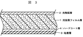
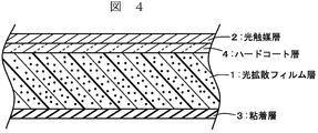
1:光拡散フィルム層
2:光触媒層
3:粘着層
4:ハードコート層
2:光触媒層
3:粘着層
4:ハードコート層
以下、本発明に係るポリアリレート系光拡散積層フィルムについて、実施形態を挙げながら詳細に説明する。ただし、これら実施形態は、本発明に係る好適な適用例であって本発明を限定するものではない。なお、この明細書において「樹脂」とは、専ら高分子化合物を意味しているものである。
本発明の第1の実施態様である図1には、光拡散フィルム層1の片面に光触媒層2を有し、もう一方の面に粘着層3を有したポリアリレート系光拡散積層フィルムが示されている。光拡散フィルム層1はポリアリレート系樹脂の中に光拡散材が分散したものである。
本発明の第2の実施態様である図2には、光拡散フィルム層1の両面にハードコート層4・4を有し、さらにその最表面の片面に光触媒層2を有し、もう一方の最表面に粘着層3を有したポリアリレート系光拡散積層フィルムが示されている。
本発明の第3の実施態様である図3には、光拡散フィルム層1の片面にハードコート層4を有し、さらにその最表面に粘着層3を有し、光拡散フィルム層1のもう一方の面に光触媒層2を有したポリアリレート系光拡散積層フィルムが示されている。
本発明の第4の実施態様である図4には、光拡散フィルム層1の片面にハードコート層4を有し、さらにその最表面に光触媒層2を有し、光拡散フィルム層1のもう一方の面に粘着層3を有したポリアリレート系光拡散積層フィルムが示されている。
(1:光拡散フィルム層)
本発明の光拡散フィルム層を構成するポリアリレート系樹脂は、特に制限されるものではなく、光学用途に用いることができるポリアリレートとして公知のものを使用することができる。ポリアリレート系樹脂は、光拡散フィルム層のベースとして多用されていたポリカーボネートやポリエチレンテレフタレートフィルムよりも、耐摩耗性、低複屈折が優れており、特に光源からの発熱が大きいLED光源に使用するのに十分な耐熱性がある。
本発明の光拡散フィルム層を構成するポリアリレート系樹脂は、特に制限されるものではなく、光学用途に用いることができるポリアリレートとして公知のものを使用することができる。ポリアリレート系樹脂は、光拡散フィルム層のベースとして多用されていたポリカーボネートやポリエチレンテレフタレートフィルムよりも、耐摩耗性、低複屈折が優れており、特に光源からの発熱が大きいLED光源に使用するのに十分な耐熱性がある。
ポリアリレート系樹脂は二価フェノールと芳香族ジカルボン酸との重合物からなる芳香族ポリエステル樹脂であり、このようなポリアリレート系樹脂には、例えばユニチカ社製U-100、P-1001、P-1001Aなどが存在する。
光拡散フィルム層としてポリアリレート系樹脂に添加されて分散する光拡散材は、シリコーン系微粒子が好ましい。例えば信越化学工業社製シリコーンパウダーX-52-7077、KSP-300、KMP-597、X-52-1621などが使用できる。これらは、1種を単独で使用してもよいし、2種類以上を併用してもよい。
シリコーン系微粒子からなる光拡散材の平均粒径は0.05μm以上10μm以下が好ましく、さらには0.1μm以上8μm以下が好ましい。平均粒径を0.1μm以上5μm以下とすることで、十分な光の透過率と、製造過程における十分な耐傷性、十分な光拡散能を発現するとともに、より均一に形成することができる。
シリコーン系微粒子からなる光拡散材の添加量は、100質量部のポリアリレート系樹脂(固形分)に対して、1質量部以上300質量部以下とすることが好ましく、より好ましくは5質量部以上200質量部以下とする。微粒子の添加量をこの範囲とすることによって、LED光源の光拡散性と光透過率との両立が可能となる。添加量を1質量部以下では、LED光源の光拡散性が十分に得られず、300質量部以下とすると、LED光源の光透過率を十分に得ることができず、フィルムが非常に脆くなってしまうきらいがある。
光拡散フィルム層のポリアリレート系樹脂と、光拡散材であるシリコーン系微粒子との屈折率差が0.01以上0.3以下であることが好ましい。屈折率差が0.01以上0.3以下とすることで、LED光源の光拡散性と光線透過率を向上することができる。
光拡散フィルム層は、ポリアリレート系樹脂に光拡散材を添加混練し分散させたものを製膜して得られる。製膜には、経済性の点から溶融押し出し成型法が好ましい。溶融押し出し成型法で実施する場合の、その成型方法等は特に制限されない。例えばTダイ法及びインフレーション法のいずれでもよい。また、未延伸フィルムでもよいが、溶融押し出し成型中又は成型後に120~160℃の温度範囲内で、少なくとも一方向に延伸されてなることが好ましい。この延伸操作によりフィルムの耐熱性や光学特性の向上を図ることができる。
光拡散フィルム層の厚みは、目的に応じて任意で選べるが、LED照明用途としては150μm以上であることが好ましい。より好ましくは、200μm以上である。さらにはポリアリレート系光拡散積層フィルムの剛性が要求される用途においては250μm以上とすることが好ましい。なお、光拡散フィルム層は、他の層(ハードコート層、光触媒層、粘着層)のいずれの層よりも厚い。
(2:光触媒層)
本発明のポリアリレート系光拡散積層フィルムにおける光触媒層としては、光触媒粒子と水溶性バインダーからなる光触媒塗工液を塗布して乾燥硬化した光触媒膜が好適である。ポリアリレート系光拡散積層フィルムに防汚効果をもたらす。
本発明のポリアリレート系光拡散積層フィルムにおける光触媒層としては、光触媒粒子と水溶性バインダーからなる光触媒塗工液を塗布して乾燥硬化した光触媒膜が好適である。ポリアリレート系光拡散積層フィルムに防汚効果をもたらす。
光触媒粒子としては、現在上市されている酸化チタン系、酸化タングステン系、酸化亜鉛系、酸化ニオブ系等、n型半導体である金属酸化物の結晶微粒子が使用できる。例えば、アナターゼ型の二酸化チタン(TiO2)、ルチル型の二酸化チタン(TiO2)、三酸化タングステン(WO3)、酸化亜鉛(ZnO)、Gaドープ酸化亜鉛(GZO)、酸化ニオブ(Nb2O5)等が使用し得る。中でも、可視光活性の高いものとしてこれら金属酸化物の結晶内に窒素、硫黄、リン、炭素等をドーピングしたもの、又は表面に銅、鉄、ニッケル、金、銀、白金、炭素等を担持したものが好適に使用し得る。更に詳しくは、白金を担持したルチル型酸化チタン、鉄を担持したルチル型酸化チタン、銅を担持したルチル型酸化チタン、水酸化銅を担持したルチル型酸化チタン、金を担持したアナターゼ型酸化チタン、白金を担持した三酸化タングステン等である。更に、該微粒子の一次粒子径が微細なもの、即ち一次粒径が1~100nmの範囲、好ましくは1~50nmの範囲にあるものが好適に使用される。一次粒径が100nmより大きいと塗膜の透明度が低下し外観を損ねることがある。
このような、可視光活性が高い光触媒微粒子としては、MPT-623(可視光応答光触媒、粉体状、白金を担持したルチル型二酸化チタン;石原産業(株)製)、MPT-625(可視光応答光触媒、粉体状、鉄を担持したルチル型二酸化チタン;石原産業(株)製)等が挙げられる。
光触媒塗工液の水溶性バインダーは、水、塩基性化合物、および極性溶媒中で、下記式(1)で示される珪素アルコキシド、またはその縮合物を加水分解する手法で好適に得られる。
Si(OR)X(OH)4-X・・・(1)
Si(OR)X(OH)4-X・・・(1)
式(1)中Rは、独立に水素原子または官能基である。Rは互いに同一であっても異なっていても良い。官能基Rとして具体的には、例えば、水素原子(H)、メチル基(CH3)、エチル基(CH2CH3)、プロピル基(CH2CH2CH3)、イソプロピル基(CH2(CH3)CH3)、ブチル基(CH2CH2CH2CH3)、アルコキシシリル基(Si(OCH2CH2)3)などが挙げられる。
これらのうち、テトラメトキシシラン(上記Rが全てメチル)、テトラエトキシシラン(上記Rが全てエチル)が特に好ましい。
光触媒塗工液の水溶性バインダーに含まれ、珪素アルコキシドの加水分解に使用される塩基性化合物としては、下記式(2)で示される
RX-NH4-X・・・(2)
RX-NH4-X・・・(2)
式(2)中Rは独立に水素原子または官能基である。Rは互いに同一であっても異なっていても良い。官能基Rとして具体的には、例えば、水素原子(H)、メチル基(CH3)、エチル基(CH2CH3)、プロピル基(CH2CH2CH3)、イソプロピル基(CH2(CH3)CH3)、ブチル基(CH2CH2CH2CH3)、メチロール基(CH2OH)、エチロール基(CH2CH2OH)が挙げられる。なお、水素原子以外の官能基で置換され、下記式(3)で示す4級アミンの形態を取る。
R4N+X-・・・(3)
R4N+X-・・・(3)
式(3)のX-で表される対アニオンとの塩類になっていても良い。具体的に、Xとしてヒドロキシ基(OH)、ハロゲン(F、Cl、Br、I)等が挙げられる。これらのうち、テトラメチルアンモニウムヒドロキシドが好適に使用できる。
水溶性バインダーの一部で、ケイ素アルコキシド、塩基性化合物と共に反応に供される極性溶媒として、水、アルコール類(例えば、メタノール、エタノール、イソプロパノール)、グリコール類(例えば、グリセリン、メチルセロソルブ、エチルセロソルブ、プロピルセロソルブ、またはこれらの酢酸エステル類)、ケトン類(例えば、アセトン、ダイアセトンアルコール、アセチルアセトン、メチルエチルケトン)が挙げられる。上記極性溶媒は、1種単独又は2種以上を併用してもよい。これらのうち、アセトンが好適に使用できる。
ケイ素アルコキシド、塩基性化合物、極性溶媒、水を混合・攪拌し、得られた生成物を水にまたはアルコールに溶解し、酸添加またはイオン交換によってpH=5~8に調整したものを、バインダー液として使用し、ケイ素アルコキシドの加水分解がなされる。
光触媒塗工液は、光触媒粒子が分散され、かつ上記条件にて調製した加水分解シリケートが溶解または分散している。あらかじめ溶媒に光触媒粒子を分散させた光触媒分散液を調製し、混合撹拌することで調製される。このような光触媒塗工液は、具体的には信越化学工業社製 TA-801-G、TA-802-G、TA-803-Gなどがある。
光触媒塗工液中の光触媒固形分濃度は、0.01~10質量%であり、好ましくは0.1~5質量%である。光触媒固形分濃度が0.01質量%より少ないと光触媒による防汚活性が低下することがあり、10質量%より多いと透明性が低下し外観を損ねることがある。また、塗工液中の光触媒と加水分解シリケートの固形分濃度は、光触媒固形分質量:シリケート固形分質量比として、0.05:99.5~99.5:0.05であり、好ましくは5:95~95:5である。光触媒質量比が5より少ないと十分な親水性・酸化分解による防汚活性が得られず、また95より多いと膜の強度が低く剥離、割れが生じることがある。
光触媒塗工液が塗布される基材は、薄膜を形成することができる限り、特に制限されない。光触媒塗工液を基材に塗布するには、従来公知のいずれの方法も用いることができる。具体的には、ディップコーティング法、スピンコーティング法、スプレーコーティング法、印毛塗り法、含浸法、ロール法、ワイヤーバー法、ダイコーティング法、グラビア印刷法、インクジェット法等を利用して塗膜を基材上に形成させることができる。
形成される塗膜の膜厚は、1~500nm、特には、50~300nmの範囲にあることが好ましい。膜厚が薄すぎると強度が低い場合があり、また厚すぎると割れが生じる場合がある。
光触媒塗工液を塗布して塗膜を乾燥硬化させるためには、50~200℃の温度範囲で1~120分間処理することが好ましく、特には、60~110℃の温度範囲で5~60分間処理することが好ましい。
(3:粘着層)
LED光源にポリアリレート系光拡散積層フィルムを貼り付けるための粘着層の材としては、シリコーン粘着材が好適である。
LED光源にポリアリレート系光拡散積層フィルムを貼り付けるための粘着層の材としては、シリコーン粘着材が好適である。
シリコーン粘着材としては、一般的に使用されている加熱硬化型の鎖状のオルガノポリシロキサンと、固体状のシリコーンレジンからなる粘着材を用いることができる。加熱硬化型のシリコーン粘着材としては、有機過酸化物硬化型と白金付加硬化型があるが、基材として延伸性のポリエチレンフイルム、ポリプロピレンフイルムを用いる場合、熱により変形することがあるため、比較的低温で硬化することのできる白金付加硬化型のシリコーン粘着材を用いることが特に好ましい。シリコーン粘着材の硬化条件としては、通常80~150℃である。
有機過酸化物硬化型のシリコーン粘着材は、鎖状のオルガノポリシロキサンと(R3SiO1/2)単位と(SiO2)単位(Rは置換もしくは非置換の一価炭化水素基)からなるオルガノポリシロキサン共重合体レジン((SiO2)単位に対する(R3SiO1/2)単位のモル比が0.5~1.5)とのオルガノポリシロキサン混合物、及び架橋硬化剤としてのベンゾイルパーオキサイド、ビス(4-メチルベンゾイル)パーオキサイド、2,5-ジメチル-2,5-ビス(t-ブチルパーオキシ)ヘキサン等の有機過酸化物を含有するものである。白金付加硬化型のシリコーン粘着材は、鎖状のビニル基含有オルガノポリシロキサン、前記オルガノポリシロキサン共重合体レジン、及び架橋硬化剤としてケイ素結合水素原子を含有するオルガノハイドロジェンポリシロキサン、触媒として塩化白金酸、アルコール変性塩化白金酸、白金のオレフィン錯体、白金のビニルシロキサンとの錯体等の白金族金属系触媒を含有するものである。
このようなシリコーン系粘着材としては、例えば信越化学工業社製 X-40-3270/CAT-PL-50T=100/0.5、X-40-3229/CAT-PL-50T=100/0.5、X-40-3323/CAT-PL-50T=100/0.25などがある。
シリコーン粘着材の層の厚さは、5~100μmであることが好ましく、より好ましくは10~50μmである。
(4:ハードコート層)
本発明のポリアリレート系光拡散積層フィルムに設けられるハードコート層は、シリコーン系ハードコート材が好ましい。形成の作業性の面から、光硬化性シリコーン系ハードコート材であることがさらに好ましい。光反応性基含有シロキサン化合物、(メタ)アクリル基含有化合物、ラジカル系光重合開始剤から形成される。具体的には、信越化学工業社 KP-1001、X-12-2437などがある。この塗布液からなる塗布膜を光拡散フィルム層上にコーティングし、UVランプ照射により硬化させ、ハードコート層を得る。
本発明のポリアリレート系光拡散積層フィルムに設けられるハードコート層は、シリコーン系ハードコート材が好ましい。形成の作業性の面から、光硬化性シリコーン系ハードコート材であることがさらに好ましい。光反応性基含有シロキサン化合物、(メタ)アクリル基含有化合物、ラジカル系光重合開始剤から形成される。具体的には、信越化学工業社 KP-1001、X-12-2437などがある。この塗布液からなる塗布膜を光拡散フィルム層上にコーティングし、UVランプ照射により硬化させ、ハードコート層を得る。
ハードコート層の形成方法は特に制限されるものではなく、公知の塗布機を目的に応じて適宜選択して塗布すればよい。例えば、リバースロールコータ、ワイヤーバー、カーテンコータによる塗布が挙げられる。形成された被膜の膜厚は、0.1~50μm、特に0.5~30μmの範囲にあることが好ましい。膜厚が薄すぎると耐摩耗性が低下する場合があり、また厚すぎると耐クラック性が低下する場合がある。
ハードコート層を硬化させるための光源としては、通常、200~450nmの範囲の波長の光を含む光源、例えば高圧水銀灯、超高圧水銀灯、メタルハライドランプ、キセノン灯、カーボンアーク灯等を使用することができる。照射量は特に制限されないが、10~5,000mJ/cm2、特に20~2,000mJ/cm2であることが好ましい。硬化時間は、通常0.5秒~2分、好ましくは1秒~1分である。
本発明のポリアリレート系光拡散積層フィルムは、耐傷性を求めない場合には、ハードコート層を必ずしも備える必要はないし、光拡散フィルム層の片面にのみ備えるなど任意である。
ポリアリレート系光拡散積層フィルムの各層には、さらに添加剤を含んでもよい。さらに別の層を設けて、設けた層に添加剤を含ませてもよい。また、複数の層に含ませてもよい。中でも、光拡散フィルム層のポリアリレート系樹脂に含ませることが好ましい。他の層よりも厚いポリアリレート系樹脂に含有させることにより、添加剤濃度が低くても十分な含有効果が得られるからである。例えば添加剤として後述のように紫外線吸収剤を用いた場合には、ポリアリレート系樹脂に含ませることにより、紫外線吸収剤の濃度が低くても十分な紫外線吸収効果が得られるからである。
第1の添加剤としては、紫外線吸収剤があり、第2の添加剤としては、光や熱によって生じる酸化を防止するための酸化防止剤やHALS(ヒンダードアミン光安定剤,Hinderd Amine Light Stabilizer)がある。第1の添加剤と第2の添加剤とは互いに異なる層に含ませてもよいし、同一の層中に含ませてもよい。
以下、本発明の実施例を挙げてより具体的に説明するが、本発明はこれら実施例によって制限を受けるものではない。本発明の趣旨に適合し得る範囲で適宜変更を加えて実施することも可能であり、いずれも本発明の技術的範囲に含まれる。
なお、実施例で採用した測定・評価方法は次の通りである。また、実施例中で「部」とあるのは断りのない限り「質量部」を意味し、「%」とあるのは断りのない限り「質量%」を意味する。
1.透過光の拡散度の測定
自動変角光度計(GP-200:株式会社村上色彩研究所製)を用いて測定を行う。
透過測定モード、光線入射角:60°、受光角度:-90°~90°、SENSITIVITY:150、HIGH VOLTON:500、フィルター:ND10使用、光束絞り:10.5mm(VS-1 3.0)、受光絞り:9.1mm(VS-3 4.0)及び変角間隔0.1度の条件で測定し得られる透過ピークの立ち上がりの開始角度より立下りの終了角度までの角度幅(度)及びピーク高さを求める。角度幅が拡散度であり、ピーク高さが透過度である。
自動変角光度計(GP-200:株式会社村上色彩研究所製)を用いて測定を行う。
透過測定モード、光線入射角:60°、受光角度:-90°~90°、SENSITIVITY:150、HIGH VOLTON:500、フィルター:ND10使用、光束絞り:10.5mm(VS-1 3.0)、受光絞り:9.1mm(VS-3 4.0)及び変角間隔0.1度の条件で測定し得られる透過ピークの立ち上がりの開始角度より立下りの終了角度までの角度幅(度)及びピーク高さを求める。角度幅が拡散度であり、ピーク高さが透過度である。
2.全光線透過率
日本電色工業株式会社製ヘーズ測定器「NDH-2000」を用いて、JIS K 7105-1981に準拠して測定した。
日本電色工業株式会社製ヘーズ測定器「NDH-2000」を用いて、JIS K 7105-1981に準拠して測定した。
3.フィルム外観
フィルムの表面を目視で観察して、うねり状模様の有無などの外観不良の有無で判定した。該外観不良のないものを良、あるものを不良とした。
フィルムの表面を目視で観察して、うねり状模様の有無などの外観不良の有無で判定した。該外観不良のないものを良、あるものを不良とした。
4.防汚性の確認
防汚性は、10μmol/Lに調整したメチレンブルー水溶液を、5cm×5cmに切り出した拡散フィルム上に1mL塗り広げ、試料表面での光量が10000Luxとなるように白色LEDの光を3時間照射したのち、青色が消色したものを○、変化の見られなかったものを×とした。
防汚性は、10μmol/Lに調整したメチレンブルー水溶液を、5cm×5cmに切り出した拡散フィルム上に1mL塗り広げ、試料表面での光量が10000Luxとなるように白色LEDの光を3時間照射したのち、青色が消色したものを○、変化の見られなかったものを×とした。
(実施例1)
ポリアリレート樹脂(ユニチカ社製、U-100)100質量部、シリコーンパウダー(信越化学工業社製、X-52-7077;平均粒子径5μm)10質量部を予め2軸の押し出し機で溶融押し出しすることにより得た混練されたポリアリレート系樹脂組成物を、60mmφ単軸押出機(L/D;22)内で樹脂温度350℃にて溶融混合してTダイで押出した後、130℃のキャスティングロールで冷却することにより未延伸シートを得た。次いでこの未延伸シートを縦延伸機のロール周速差を利用して延伸温度120℃で4倍に延伸して厚み250μmのポリアリレート系光拡散フィルムを得た。このポリアリレート系光拡散フィルムの片面にワイヤーバー法により溶媒に光触媒粒子が分散され、かつ水溶性シリケートバインダーを含有している光触媒塗工液(信越化学工業社製、TA-801-G)を塗布し、100℃のオーブン中で30分間熱処理し、厚さ200nmの光触媒層を得た。ポリアリレート系光拡散フィルムのもう一方の面にはワイヤーバー法によりシリコーン系粘着材(信越化学工業社製、X-40-3270/CAT-PL-50T=100/0.5)を塗布し、130℃のオーブン中で2分間熱処理し、厚さ30μmの粘着層を得た。
ポリアリレート樹脂(ユニチカ社製、U-100)100質量部、シリコーンパウダー(信越化学工業社製、X-52-7077;平均粒子径5μm)10質量部を予め2軸の押し出し機で溶融押し出しすることにより得た混練されたポリアリレート系樹脂組成物を、60mmφ単軸押出機(L/D;22)内で樹脂温度350℃にて溶融混合してTダイで押出した後、130℃のキャスティングロールで冷却することにより未延伸シートを得た。次いでこの未延伸シートを縦延伸機のロール周速差を利用して延伸温度120℃で4倍に延伸して厚み250μmのポリアリレート系光拡散フィルムを得た。このポリアリレート系光拡散フィルムの片面にワイヤーバー法により溶媒に光触媒粒子が分散され、かつ水溶性シリケートバインダーを含有している光触媒塗工液(信越化学工業社製、TA-801-G)を塗布し、100℃のオーブン中で30分間熱処理し、厚さ200nmの光触媒層を得た。ポリアリレート系光拡散フィルムのもう一方の面にはワイヤーバー法によりシリコーン系粘着材(信越化学工業社製、X-40-3270/CAT-PL-50T=100/0.5)を塗布し、130℃のオーブン中で2分間熱処理し、厚さ30μmの粘着層を得た。
このようにして得られた実施例1のポリアリレート系光拡散積層フィルムは、図1に示す断面を持ち、その測定値、特性を表1に示す。このポリアリレート系光拡散積層フィルムは、LED光源の隠蔽性は良好で、かつ、透過度、拡散度、全光線透過率いずれも優れており、さらにフィルムの外観が良好であり高品質であった。
(実施例2)
実施例1で調製した一軸延伸フィルムを、さらに横方向に3倍に延伸すること以外は実施例1と同様の工程でポリアリレート系光拡散積層フィルムを得た。このようにして得られた実施例2のポリアリレート系光拡散積層フィルムは、図1に示す断面を持ち、その測定値、特性を表1に示す。このポリアリレート系光拡散積層フィルムはLED光源の隠蔽性は良好で、かつ、透過度、拡散度、全光線透過率いずれも優れており、さらにフィルムの外観が良好であり高品質であった。
実施例1で調製した一軸延伸フィルムを、さらに横方向に3倍に延伸すること以外は実施例1と同様の工程でポリアリレート系光拡散積層フィルムを得た。このようにして得られた実施例2のポリアリレート系光拡散積層フィルムは、図1に示す断面を持ち、その測定値、特性を表1に示す。このポリアリレート系光拡散積層フィルムはLED光源の隠蔽性は良好で、かつ、透過度、拡散度、全光線透過率いずれも優れており、さらにフィルムの外観が良好であり高品質であった。
(実施例3)
実施例1で調製した一軸延伸フィルムの両面にワイヤーバー法により光硬化型シリコーン系ハードコート材(信越化学工業社、KP-1001)を塗布し、高圧水銀灯にて375nmの波長の光を1200mJ/cm2、1分照射し、厚さ3μmのハードコート層を得た。さらにこのポリアリレート系光拡散フィルムの片面にワイヤーバー法により溶媒に光触媒粒子が分散され、かつ水溶性シリケートバインダーを含有している光触媒塗工液(信越化学工業社製、TA-801-G)を塗布し、100℃のオーブン中で30分間熱処理し、厚さ200nmの光触媒層を得た。ポリアリレート系光拡散フィルムのもう一方の面にはワイヤーバー法によりシリコーン系粘着材(信越化学工業社製、X-40-3270/CAT-PL-50T=100/0.5)を塗布し、130℃のオーブン中で2分間熱処理し、厚さ30μmの粘着層を得た。このようにして得られた実施例3のポリアリレート系光拡散積層フィルムは、図2に示す断面を持ち、その測定値、特性を表1に示す。このポリアリレート系光拡散積層フィルムはLED光源の隠蔽性は良好で、かつ、透過度、拡散度、全光線透過率いずれも優れており、さらにフィルムの外観が良好であり高品質であった。
実施例1で調製した一軸延伸フィルムの両面にワイヤーバー法により光硬化型シリコーン系ハードコート材(信越化学工業社、KP-1001)を塗布し、高圧水銀灯にて375nmの波長の光を1200mJ/cm2、1分照射し、厚さ3μmのハードコート層を得た。さらにこのポリアリレート系光拡散フィルムの片面にワイヤーバー法により溶媒に光触媒粒子が分散され、かつ水溶性シリケートバインダーを含有している光触媒塗工液(信越化学工業社製、TA-801-G)を塗布し、100℃のオーブン中で30分間熱処理し、厚さ200nmの光触媒層を得た。ポリアリレート系光拡散フィルムのもう一方の面にはワイヤーバー法によりシリコーン系粘着材(信越化学工業社製、X-40-3270/CAT-PL-50T=100/0.5)を塗布し、130℃のオーブン中で2分間熱処理し、厚さ30μmの粘着層を得た。このようにして得られた実施例3のポリアリレート系光拡散積層フィルムは、図2に示す断面を持ち、その測定値、特性を表1に示す。このポリアリレート系光拡散積層フィルムはLED光源の隠蔽性は良好で、かつ、透過度、拡散度、全光線透過率いずれも優れており、さらにフィルムの外観が良好であり高品質であった。
(比較例1)
実施例1の方法において、シリコーンパウダーをアクリルパウダー(綜研化学社製、ケミスノー MX-500;平均粒子径5μm)10質量部に変更する以外は、実施例1と同様の方法で光拡散フィルムを得た。得られた比較例1のポリアリレート系光拡散積層フィルムの特性を表1に示す。このポリアリレート系光拡散積層フィルムは、拡散度は優れているが、全光線透過率が良くなかった。
実施例1の方法において、シリコーンパウダーをアクリルパウダー(綜研化学社製、ケミスノー MX-500;平均粒子径5μm)10質量部に変更する以外は、実施例1と同様の方法で光拡散フィルムを得た。得られた比較例1のポリアリレート系光拡散積層フィルムの特性を表1に示す。このポリアリレート系光拡散積層フィルムは、拡散度は優れているが、全光線透過率が良くなかった。
(比較例2)
厚み250μmのポリアリレートフィルムの片面にアクリル樹脂ビーズよりなる拡散層を塗工法で積層することにより光拡散フィルムを得た。得られた比較例2の光拡散フィルムの特性を表1に示す。この光拡散フィルムはいずれもが拡散度比が低く、かつ透過度と拡散度のバランスが良くなかった。
厚み250μmのポリアリレートフィルムの片面にアクリル樹脂ビーズよりなる拡散層を塗工法で積層することにより光拡散フィルムを得た。得られた比較例2の光拡散フィルムの特性を表1に示す。この光拡散フィルムはいずれもが拡散度比が低く、かつ透過度と拡散度のバランスが良くなかった。
(比較例3)
厚み250μmのポリアリレートフィルムの片面にポリスチレンポリマービーズよりなる拡散層を塗工法で積層することにより光拡散フィルムを得た。得られた比較例3の光拡散フィルムの特性を表1に示す。この光拡散フィルムはいずれもが拡散度比が低く、かつ透過度と拡散度のバランスが良くなかった。また、表面にうねり状模様の不良が観察された。
厚み250μmのポリアリレートフィルムの片面にポリスチレンポリマービーズよりなる拡散層を塗工法で積層することにより光拡散フィルムを得た。得られた比較例3の光拡散フィルムの特性を表1に示す。この光拡散フィルムはいずれもが拡散度比が低く、かつ透過度と拡散度のバランスが良くなかった。また、表面にうねり状模様の不良が観察された。

Claims (13)
- 光触媒層と、ポリアリレート系樹脂の中にシリコーン系微粒子からなる光拡散材が分散したフィルム層と、粘着層とを有し、該光触媒層が一方の面の最外層であり、該粘着層がもう一方の面の最外層であることを特徴とするポリアリレート系光拡散積層フィルム。
- 前記フィルム層と前記光触媒層との間、および前記フィルム層と前記粘着層との間の、少なくとも一方の間にハードコート層を有することを特徴とする請求項1に記載のポリアリレート系光拡散積層フィルム。
- 前記ハードコート層が、シリコーン系ハードコート材よりなることを特徴とする請求項2に記載のポリアリレート系光拡散積層フィルム。
- 前記シリコーン系ハードコート材が、光硬化性シリコーン系ハードコート材であることを特徴とする請求項3に記載のポリアリレート系光拡散積層フィルム。
- 前記シリコーン系微粒子からなる光拡散材が、平均粒径0.05μm以上10μm以下であることを特徴とする請求項1に記載のポリアリレート系光拡散積層フィルム。
- 前記ポリアリレート系樹脂と前記シリコーン系微粒子との屈折率差が、0.01以上0.3以下であることを特徴とする請求項5に記載のポリアリレート系光拡散積層フィルム。
- 前記粘着層が、シリコーン系粘着材よりなることを特徴とする請求項1または2に記載のポリアリレート系光拡散積層フィルム。
- 前記光触媒層が、光触媒粒子と水溶性バインダーを含む塗工液を塗布して形成されたことを特徴とする請求項1または2に記載のポリアリレート系光拡散積層フィルム。
- 前記光触媒粒子が、n型半導体性を有する金属酸化物の結晶微粒子の上に、バナジウム、マンガン、鉄、コバルト、ニッケル、銅、亜鉛、ニオブ、モリブデン、ルテニウム、ロジウム、銀、スズ、タングステン、白金、金からなる群から選ばれる金属、金属の酸化物、または/および金属の化合物を担持した光触媒粒子であることを特徴とする請求項8に記載のポリアリレート系光拡散積層フィルム。
- 前記水溶性バインダーが、加水分解性ケイ素化合物を、水、塩基性化合物および極性溶媒の混合溶剤中で加水分解した化合物を含有することを特徴とする請求項8に記載のポリアリレート系光拡散積層フィルム。
- 請求項1から10のいずれかに記載のポリアリレート系光拡散積層フィルムの全光透過率が、60%以上であることを特徴とするポリアリレート系光拡散積層フィルム。
- LED照明に使用されることを特徴とする請求項1~11のいずれかに記載のポリアリレート系光拡散積層フィルム。
- LED表示装置に使用されることを特徴とする請求項1~11のいずれかに記載のポリアリレート系光拡散積層フィルム。
Applications Claiming Priority (2)
| Application Number | Priority Date | Filing Date | Title |
|---|---|---|---|
| JP2011-138683 | 2011-06-22 | ||
| JP2011138683A JP2013007782A (ja) | 2011-06-22 | 2011-06-22 | ポリアリレート系光拡散フィルム |
Publications (1)
| Publication Number | Publication Date |
|---|---|
| WO2012176665A1 true WO2012176665A1 (ja) | 2012-12-27 |
Family
ID=47422505
Family Applications (1)
| Application Number | Title | Priority Date | Filing Date |
|---|---|---|---|
| PCT/JP2012/065069 Ceased WO2012176665A1 (ja) | 2011-06-22 | 2012-06-13 | ポリアリレート系光拡散フィルム |
Country Status (3)
| Country | Link |
|---|---|
| JP (1) | JP2013007782A (ja) |
| TW (1) | TWI461297B (ja) |
| WO (1) | WO2012176665A1 (ja) |
Cited By (1)
| Publication number | Priority date | Publication date | Assignee | Title |
|---|---|---|---|---|
| JP2024007811A (ja) * | 2022-07-06 | 2024-01-19 | シャープ株式会社 | 光触媒コーティング剤、光触媒フィルム、表示装置及びバインダーの合成方法 |
Families Citing this family (1)
| Publication number | Priority date | Publication date | Assignee | Title |
|---|---|---|---|---|
| JP6205604B2 (ja) * | 2014-01-30 | 2017-10-04 | 平岡織染株式会社 | 光源カバー用可撓性膜材 |
Citations (5)
| Publication number | Priority date | Publication date | Assignee | Title |
|---|---|---|---|---|
| JP2008155448A (ja) * | 2006-12-22 | 2008-07-10 | Kimoto & Co Ltd | 光触媒シート |
| JP2008304562A (ja) * | 2007-06-05 | 2008-12-18 | Mitsubishi Plastics Inc | 反射防止層転写用積層ポリエステルフィルム |
| JP2008310267A (ja) * | 2007-06-18 | 2008-12-25 | Daio Paper Corp | 光拡散性粘着シート |
| JP2009258720A (ja) * | 2008-03-28 | 2009-11-05 | Fujifilm Corp | 透明支持体、光学フィルム、偏光板、および画像表示装置 |
| JP2011000723A (ja) * | 2009-06-16 | 2011-01-06 | Konica Minolta Holdings Inc | 遮熱性物品、遮熱性物品の製造方法及び屋外用建築部材 |
-
2011
- 2011-06-22 JP JP2011138683A patent/JP2013007782A/ja not_active Withdrawn
-
2012
- 2012-06-13 WO PCT/JP2012/065069 patent/WO2012176665A1/ja not_active Ceased
- 2012-06-20 TW TW101121994A patent/TWI461297B/zh not_active IP Right Cessation
Patent Citations (5)
| Publication number | Priority date | Publication date | Assignee | Title |
|---|---|---|---|---|
| JP2008155448A (ja) * | 2006-12-22 | 2008-07-10 | Kimoto & Co Ltd | 光触媒シート |
| JP2008304562A (ja) * | 2007-06-05 | 2008-12-18 | Mitsubishi Plastics Inc | 反射防止層転写用積層ポリエステルフィルム |
| JP2008310267A (ja) * | 2007-06-18 | 2008-12-25 | Daio Paper Corp | 光拡散性粘着シート |
| JP2009258720A (ja) * | 2008-03-28 | 2009-11-05 | Fujifilm Corp | 透明支持体、光学フィルム、偏光板、および画像表示装置 |
| JP2011000723A (ja) * | 2009-06-16 | 2011-01-06 | Konica Minolta Holdings Inc | 遮熱性物品、遮熱性物品の製造方法及び屋外用建築部材 |
Cited By (1)
| Publication number | Priority date | Publication date | Assignee | Title |
|---|---|---|---|---|
| JP2024007811A (ja) * | 2022-07-06 | 2024-01-19 | シャープ株式会社 | 光触媒コーティング剤、光触媒フィルム、表示装置及びバインダーの合成方法 |
Also Published As
| Publication number | Publication date |
|---|---|
| JP2013007782A (ja) | 2013-01-10 |
| TWI461297B (zh) | 2014-11-21 |
| TW201318852A (zh) | 2013-05-16 |
Similar Documents
| Publication | Publication Date | Title |
|---|---|---|
| JP4920513B2 (ja) | フィルム積層体及びその製造方法 | |
| TWI556269B (zh) | 透明導體、製備其的方法以及包括其的光學顯示器 | |
| WO2013111735A1 (ja) | 光学フィルム | |
| TWI431373B (zh) | A semi-permeable reflective sheet and a backlight unit using the same | |
| CN101929655B (zh) | 半透射性反射片及使用其的背光单元 | |
| JP2018524641A (ja) | 反射防止フィルムおよびディスプレイ装置 | |
| JP2008287072A (ja) | 防眩性フィルム及びそれを用いた反射防止フィルム | |
| TW200804082A (en) | Thin film laminate and method for fabricating the same | |
| WO2012060267A1 (ja) | ハードコート層付ポリカーボネート | |
| WO2015198762A1 (ja) | 光学反射フィルム、光学反射フィルムの製造方法、およびそれを用いる光学反射体 | |
| JP2010125719A (ja) | 飛散防止性能付きガラス | |
| CN105722925A (zh) | 涂料组合物及使用了该涂料组合物的光扩散部件 | |
| TW200809137A (en) | White reflective film | |
| JP4905822B2 (ja) | コーティング組成物、その塗膜、反射防止膜、及び画像表示装置 | |
| CN107405869A (zh) | 具有透明粘合剂层的导电膜叠层体 | |
| JP2023513542A (ja) | 光学フィルムおよびこれを含むマイクロledディスプレイ | |
| JP7343273B2 (ja) | 防眩性フィルム、防眩性フィルムの製造方法、光学部材および画像表示装置 | |
| KR20170037953A (ko) | 유기 el 발광장치 | |
| TW201127916A (en) | Multilayer film and production method of the same | |
| JP2009103734A (ja) | 防眩性フィルム、偏光板、および画像表示装置 | |
| JP2013007782A (ja) | ポリアリレート系光拡散フィルム | |
| JP2014065172A (ja) | ハードコートフィルム付アクリル樹脂 | |
| JP2009036910A (ja) | 光学フィルム | |
| JP2009103892A (ja) | 光拡散体 | |
| JP2022169991A (ja) | 成型拡散積層フィルム |
Legal Events
| Date | Code | Title | Description |
|---|---|---|---|
| 121 | Ep: the epo has been informed by wipo that ep was designated in this application |
Ref document number: 12803436 Country of ref document: EP Kind code of ref document: A1 |
|
| NENP | Non-entry into the national phase |
Ref country code: DE |
|
| 122 | Ep: pct application non-entry in european phase |
Ref document number: 12803436 Country of ref document: EP Kind code of ref document: A1 |