WO2012176524A1 - イオン発生装置およびイオン発生方法 - Google Patents
イオン発生装置およびイオン発生方法 Download PDFInfo
- Publication number
- WO2012176524A1 WO2012176524A1 PCT/JP2012/058871 JP2012058871W WO2012176524A1 WO 2012176524 A1 WO2012176524 A1 WO 2012176524A1 JP 2012058871 W JP2012058871 W JP 2012058871W WO 2012176524 A1 WO2012176524 A1 WO 2012176524A1
- Authority
- WO
- WIPO (PCT)
- Prior art keywords
- discharge
- electrode
- voltage
- ions
- discharge electrode
- Prior art date
- Legal status (The legal status is an assumption and is not a legal conclusion. Google has not performed a legal analysis and makes no representation as to the accuracy of the status listed.)
- Ceased
Links
Images





Classifications
-
- H—ELECTRICITY
- H01—ELECTRIC ELEMENTS
- H01T—SPARK GAPS; OVERVOLTAGE ARRESTERS USING SPARK GAPS; SPARKING PLUGS; CORONA DEVICES; GENERATING IONS TO BE INTRODUCED INTO NON-ENCLOSED GASES
- H01T23/00—Apparatus for generating ions to be introduced into non-enclosed gases, e.g. into the atmosphere
Definitions
- the present invention relates to an ion generator that discharges ions in the air and discharges ions into the space, and an electric device including the same.
- the ion generator generates positive ions or negative ions by applying a voltage between the discharge electrode and the induction electrode and generating a corona discharge at the discharge electrode.
- ion generators There are two types of commercially available ion generators: one that generates only negative ions and one that generates both positive ions and negative ions. Ion generators that generate only negative ions are said to have a relaxing effect, and devices that generate both positive and negative ions decompose fungi and viruses floating in the air, decompose odor components, remove static electricity, etc. It is said that there is an effect. Moreover, such an effect is further enhanced as the amount of ions generated is increased.
- Patent Document 1 describes an ion generating element having a discharge electrode and an induction electrode.
- the induction electrode is made of a metal plate and has a through hole at a position corresponding to the discharge electrode.
- the discharge electrode has a needle-like shape, and is arranged so that its tip is located at the center of the through hole of the induction electrode.
- Patent Document 2 In Japanese Patent Application Laid-Open No. 2004-363088 (Patent Document 2), as shown in FIG. 9, discharging is performed by applying a plus or minus pulse voltage to both the discharge electrode and the induction electrode.
- FIG. 9A shows the voltage applied to the induction electrode
- FIG. 9B shows the voltage applied to the discharge electrode.
- Patent Document 2 when a positive or negative voltage is applied to both the discharge electrode and the induction electrode during discharge, ions generated at the discharge electrode are applied. Is expected to be repelled by the potential of the induction electrode and difficult to be collected by the induction electrode. However, when the discharge is completed, the potential of the induction electrode becomes 0, and ions existing in the vicinity of the electrode are similarly collected by the induction electrode.
- the present invention has been made in view of the above problems in the prior art, and its purpose is to prevent the generated ions from being collected on the discharge electrode and the induction electrode, thereby increasing the concentration of the conventional technique.
- An apparatus and method for generating ions is provided.
- An ion generator has a discharge electrode and an induction electrode facing the discharge electrode, and discharge occurs between a DC power source that applies a DC voltage to the discharge electrode and the discharge electrode of the induction electrode.
- a pulse power supply that applies a first voltage and a second voltage at which discharge stops is provided.
- the second voltage is characterized by having the same polarity as the DC voltage applied to the discharge electrode.
- the absolute value of the second voltage is preferably a value greater than one half of the absolute value of the DC voltage applied to the discharge electrode.
- the second voltage is preferably substantially the same voltage as the DC voltage applied to the discharge electrode.
- the duty of the pulse power supply is preferably 0.2 or less. Moreover, it is preferable that the frequency of a pulse power supply is 700 Hz or more.
- the discharge time per cycle is preferably 150 ⁇ s or less.
- the non-discharge time per cycle is preferably 150 ⁇ s or more and 1500 ⁇ s or less.
- the ion generation method according to the present invention is an ion generation method using a discharge electrode and an induction electrode facing the discharge electrode, wherein a DC voltage is applied to the discharge electrode and a discharge is generated between the induction electrode and the discharge electrode. And a second voltage at which the discharge stops, and the second voltage has the same polarity as the DC voltage applied to the discharge electrode.
- the ion generating apparatus and the ion generating method according to the present invention it is possible to suppress the generated ions from being collected by the discharge electrode and the induction electrode, and an apparatus and method for generating ions at a higher concentration than in the past. Can be provided.
- FIG. 1 is a schematic diagram of an ion generator according to a first embodiment of the present invention. It is a schematic diagram which shows the principle of operation of the ion generator based on the 1st Embodiment of this invention. It is a schematic diagram which shows the voltage application state of the Example of this invention. It is a schematic diagram which shows the voltage application state of the comparative example of this invention.
- the ion generator of this invention it is the figure which showed the ion current when changing the application state of a voltage (influence of a duty and a frequency).
- the ion generator of this invention it is the figure which showed the ionic current when changing the application state of a voltage (effect of discharge time and non-discharge time).
- FIG. 1 is a schematic diagram of an ion generator.
- FIG. 2 is a schematic diagram showing the operation principle of the ion generator.
- the ion generator according to the first embodiment mainly includes a discharge electrode 1, an induction electrode 2 facing the discharge electrode 1, a DC power source 3 connected to the discharge electrode 1, and an induction electrode.
- 2 includes a pulse power source 4 connected to 2, a substrate 11 on which the discharge electrode 1 and the induction electrode 2 are supported, and an air duct 10 around them. The generated ions pass through the air duct 10 and are released to the outside.
- the discharge electrode 1 has, for example, a needle shape, a sawtooth shape, a wire shape, or the like, and is a needle electrode in this embodiment.
- the induction electrode 2 has, for example, a flat plate shape, a ring shape, etc., a larger surface area than the discharge electrode 1, and is arranged so as to surround the discharge electrode 1.
- the substrate 11 is made of an insulating material, is provided with the discharge electrode 1 and the induction electrode 2, and is insulated from the air duct 10.
- the air duct 10 has, for example, an opening 9 at one end, and generated ions are emitted from the opening into the room space. Further, a blower (not shown) is provided on the side of the air duct 10 facing the opening 9, and the generated ions ride on the wind generated by the blower, pass through the air duct, and are diffused into the room space.
- the material of the air duct 10 is not particularly limited, and is formed from a resin having excellent moldability, a metal, or the like.
- Example 1 Referring to FIGS. 1 and 2, the discharge electrode 1 was a needle electrode having a pointed tip and a radius of 10 ⁇ m, and the induction electrode 2 was a ring electrode having an inner diameter of 9 mm.
- the air duct 10 has a 50 mm square cross section and is sufficiently large with respect to the first and second electrodes.
- the ion current was measured by placing an ion counter at a position 10 cm away from both electrodes.
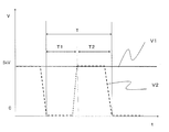
- FIG. 3 shows voltages applied to the discharge electrode 1 and the induction electrode 2 in Example 1.
- V1 indicated by a solid line is an applied voltage to the discharge electrode 1
- V2 indicated by a broken line is an applied voltage to the induction electrode 2.
- a DC voltage of plus 5 kV was applied to the discharge electrode 1, and voltages of 0 kV and plus 5 kV were applied to the induction electrode 2 in the form of pulses.
- T2 the waveform of V2 is slanted when the peak voltage of 5 kV and the bottom voltage of 0 kV are switched. This shows the time lag when the voltage switches.
- T1 the time from when the voltage of the discharge electrode 1 becomes the bottom voltage to the time when the voltage reaches the peak voltage is T1
- T2 is set up to the point in time.
- Example 1 electric field concentration occurs in the discharge electrode 1 during T1, and corona discharge occurs. Among positive ions and negative ions generated by corona discharge, negative ions are neutralized on the discharge electrode 1 and positive ions are repelled from the discharge electrode 1 and released. On the other hand, during the period T2, the voltage difference between both electrodes is small, and the discharge is stopped. That is, the duty D having the time during which ions are generated as a numerator is T1 / T. Table 1 shows the results of measuring the ionic current while changing the duty.
- Example 1 From Table 1, a larger ion current was measured as the duty was smaller. Since the ion current is a relative representation of the number of generated ions, it can be seen that the smaller the duty, the more ions are released to the outside. Here, the mechanism of the ion emission in Example 1 is demonstrated with reference to FIG.
- FIG. 2A schematically shows the state of ion emission during the period T1 shown in FIG.
- a discharge occurs at the discharge electrode 1, and air molecules are decomposed by the discharge to generate positive ions 5 and negative ions.
- the negative ions are neutralized by the discharge electrode 1 and disappear, and the positive ions 5 repel the discharge electrode 1 and are released from the electrode.
- most of the positive ions 5 move toward the induction electrode 2 having a lower resistance than in the air having a higher electrical resistance.
- FIG. 2B shows a state of ion emission during the period T2 shown in FIG.
- the electric potential of the induction electrode 2 becomes comparable with the discharge electrode 1, and discharge stops.
- a large number of positive ions 5 released from the discharge electrode 1 in the period of T1 exist in the vicinity of the discharge electrode 1 and the induction electrode 2.
- a positive voltage is applied to the induction electrode 2 during the period T2. Therefore, the positive ions 5 in the vicinity of the electrode are hardly collected by the electrode due to the repulsive force with the electrode, and the number of ions released into the space increases.
- Example 1 the induction electrode 2 is at the same positive high potential as the discharge electrode 1 during the period T2. Therefore, the positive ions 5 in the vicinity of the induction electrode 2 repel more strongly with the electrode and are effectively released.
- the peak value of the pulse voltage applied to the induction electrode 2 does not need to be the same potential as the voltage of the discharge electrode 1, and may be the same polarity. However, the potential difference between the two electrodes needs to be small enough to stop the discharge. In addition, when the peak voltage of the induction electrode 2 is set to the same potential as or higher than the voltage of the discharge electrode, ions generated more effectively can be discharged into the space by the high potential of the induction electrode 2.
- FIG. 4 shows applied voltages to the discharge electrode 1 and the induction electrode 2 in Comparative Example 1. Both electrodes are the same as in Example 1, and the conditions for measuring the air duct 10 and the ionic current are the same as in Example 1. The other reference numerals are the same as those in the first embodiment.
- a pulse voltage of 0 kV and plus 5 kV was applied to the discharge electrode 1, and a DC voltage of 0 kV was applied to the induction electrode 2.
- ions are generated during the period T1 where the potential difference between the applied voltages to the discharge electrode 1 and the induction electrode 2 is large, and the discharge is stopped during the period T2 where the potential difference is small. Therefore, the duty is T1 / T.
- Table 2 shows the results of measuring the ionic current while changing the duty.
- Example 1 the larger the duty, the larger the ionic current was measured. However, when the duty is increased, the ion current increases, but ozone is likely to be generated. Moreover, when Example 1 and Comparative Example 1 are compared, it can be seen that the amount of ions extracted to the outside is larger in Example 1 as a whole. Further, from Table 2, there was almost no difference in the ionic current when the duty was 0.5 and 0.9. This is considered to indicate that in the case of Comparative Example 1, the emitted ions are saturated when the duty is around 0.5. On the other hand, in Example 1, as shown in Table 1, the ion current increased as the duty decreased. This is a tendency opposite to that in Comparative Example 1, and suggests that the mechanism by which ions are generated and released differs depending on whether the pulse voltage is applied to the discharge electrode or the induction electrode.
- Example 2 Next, with respect to Example 1, the voltage application condition to the induction electrode 2 was varied, and the relationship with the ionic current was investigated. Similarly to Example 1, a DC voltage of 5 kV was applied to the discharge electrode 1, and pulse voltages of 0 kV and 5 kV were applied to the induction electrode 2.
- the ion current was measured under the following conditions: the duty of the pulse voltage was 2, 3, 4, 5, 6, 7, 8, 9, 10, 15, 20, 30, 40%. Further, the frequency of the pulse voltage was changed to 500, 700, 1000, 1500, 2000, 2500, 3000, 4000, 5000 Hz. In particular, parameters not described are the same as those in the first embodiment.
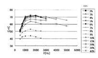
- FIG. 5 is a graph plotting the results, in which the horizontal axis represents the frequency F and the vertical axis represents the ion current I.
- the marker shape represents the duty and corresponds to the value shown in the legend in the figure.
- the ionic current increased under the condition that the duty was small. This is presumably because the non-discharge time is shortened when the duty is large, so that the next discharge occurs before ions existing in the vicinity of the electrode are sufficiently separated from the electrode by the repulsive force of the induction electrode 2. As a result, ions are less likely to be released into the space.
- the duty is preferably 20% or less.
- the ion current is 80% or more of the maximum value under the condition of the same frequency.
- the duty is more preferably 10% or less.
- the ion current is 90% or more of the maximum value under the same frequency condition.
- FIG. 5 the ion current is shown, but the higher the ion current, the more ions are emitted, and the ions are present at a higher concentration in the same space.
- the frequency F is preferably 700 Hz or more.
- the ion current is about 80% of the maximum value under the same duty condition.
- the frequency F is more preferably 1000 Hz or more and 2000 Hz or less.
- the ion current I was the largest under the same duty condition.
- the ion current is almost saturated at a high frequency of 1000 Hz or higher, so that it is not necessary to apply a high frequency pulse. If it is about 1000 Hz to 2000 Hz, the problem of noise due to high frequency can be suppressed.
- the horizontal axis represents T1 which is the discharge time per pulse
- the vertical axis represents T2 which is the non-discharge time per pulse.
- the shape of the marker indicates the magnitude of the ion current, and represents the ion current value shown in the legend in the figure.
- the discharge time T1 is preferably 150 ⁇ s or less
- the non-discharge time T2 is preferably 150 ⁇ s or more and 1500 ⁇ s or less.
- This region is shown as a region A surrounded by a solid line.
- the ion current value is about 80% of the maximum value.
- the non-discharge time T2 is 150 ⁇ s or less
- the time for discharging ions to the space by the repulsive force is shortened, and ions existing in the vicinity of the electrode cannot be sufficiently separated from the electrode.
- the non-discharge time T2 is 1500 ⁇ s or more, the discharge cycle becomes long and the number of discharges decreases, so the amount of ions released per unit time decreases.
- the discharge time T1 is 20 ⁇ s or more and 70 ⁇ s or less
- the non-discharge time T2 is 300 ⁇ s or more and 1000 ⁇ s or less.
- This region is shown as a region B surrounded by a solid line. In the region B, the measured ion current is about 90% of the maximum value, and a higher concentration of ions can be emitted.
- An actual ion generator includes either or both of a positive ion generator and a negative ion generator. More preferably, both a positive ion generator and a negative ion generator are provided, and the sterilization rate is said to increase.
- FIG. 7 is a schematic diagram showing a positive ion generator 7 and a negative ion generator 8 according to the second embodiment.
- corona discharge occurs between the discharge electrode 1 and the induction electrode 2 facing the discharge electrode 1.
- a positive voltage is applied to the discharge electrode 1.
- the negative ions 6 are neutralized by the first electrode, and the positive ions 5 are repelled and released.
- corona discharge is performed between the discharge electrode 1b and the induction electrode 2b facing the discharge electrode 1b.
- a negative voltage is applied to the discharge electrode 1b.
- the positive ions 5 are neutralized by the discharge electrode 1b, and the negative ions 6 are repelled and released. .
- DC power sources 3 and 3b are connected to the discharge electrodes 1 and 1b, respectively, and pulse power sources 4 and 4b are connected to the induction electrodes 2 and 2b, respectively.
- FIG. 8 is a diagram illustrating an example of a voltage application state of the negative ion generator 8 to the discharge electrode 1b and the induction electrode 2b. Since the positive ion generator 7 is the same as that of the first embodiment, the description thereof is omitted.
- V1 represents a voltage applied to the discharge electrode 1b
- V2 represents a voltage applied to the induction electrode 2b.
- a constant voltage of minus 5 kV is applied to the discharge electrode 1b
- pulse voltages of 0 kV and minus 5 kV are applied to the induction electrode 2b.
- a period during which 0 kV which is a bottom value is applied to the induction electrode 2 is defined as T1.
- T1 a period during which 0 kV which is a bottom value is applied to the induction electrode 2 is defined as T2.
- T2 a period during which ⁇ 5 kV which is a peak value is applied to the induction electrode 2 is defined as T2.
- T2 the potential difference between the two electrodes becomes small, and the discharge is stopped. Therefore, the duty with the discharge period as a numerator is T1 / T.
- the potential of the discharge electrode 1 that emits positive ions is preferably +2 kV or more and +10 kV or less. More preferably, it is +3 kV or more and +6 kV or less.
- the distance between the discharge electrode 1 and the induction electrode 2 it is necessary to narrow the distance between the discharge electrode 1 and the induction electrode 2. If the distance between the electrodes becomes too narrow, there is a risk of electric leakage if dust adheres to the discharge electrode 1 and the induction electrode 2 due to static electricity.
- it exceeds +10 kV the generation amount of ozone will increase depending on the shape of the electrode, and the ozone odor may become strong.
- the potential of the discharge electrode 1b that emits negative ions is preferably ⁇ 2 kV to ⁇ 10 kV. More preferably, it is ⁇ 6 kV or more and ⁇ 3 kV or less. In the case of ⁇ 2 kV or more, in order to discharge, it is necessary to reduce the distance between the discharge electrode 1b and the induction electrode 2b, which may cause electric leakage. On the other hand, below -10 kV, the odor of ozone becomes strong, which may cause health problems.
- a DC voltage is applied to the discharge electrodes 1 and 1b and is always maintained at a high potential.
- the discharge electrodes 1 and 1b are at a high potential, so that ions are easily repelled from the discharge electrodes 1 and 1b, and there is an effect that the ions are scattered far away.
- a pulsed voltage that is modulated from the pulse power supply 4 to the positive side is applied to the induction electrode 2
- a pulsed voltage that is modulated from the pulse power supply 4b to the negative side is applied to the induction electrode 2b.
- the peak value of the positive pulse voltage applied to the induction electrode 2 is preferably +10 kV or less, and the pulse amplitude is preferably 15 kV or less.
- the peak of the negative pulse voltage applied to the induction electrode 2b is preferably ⁇ 10 kV or more and the amplitude is 15 kV or less.
- the amount of ozone generated increases depending on the shape of the electrode, which may increase the ozone odor. Further, if the potential difference between the discharge electrode 1 and the induction electrode 2 and the potential difference between the discharge electrode 1b and the induction electrode 2b exceed 15 kV, there is a possibility that arc discharge or streamer discharge may be reached from corona discharge depending on the distance between the electrodes. When arc discharge or streamer discharge occurs, there is a risk that ozone may be generated in an amount that adversely affects health, or the risk of ignition increases.
- the potential difference among the discharge electrode 1, the induction electrode 2, the discharge electrode 1b, and the induction electrode 2b is 6 kV or less. Further, the phase of pulses generated from these two pulse power sources is not particularly limited.
- the distance between the discharge electrode 1 and the induction electrode 2 and the distance between the discharge electrode 1b and the induction electrode 2b are 2 mm or more.
- the upper limit of the interelectrode distance is not particularly limited, but is preferably less than 100 mm. If the distance between the electrodes is large, not only will the discharge start voltage increase and the amount of ozone generated will increase, but it will not discharge to the counter electrode, but may discharge to the substrate or housing, leading to equipment failure. .
- the present invention relates to an ion generator that discharges ions in the air and discharges them into the space, and an electric device equipped with the same.
- an electric device equipped with the same.
- the above-mentioned electric equipment for example, it is mainly used in a closed space (inside a house, one room in a building, a hospital room or operating room, a car, an airplane, a ship, a warehouse, a refrigerator, etc.) It can be widely applied to air conditioners, dehumidifiers, humidifiers, air purifiers, refrigerators, fan heaters, microwave ovens, washing / drying machines, vacuum cleaners, sterilizers, and the like.
Landscapes
- Disinfection, Sterilisation Or Deodorisation Of Air (AREA)
Abstract
放電により発生したイオンを、効率的に空間に放出するイオン発生装置および、イオン発生方法を実現する。本発明に係るイオン発生装置は、放電電極(1,1b)と、放電電極(1,1b)に対向する誘導電極(2,2b)を有するものであり、放電電極(1,1b)に直流電圧を印加する直流電源(3,3b)と、誘導電極(2,2b)に放電電極(1,1b)との間で放電が起こる第1の電圧と、放電が停止する第2の電圧を印加するパルス電源(4,4b)とを備えている。また、第2の電圧は、放電電極(1,1b)に印加する直流電圧と同極性であることを特徴としている。
Description
本発明は、空気中で放電してイオンを空間に放出するイオン発生装置、及びこれを備えた電気機器に関する。
イオン発生装置は、放電電極および誘導電極間に電圧を印加し、放電電極でコロナ放電を生じさせることで、正イオンあるいは負イオンを発生させる。市販されているイオン発生装置は大きく分けて2種類あり、負イオンだけを発生させるものと、正イオンと負イオンの両方を発生させるものがある。負イオンだけ発生させるイオン発生装置は、リラックス効果があるとされ、正イオンと負イオンを両方発生させる装置は、空気中に浮遊するカビ菌やウイルスの分解、におい成分の分解、静電気の除去等の効果があるとされる。また、このような効果は、発生させるイオン量が多いほど一層高められる。
特開2007-305321号公報(特許文献1)には、放電電極と、誘導電極を有するイオン発生素子が記載されている。誘導電極は、金属板からなっており、放電電極に対応した位置に貫通孔を有している。放電電極は、針状の形状であり、その先端が誘導電極の貫通孔の中心に位置するように、配置されている。この放電電極と誘導電極の間に高電圧が印加されることによって、コロナ放電が生じ、イオンが発生する。ここで、放電電極にプラスの電位が印加された場合、発生した正イオンと負イオンのうち、負イオンは放電電極上で中和され、正イオンは反発して放出される。また、放電電極にマイナスの電位が印加された場合、発生した正イオンと負イオンのうち、正イオンは放電電極上で中和され、負イオンは反発して放出される。
特開2004-363088号公報(特許文献2)には、図9で示すように、放電電極と誘導電極の両電極にプラス、または、両電極にマイナスのパルス電圧を印加して放電することが記載されている。図9(a)は、誘導電極に印加される電圧、(b)は、放電電極に印加される電圧を示す。ここで、両電極に電圧が印加されているT1の期間は、放電が起こり、イオンが発生する。一方、両電極に電圧が印加されていないT2の期間は、放電が停止している。
イオン発生装置においては、空間に効率的にイオンを放出するため、送風によりイオンを風に乗せて空間に拡散させることが一般的である。
しかしながら、誘導電極が接地されている場合、放電電極で発生したイオンは、両電極間の電界によって、電気的に抵抗の大きい空気中ではなく、誘導電極に移動してしまう。そのため、送風により空間に拡散する前に、発生したイオンの大半が、誘導電極に回収されてしまうという課題があった。
また、特開2004-363088号公報(特許文献2)のように、放電時に放電電極と誘導電極の両電極にプラス、または、両電極にマイナスの電圧を印加した場合、放電電極で発生したイオンは、誘導電極の電位と反発し、誘導電極に回収されにくくなることが期待される。しかしながら、放電が終了すると誘導電極の電位は0となり、電極近傍に存在するイオンが、同様に誘導電極に回収されてしまう。
本発明は、従来技術における上記の問題に鑑みてなされたものであり、その目的は、発生したイオンが放電電極およびに誘導電極に回収されることを抑制することで、従来よりも高濃度のイオンを発生する装置ならびに方法を提供することである。
本発明に係るイオン発生装置は、放電電極と、放電電極に対向する誘導電極を有するものであり、放電電極に直流電圧を印加する直流電源と、誘導電極に放電電極との間で放電が起こる第1の電圧と、放電が停止する第2の電圧を印加するパルス電源とを備えている。また、第2の電圧は、放電電極に印加する直流電圧と同極性であることを特徴としている。
また、第2の電圧の絶対値は、放電電極に印加する直流電圧の絶対値の2分の1より大きい値であることが好ましい。
また、第2の電圧は、前記放電電極に印加する直流電圧と略同電圧であることが好ましい。
また、パルス電源のデューティは、0.2以下であることが好ましい。
また、パルス電源の周波数は、700Hz以上であることが好ましい。
また、パルス電源の周波数は、700Hz以上であることが好ましい。
また、1周期あたりの放電時間は、150μs以下であることが好ましい。
また、1周期あたりの非放電時間は、150μs以上かつ、1500μs以下であることが好ましい。
また、1周期あたりの非放電時間は、150μs以上かつ、1500μs以下であることが好ましい。
また、本発明に係るイオン発生方法は、放電電極と、放電電極に対向する誘導電極を用いるイオン発生方法であって、放電電極に直流電圧を印加し、誘導電極に放電電極との間で放電が起こる第1の電圧と、放電が停止する第2の電圧を印加し、第2の電圧は、放電電極に印加する直流電圧と同極性とすることを特徴としている。
本発明に係る、イオン発生装置およびイオン発生方法によれば、発生したイオンが放電電極および誘導電極に回収されることを抑制することができ、従来よりも高濃度のイオンを発生する装置ならびに方法を提供することができる。
(第1の実施形態)
本発明の一実施形態について、図面を参照して詳細に説明する。図1は、イオン発生装置の模式図である。図2は、イオン発生装置の動作原理を示す模式図である。
本発明の一実施形態について、図面を参照して詳細に説明する。図1は、イオン発生装置の模式図である。図2は、イオン発生装置の動作原理を示す模式図である。
図1、2において、第1の実施形態に係るイオン発生装置は、主として、放電電極1と、放電電極1に対向する誘導電極2と、放電電極1に接続された直流電源3と、誘導電極2に接続されたパルス電源4と、放電電極1および誘導電極2が支持されている基板11と、これらの周囲にある風路管10とで構成されている。発生したイオンは風路管10内を通過して外へ放出される。
放電電極1は、例えば、針状、鋸歯状、ワイヤー状などの先端を有した形状であり、本実施形態では、針状電極としている。誘導電極2は、例えば、平板状、リング状などの形状で放電電極1より大きい表面積を有しており、放電電極1を取り囲むように配置されている。また、基板11は、絶縁材料からなり、放電電極1と誘導電極2が設置され、風路管10と絶縁されている。
風路管10は、例えば一端に、開口9を有しており、発生したイオンがそこから部屋空間に放出される。また、風路管10の開口9と対向する側には、図示しない送風機が設けられ、発生したイオンは、送風機による風に乗って、風路を通過し、部屋空間に拡散される。また、風路管10の材質は、特に限定されることはなく、成形性に優れた樹脂や、金属などから形成される。
次に、放電電極1と誘導電極2への電圧の印加状態とイオンの発生量の関係について説明する。
(実施例1)
図1及び図2を参照すると、放電電極1は、先端が尖った半径10μmの針状電極を用い、誘導電極2は、内径が9mmのリング状電極を用いた。また、風路管10は、50mm角の断面をもつものを用い、第1、第2の電極に対して十分大きいものとした。そして、両電極から10cm離れた位置にイオンカウンタを置いてイオン電流を測定した。
(実施例1)
図1及び図2を参照すると、放電電極1は、先端が尖った半径10μmの針状電極を用い、誘導電極2は、内径が9mmのリング状電極を用いた。また、風路管10は、50mm角の断面をもつものを用い、第1、第2の電極に対して十分大きいものとした。そして、両電極から10cm離れた位置にイオンカウンタを置いてイオン電流を測定した。
図3は、実施例1における、放電電極1と誘導電極2への印加電圧である。実線で示したV1は、放電電極1への印加電圧、破線で示したV2は、誘導電極2への印加電圧である。放電電極1にプラス5kVの直流電圧を印加し、誘導電極2に0kVとプラス5kVの電圧をパルス状に印加した。
図3において、誘導電極2に印加されるV2は、一周期をT(=T1+T2)とする。ここで、図3より、V2は、ピーク電圧である5kVとボトム電圧である0kVが切り替わるとき波形が斜めになっている。これは、電圧が切り替わるときのタイムラグを示す。本実施例では、放電電極1の電圧が、ボトム電圧になった時点から、ピーク電圧になった時点までを、T1とし、放電電極1の電圧が、ピーク電圧になった時点から、ボトム電圧になった時点までを、T2としている。
実施例1において、T1の期間、放電電極1に電界集中が発生しコロナ放電が起こる。コロナ放電によって発生した正イオンと負イオンのうち、負イオンは、放電電極1上で中和し、正イオンは、放電電極1と反発して放出される。一方、T2の期間、両電極間の電圧差は小さくなっており、放電は停止している。すなわち、イオンが発生している時間を分子とするデューティDは、T1/Tとなる。表1に、デューティを変化させてイオン電流を測定した結果を示す。

表1より、デューティが小さいときほど大きなイオン電流が計測された。イオン電流は、発生しているイオンの個数を相対的に表したものであるから、デューティが小さいときほど多数のイオンが外部へ放出されていることがわかる。ここで、実施例1におけるイオン放出のメカニズムを図2を参照して説明する。
図2(a)は、図3に示すT1の期間におけるイオン放出の様子を模式的に示している。図2(a)において、放電電極1で放電が起こっており、放電により空気分子が分解され正イオン5と負イオンが発生する。発生したイオンの内、負イオンは、放電電極1で中和されて消滅し、正イオン5は、放電電極1と反発し電極から放出される。しかし、正イオン5の大部分は、電気的に抵抗の大きい空気中よりも、抵抗の小さい誘導電極2に向かって移動する。
図2(b)は、図3に示すT2の期間におけるイオン放出の様子を表している。図2(b)において、誘導電極2の電位が放電電極1と同程度になり、放電が停止する。しかし、放電が停止しても、T1の期間に放電電極1から放出された正イオン5は、放電電極1と誘導電極2の近傍に多数存在していると考えられる。ここで、実施例1では、T2の期間、誘導電極2にはプラスの電圧が印加されている。そのため、電極近傍の正イオン5は、電極との反発力により、電極に回収されにくくなり、空間に放出されるイオンが増加することになる。
また、実施例1において、T2の期間、誘導電極2は、放電電極1と同じプラスの高電位となっている。そのため、誘導電極2近傍の正イオン5は、電極とより強く反発し、効果的に放出される。
以上のように、誘導電極2に印加されるパルス電圧のピーク値は、放電電極1の電圧と同電位である必要はなく、同極性であればよい。ただし、両電極間の電位差は、放電が停止する程度に小さくなっている必要はある。また、誘導電極2のピーク電圧を、放電電極の電圧と同電位、または、それ以上とした場合、誘導電極2の高電位によって、より効果的に発生したイオンを空間に放出することができる。
また、実験では、誘導電極2のピーク電圧と、放電電極の電圧が略同電位のとき、放出されるイオンが特に多くなった。また、その場合、電圧の種類が少なくてすむため、駆動回路もシンプルで低コスト化が可能である。
(比較例1)
図4は、比較例1における、放電電極1と誘導電極2への印加電圧である。両電極は、実施例1と同じものを用い、風路管10およびイオン電流の測定条件は、実施例1と同一条件とする。その他、同じ符号は実施例1と同様とする。
(比較例1)
図4は、比較例1における、放電電極1と誘導電極2への印加電圧である。両電極は、実施例1と同じものを用い、風路管10およびイオン電流の測定条件は、実施例1と同一条件とする。その他、同じ符号は実施例1と同様とする。
図4に示すように、放電電極1に0kVとプラス5kVのパルス電圧を印加し、誘導電極2に0kVの直流電圧を印加した。比較例1では、放電電極1と誘導電極2への印加電圧の電位差の大きいT1の期間にイオンが発生し、電位差が小さいT2の期間は、放電が停止している。したがって、デューティはT1/Tとなる。表2に、デューティを変化させてイオン電流を測定した結果を示す。

表2より、デューティが大きいほど大きなイオン電流が計測された。ただし、デューティを大きくするとイオン電流は大きくなるが、オゾンが発生しやすくなる。また、実施例1と比較例1を比較すると、全体的に実施例1の方が、外部へ取り出されるイオン量が大きいことがわかる。また、表2より、デューティが0.5と0.9の条件では、イオン電流に、ほとんど差は見られなかった。これは、比較例1の場合、デューティが0.5付近で、放出されるイオンが飽和状態になったことを示していると考えられる。一方、実施例1では、表1で示したように、デューティが小さいほど、イオン電流は大きくなった。これは、比較例1の場合と逆の傾向であり、パルス電圧を放電電極か誘導電極のどちらに印加するかによって、イオンが発生し放出されるメカニズムが違うことを示唆するものである。
比較例1における、放電について説明する。図4において、T1の期間、放電によって正イオンが発生している。発生した正イオンは、送風に乗って、空間に放出されるが、放電電極1および誘導電極2の近傍にも多数のイオンが存在している。T1の期間が終了すると、放電電極1と誘導電極の電圧は、共に0Vとなる。このとき、いまだ、電極近傍に存在している正イオンは、その大部分が第2の電極に移動して回収されてしまう。ここで、周囲の空間と両電極はともに0Vであるが、空気はほぼ絶縁性であるのに対し、電極は導電性であるため、正イオンは、電極に移動し回収されてしまう。そのため、表1と2において、比較例1では、実施例1よりもイオン電流が小さくなっている。
また、先行文献2では、放電期間中、放電電極と誘導電極の両電極ともにプラス、または両電極ともにマイナスの電圧を印加している。しかし、非放電期間については、考慮されておらず、比較例1の場合と同様に、放電が終了したときに、電極近傍のイオンが電極に回収されてしまうことが考えられる。
(実施例2)
次に、実施例1に対して、誘導電極2への電圧印加条件を変動させて、イオン電流との関係を調査した。実施例1と同様に、放電電極1には、5kVの直流電圧を印加し、誘導電極2には、0kVと5kVのパルス電圧を印加した。パルス電圧の、デューティは、2、3、4、5、6、7、8、9、10、15、20、30、40%の各条件でイオン電流を測定した。また、パルス電圧の周波数を、500、700、1000、1500、2000、2500、3000、4000、5000Hzと変動させた。なお、特に、記載しないパラメータは上記実施例1と同じとする。
(実施例2)
次に、実施例1に対して、誘導電極2への電圧印加条件を変動させて、イオン電流との関係を調査した。実施例1と同様に、放電電極1には、5kVの直流電圧を印加し、誘導電極2には、0kVと5kVのパルス電圧を印加した。パルス電圧の、デューティは、2、3、4、5、6、7、8、9、10、15、20、30、40%の各条件でイオン電流を測定した。また、パルス電圧の周波数を、500、700、1000、1500、2000、2500、3000、4000、5000Hzと変動させた。なお、特に、記載しないパラメータは上記実施例1と同じとする。
図5は、その結果をプロットしたグラフであり、横軸が周波数F、縦軸がイオン電流Iを示す。また、マーカの形状は、デューティを表しており、図中の凡例に示した値と対応する。
図5に示されるように、デューティが小さい条件でイオン電流は大きくなった。これは、デューティが大きい場合、非放電時間が短くなるので、電極近傍に存在するイオンが、誘導電極2の反発力によって、電極から十分に離れる前に、次の放電が起こるためと考えられる。そのため、イオンが空間に放出されにくくなる。
ここで、デューティは、20%以下であることが好ましい。デューティが、20%以下の条件で、イオン電流は、同じ周波数の条件での最大値の80%以上となっている。また、デューティは、10%以下であることがさらに好ましい。デューティが、10%以下の条件で、イオン電流は、同じ周波数の条件での最大値の90%以上となっている。なお、図5では、イオン電流で示しているがイオン電流が高いほど放出されるイオン数が多くなり、同じ空間内においてイオンが高濃度で存在することになる。
また、図5より、周波数が小さい条件では、イオン電流が小さいことがわかる。これは、周波数Fが小さいと、放電回数が少なくなり、イオンの発生量が減少したと考えられる。
ここで、周波数Fは、700Hz以上であることが好ましい。周波数が、700Hz以上の条件で、イオン電流は、同じデューティの条件での最大値の80%程度となっている。また、周波数Fは、1000Hz以上かつ2000Hz以下であることがさらに好ましい。周波数Fが、1000Hz以上かつ2000Hz以下であるとき、イオン電流Iは、同じデューティの条件では、もっとも大きくなった。図から明らかなように1000Hz以上の高周波でイオン電流はほぼ飽和するため、あまり高周波パルスを印加する必要はない。1000Hzから2000Hz程度であれば、高周波によるノイズの問題を抑制することができる。また、高周波になっても、ストリーマ放電に発展しないことが望ましい。ストリーマ放電になることで、電子温度が高くなり、解離反応が主反応となるためオゾン濃度が増加する。
次に、放電時間と、非放電時間が、イオン電流に与える影響について、図6に示す。図6において、横軸が1パルスあたりの放電時間であるT1、縦軸が1パルスあたりの非放電時間であるT2を示す。また、図6において、マーカの形状は、イオン電流の大きさを示しており、図中の凡例に示したイオン電流値を表す。
図6において、放電時間T1は、150μs以下で、非放電時間T2は、150μs以上かつ1500μs以下であることが好ましい。この領域を領域Aとして、実線で囲んで示す。領域Aでは、イオン電流値は、最大値の80%程度となっている。ここで、放電時間T1をそれ以上長くしても、発生したイオンの大部分は、誘導電極2に回収されて空間に放出されない。また、非放電時間T2が、150μs以下であると、反発力によってイオンを空間に放出する時間が短くなり、電極近傍に存在するイオンが、電極から十分に離れることができない。また、非放電時間T2が、1500μs以上であると、放電の周期が長くなり、放電回数が少なくなるため、単位時間あたりに放出されるイオンの量は少なくなる。
また、図6において、放電時間T1が20μs以上70μs以下で、非放電時間T2が300μs以上かつ1000μs以下であることがさらに好ましい。この領域を領域Bとして実線で囲んで示す。領域Bでは、測定されたイオン電流は、最大値の90%程度であり、より高濃度のイオンを放出することができる。
また、図5、6において、各放電条件は、適宜、組み合わせることが可能である。最適な条件を組みあわせることで、放出されるイオンの更なる高濃度化が期待される。
(第2の実施形態)
実際のイオン発生装置は、正イオン発生装置と、負イオン発生装置のいずれか、もしくは両方を具備している。正イオン発生装置、負イオン発生装置の両方が具備されていることがより好ましく、除菌速度が増加すると言われている。
(第2の実施形態)
実際のイオン発生装置は、正イオン発生装置と、負イオン発生装置のいずれか、もしくは両方を具備している。正イオン発生装置、負イオン発生装置の両方が具備されていることがより好ましく、除菌速度が増加すると言われている。
図7は、第2の実施形態にかかる、正イオン発生装置7と、負イオン発生装置8を示す概略図である。
正イオン発生装置7では、放電電極1と、放電電極1に対向する誘導電極2との間でコロナ放電が起こる。放電電極1には、プラスの電圧が印加されており、発生した正イオン5と負イオン6のうち、負イオン6は、第1の電極で中和され、正イオン5は反発して放出される。
負イオン発生装置8側では、放電電極1bと、放電電極1bに対向する誘導電極2bとの間でコロナ放電させる。放電電極1bには、マイナスの電圧が印加されており、発生した正イオン5と負イオン6のうち、正イオン5は、放電電極1bで中和され、負イオン6は反発して放出される。
なお、本実施形態においては、誘導電極2および2bとして、リング状の電極を用いた場合を示しており、図7の2および2bは、リングの断面を表している。また、放電電極1と1bには、それぞれ、直流電源3と3bが接続され、誘導電極2と2bには、それぞれ、パルス電源4と4bが接続される。
次に、負イオン発生装置8の各電極に印加する電圧波形について説明する。図8は、負イオン発生装置8の、放電電極1bと、誘導電極2bへの電圧印加状態の一例を示す図である。正イオン発生装置7については、実施例1の場合と同様であるため説明を省略する。
図8において、V1は、放電電極1bに印加する電圧、V2は、誘導電極2bに印加する電圧を示す。放電電極1bには、マイナス5kVの定電圧が印加され、誘導電極2bには、0kVとマイナス5kVのパルス電圧が印加される。V2の周期はT(=T1+T2)とする。
図8において、誘導電極2にボトム値である0kVを印加している期間をT1とする。T1の期間、両電極間の電位差は大きく、コロナ放電によって、イオンが発生している。一方、誘導電極2にピーク値である-5kVが印加されている期間をT2とする。T2の期間、両電極間の電位差は小さくなり、放電は停止している。したがって、放電している期間を分子とするデューティは、T1/Tとなる。
発生した負イオンがゼロ電位の室内に向けて放出されるのは、正イオンの場合と同様に説明される。放電時間T1が終了すると、誘導電極2bの電位が放電電極1bと同程度になり、放電が停止する。ここで、放電電極1bの近傍には、多数の負イオンが存在している。しかし、電極近傍のイオンは、誘導電極2bの電位がマイナスになっているため、誘導電極2に回収されにくくなる。そのため、負イオンは、近傍のゼロ電位に近い方向に向かうため、ゼロ電位に近い部屋空間に放出されやすくなる。
本発明に係るイオン発生装置において、正イオンを放出する放電電極1の電位は、+2kV以上+10kV以下であることが好ましい。より好ましくは+3kV以上+6kV以下である。+2kV以下では放電開始させるためには、放電電極1と誘導電極2間の電極間距離を狭くする必要がある。電極間距離が狭くなりすぎると、放電電極1と誘導電極2に静電気で埃が付着した場合、漏電のおそれがある。また、+10kVを超えると、電極の形状によってはオゾンの発生量が増え、オゾン臭が強くなる恐れが生じる。
また、同様に、負イオンを放出する放電電極1bの電位は、-2kVから-10kVであることが好ましい。より好ましくは-6kV以上-3kV以下である。-2kV以上の場合、放電させるには、放電電極1bと誘導電極2bの電極間距離が狭くする必要があり、漏電するおそれがある。また、-10kVを下回ると、オゾン臭が強くなり、健康を害する恐れが生じる。
また、本発明に係るイオン発生装置においては、放電電極1、1bに直流電圧が印加され、常に高電位に維持されている。このように、放電が停止した後も、放電電極1、1bが高電位であることにより、イオンを放電電極1、1bから反発させやすくなり、遠方に飛散させる効果がある。
また、誘導電極2には、パルス電源4から正側に変調するパルス状の電圧が印加されており、誘導電極2bにはパルス電源4bから負側に変調するパルス状の電圧が印加されている。誘導電極2に印加する正側のパルス状の電圧のピーク値は、+10kV以下で、パルスの振幅は15kV以下であることが好ましい。また、誘導電極2bに印加する負側のパルス状の電圧のピークは、-10kV以上で、振幅が15kV以下であることが好ましい。
最小ピークが-10kV、最大ピークが+10kVを上回ると、電極の形状によってはオゾンの発生量が増え、オゾン臭が強くなる恐れが生じる。また放電電極1と誘導電極2の電位差および放電電極1bと誘導電極2bの電位差が15kVを超えると、電極間距離によってはコロナ放電からアーク放電やストリーマ放電に達する恐れがある。アーク放電やストリーマ放電になると、健康に悪影響を及ぼす量のオゾンが発生する恐れが生じたり、発火の危険性が増大したりする。オゾン発生量を減少させるには、放電電極1、誘導電極2および放電電極1b、誘導電極2bの電位差はそれぞれ6kV以下であることが、より好ましい。また、これら2つのパルス電源から発生するパルスの位相は特に制限されない。
本発明に係るイオン発生装置は、放電電極1と誘導電極2との電極間距離、および、放電電極1bと誘導電極2bとの電極間距離は2mm以上である。
電極間距離が2mm以下であると、静電気で埃が付着した場合、漏電しやすくなる。また、電極間距離の上限は特に制限されないが、100mmを下回ることが好ましい。電極間距離が大きい場合、放電開始電圧が高くなりオゾン発生量が増加するだけでなく、対向電極に対して放電せず、基板や筐体に対して放電することがあり、機器の故障につながる。
本発明は、空気中で放電してイオンを空間に放出するイオン発生装置、及びこれを備えた電気機器に関するものである。なお、上記の電気機器としては、例えば、主に閉空間(家屋内、ビル内の一室、病院の病室や手術室、車内、飛行機内、船内、倉庫内、冷蔵庫の庫内等)で使用される空気調和機、除湿器、加湿器、空気清浄機、冷蔵庫、ファンヒータ、電子レンジ、洗濯乾燥機、掃除機、殺菌装置などに広く適用することができる。
1,1b 第1の電極、 2,2b 第2の電極、 3,3b 直流電源、 4,4b パルス電源、 5 正イオン、 6 負イオン、 7 正イオン発生装置、 8 負イオン発生装置、 9 開口、 10 風路管、 11 基板。
Claims (8)
- 放電電極(1,1b)と、前記放電電極(1,1b)に対向する誘導電極(2,2b)を有するイオン発生装置において、
前記放電電極(1,1b)に直流電圧を印加する直流電源(3,3b)と、
前記誘導電極(2,2b)に前記放電電極との間で放電が起こる第1の電圧と、放電が停止する第2の電圧を印加するパルス電源(4,4b)と、を備え、
前記第2の電圧は、前記放電電極(1,1b)に印加する直流電圧と同極性であるイオン発生装置。 - 前記第2の電圧の絶対値は、前記放電電極(1,1b)に印加する直流電圧の絶対値の2分の1より大きい値である請求項1に記載のイオン発生装置。
- 前記第2の電圧は、前記放電電極(1,1b)に印加する直流電圧と略同電圧である請求項1に記載のイオン発生装置。
- 前記パルス電源(4,4b)のデューティ(D)は、0.2以下である請求項1に記載のイオン発生装置。
- 前記パルス電源(4,4b)の周波数(F)は、700Hz以上である請求項1に記載のイオン発生装置。
- 1周期あたりの放電時間(T1)は、150μs以下である請求項1に記載のイオン発生装置。
- 1周期あたりの非放電時間(T2)は、150μs以上かつ1500μs以下である請求項1に記載のイオン発生装置。
- 放電電極(1,1b)と、前記放電電極(1,1b)に対向する誘導電極(2,2b)を用いるイオン発生方法において、
前記放電電極(1,1b)に直流電圧を印加し、
前記誘導電極(2,2b)に前記放電電極(1,1b)との間で放電が起こる第1の電圧と、放電が停止する第2の電圧を印加し、
前記第2の電圧は、前記放電電極(1,1b)に印加する直流電圧と同極性とするイオン発生方法。
Applications Claiming Priority (2)
| Application Number | Priority Date | Filing Date | Title |
|---|---|---|---|
| JP2011135857A JP5053450B1 (ja) | 2011-06-20 | 2011-06-20 | イオン発生装置およびイオン発生方法 |
| JP2011-135857 | 2011-06-20 |
Publications (1)
| Publication Number | Publication Date |
|---|---|
| WO2012176524A1 true WO2012176524A1 (ja) | 2012-12-27 |
Family
ID=47189502
Family Applications (1)
| Application Number | Title | Priority Date | Filing Date |
|---|---|---|---|
| PCT/JP2012/058871 Ceased WO2012176524A1 (ja) | 2011-06-20 | 2012-04-02 | イオン発生装置およびイオン発生方法 |
Country Status (2)
| Country | Link |
|---|---|
| JP (1) | JP5053450B1 (ja) |
| WO (1) | WO2012176524A1 (ja) |
Families Citing this family (2)
| Publication number | Priority date | Publication date | Assignee | Title |
|---|---|---|---|---|
| JP5817776B2 (ja) * | 2013-04-17 | 2015-11-18 | 三菱電機株式会社 | 電界生成装置及びこれを備えた空気調和機、空気清浄機、送風機 |
| JP2015077558A (ja) * | 2013-10-17 | 2015-04-23 | パナソニックIpマネジメント株式会社 | 有効成分発生装置 |
Citations (4)
| Publication number | Priority date | Publication date | Assignee | Title |
|---|---|---|---|---|
| JPS61151570A (ja) * | 1984-12-26 | 1986-07-10 | Canon Inc | 放電装置 |
| JP2001042598A (ja) * | 1999-07-28 | 2001-02-16 | Ricoh Co Ltd | イオン発生装置及び画像形成装置 |
| JP2006047641A (ja) * | 2004-08-04 | 2006-02-16 | Matsushita Electric Ind Co Ltd | イオン発生装置およびイオン発生装置を有する画像形成装置 |
| JP2010187766A (ja) * | 2009-02-16 | 2010-09-02 | Panasonic Electric Works Co Ltd | イオン発生装置及び美容装置 |
Family Cites Families (1)
| Publication number | Priority date | Publication date | Assignee | Title |
|---|---|---|---|---|
| JP4063784B2 (ja) * | 2003-05-15 | 2008-03-19 | シャープ株式会社 | イオン発生素子、イオン発生装置 |
-
2011
- 2011-06-20 JP JP2011135857A patent/JP5053450B1/ja not_active Expired - Fee Related
-
2012
- 2012-04-02 WO PCT/JP2012/058871 patent/WO2012176524A1/ja not_active Ceased
Patent Citations (4)
| Publication number | Priority date | Publication date | Assignee | Title |
|---|---|---|---|---|
| JPS61151570A (ja) * | 1984-12-26 | 1986-07-10 | Canon Inc | 放電装置 |
| JP2001042598A (ja) * | 1999-07-28 | 2001-02-16 | Ricoh Co Ltd | イオン発生装置及び画像形成装置 |
| JP2006047641A (ja) * | 2004-08-04 | 2006-02-16 | Matsushita Electric Ind Co Ltd | イオン発生装置およびイオン発生装置を有する画像形成装置 |
| JP2010187766A (ja) * | 2009-02-16 | 2010-09-02 | Panasonic Electric Works Co Ltd | イオン発生装置及び美容装置 |
Also Published As
| Publication number | Publication date |
|---|---|
| JP5053450B1 (ja) | 2012-10-17 |
| JP2013004384A (ja) | 2013-01-07 |
Similar Documents
| Publication | Publication Date | Title |
|---|---|---|
| JP6185497B2 (ja) | コロナ放電を制御する方法 | |
| US10766039B2 (en) | Electrostatic precipitator | |
| JPWO2012063856A1 (ja) | プラズマ発生装置、プラズマ発生方法及びオゾン発生抑制方法 | |
| CN103857167B (zh) | 等离子体发生装置 | |
| WO2018207385A1 (ja) | 放電装置および電気機器 | |
| JP5053450B1 (ja) | イオン発生装置およびイオン発生方法 | |
| US7214949B2 (en) | Ion generation by the temporal control of gaseous dielectric breakdown | |
| JP4624289B2 (ja) | イオン発生装置および空気調和機 | |
| JP2007294180A (ja) | イオン発生装置及びこれを備えた電気機器 | |
| WO2013121669A1 (ja) | イオン発生素子及びそれを備えたイオン発生装置 | |
| WO2013027485A1 (ja) | イオン発生装置及びこれを備えた空気清浄装置 | |
| KR20090009928A (ko) | 이온 발생장치 | |
| JP2014107202A (ja) | イオン発生装置及び電気機器 | |
| JP2014121424A (ja) | 放電ユニットおよびこれを用いた空気清浄装置 | |
| JP5303020B2 (ja) | イオン発生装置及び空気清浄装置 | |
| JP2005116229A (ja) | イオン発生装置及びこれを備えた電気機器 | |
| JP2011129351A (ja) | 交流高電圧放射式除電装置 | |
| JP2013004385A (ja) | イオン発生装置及び電気機器 | |
| JP2017224589A (ja) | イオン発生装置 | |
| JP2004349145A (ja) | イオン発生装置及びこれを備えた電気機器 | |
| KR100518469B1 (ko) | 직류용 음이온 및 은이온 발생기 | |
| JP5291772B2 (ja) | イオン発生装置及び電気機器 | |
| JP2014022338A (ja) | イオン発生装置 | |
| JP2013165034A (ja) | イオン発生装置 | |
| JP2014108315A (ja) | 微生物不活化デバイス |
Legal Events
| Date | Code | Title | Description |
|---|---|---|---|
| 121 | Ep: the epo has been informed by wipo that ep was designated in this application |
Ref document number: 12802692 Country of ref document: EP Kind code of ref document: A1 |
|
| NENP | Non-entry into the national phase |
Ref country code: DE |
|
| 122 | Ep: pct application non-entry in european phase |
Ref document number: 12802692 Country of ref document: EP Kind code of ref document: A1 |