WO2012169556A1 - 蓋体のリンク構造 - Google Patents
蓋体のリンク構造 Download PDFInfo
- Publication number
- WO2012169556A1 WO2012169556A1 PCT/JP2012/064602 JP2012064602W WO2012169556A1 WO 2012169556 A1 WO2012169556 A1 WO 2012169556A1 JP 2012064602 W JP2012064602 W JP 2012064602W WO 2012169556 A1 WO2012169556 A1 WO 2012169556A1
- Authority
- WO
- WIPO (PCT)
- Prior art keywords
- lid
- shaft
- link
- main body
- arm
- Prior art date
- Legal status (The legal status is an assumption and is not a legal conclusion. Google has not performed a legal analysis and makes no representation as to the accuracy of the status listed.)
- Ceased
Links
Images













Classifications
-
- B—PERFORMING OPERATIONS; TRANSPORTING
- B60—VEHICLES IN GENERAL
- B60R—VEHICLES, VEHICLE FITTINGS, OR VEHICLE PARTS, NOT OTHERWISE PROVIDED FOR
- B60R11/00—Arrangements for holding or mounting articles, not otherwise provided for
- B60R11/02—Arrangements for holding or mounting articles, not otherwise provided for for radio sets, television sets, telephones, or the like; Arrangement of controls thereof
- B60R11/0229—Arrangements for holding or mounting articles, not otherwise provided for for radio sets, television sets, telephones, or the like; Arrangement of controls thereof for displays, e.g. cathodic tubes
- B60R11/0235—Arrangements for holding or mounting articles, not otherwise provided for for radio sets, television sets, telephones, or the like; Arrangement of controls thereof for displays, e.g. cathodic tubes of flat type, e.g. LCD
-
- B—PERFORMING OPERATIONS; TRANSPORTING
- B60—VEHICLES IN GENERAL
- B60R—VEHICLES, VEHICLE FITTINGS, OR VEHICLE PARTS, NOT OTHERWISE PROVIDED FOR
- B60R11/00—Arrangements for holding or mounting articles, not otherwise provided for
- B60R2011/0042—Arrangements for holding or mounting articles, not otherwise provided for characterised by mounting means
- B60R2011/008—Adjustable or movable supports
- B60R2011/0082—Adjustable or movable supports collapsible, e.g. for storing after use
Definitions
- the present invention relates to a link structure of a lid, so that when the first lid of one of the two lids is pressed to release the lock-like body of the lock mechanism, the other second lid does not move. By doing so, interference between both lids can be prevented.
- the lid is pressed between the back surface of the lid and the opening end surface of the opening of the main body facing the back surface with the lid closed.
- a gap for operation is required, there is a problem that the back surface of the lid and the opening end surface on the main body side easily interfere with each other.
- the rear surface of the lid interferes with the opening end surface on the main body side, a sufficient pressing operation cannot be performed, and the unlocked state of the lock structure is uncertain, which is likely to cause an operation failure.
- the gap between the back surface of the lid and the opening end surface on the main body side is widened, there is a problem that the appearance is deteriorated.
- the present invention has been made in view of the above-described problems of the prior art, and the object of the present invention is interference between both lids, interference between the lid and the main body, and those. It is intended to reduce the operation failure caused by the cause.
- the present invention has been made to achieve the above object, and the present invention is characterized by the following points.
- the link structure (for example, link mechanism) of a cover body is equipped with the following structure.
- Main body The main body is a hollow body having an opening on the upper surface.
- Lid The lid is pivotally fixed to the main body and opens and closes the opening of the main body.
- the lid has an arm portion (for example, first and second arm portions) located at one end, and the arm portions (for example, first and second arm portions) face the opening of the main body.
- Each of the two side lids (for example, a first lid and a second lid) is fixed to each of the opposite side surfaces, and the other free end of the other end faces each other on the opening of the main body.
- one of the first lids is provided with a lock mechanism that can be unlocked by pressing the first lid.
- the other second lid is connected to the first lid via a link (for example, the second link) capable of transmitting a rotational force.
- one end of the link (for example, the second link) is pivoted to the arm portion (for example, the first arm portion) of the first lid.
- the link for example, the second link
- the arm portion for example, the second arm portion
- the shaft for example, the movable shaft
- the hole for example, the connecting hole
- a clearance for example, a large-diameter portion
- the present invention may be characterized by the following points.
- a shaft for example, a movable shaft
- a link for example, a second link
- a hole for example, a connecting hole
- a spring for example, a second link
- a shaft for example, a movable shaft
- a hole for example, a coupling hole
- the hole (for example, the connecting hole) has the following configuration.
- the small-diameter portion is where a shaft (for example, a movable shaft) biased by a spring (for example, a second link spring) is located.
- the large-diameter portion communicates with the small-diameter portion, has an inner diameter larger than that of the small-diameter portion, and generates clearance between the small-diameter portion. According to this preferable aspect, not only can the link be assembled easily, but also the shaft can be moved smoothly during operation.
- the present invention may be characterized by the following points.
- the shaft (for example, the movable shaft) has the following configuration.
- a 1st axial part is located in the front end side of an axial direction, and an outer diameter is thicker than the internal diameter of a small diameter part, and has an outer diameter below the internal diameter of a large diameter part.
- Second shaft portion The second shaft portion is adjacent to the first shaft portion and has an outer diameter equal to or smaller than the inner diameter of the small diameter portion.
- Third shaft portion The third shaft portion is adjacent to the second shaft portion and has a larger outer diameter than the inner diameter of the small diameter portion.
- the length of the second shaft portion in the axial direction is set larger than the sum of the depth of the hole (for example, the connecting hole) and the thickness of the wire of the spring (for example, the second link spring). According to this preferable aspect, not only can the spring be easily attached, but also torque stabilization by the spring can be achieved.
- the present invention is configured as described above, when one of the two lids is pressed to release the lock-like body of the locking mechanism, the other second lid moves. By avoiding this, interference between the lids, interference between the lid and the main body, and operation failure caused by them can be reduced.
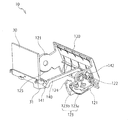
- FIG. 1 is a perspective view illustrating an outline of a head-up display device in a state where a lid is opened and a display unit is in an upright use position (hereinafter referred to as “open state”) in an embodiment of the present invention.
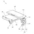
- FIG. 2 is a perspective view corresponding to FIG. 1 in a state where a lid is closed and a display unit is stored (hereinafter referred to as “closed state”).
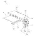
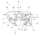
- FIG. 4 is a perspective view corresponding to FIG. 1 in an open state centered on a first link.
- FIG. 4 is a perspective view corresponding to FIG. 3 in a closed state with a first link as a center.
- FIG. 4 is a perspective view of the open state corresponding to FIG. 3 with the display arm portion omitted.
- FIG. 1 is a perspective view illustrating an outline of a head-up display device in a state where a lid is opened and a display unit is in an upright use position (hereinafter referred to as “open state”) in an embodiment of
- FIG. 6 is a perspective view of a closed state corresponding to FIG. 5 with a display arm portion omitted.
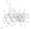
- FIG. 8 is a left side view showing an outline of a head-up display device in an open state.
- FIG. 8 is a left side view of an open state corresponding to FIG. 7 with some parts removed.
- FIG. 8 is a left side view corresponding to FIG. 7 in a closed state.
- FIG. 10 is a left side view of the closed state corresponding to FIG. 9 with some parts removed.
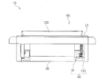
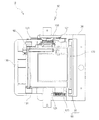
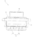
- FIG. 10 is a plan view (closed state) corresponding to FIG. 9. It is a front view (closed state) of FIG.
- FIG. 12 is a right side view (closed state) of FIG. 11.
- FIG. 12 is a rear view (closed state) of FIG. 11.
- FIG. 12 is a bottom view (closed state) of FIG. 11. It is a top view (open state) corresponding to FIG. It is a front view (open state) of FIG. It is a right view (open state) of FIG. It is a rear view (open state) of FIG. It is a bottom view (open state) of FIG.
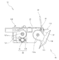
- FIG. 3 is a partially enlarged view (open state) of the first lid side of FIG. 2.
- FIG. 21 is a partially enlarged view (closed state) corresponding to FIG. 20 on the first lid side of FIG. 10.
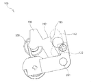
- FIG. 22 is a partially enlarged view (open state) of the link protection mechanism of FIG. 21.
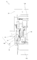
- FIG. 8 is a partially enlarged view (open state) of the second lid side of FIG. 7.
- FIG. 25 is a partially enlarged view (closed state) on the second lid side of FIG. 9 corresponding to FIG. 24.
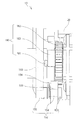
- FIG. 3 is a partially enlarged view (open state) of the angle adjustment mechanism of FIG. 2.
- FIG. 16 is a partially enlarged view (closed state) on the upper side of FIG. 15.
- FIG. 21 is a partially enlarged view (open state) on the upper side of FIG. 20.
- FIG. 28 is a partially enlarged view (closed state) of FIG. 27.
- reference numeral 10 denotes a head-up display device. Although not shown, the device 10 is fixed to an upper part of an instrument panel of an automobile and is opened by an opening operation. As shown in FIGS. 5, 7 and 8, the display unit 30 opens upward in an upright manner. As shown in FIGS. 1 to 10, the apparatus 10 is roughly divided into the following parts and mechanisms.
- the main body 20 includes the following parts when roughly classified. Each part of the main body 20 is not limited to the following (1) to (4).
- (1) Opening 21 As shown in FIGS. 1 and 16, the opening 21 is located on the upper surface of the main body 20, through which the display unit 30 can rotate and is formed in, for example, a square shape.
- the storage portion 22 is located in the hollow portion of the main body 20 and can store the display portion 30.
- Flange 23 As shown in FIGS. 1 and 16, the flange portion 23 borders the periphery of the opening portion 21.
- the display unit 30 can display information from various instruments in the driver's seat and constitutes a display unit.
- the structure of the display unit 30 is not limited to that described above, and for example, a liquid crystal display may be used.
- the display unit 30 includes the following units.
- (1) Display arm 31 As shown in FIGS. 3 and 4, the display arm portion 31 is positioned at one end portion of the display portion 30, and is formed as a pair on both the left and right sides in the width direction of the display portion 30.
- the display arm portion 31 is pivotally fixed to the opposite left and right side surfaces facing the opening 21 of the main body 20 via an arm shaft 32 and connected to the lid body 40 via a link mechanism 50 described later.
- the front window side of the instrument panel is the front in the traveling direction and the driver's seat side is the rear.
- the display arm 31 is pivoted toward the front of the opening 21, and the display 30 Is stored in the storage portion 22 of the main body 20 with its free end facing rearward and its display surface facing downward (see FIGS. 2, 4 and 6; Also referred to as “position”.)
- the display arm 31 is rotated around the arm shaft 32, as shown in FIGS. 1, 3, 5, 7, and 8, the display arm 31 is substantially upright so as to protrude from the opening 21.
- the display surface faces rearward in the traveling direction of the vehicle, that is, toward the driver (hereinafter also referred to as “use state”).
- the lid body 40 is pivotally fixed to the main body 20 so as to open and close the opening 21.
- the lid 40 is roughly divided into the following parts. The following (1) and (2) will be described later.
- First lid 120 Second lid 130
- the lid 40 is composed of the two first and second lids 120 and 130, but is not limited thereto, and may be composed of one lid or three or more lids.
- (1st lid 120) 3 to 6 the first lid 120 is located on one half of the opening 21 of the main body 20, that is, on the rear side (driver side) in the traveling direction, and opens and closes the rear half. It is connected to the display unit 30 and a second lid 130 described later via a link mechanism 50 described later.
- the second lid 130 described later is the other half of the opening 21 of the main body 20, that is, the front side (front window).
- the first half 120 is connected to the first lid 120 via a link mechanism 50 described later.
- the first lid 120 has a first arm portion 121, which will be described later, positioned at one end thereof, pivoted to the rear side of the opening 21, and the second lid 130 is shown in FIG.
- a second arm portion 131 which will be described later, located at one end portion is pivoted to the front side of the opening portion 21.
- the first and second lids 120, 130 are closed and the free ends of the first and second lids 120, 130 face each other at a substantially central portion before and after the opening 21.
- the first lid 120 includes the following parts when roughly classified. The following (1) to (5) will be described later.
- First arm portion 121 (2) Guide hole 122 (3) Cam groove 123 (4)
- each part of the first lid 120 is not limited to the above (1) to (5).
- First arm part 121 As shown in FIGS. 3 to 6, the first arm portion 121 is located at one end portion of the first lid 120 and is formed as a pair on the left and right sides in the width direction of the first lid 120.
- the first arm portion 121 is located on the rear side of the opening portion 21 and is fixed to the opposite left and right side surfaces facing the opening portion 21 of the main body 20 via the first shaft 121a.
- the display unit 30 and the second lid 130 are connected to each other.
- Guide hole 122 As shown in FIGS. 3 to 6 and FIGS. 21 to 23, the guide hole 122 is located on one side (left side) of the first arm part 121 and is located on one end of a first link 140 (to be described later) of the link mechanism 50.
- the pin 142 fits in a movable manner.
- the guide hole 122 penetrates the front and back surfaces of the first arm portion 121 and is formed in an arc shape centered on the first shaft 121a.
- the cam groove 123 is formed in an arc shape around the first shaft 121a of the first arm portion 121 on one side (left side), and is engaged with a trace pin 160 (to be described later) of the lock mechanism 70.
- the first lid 120 is locked in the closed position.
- the cam groove 123 forms a lock mechanism 70 together with a trace pin 160 described later.
- the structure of the cam groove 123 will be described later in the column of the lock mechanism 70.
- the follower portion 124 is positioned at the end portion of the first arm portion 121 on one side (left side), engages with the drum 180 of the angle adjustment mechanism 80, and is in the upright use position. It is for adjusting the opening angle of 30.
- the follower portion 124 constitutes an angle adjusting mechanism 80 together with a drum 180 described later. The structure of the follower portion 124 will be described later in the column of the angle adjustment mechanism 80. (Gear part 125) As shown in FIGS.
- the gear portion 125 is located on the first arm portion 121 on the other side (right side) and is formed in an arc shape around the first shaft 121 a,
- the damper mechanism 90 meshes with a gear fixed to a later-described rotary damper 91, and brakes the opening and closing movement of the first lid 120.
- the second lid 130 is located on the other half of the opening 21 of the main body 20, that is, on the front side (front window side). This is for opening and closing the half, and is connected to the first lid 120 via a link mechanism 50 described later.
- the second lid 130 includes the following parts when roughly classified.
- Second arm 131 (2) Inclined surface 132 (3) Connecting hole 133 (4) Second link spring 134 Note that each part of the second lid 130 is not limited to the above (1) to (4).
- the second arm portion 131 is positioned at one end portion of the second lid 130 and is formed as a pair on the left and right sides in the width direction of the second lid 130.
- the second arm portion 131 is located on the front side of the opening portion 21 and is fixed to the opposite left and right side surfaces facing the opening portion 21 of the main body 20 via the second shaft 131a.
- To the first lid 120. (Inclined surface 132) As shown in FIGS. 7 to 10, the inclined surface 132 is located at the free end of the second lid 130 and is formed by inclining the back surface facing the opening 21 toward the second arm portion 131. That is, the inclined surface 132 is formed by gradually reducing the thickness of the free end portion of the second lid 130 toward the end surface of the tip.
- the coupling hole 133 is formed with a clearance that allows the movement of the movable shaft 152 and breaks the transmission of the rotational force, that is, a large-diameter portion 133b described later, by unlocking the first lid 120 by a pressing operation.
- the clearance was formed from the large diameter part 133b, it is not limited to this.
- the connection hole 133 is formed from two large and small circles that penetrate the front and back surfaces of the second arm portion 131.
- connection hole 133 includes the following parts.
- each part of the connection hole 133 is not limited to following (1) and (2).
- (1) Small diameter part 133a As shown in FIGS. 24 and 25, the small-diameter portion 133a has a movable shaft 152 that is urged by a second link spring 134 described later.
- the large-diameter portion 133b communicates with the small-diameter portion 133a, has an inner diameter larger than that of the small-diameter portion, and generates clearance between the small-diameter portion 133a.
- the second link spring 134 is attached to the second arm portion 131 on one side (left side), and fits into the connection hole 133.
- the movable shaft 152 located at one end is urged toward the small diameter portion 133a of the connecting hole 133.
- Link mechanism 50 As shown in FIGS. 1 to 10, the link mechanism 50 is for connecting the display unit 30, the first lid 120, and the second lid 130 to each other.
- the link mechanism 50 is roughly divided into the following parts. The following (1) and (2) will be described later.
- First link 140 Second link 150
- the link mechanism 50 was comprised from the two 1st, 2nd links 140 and 150, it is not limited to this, You may comprise from one link or may comprise from 3 or more links.
- First link 140 As shown in FIGS. 3 to 6, 8 and 10, the first link 140 connects the display unit 30 and the first lid 120 to each other, and is formed in a long plate shape.
- the first link 140 includes the following parts. In addition, each part of the 1st link 140 is not limited to following (1) and (2).
- (1) Support shaft 141 As shown in FIGS. 3 to 6, 8 and 10, the support shaft 141 is positioned at one end portion of the first link 140 and is pivotally fixed to the display arm portion 31 on one side (left side) of the display portion 30. Yes.
- Link pin 142 As shown in FIGS. 3 to 6, 8 and 10, the link pin 142 is located at the other end of the first link 140 and penetrates the guide hole 122 of the first arm 121 on one side of the first lid 120. Then, it engages with a stopper 190 described later of the link protection mechanism 100.
- (Second link 150) As shown in FIGS. 1, 2, 7, 9, and 10, the second link 150 connects the first lid 120 and the second lid 130 to each other, and has a long plate shape. Is formed.
- the second link 150 includes the following units. The following (1) and (2) will be described later.
- (1) Fixed shaft 151 (2) Movable shaft 152
- each part of the 2nd link 150 is not limited to above-mentioned (1) and (2).
- (Fixed shaft 151) As shown in FIGS. 1, 2, 7, 9, and 10, the fixed shaft 151 is located at one end of the second link 150, and the first arm portion 121 on one side (left side) of the first lid 120. It is fixed to the shaft.
- (Movable shaft 152) As shown in FIGS. 24 and 25, the movable shaft 152 is located at the other end of the second link 150 and fits into the connection hole 133 of the second arm portion 131 on one side (left side) of the second lid 130.
- the movable shaft 152 includes the following parts. Each part of the movable shaft 152 is not limited to the following (1) to (3).
- First shaft part 153 As shown in FIG. 29, the first shaft portion 153 is located on the distal end side in the axial direction, has an outer diameter larger than the inner diameter of the small diameter portion 133a of the connection hole 133, and has an outer diameter equal to or smaller than the inner diameter of the large diameter portion 133b. Is.
- Second shaft portion 154 As shown in FIG. 29, the second shaft portion 154 is adjacent to the first shaft portion 153 and has an outer diameter equal to or smaller than the inner diameter of the small diameter portion 133a.
- Third shaft portion 155 As shown in FIG. 29, the third shaft portion 155 is adjacent to the second shaft portion 154 and has a larger outer diameter than the inner diameter of the small diameter portion 133a.
- the length of the second shaft portion 154 in the axial direction is set larger than the sum of the depth of the connection hole 133 and the thickness of the wire of the second link spring 134.
- the movable shaft 152 has the first shaft portion 153 located at the tip thereof inserted into the large diameter portion 133b of the connecting hole 133, and the second shaft portion 154 is slid from the large diameter portion 133b toward the small diameter portion 133a. As a result, the large-diameter first shaft portion 153 cannot be removed from the small-diameter portion 133a.
- the second link spring 134 is fitted into the second shaft portion 154 and is positioned between the large-diameter third shaft portion 155 and the second arm portion 131. .
- the movable shaft 152 is urged toward the end where the small-diameter portion 133a stops due to the spring force of the second link spring 134.
- Drive spring 60 As shown in FIGS. 27 and 28, the driving spring 60 is attached to the back surface side of the main body 20, and urges the display unit 30 toward the use position opened upward by the compression restoring force thereof.
- One end of the driving spring 60 is hooked on the back side of the main body 20, and the other end is hooked on the display arm 31 on one side of the display unit 30.
- the urging force is transmitted to the first lid 120 via the first link 140, and the first lid 120 is moved upward. It is urged in the direction to open toward. Further, the urging force that opens the first lid 120 upward is transmitted to the second lid 130 through the second link 150, and the second lid 130 is urged in a direction to open upward.
- the locking mechanism 70 is for locking the lid body 40 in the closed position against the urging force of the driving spring 60.
- the lock mechanism 70 is disposed between the main body 20 and the first lid 120, the present invention is not limited to this, and the display unit 30, the first lid 120, and the second lid 130 are connected to each other. Therefore, it may be disposed between the main body 20 and the second lid 130 or between the main body 20 and the display unit 30.
- the lock mechanism 70 includes a lock release mechanism, and can be released by an operator's release operation.
- the locked state can be released by pushing the closed first lid 120 downward.
- the unlocking operation of the locked state is performed by pushing the first lid 120.
- the present invention is not limited to this, and a button for the releasing operation may be provided separately.
- the lock mechanism 70 includes the following parts when roughly classified. The parts of the lock mechanism 70 are not limited to the following (1) to (3).
- Cam groove 123 of the first arm part 121 As shown in FIGS. 21 and 22, the cam groove 123 is formed in the first arm portion 121 on one side (left side), and roughly includes a sliding portion 123a and a lock portion 123b.
- the sliding part 123a extends long along the rotation direction of the first arm part 121.
- the lock portion 123b is located at the distal end portion of the first arm portion 121 and has a heart cam shape that can lock a trace pin 160 described later.
- the angle adjusting mechanism 80 includes the following parts when roughly classified.
- the parts of the angle adjustment mechanism 80 are not limited to the following (1) and (2).
- (1) Drum 180 As shown in FIGS. 26 and 29, the drum 180 is pivotally fixed to the side surface of the main body 20 via a drum shaft 181.
- the drum 180 is roughly divided into a substantially circular operation unit 182 that is rotatably supported on the side surface of the main body 20 via a drum shaft 181 and a drum shaft 181 that rotates integrally coaxially with the operation unit 182. And a circular cam portion 183 that is in contact with the follower portion 124 of the first arm portion 121.
- the drum shaft 181, the operation part 182 and the cam part 183 are located inside the main body 20 as shown in FIG. 26, and the upper part of the operation part 182 is a hole in the flange part 23 as shown in FIGS. It protrudes through the portion 24 to the upper surface of the flange portion 23.
- the operation unit 182 has an uneven portion formed alternately along the circumferential direction around the operation unit 182 so as to prevent slippage when rotating with a finger.
- Follower part 124 of the first arm part 121 As shown in FIG. 26, the follower portion 124 is formed on the first arm portion 121 on one side (left side), and abuts against the cam portion 183 of the drum 180 in a state where the display portion 30 is opened to an upright use position. Is.
- the follower portion 124 protrudes in a substantially U-shaped curved shape toward the drum 180.
- the follower part 124 protruded in the substantially U-shaped curved surface shape, it is not limited to this, You may make it protrude in a substantially semicircle and a substantially C-shape.
- the damper mechanism 90 is for preventing the display unit 30 from rotating suddenly by the spring force of the driving spring 60.
- the damper mechanism 90 is roughly divided into the following parts.
- the parts of the damper mechanism 90 are not limited to the following (1) and (2).
- (1) Rotating damper 91 Although not shown, the rotary damper 91 uses a viscous resistance such as silicone oil, and is fixed to the side surface of the main body 20 as shown in FIGS.
- the oil-type damper was illustrated as the rotation damper 91, it is not limited to this, A mechanical governor etc. may be sufficient. Further, the rotary damper 91 is exemplified as the damper mechanism 90, but the present invention is not limited to this, and a piston / cylinder type damper may be used.
- (2) Gear portion 125 of the first arm portion 121 As shown in FIGS. 3, 5, 13, and 18, the gear portion 125 is formed on the first arm portion 121 on the other side (right side) of the first lid 120 and meshes with the gear of the rotary damper 91. It is. The gear portion 125 is formed along the circumferential direction around the first shaft 121a of the first arm portion 121.
- Link protection mechanism 100 As shown in FIGS. 21 to 23, the link protection mechanism 100 tries to forcefully open the display unit 30 in the use position opened upright, and the link mechanism 50 rotates when the display unit 30 is overloaded. This is to protect the link mechanism 50 by interrupting the transmission of force.
- the link protection mechanism 100 includes the following parts when roughly classified.
- the parts of the link protection mechanism 100 are not limited to the following (1) to (3).
- (1) Stopper 190 As shown in FIGS. 21 to 23, the stopper 190 is pivotally fixed to the first arm portion 121 on one side (left side) of the first lid 120 via a stopper shaft 191 and is shown in FIGS. 21 and 22.
- the display pin 30 As described above, the display pin 30 is engaged with the link pin 142 of the first link 140, and the display unit 30 and the first lid 120 are connected. When hooked, as shown in FIG. 23, the link pin 142 can be engaged and disengaged.
- the stopper 190 has one end fixed to the first arm part 121 via a stopper shaft 191 and the other end free end engaged with the link pin 142 fitted therein.
- a part 192 is provided.
- the engaging portion 192 is formed in a substantially L-shaped cross section with one side open, and when a force for forcibly opening the display portion 30 is applied, the link pin 142 of the first link 140 escapes from the open surface. Further, it is configured to be movable in the direction of the stopper shaft 191 while being slidably contacted along the side surface.
- a tapered shape 193 for guiding the link pin 142 is formed on the side surface of the stopper 190 in a state of being engaged with and disengaged from the link pin 142.
- the taper shape 193 faces the open end of the engaging portion 192, and protrudes in a substantially triangular shape in cross section with the inclined surface facing the stopper shaft 191.
- Stopper spring 200 The stopper spring 200 urges the engaging portion 192 located on the free end side of the stopper 190 in a direction approaching the link pin 142, as shown in FIGS.
- Link pin 142 of the first link 140 21 to 23 the link pin 142 of the first link 140 fits into and engages with the engaging portion 192 of the stopper 190, and the first link 140 and the first lid 120 are connected via the stopper 190.
- One arm unit 121 is connected to each other.
- the link pin 142 fits into the guide hole 122 of the first arm portion 121 of the first lid 120 and moves in a direction in which the link pin 142 contacts and separates from the engaging portion 192 along the guide hole 122.
- shielding plate 110 As shown in FIGS. 7, 8, 1, and 16, the shielding plate 110 is located between the display unit 30 and the second lid 130, and rotates with respect to the display arm unit 31 via the shielding shaft 111.
- the second lid 130 is pivotally supported and shields the gap between the second lid 130 and the main body 20 when the second lid 130 is open.
- the shielding plate 110 is biased in the opening direction by a shielding plate spring 112. (How to use the head-up display device 10) Next, a method for using the head-up display device 10 having the above-described configuration will be described. As shown in FIGS. 1, 9, and 10, the display unit 30 and the shielding plate 110 are housed in the main body 20 when the lid 40 is closed.
- the first lid 120 When the display unit 30 is used, the first lid 120 may be pushed down toward the main body 20. When the first lid 120 is pushed up, the lock state of the lock mechanism 70 is released. That is, the trace pin 160 located in the heart cam-shaped lock part 123b of the cam groove 123 is pulled out of the lock part 123b and proceeds to the sliding part 123a that extends long along the rotation direction of the first arm part 121. Proceed along the sliding part 123a.
- the first lid 120 can be rotated, and the display unit 30 connected to the first lid 120 by the first link 140 can be rotated.
- the display unit 30 projects upward from the opening 21 of the main body 20 as shown in FIGS. 1, 3, 5, 7, and 8 by the spring force of the driving spring 60, and stands upright. Rotate towards the open use position.
- the first lid 120 is opened via the first link 140, and the second lid 130 is further opened via the second link 150.
- the gear portion 125 formed on the first arm portion 121 on the side without the first link 140 and the side surface of the main body 20 Due to the meshing of the rotary damper 91 fixed to the gear, the rotary damper 91 rotates and a braking force is applied. The braking force is also transmitted to the display unit 30 via the first link 140, and the display unit 30 is released quietly and slowly.
- the shielding plate 110 is also opened by the shielding plate spring 112, and between the opened second lid 130 and the main body 20. Shield the gap.
- the display unit 30 is at the maximum open position, as shown in FIG. It is regulated at the position where it contacts with 124.
- the display unit 30 at the use position is irradiated with display light from a display device mounted on the inside or outside of the apparatus 10 so that the driver can visually recognize the reflected light.
- Interference prevention operation of the first and second lids 120 and 130 During the unlocking operation, the first lid 120 is pushed down toward the main body 20, but at this time, the second lid 130 connected via the second link 150 is prevented from rotating.
- the display unit 30 rotates in the closing direction via the first link 140.
- the second lid 130 rotates in the closing direction via the second link 150.
- the shield plate 110 is pushed in the closing direction by being pushed by the second lid 130.
- the first lid 120 is pushed back slightly through the first link 140 by the spring force of the driving spring 60, and the trace pin 160 is locked to the heart cam-shaped lock portion 123b as shown in FIG. Then, the lock mechanism 70 is locked. Therefore, the display unit 30 is stored in the storage unit 22 of the main body 20, and the opening 21 is closed by the first and second lids 120 and 130 as shown in FIGS. 2, 8, and 9. (How to adjust the opening angle of the display unit 30)
- the operation unit 182 of the drum 180 protruding from the upper surface of the flange unit 23 may be rotated as shown in FIG.
- the eccentric cam portion 183 is integrally rotated, and the follower portion 124 that protrudes from the cam portion 183 and the first arm portion 121 of the first lid 120 into a substantially U-shaped curved surface shape.
- the contact position of is changed. That is, when the follower portion 124 comes into contact with the circumferential surface of the cam portion 183 separated from the drum shaft 181, the first lid 120 rotates in the closing direction, and the display portion 30 is closed in the closing direction via the first link 140. And the opening angle of the display unit 30 decreases.
- the first lid 120 rotates in the opening direction, and the display portion 30 is connected via the first link 140. Rotating in the opening direction increases the opening angle of the display unit 30.
- the adjustment range of the opening angle of the display unit 30 is set to plus / minus 5 degrees, but is not limited thereto. (Protection method against excessive opening of display unit 30)
- the connection state between the first link 140 and the first lid 120 is released, and the transmission of the overload applied to the display unit 30 to the link mechanism 50 is interrupted.
- the overload applied to the display unit 30 is released, the display unit 30 tries to return to the initial position by the spring force of the driving spring 60.
- the stopper 190 is also rotated in the direction approaching the link pin 142 by the stopper spring 200.
Landscapes
- Engineering & Computer Science (AREA)
- Mechanical Engineering (AREA)
- Fittings On The Vehicle Exterior For Carrying Loads, And Devices For Holding Or Mounting Articles (AREA)
Abstract
両リッドの間の干渉や、リッドと本体との間の干渉やそれらを原因とする操作不良を減少することを目的とする。リンク(例えば第2リンク)の一端部は、第1リッドのアーム部(例えば第1アーム部)に軸止される。リンク(例えば第2リンク)の他端部と、第2リッドのアーム部(例えば第2アーム部)との間には、軸(例えば可動軸)と、当該軸(例えば可動軸)がはまり込む孔(例えば連結孔)とをもうけている。孔(例えば連結孔)には、第1リッドの押圧操作によるロック解除により、軸(例えば可動軸)の移動を許容し、回転力の伝達を断つクリアランス(例えば大径部)が形成されている。
Description
この発明は、蓋体のリンク構造に関し、2個のリッドのうち、一方の第1リッドを押圧操作してロック機構のロック状体を解除する際に、他方の第2リッドが動かないようにようすることで、両リッドの間の干渉を防止することができるようにしたものである。
従来、本体の開口部に、両開きの二枚のリッドを軸止し、両リッドの自由端部を突き合わせて状態でロック構造によりロックし、突き合わせた両リッドの一方の自由端部を押圧操作することで、ロック構造のロック状態を解除可能に構成した「回動体のロック構造、および収納装置」が知られている(例えば特許文献1の段落番号「0020」及び図10参照)。
しかし、上記した従来の「回動体のロック構造、および収納装置」では、突き合わせた両リッドの一方の自由端部を押圧操作した際、他方のリッドも動くため、両リッドの自由端部先端同士が干渉し易いという問題点があった。
両リッドの自由端部先端同士が干渉すると、十分な押圧操作ができず、ロック構造のロック状態の解除が不確実となり、操作不良の原因ともなり易かった。両リッドの自由端部先端同士の干渉を避けるため、突き合わせた状態の両リッドの自由端部先端間の対向間隔を広げると、見栄えが悪くなるという弊害がある。
両リッドの自由端部先端同士が干渉すると、十分な押圧操作ができず、ロック構造のロック状態の解除が不確実となり、操作不良の原因ともなり易かった。両リッドの自由端部先端同士の干渉を避けるため、突き合わせた状態の両リッドの自由端部先端間の対向間隔を広げると、見栄えが悪くなるという弊害がある。
また、従来の「回動体のロック構造、および収納装置」では、リッドの裏面と、当該リッドを閉じた状態でその裏面と対向する本体の開口部の開口端面との間に、当該リッドを押圧操作するための隙間が必要となるが、当該リッドの裏面と本体側の開口端面とが干渉し易いという問題点があった。
リッドの裏面と本体側の開口端面とが干渉すると、十分な押圧操作ができず、ロック構造のロック状態の解除が不確実となり、操作不良の原因ともなり易かった。リッドの裏面と本体側の開口端面との干渉を避けるため、リッドの裏面と本体側の開口端面との間の隙間を広げると、見栄えが悪くなるという弊害がある。
リッドの裏面と本体側の開口端面とが干渉すると、十分な押圧操作ができず、ロック構造のロック状態の解除が不確実となり、操作不良の原因ともなり易かった。リッドの裏面と本体側の開口端面との干渉を避けるため、リッドの裏面と本体側の開口端面との間の隙間を広げると、見栄えが悪くなるという弊害がある。
そこで、本発明は、上記した従来の技術の有する問題点に鑑みてなされたものであり、その目的とするところは、両リッドの間の干渉や、リッドと本体との間の干渉やそれらを原因とする操作不良を減少することができるようにしたものである。
本発明は、上記した目的を達成するためになされたものであり、本発明は、次の点を特徴とする。
第1に、蓋体のリンク構造(例えばリンク機構)には、次の構成を備える。
(1)本体
本体は、上面に開口部を有する中空のものである。
(2)蓋体
蓋体は、本体に回動可能に軸止され、本体の開口部を開閉するものである。
(1)本体
本体は、上面に開口部を有する中空のものである。
(2)蓋体
蓋体は、本体に回動可能に軸止され、本体の開口部を開閉するものである。
第2に、蓋体は、一端部に位置するアーム部(例えば第1、第2アーム部)を有し、当該アーム部(例えば第1、第2アーム部)が本体の開口部に臨む相対向する側面にそれぞれ軸止され、他端自由端部が本体の開口部上で互いに突き合う2個のリッド(例えば第1、第2リッド)から構成されている。
第3に、2個のリッド(例えば第1、第2リッド)のうち、一方の第1リッドには、当該第1リッドの押圧操作によりロックを解除可能なロック機構を備える。
第4に、リッド(例えば第1、第2リッド)のうち、他方の第2リッドは、回転力を伝達可能なリンク(例えば第2リンク)を介して第1リッドと連結される。
第4に、リッド(例えば第1、第2リッド)のうち、他方の第2リッドは、回転力を伝達可能なリンク(例えば第2リンク)を介して第1リッドと連結される。
第5に、リンク(例えば第2リンク)の一端部は、第1リッドのアーム部(例えば第1アーム部)に軸止される。
第6に、リンク(例えば第2リンク)の他端部と、第2リッドのアーム部(例えば第2アーム部)との間には、軸(例えば可動軸)と、当該軸(例えば可動軸)がはまり込む孔(例えば連結孔)とを設けている。
第6に、リンク(例えば第2リンク)の他端部と、第2リッドのアーム部(例えば第2アーム部)との間には、軸(例えば可動軸)と、当該軸(例えば可動軸)がはまり込む孔(例えば連結孔)とを設けている。
第7に、孔(例えば連結孔)には、第1リッドの押圧操作によるロック解除により、軸(例えば可動軸)の移動を許容し、回転力の伝達を断つクリアランス(例えば大径部)が形成されている。
本発明は、次の点を特徴としてもよい。
本発明は、次の点を特徴としてもよい。
第1に、軸(例えば可動軸)を、リンク(例えば第2リンク)に設ける。
第2に、孔(例えば連結孔)を、第2リッドのアーム部(例えば第2アーム部)に設ける。
第3に、第2リッドのアーム部(例えば第2アーム部)には、軸(例えば可動軸)を孔(例えば連結孔)の端部に位置させる方向に付勢するスプリング(例えば第2リンク用バネ)を設けた。
この好ましい態様によれば、リンクのガタ付きを押さえることができるばかりでなく、ロック解除後のリッドの開放をスムーズに行うことができる。
本発明は、次の点を特徴としてもよい。
第2に、孔(例えば連結孔)を、第2リッドのアーム部(例えば第2アーム部)に設ける。
第3に、第2リッドのアーム部(例えば第2アーム部)には、軸(例えば可動軸)を孔(例えば連結孔)の端部に位置させる方向に付勢するスプリング(例えば第2リンク用バネ)を設けた。
この好ましい態様によれば、リンクのガタ付きを押さえることができるばかりでなく、ロック解除後のリッドの開放をスムーズに行うことができる。
本発明は、次の点を特徴としてもよい。
すなわち、孔(例えば連結孔)には、次の構成を備える。
(1)小径部
小径部は、スプリング(例えば第2リンク用バネ)により付勢された軸(例えば可動軸)が位置するものである。
(1)小径部
小径部は、スプリング(例えば第2リンク用バネ)により付勢された軸(例えば可動軸)が位置するものである。
(2)大径部
大径部は、小径部に連通し、当該小径部より内径が大きく、小径部との間にクリアランスを発生させるためのものである。
この好ましい態様によれば、リンクの組み立てを容易に行えるばかりでなく、作動時の軸の移動をスムーズに行うことができる。
本発明は、次の点を特徴としてもよい。
大径部は、小径部に連通し、当該小径部より内径が大きく、小径部との間にクリアランスを発生させるためのものである。
この好ましい態様によれば、リンクの組み立てを容易に行えるばかりでなく、作動時の軸の移動をスムーズに行うことができる。
本発明は、次の点を特徴としてもよい。
すなわち、軸(例えば可動軸)には、次の構成を備える。
(1)第1軸部
第1軸部は、軸方向の先端側に位置し、小径部の内径より外径が太く、大径部の内径以下の外径を有するものである。
(1)第1軸部
第1軸部は、軸方向の先端側に位置し、小径部の内径より外径が太く、大径部の内径以下の外径を有するものである。
(2)第2軸部
第2軸部は、第1軸部と隣接し、小径部の内径以下の外径を有するものである。
(3)第3軸部
第3軸部は、第2軸部に隣接し、小径部の内径より外径の太いものである。
この好ましい態様によれば、リンクの組み立てを容易に行えるばかりでなく、作動時の軸の移動を、ガタ無く、スムーズに行うことができる。
本発明は、次の点を特徴としてもよい。
第2軸部は、第1軸部と隣接し、小径部の内径以下の外径を有するものである。
(3)第3軸部
第3軸部は、第2軸部に隣接し、小径部の内径より外径の太いものである。
この好ましい態様によれば、リンクの組み立てを容易に行えるばかりでなく、作動時の軸の移動を、ガタ無く、スムーズに行うことができる。
本発明は、次の点を特徴としてもよい。
すなわち、第2軸部の軸方向の長さは、孔(例えば連結孔)の深さと、スプリング(例えば第2リンク用バネ)の線材の太さとの総和より大きく設定している。
この好ましい態様によれば、スプリングが容易に取り付けることができるばかりでなく、スプリングによるトルクの安定化を図ることができる。
この好ましい態様によれば、スプリングが容易に取り付けることができるばかりでなく、スプリングによるトルクの安定化を図ることができる。
本発明は、以上のように構成されているので、2個のリッドのうち、一方の第1リッドを押圧操作してロック機構のロック状体を解除する際に、他方の第2リッドが動かないようにようすることで、両リッドの間の干渉や、リッドと本体との間の干渉やそれらを原因とする操作不良を減少することができる。
図1~10中、10は、ヘッドアップディスプレイ装置を示し、当該装置10は、図示しないが、自動車のインストルメントパネルの上部に埋設状に固定され、開放操作により、図1、図3、図5、図7及び図8に示すように、表示部30が上方に直立状に開く構造となっている。
装置10は、図1~10に示すように、大別すると、次のパーツ及び機構を備える。
装置10は、図1~10に示すように、大別すると、次のパーツ及び機構を備える。
(1)本体20
(2)表示部30
(3)蓋体40
(4)リンク機構50(リンク構造)
(5)駆動用スプリング60(図27及び図28参照)
(6)ロック機構70(図21及び図22参照)
(7)角度調整機構80(図26参照)
(8)ダンパー機構90(図13及び図18参照)
(9)リンク保護機構100(図23参照)
(10)遮蔽板110
なお、装置10のパーツ及び機構は、上記した(1)~(10)に限定されない。
(本体20)
本体20は、図1及び図16に示すように、上面が開口した中空箱形に形成され、図示しないが、インストルメントパネルの上部に埋設状に固定される。
(2)表示部30
(3)蓋体40
(4)リンク機構50(リンク構造)
(5)駆動用スプリング60(図27及び図28参照)
(6)ロック機構70(図21及び図22参照)
(7)角度調整機構80(図26参照)
(8)ダンパー機構90(図13及び図18参照)
(9)リンク保護機構100(図23参照)
(10)遮蔽板110
なお、装置10のパーツ及び機構は、上記した(1)~(10)に限定されない。
(本体20)
本体20は、図1及び図16に示すように、上面が開口した中空箱形に形成され、図示しないが、インストルメントパネルの上部に埋設状に固定される。
本体20には、図1及び図16に示すように、大別すると、次の各部を備える。
なお、本体20の各部は、次の(1)~(4)に限定されない。
(1)開口部21
開口部21は、図1及び図16に示すように、本体20の上面に位置し、表示部30が回動して通過可能なものであり、例えば方形に形成されている。
なお、本体20の各部は、次の(1)~(4)に限定されない。
(1)開口部21
開口部21は、図1及び図16に示すように、本体20の上面に位置し、表示部30が回動して通過可能なものであり、例えば方形に形成されている。
(2)収納部22
収納部22は、図1及び図16に示すように、本体20の中空部内に位置し、表示部30が収納可能なものである。
(3)フランジ部23
フランジ部23は、図1及び図16に示すように、開口部21の周囲を縁取るものである。
収納部22は、図1及び図16に示すように、本体20の中空部内に位置し、表示部30が収納可能なものである。
(3)フランジ部23
フランジ部23は、図1及び図16に示すように、開口部21の周囲を縁取るものである。
(4)孔部24
孔部24は、図1及び図16に示すように、上下に貫通し、開角度調整機構80の後述するドラム180の一部、すなわち上端部が突出可能なものである。
(表示部30)
表示部30は、運転席の各種計器類からの情報を表示可能なものであり、表示部を構成する。
孔部24は、図1及び図16に示すように、上下に貫通し、開角度調整機構80の後述するドラム180の一部、すなわち上端部が突出可能なものである。
(表示部30)
表示部30は、運転席の各種計器類からの情報を表示可能なものであり、表示部を構成する。
なお、表示部30の構造は、上述したものに限定されず、例えば液晶ディスプレイを用いても良い。
表示部30には、図1~8に示すように、次の各部を備える。
(1)表示用アーム部31
表示用アーム部31は、図3及び図4に示すように、表示部30の一端部に位置し、表示部30の幅方向の左右両側に一対形成されている。表示用アーム部31は、本体20の開口部21に臨む相対向する左右の側面にアーム軸32を介してそれぞれ軸止され、後述するリンク機構50を介して蓋体40に連結される。
表示部30には、図1~8に示すように、次の各部を備える。
(1)表示用アーム部31
表示用アーム部31は、図3及び図4に示すように、表示部30の一端部に位置し、表示部30の幅方向の左右両側に一対形成されている。表示用アーム部31は、本体20の開口部21に臨む相対向する左右の側面にアーム軸32を介してそれぞれ軸止され、後述するリンク機構50を介して蓋体40に連結される。
図示しないが、インストルメントパネルのフロントウインドウ側を、進行方向の前方とし、運転席側を後方とし、このとき、表示用アーム部31は、開口部21の前方寄りに軸止され、表示部30は、その自由端部を後方に向けとともに、その表示面を下方に向かって伏せた状態で本体20の収納部22内に収納される(図2、図4及び図6参照、以下、「収納位置」ともいう。)。これに対し、表示用アーム部31がアーム軸32を中心に回動すると、図1、図3、図5、図7及び図8に示すように、開口部21から突出するように略直立し、その表示面が車両の進行方向の後方、すなわち運転者の方向に向く(以下、「使用状態」ともいう。)。
(蓋体40)
蓋体40は、図1~10に示すように、本体20の回動可能に軸止され、開口部21を開閉するものである。
(蓋体40)
蓋体40は、図1~10に示すように、本体20の回動可能に軸止され、開口部21を開閉するものである。
蓋体40は、図1~10に示すように、大別すると、次のパーツを備える。
なお、次の(1)及び(2)については後述する。
(1)第1リッド120
(2)第2リッド130
なお、蓋体40を、2個の第1、第2リッド120,130から構成したが、これらに限定されず、1個のリッドから構成したり、或いは3個以上のリッドから構成しても良い。
(第1リッド120)
第1リッド120は、図3~6に示すように、本体20の開口部21の片半部、すなわち進行方向の後方側(運転者側)に位置し、後方側の片半部を開閉するものであり、後述するリンク機構50を介して表示部30及び後述する第2リッド130に連結されている。これに対し、後述する第2リッド130は、図1、図2、図7、図9及び図10に示すように、本体20の開口部21の他の片半部、すなわち前方側(フロントウインドウ側)に位置し、前方側の片半部を開閉するためのものであり、後述するリンク機構50を介して第1リッド120に連結されている。
なお、次の(1)及び(2)については後述する。
(1)第1リッド120
(2)第2リッド130
なお、蓋体40を、2個の第1、第2リッド120,130から構成したが、これらに限定されず、1個のリッドから構成したり、或いは3個以上のリッドから構成しても良い。
(第1リッド120)
第1リッド120は、図3~6に示すように、本体20の開口部21の片半部、すなわち進行方向の後方側(運転者側)に位置し、後方側の片半部を開閉するものであり、後述するリンク機構50を介して表示部30及び後述する第2リッド130に連結されている。これに対し、後述する第2リッド130は、図1、図2、図7、図9及び図10に示すように、本体20の開口部21の他の片半部、すなわち前方側(フロントウインドウ側)に位置し、前方側の片半部を開閉するためのものであり、後述するリンク機構50を介して第1リッド120に連結されている。
すなわち、第1リッド120は、図1~10に示すように、一端部に位置する後述する第1アーム部121が開口部21の後方側に軸止され、又、第2リッド130は、図1、図2及び図7~10に示すように、一端部に位置する後述する第2アーム部131が開口部21の前方側に軸止される。第1、第2リッド120,130は、図2、図9及び図10に示すように、閉じた状態で、両者の自由端部が開口部21の前後の略中央部で互いに突き合う。
第1リッド120には、図1~10に示すように、大別すると、次の各部を備える。
なお、次の(1)~(5)については、後述する。
(1)第1アーム部121
(2)ガイド孔122
(3)カム溝123
(4)従節部124
(5)歯車部125
なお、第1リッド120の各部は、上記した(1)~(5)に限定されない。
(第1アーム部121)
第1アーム部121は、図3~6に示すように、第1リッド120の一端部に位置し、第1リッド120の幅方向の左右両側に一対形成されている。第1アーム部121は、開口部21の後方側に位置し、本体20の開口部21に臨む相対向する左右の側面に第1軸121aを介してそれぞれ軸止され、後述するリンク機構50を介して表示部30及び第2リッド130に連結される。
(ガイド孔122)
ガイド孔122は、図3~6及び図21~23に示すように、片側(左側)の第1アーム部121に位置し、リンク機構50の後述する第1リンク140の一端部に位置するリンクピン142が移動可能にはまり込むものである。
なお、次の(1)~(5)については、後述する。
(1)第1アーム部121
(2)ガイド孔122
(3)カム溝123
(4)従節部124
(5)歯車部125
なお、第1リッド120の各部は、上記した(1)~(5)に限定されない。
(第1アーム部121)
第1アーム部121は、図3~6に示すように、第1リッド120の一端部に位置し、第1リッド120の幅方向の左右両側に一対形成されている。第1アーム部121は、開口部21の後方側に位置し、本体20の開口部21に臨む相対向する左右の側面に第1軸121aを介してそれぞれ軸止され、後述するリンク機構50を介して表示部30及び第2リッド130に連結される。
(ガイド孔122)
ガイド孔122は、図3~6及び図21~23に示すように、片側(左側)の第1アーム部121に位置し、リンク機構50の後述する第1リンク140の一端部に位置するリンクピン142が移動可能にはまり込むものである。
ガイド孔122は、第1アーム部121の表裏面に貫通し、第1軸121aを中心とした円弧状に形成されている。
(カム溝123)
カム溝123は、図21及び図22に示すように、片側(左側)の第1アーム部121の第1軸121aを中心に円弧状に形成され、ロック機構70の後述するトレースピン160に係合し、第1リッド120を閉位置にロックするためのものである。カム溝123は、後述するトレースピン160とともにロック機構70を構成する。なお、カム溝123の構造については、ロック機構70の欄において後述する。
(従節部124)
従節部124は、図26に示すように、片側(左側)の第1アーム部121の端部に位置し、角度調整機構80のドラム180に係合し、直立した使用位置にある表示部30の開き角度を調整するためのものである。従節部124は、後述するドラム180とともに角度調整機構80を構成する。なお、従節部124の構造については、角度調整機構80の欄において後述する。
(歯車部125)
歯車部125は、図3、図5、図13及び図18に示すように、他の片側(右側)の第1アーム部121に位置し、第1軸121aを中心に円弧状に形成され、ダンパー機構90の後述する回転ダンパー91に固定された歯車とかみ合い、第1リッド120の開閉の動きを制動するためのものである。
(第2リッド130)
第2リッド130は、図1、図2及び図7~10に示すように、本体20の開口部21の他の片半部、すなわち前方側(フロントウインドウ側)に位置し、前方側の片半部を開閉するためのものであり、後述するリンク機構50を介して第1リッド120に連結されている。
(カム溝123)
カム溝123は、図21及び図22に示すように、片側(左側)の第1アーム部121の第1軸121aを中心に円弧状に形成され、ロック機構70の後述するトレースピン160に係合し、第1リッド120を閉位置にロックするためのものである。カム溝123は、後述するトレースピン160とともにロック機構70を構成する。なお、カム溝123の構造については、ロック機構70の欄において後述する。
(従節部124)
従節部124は、図26に示すように、片側(左側)の第1アーム部121の端部に位置し、角度調整機構80のドラム180に係合し、直立した使用位置にある表示部30の開き角度を調整するためのものである。従節部124は、後述するドラム180とともに角度調整機構80を構成する。なお、従節部124の構造については、角度調整機構80の欄において後述する。
(歯車部125)
歯車部125は、図3、図5、図13及び図18に示すように、他の片側(右側)の第1アーム部121に位置し、第1軸121aを中心に円弧状に形成され、ダンパー機構90の後述する回転ダンパー91に固定された歯車とかみ合い、第1リッド120の開閉の動きを制動するためのものである。
(第2リッド130)
第2リッド130は、図1、図2及び図7~10に示すように、本体20の開口部21の他の片半部、すなわち前方側(フロントウインドウ側)に位置し、前方側の片半部を開閉するためのものであり、後述するリンク機構50を介して第1リッド120に連結されている。
第2リッド130は、図1、図2及び図7~10に示すように、大別すると、次の各部を備える。
(1)第2アーム部131
(2)傾斜面132
(3)連結孔133
(4)第2リンク用バネ134
なお、第2リッド130の各部は、上記した(1)~(4)に限定されない。
(1)第2アーム部131
(2)傾斜面132
(3)連結孔133
(4)第2リンク用バネ134
なお、第2リッド130の各部は、上記した(1)~(4)に限定されない。
なお、次の(1)~(4)については、後述する。
(第2アーム部131)
第2アーム部131は、図1、図2及び図7~10に示すように、第2リッド130の一端部に位置し、第2リッド130の幅方向の左右両側に一対形成されている。第2アーム部131は、開口部21の前方側に位置し、本体20の開口部21に臨む相対向する左右の側面に第2軸131aを介してそれぞれ軸止され、後述するリンク機構50を介して第1リッド120に連結される。
(傾斜面132)
傾斜面132は、図7~10に示すように、第2リッド130の自由端部に位置し、開口部21に臨む裏面を第2アーム部131に向かって傾斜させて形成している。すなわち、傾斜面132は、第2リッド130の自由端部の肉厚を、先端の端面に向かって徐々に減少させることで形成している。
(第2アーム部131)
第2アーム部131は、図1、図2及び図7~10に示すように、第2リッド130の一端部に位置し、第2リッド130の幅方向の左右両側に一対形成されている。第2アーム部131は、開口部21の前方側に位置し、本体20の開口部21に臨む相対向する左右の側面に第2軸131aを介してそれぞれ軸止され、後述するリンク機構50を介して第1リッド120に連結される。
(傾斜面132)
傾斜面132は、図7~10に示すように、第2リッド130の自由端部に位置し、開口部21に臨む裏面を第2アーム部131に向かって傾斜させて形成している。すなわち、傾斜面132は、第2リッド130の自由端部の肉厚を、先端の端面に向かって徐々に減少させることで形成している。
図9及び図10に示すように、第1、第2リッド120,130を閉じた状態において、後述するロック機構70のロック状態を解除すべく、第1リッド120の自由端部を開口部21に向かって押し込んだ際に、当該自由端部が第2リッド130の傾斜面132の下側に潜り込むように回動することで、第1、第2リッド120,130の突き合う自由端部同士の干渉を防止している。
(連結孔133)
連結孔133は、図24及び図25に示すように、片側(左側)の第2アーム部131に位置し、リンク機構50の後述する第2リンク150の一端部に位置する可動軸152が移動可能にはまり込むものである。
(連結孔133)
連結孔133は、図24及び図25に示すように、片側(左側)の第2アーム部131に位置し、リンク機構50の後述する第2リンク150の一端部に位置する可動軸152が移動可能にはまり込むものである。
連結孔133には、第1リッド120の押圧操作によるロック解除により、可動軸152の移動を許容し、回転力の伝達を断つクリアランス、すなわち後述する大径部133bが形成されている。
なお、クリアランスを、大径部133bより形成したが、これに限定されない。
連結孔133は、第2アーム部131の表裏面に貫通し、大小二つの互いに連通した円から形成されている。
なお、クリアランスを、大径部133bより形成したが、これに限定されない。
連結孔133は、第2アーム部131の表裏面に貫通し、大小二つの互いに連通した円から形成されている。
具体的には、連結孔133には、図24及び図25に示すように、次の各部を備える。
なお、連結孔133の各部は、次の(1)及び(2)に限定されない。
(1)小径部133a
小径部133aは、図24及び図25に示すように、後述する第2リンク用バネ134により付勢された可動軸152が位置するものである。
なお、連結孔133の各部は、次の(1)及び(2)に限定されない。
(1)小径部133a
小径部133aは、図24及び図25に示すように、後述する第2リンク用バネ134により付勢された可動軸152が位置するものである。
(2)大径部133b
大径部133bは、図24及び図25に示すように、小径部133aに連通し、当該小径部より内径が大きく、小径部133aとの間にクリアランスを発生させるためのものである。
(第2リンク用バネ134)
第2リンク用バネ134は、図24及び図25に示すように、片側(左側)の第2アーム部131に取り付けられ、連結孔133にはまり込む、リンク機構50の後述する第2リンク150の一端部に位置する可動軸152を、連結孔133の小径部133aに向かって付勢するものである。
(リンク機構50)
リンク機構50は、図1~10に示すように、表示部30、第1リッド120、第2リッド130の三者を相互に連結するためのものである。
大径部133bは、図24及び図25に示すように、小径部133aに連通し、当該小径部より内径が大きく、小径部133aとの間にクリアランスを発生させるためのものである。
(第2リンク用バネ134)
第2リンク用バネ134は、図24及び図25に示すように、片側(左側)の第2アーム部131に取り付けられ、連結孔133にはまり込む、リンク機構50の後述する第2リンク150の一端部に位置する可動軸152を、連結孔133の小径部133aに向かって付勢するものである。
(リンク機構50)
リンク機構50は、図1~10に示すように、表示部30、第1リッド120、第2リッド130の三者を相互に連結するためのものである。
リンク機構50は、図1~10に示すように、大別すると、次のパーツを備える。
なお、次の(1)及び(2)については後述する。
(1)第1リンク140
(2)第2リンク150
なお、リンク機構50を、2本の第1、第2リンク140,150から構成したが、これに限定されず、1本のリンクから構成したり、或いは3本以上のリンクから構成しても良い。
(第1リンク140)
第1リンク140は、図3~6、図8及び図10に示すように、表示部30と第1リッド120とを相互に連結するものであり、長尺な板状に形成されている。
なお、次の(1)及び(2)については後述する。
(1)第1リンク140
(2)第2リンク150
なお、リンク機構50を、2本の第1、第2リンク140,150から構成したが、これに限定されず、1本のリンクから構成したり、或いは3本以上のリンクから構成しても良い。
(第1リンク140)
第1リンク140は、図3~6、図8及び図10に示すように、表示部30と第1リッド120とを相互に連結するものであり、長尺な板状に形成されている。
第1リンク140は、図3~6、図8及び図10に示すように、次の各部を備える。
なお、第1リンク140の各部は、次の(1)及び(2)に限定されない。
(1)支持軸141
支持軸141は、図3~6、図8及び図10に示すように、第1リンク140の一端部に位置し、表示部30の片側(左側)の表示用アーム部31に軸止されている。
なお、第1リンク140の各部は、次の(1)及び(2)に限定されない。
(1)支持軸141
支持軸141は、図3~6、図8及び図10に示すように、第1リンク140の一端部に位置し、表示部30の片側(左側)の表示用アーム部31に軸止されている。
(2)リンクピン142
リンクピン142は、図3~6、図8及び図10に示すように、第1リンク140の他端部に位置し、第1リッド120の片側の第1アーム部121のガイド孔122を貫通し、リンク保護機構100の後述するストッパー190に係合する。
(第2リンク150)
第2リンク150は、図1、図2、図7、図9及び図10に示すように、第1リッド120と第2リッド130とを相互に連結するものであり、長尺な板状に形成されている。
リンクピン142は、図3~6、図8及び図10に示すように、第1リンク140の他端部に位置し、第1リッド120の片側の第1アーム部121のガイド孔122を貫通し、リンク保護機構100の後述するストッパー190に係合する。
(第2リンク150)
第2リンク150は、図1、図2、図7、図9及び図10に示すように、第1リッド120と第2リッド130とを相互に連結するものであり、長尺な板状に形成されている。
第2リンク150は、図1、図2、図7、図9及び図10に示すように、次の各部を備える。
なお、次の(1)及び(2)については、後述する。
(1)固定軸151
(2)可動軸152
なお、第2リンク150の各部は、上記した(1)及び(2)に限定されない。
(固定軸151)
固定軸151は、図1、図2、図7、図9及び図10に示すように、第2リンク150の一端部に位置し、第1リッド120の片側(左側)の第1アーム部121に軸止されている。
(可動軸152)
可動軸152は、図24及び図25に示すように、第2リンク150の他端部に位置し、第2リッド130の片側(左側)の第2アーム部131の連結孔133にはまり込む。
なお、次の(1)及び(2)については、後述する。
(1)固定軸151
(2)可動軸152
なお、第2リンク150の各部は、上記した(1)及び(2)に限定されない。
(固定軸151)
固定軸151は、図1、図2、図7、図9及び図10に示すように、第2リンク150の一端部に位置し、第1リッド120の片側(左側)の第1アーム部121に軸止されている。
(可動軸152)
可動軸152は、図24及び図25に示すように、第2リンク150の他端部に位置し、第2リッド130の片側(左側)の第2アーム部131の連結孔133にはまり込む。
可動軸152には、図29に示すように、次の各部を備える。
なお、可動軸152の各部は、次の(1)~(3)に限定されない。
(1)第1軸部153
第1軸部153は、図29に示すように、軸方向の先端側に位置し、連結孔133の小径部133aの内径より外径が太く、大径部133bの内径以下の外径を有するものである。
なお、可動軸152の各部は、次の(1)~(3)に限定されない。
(1)第1軸部153
第1軸部153は、図29に示すように、軸方向の先端側に位置し、連結孔133の小径部133aの内径より外径が太く、大径部133bの内径以下の外径を有するものである。
(2)第2軸部154
第2軸部154は、図29に示すように、第1軸部153と隣接し、小径部133aの内径以下の外径を有するものである。
(3)第3軸部155
第3軸部155は、図29に示すように、第2軸部154に隣接し、小径部133aの内径より外径の太いものである。
第2軸部154は、図29に示すように、第1軸部153と隣接し、小径部133aの内径以下の外径を有するものである。
(3)第3軸部155
第3軸部155は、図29に示すように、第2軸部154に隣接し、小径部133aの内径より外径の太いものである。
一方、第2軸部154の軸方向の長さは、図29に示すように、連結孔133の深さと、第2リンク用バネ134の線材の太さとの総和より大きく設定している。
可動軸152は、その先端部に位置する第1軸部153を、連結孔133の大径部133bに合わせて挿入し、第2軸部154を大径部133bから小径部133aに向かってスライドすることで、大径の第1軸部153が小径部133aから抜けなくなる。
可動軸152は、その先端部に位置する第1軸部153を、連結孔133の大径部133bに合わせて挿入し、第2軸部154を大径部133bから小径部133aに向かってスライドすることで、大径の第1軸部153が小径部133aから抜けなくなる。
第2リンク用バネ134は、図24、図25及び図29に示すように、第2軸部154にはめ込まれ、大径の第3軸部155と第2アーム部131との間に位置させる。
可動軸152は、図24及び図25に示すように、第2リンク用バネ134のバネ力により、小径部133aの行き止まった端部に向かって付勢される。
(駆動用スプリング60)
駆動用スプリング60は、図27及び図28に示すように、本体20の裏面側に取り付けられ、その圧縮復元力により、表示部30を上方に向かって開いた使用位置に向かって付勢する。駆動用スプリング60は、その一端部を本体20の裏面側に掛け止め、他端部を表示部30の片側の表示用アーム部31に掛け止めている。
可動軸152は、図24及び図25に示すように、第2リンク用バネ134のバネ力により、小径部133aの行き止まった端部に向かって付勢される。
(駆動用スプリング60)
駆動用スプリング60は、図27及び図28に示すように、本体20の裏面側に取り付けられ、その圧縮復元力により、表示部30を上方に向かって開いた使用位置に向かって付勢する。駆動用スプリング60は、その一端部を本体20の裏面側に掛け止め、他端部を表示部30の片側の表示用アーム部31に掛け止めている。
駆動用スプリング60により、表示部30を上方に向かって開いた使用位置に向かって付勢すると、当該付勢力は第1リンク140を介して第1リッド120に伝達され、第1リッド120は上方に向かって開く方向に付勢される。さらに、第1リッド120を上方に向かって開く付勢力は、第2リンク150を第2リッド130に伝達され、第2リッド130は上方に向かって開く方向に付勢される。
(ロック機構70)
ロック機構70は、図21及び図22に示すように、駆動用スプリング60による付勢力に抗して、蓋体40を閉位置にロックするためのものである。
(ロック機構70)
ロック機構70は、図21及び図22に示すように、駆動用スプリング60による付勢力に抗して、蓋体40を閉位置にロックするためのものである。
なお、ロック機構70は、本体20と第1リッド120との間に配置したが、これに限定されず、表示部30、第1リッド120、第2リッド130の三者が相互に連結されていることから、本体20と第2リッド130との間、或いは本体20と表示部30との間に配置しても良い。
ロック機構70は、ロック状態の解除機構を備え、操作者の解除操作により解除可能となっている。
ロック機構70は、ロック状態の解除機構を備え、操作者の解除操作により解除可能となっている。
具体的には、閉状態の第1リッド120を、下向きに押し込むことで、ロック状態を解除可能としている。なお、ロック状態の解除操作を、第1リッド120の押し込みにより行ったが、これに限定されず、解除操作用のボタンを別設しても良い。
ロック機構70は、図21及び図22に示すように、大別すると、次のパーツを備える。
なお、ロック機構70のパーツは、次の(1)~(3)に限定されない。
ロック機構70は、図21及び図22に示すように、大別すると、次のパーツを備える。
なお、ロック機構70のパーツは、次の(1)~(3)に限定されない。
(1)第1アーム部121のカム溝123
カム溝123は、図21及び図22に示すように、片側(左側)の第1アーム部121に形成され、大別すると、摺動部123aと、ロック部123bとを備える。
摺動部123aは、第1アーム部121の回転方向に沿って長く延びるものである。
ロック部123bは、第1アーム部121の先端部に位置し、後述するトレースピン160をロック可能なハートカム形状のものである。
カム溝123は、図21及び図22に示すように、片側(左側)の第1アーム部121に形成され、大別すると、摺動部123aと、ロック部123bとを備える。
摺動部123aは、第1アーム部121の回転方向に沿って長く延びるものである。
ロック部123bは、第1アーム部121の先端部に位置し、後述するトレースピン160をロック可能なハートカム形状のものである。
(2)トレースピン160
トレースピン160は、図21及び図22に示すように、一端部が本体20の側面に回動可能に軸止され、他端自由端部がカム溝123に突入し、当該カム溝123をトレースするものである。
(3)ピン押さえバネ170
ピン押さえバネ170は、図21及び図22に示すように、本体20の側面に取り付けられ、トレースピン160の他端自由端部がカム溝123の底に向かって付勢するものである。
(角度調整機構80)
角度調整機構80は、図7及び図8に示すように、直立して開いた使用位置の表示部30の開き角度を調整するためのものである。
トレースピン160は、図21及び図22に示すように、一端部が本体20の側面に回動可能に軸止され、他端自由端部がカム溝123に突入し、当該カム溝123をトレースするものである。
(3)ピン押さえバネ170
ピン押さえバネ170は、図21及び図22に示すように、本体20の側面に取り付けられ、トレースピン160の他端自由端部がカム溝123の底に向かって付勢するものである。
(角度調整機構80)
角度調整機構80は、図7及び図8に示すように、直立して開いた使用位置の表示部30の開き角度を調整するためのものである。
角度調整機構80は、図26及び図29に示すように、大別すると、次のパーツを備える。
なお、角度調整機構80のパーツは、次の(1)及び(2)に限定されない。
(1)ドラム180
ドラム180は、図26及び図29に示すように、本体20の側面にドラム軸181を介して回動可能に軸止されている。
なお、角度調整機構80のパーツは、次の(1)及び(2)に限定されない。
(1)ドラム180
ドラム180は、図26及び図29に示すように、本体20の側面にドラム軸181を介して回動可能に軸止されている。
ドラム180は、大別すると、本体20の側面にドラム軸181を介して回動可能に軸止された略円形の操作部182と、操作部182と同軸で一体的に回転し、ドラム軸181に対して偏心し、第1アーム部121の従節部124と当接する円形のカム部183とを備える。
ドラム軸181、操作部182及びカム部183は、図26に示すように、本体20の内部に位置し、操作部182の上部は、図1及び図26に示すように、フランジ部23の孔部24を通して、フランジ部23の上面に突出する。
ドラム軸181、操作部182及びカム部183は、図26に示すように、本体20の内部に位置し、操作部182の上部は、図1及び図26に示すように、フランジ部23の孔部24を通して、フランジ部23の上面に突出する。
操作部182は、その周囲に円周方向に沿って凹凸部を交互に形成し、指で回動する際の滑り止めとしている。
(2)第1アーム部121の従節部124
従節部124は、図26に示すように、片側(左側)の第1アーム部121に形成され、表示部30を直立した使用位置に開いた状態で、ドラム180のカム部183に当接するものである。従節部124は、ドラム180に向かって略U字形の曲面形状に突出している。
(2)第1アーム部121の従節部124
従節部124は、図26に示すように、片側(左側)の第1アーム部121に形成され、表示部30を直立した使用位置に開いた状態で、ドラム180のカム部183に当接するものである。従節部124は、ドラム180に向かって略U字形の曲面形状に突出している。
なお、従節部124を、略U字形の曲面形状に突出させたが、これに限定されず、略半円形や略C字形に突出させても良い。
(ダンパー機構90)
ダンパー機構90は、図13及び図18に示すように、駆動用スプリング60のバネ力により、表示部30が急激に回動するのを防止するためのものである。
(ダンパー機構90)
ダンパー機構90は、図13及び図18に示すように、駆動用スプリング60のバネ力により、表示部30が急激に回動するのを防止するためのものである。
ダンパー機構90は、大別すると、次のパーツを備える。
なお、ダンパー機構90のパーツは、次の(1)及び(2)に限定されない。
(1)回転ダンパー91
回転ダンパー91は、図示しないが、シリコンオイル等の粘性抵抗を利用したものであり、図13及び図18に示すように、本体20の側面に固定される。
なお、ダンパー機構90のパーツは、次の(1)及び(2)に限定されない。
(1)回転ダンパー91
回転ダンパー91は、図示しないが、シリコンオイル等の粘性抵抗を利用したものであり、図13及び図18に示すように、本体20の側面に固定される。
なお、回転ダンパー91として、オイル式ダンパーを例示したが、これに限定されず、機械式のガバナー等でも良い。また、ダンパー機構90として、回転ダンパー91を例示したが、これに限定されず、ピストン・シリンダー型のダンパーを用いても良い。
(2)第1アーム部121の歯車部125
歯車部125は、図3、図5、図13及び図18に示すように、第1リッド120の他の片側(右側)の第1アーム部121に形成され、回転ダンパー91の歯車と噛み合うものである。歯車部125は、第1アーム部121の第1軸121aを中心として、その円周方向に沿って形成されている。
(リンク保護機構100)
リンク保護機構100は、図21~23に示すように、直立して開いた使用位置の表示部30を無理に開こうとし、表示部30に過荷重が掛かった場合に、リンク機構50による回転力の伝達を遮断することで、リンク機構50を保護するためのものである。
(2)第1アーム部121の歯車部125
歯車部125は、図3、図5、図13及び図18に示すように、第1リッド120の他の片側(右側)の第1アーム部121に形成され、回転ダンパー91の歯車と噛み合うものである。歯車部125は、第1アーム部121の第1軸121aを中心として、その円周方向に沿って形成されている。
(リンク保護機構100)
リンク保護機構100は、図21~23に示すように、直立して開いた使用位置の表示部30を無理に開こうとし、表示部30に過荷重が掛かった場合に、リンク機構50による回転力の伝達を遮断することで、リンク機構50を保護するためのものである。
リンク保護機構100は、図23に示すように、大別すると、次のパーツを備える。
なお、リンク保護機構100のパーツは、次の(1)~(3)に限定されない。
(1)ストッパー190
ストッパー190は、図21~23に示すように、第1リッド120の片側(左側)の第1アーム部121にストッパー軸191を介して回動可能に軸止され、図21及び図22に示すように、第1リンク140のリンクピン142に係合し、表示部30と第1リッド120とを連結するとともに、使用状態の表示部30を無理に開こうとし、表示部30に過荷重が掛かった場合に、図23に示すように、リンクピン142と係脱可能なものである。
なお、リンク保護機構100のパーツは、次の(1)~(3)に限定されない。
(1)ストッパー190
ストッパー190は、図21~23に示すように、第1リッド120の片側(左側)の第1アーム部121にストッパー軸191を介して回動可能に軸止され、図21及び図22に示すように、第1リンク140のリンクピン142に係合し、表示部30と第1リッド120とを連結するとともに、使用状態の表示部30を無理に開こうとし、表示部30に過荷重が掛かった場合に、図23に示すように、リンクピン142と係脱可能なものである。
ストッパー190は、図23に示すように、一端部がストッパー軸191を介して第1アーム部121に軸止され、他端自由端部には、リンクピン142がはまり込んで係合する係合部192を設けている。
係合部192は、一側面が開放した断面略L字に形成され、表示部30を無理に開こうとする力が作用した際に、当該開放面から第1リンク140のリンクピン142が逃げ、その側面に沿って摺接しながらストッパー軸191の方向に移動可能に構成されている。
係合部192は、一側面が開放した断面略L字に形成され、表示部30を無理に開こうとする力が作用した際に、当該開放面から第1リンク140のリンクピン142が逃げ、その側面に沿って摺接しながらストッパー軸191の方向に移動可能に構成されている。
ストッパー190の側面には、リンクピン142と係脱した状態において、リンクピン142を案内するためのテーパー形状193を形成している。テーパー形状193は、係合部192の開放端に臨み、斜面をストッパー軸191の方向に向けた断面略三角形状に突出している。
(2)ストッパー用バネ200
ストッパー用バネ200は、図21~23に示すように、ストッパー190の自由端部側に位置する係合部192をリンクピン142に接近する方向に付勢するものである。
(2)ストッパー用バネ200
ストッパー用バネ200は、図21~23に示すように、ストッパー190の自由端部側に位置する係合部192をリンクピン142に接近する方向に付勢するものである。
(3)第1リンク140のリンクピン142
第1リンク140のリンクピン142は、図21~23に示すように、ストッパー190の係合部192にはまり込んで係合し、ストッパー190を介して第1リンク140と第1リッド120の第1アーム部121とを相互に連結するものである。リンクピン142は、第1リッド120の第1アーム部121のガイド孔122にはまり込み、当該ガイド孔122に沿って係合部192から接離する方向に移動する。
(遮蔽板110)
遮蔽板110は、図7、図8、図1及び図16に示すように、表示部30と第2リッド130との間に位置し、表示用アーム部31に遮蔽軸111を介して回動可能に軸止され、第2リッド130の開放状態において、当該第2リッド130と本体20との間の隙間を遮蔽するものである。
第1リンク140のリンクピン142は、図21~23に示すように、ストッパー190の係合部192にはまり込んで係合し、ストッパー190を介して第1リンク140と第1リッド120の第1アーム部121とを相互に連結するものである。リンクピン142は、第1リッド120の第1アーム部121のガイド孔122にはまり込み、当該ガイド孔122に沿って係合部192から接離する方向に移動する。
(遮蔽板110)
遮蔽板110は、図7、図8、図1及び図16に示すように、表示部30と第2リッド130との間に位置し、表示用アーム部31に遮蔽軸111を介して回動可能に軸止され、第2リッド130の開放状態において、当該第2リッド130と本体20との間の隙間を遮蔽するものである。
遮蔽板110は、遮蔽板用バネ112により、開放方向に付勢されている。
(ヘッドアップディスプレイ装置10の使用方法)
つぎに、上記した構成を備えたヘッドアップディスプレイ装置10の使用方法について説明する。
図1、図9及び図10に示すように、蓋体40の閉状態では、表示部30及び遮蔽板110は、本体20内に収納されている。
(ヘッドアップディスプレイ装置10の使用方法)
つぎに、上記した構成を備えたヘッドアップディスプレイ装置10の使用方法について説明する。
図1、図9及び図10に示すように、蓋体40の閉状態では、表示部30及び遮蔽板110は、本体20内に収納されている。
表示部30を使用する場合には、第1リッド120を本体20に向かって押し下げれば良い。
第1リッド120を押し上げると、ロック機構70のロック状態が解除される。
すなわち、カム溝123のハートカム形状のロック部123bに位置していたトレースピン160が、ロック部123bから抜け出て、第1アーム部121の回転方向に沿って長く延びる摺動部123aに進み、当該摺動部123aに沿って進む。
第1リッド120を押し上げると、ロック機構70のロック状態が解除される。
すなわち、カム溝123のハートカム形状のロック部123bに位置していたトレースピン160が、ロック部123bから抜け出て、第1アーム部121の回転方向に沿って長く延びる摺動部123aに進み、当該摺動部123aに沿って進む。
このため、第1リッド120の回動が可能となり、第1リッド120と第1リンク140で連結された表示部30の回動が可能となる。
このため、表示部30は、駆動用スプリング60のバネ力により、図1、図3、図5、図7及び図8に示すように、本体20の開口部21から上方に突出し、直立して開いた使用位置に向かって回動する。
このため、表示部30は、駆動用スプリング60のバネ力により、図1、図3、図5、図7及び図8に示すように、本体20の開口部21から上方に突出し、直立して開いた使用位置に向かって回動する。
このとき、第1リンク140を介して、第1リッド120が開放し、更に第2リンク150を介して第2リッド130が開放する。
同時に、第1リッド120が開方向に回動すると、図13及び図18に示すように、第1リンク140の無い側の第1アーム部121に形成された歯車部125と、本体20の側面に固定された回転ダンパー91の歯車との噛み合いにより、回転ダンパー91が回転し、制動力が働く。制動力は、第1リンク140を介して表示部30にも伝達され、表示部30が静粛に、且つゆっくりと開放する。
同時に、第1リッド120が開方向に回動すると、図13及び図18に示すように、第1リンク140の無い側の第1アーム部121に形成された歯車部125と、本体20の側面に固定された回転ダンパー91の歯車との噛み合いにより、回転ダンパー91が回転し、制動力が働く。制動力は、第1リンク140を介して表示部30にも伝達され、表示部30が静粛に、且つゆっくりと開放する。
また、第2リッド130が開放する際に、図1、図7及び図8に示すように、遮蔽板110も遮蔽板用バネ112により開放し、開放した第2リッド130と本体20との間の隙間を遮蔽する。
表示部30の最大開放位置には、図26に示すように、ドラム180の偏心したカム部183と、第1リッド120の第1アーム部121から略U字形の曲面形状に突出する従節部124とが当接した位置で規制される。
表示部30の最大開放位置には、図26に示すように、ドラム180の偏心したカム部183と、第1リッド120の第1アーム部121から略U字形の曲面形状に突出する従節部124とが当接した位置で規制される。
使用位置の表示部30には、図示しないが、装置10の内外に装着された表示器からの表示光が照射され、反射光を運転者が視認可能となる。
(第1、第2リッド120,130の干渉防止動作)
ロック解除操作時に、第1リッド120を本体20に向かって押し下げるが、このとき、第2リンク150を介して連結された第2リッド130が回動しないようにしている。
(第1、第2リッド120,130の干渉防止動作)
ロック解除操作時に、第1リッド120を本体20に向かって押し下げるが、このとき、第2リンク150を介して連結された第2リッド130が回動しないようにしている。
すなわち、第1リッド120を押し下げると、第2リンク150が移動するが、このとき、第2リンク150の可動軸152が、図示しないが、第2リッド130の第2アーム部131の連結孔133の小径部133aから大径部133b(クリアランス)に移動することで、第2リンク150と第2リッド130との間の回転力の伝達を遮断する。
このため、第1リッド120を押し下げた際に、第2リッド130の自由端部が動かない構造とすることで、第1リッド120の自由端部との干渉を防止できる。
(表示部30の収納方法)
つぎに、使用位置の表示部30を収納する際には、第1リッド120を手で閉じれば良い。
このため、第1リッド120を押し下げた際に、第2リッド130の自由端部が動かない構造とすることで、第1リッド120の自由端部との干渉を防止できる。
(表示部30の収納方法)
つぎに、使用位置の表示部30を収納する際には、第1リッド120を手で閉じれば良い。
第1リッド120を閉じると、第1リンク140を介して、表示部30が閉方向に回動する。また、同時に、第2リンク150を介して第2リッド130が閉方向に回動する。
このとき、第2リッド130に押されて、遮蔽板110が閉方向に回動する。
第1リッド120を閉じた位置を少し行き過ぎるまで閉じると、図21及び図22に示すように、トレースピン160がカム溝123の摺動部123aから、ハートカム形状のロック部123bに進む。
このとき、第2リッド130に押されて、遮蔽板110が閉方向に回動する。
第1リッド120を閉じた位置を少し行き過ぎるまで閉じると、図21及び図22に示すように、トレースピン160がカム溝123の摺動部123aから、ハートカム形状のロック部123bに進む。
このとき、駆動用スプリング60のバネ力により、第1リンク140を介して、第1リッド120が少し押し戻され、図22に示すように、トレースピン160がハートカム形状のロック部123bに係止され、ロック機構70がロック状態となる。
このため、表示部30は、本体20の収納部22内に収納され、図2、図8及び図9に示すように、開口部21が第1、第2リッド120,130により閉塞される。
(表示部30の開き角度の調整方法)
直立して開いた使用位置において、表示部30の開き角度を調整する際には、図26に示すように、フランジ部23の上面から突出するドラム180の操作部182を回動すれば良い。
このため、表示部30は、本体20の収納部22内に収納され、図2、図8及び図9に示すように、開口部21が第1、第2リッド120,130により閉塞される。
(表示部30の開き角度の調整方法)
直立して開いた使用位置において、表示部30の開き角度を調整する際には、図26に示すように、フランジ部23の上面から突出するドラム180の操作部182を回動すれば良い。
操作部182を回動すると、偏心したカム部183が一体的に回動し、カム部183と第1リッド120の第1アーム部121から略U字形の曲面形状に突出する従節部124との当接位置が変更される。
すなわち、ドラム軸181から離隔したカム部183の周面に、従節部124が当接すると、第1リッド120が閉方向に回動し、第1リンク140を介して表示部30が閉方向に回動し、表示部30の開き角度が減少する。
すなわち、ドラム軸181から離隔したカム部183の周面に、従節部124が当接すると、第1リッド120が閉方向に回動し、第1リンク140を介して表示部30が閉方向に回動し、表示部30の開き角度が減少する。
これに対し、ドラム軸181から接近したカム部183の周面に、従節部124が当接すると、第1リッド120が開方向に回動し、第1リンク140を介して表示部30が開方向に回動し、表示部30の開き角度が増加する。
なお、表示部30の開き角度の調整範囲は、プラス・マイナス5度に設定されているが、これに限定されない。
(表示部30の無理開きからの保護方法)
直立して開いた使用位置において、表示部30を無理に開こうとすると、ストッパー190の係合部192にはまり込んで係合していた第1リンク140のリンクピン142が、図23に示すように、当該係合部192から逃げる方向に移動し、その開放面から係脱する。
なお、表示部30の開き角度の調整範囲は、プラス・マイナス5度に設定されているが、これに限定されない。
(表示部30の無理開きからの保護方法)
直立して開いた使用位置において、表示部30を無理に開こうとすると、ストッパー190の係合部192にはまり込んで係合していた第1リンク140のリンクピン142が、図23に示すように、当該係合部192から逃げる方向に移動し、その開放面から係脱する。
このため、第1リンク140と第1リッド120との連結状態が外れ、表示部30に加わった過荷重のリンク機構50への伝達が遮断される。
一方、表示部30に加わった過荷重が開放されると、駆動用スプリング60のバネ力により、表示部30が初期位置に戻ろうとする。このとき、ストッパー190も、ストッパー用バネ200によりリンクピン142に接近する方向に回動する。
一方、表示部30に加わった過荷重が開放されると、駆動用スプリング60のバネ力により、表示部30が初期位置に戻ろうとする。このとき、ストッパー190も、ストッパー用バネ200によりリンクピン142に接近する方向に回動する。
このため、リンクピン142は、ストッパー190の側面に摺接しながら、係合部192に向かって移動し、テーパー形状193を通解する際に、ストッパー190をストッパー用バネ200のバネ力に抗して少し押し戻すことで、図21に示すように、係合部192に再度、はまり込んで係合する。このため、第1リンク140と第1リッド120との連結状態が復帰する。
2011年6月8日に出願された日本特許出願第2011-128712号の明細書、特許請求の範囲、図面及び要約書の全内容をここに引用し、本発明の明細書の開示として、取り入れるものである。
2011年6月8日に出願された日本特許出願第2011-128712号の明細書、特許請求の範囲、図面及び要約書の全内容をここに引用し、本発明の明細書の開示として、取り入れるものである。
Claims (5)
- 上面に開口部を有する中空の本体と、
前記本体に回動可能に軸止され、前記本体の前記開口部を開閉する蓋体とを備えた蓋体のリンク構造において、
前記蓋体は、
一端部に位置するアーム部を有し、当該アーム部が前記本体の前記開口部に臨む相対向する側面にそれぞれ軸止され、他端自由端部が前記本体の前記開口部上で互いに突き合う2個のリッドから構成され、
前記2個のリッドのうち、一方の第1リッドには、
当該第1リッドの押圧操作によりロックを解除可能なロック機構を備え、
前記リッドのうち、他方の第2リッドは、
回転力を伝達可能なリンクを介して前記第1リッドと連結され、
前記リンクの一端部は、
前記第1リッドの前記アーム部に軸止され、
前記リンクの他端部と、前記第2リッドの前記アーム部との間には、
軸と、当該軸がはまり込む孔とを設け、
前記孔には、
前記第1リッドの押圧操作によるロック解除により、前記軸の移動を許容し、回転力の伝達を断つクリアランスが形成されていることを特徴とする蓋体のリンク構造。 - 前記軸を、前記リンクに設け、
前記孔を、前記第2リッドの前記アーム部に設け、
前記第2リッドの前記アーム部には、
前記軸を前記孔の端部に位置させる方向に付勢するスプリングを設けたことを特徴とする請求項1に記載の蓋体のリンク構造。 - 前記孔には、
前記スプリングにより付勢された前記軸が位置する小径部と、
前記小径部に連通し、当該小径部より内径が大きく、前記小径部との間に前記クリアランスを発生させるための大径部とを備えていることを特徴とする請求項2に記載の蓋体のリンク構造。 - 前記軸には、
軸方向の先端側に位置し、前記小径部の内径より外径が太く、前記大径部の内径以下の外径を有する第1軸部と、
前記第1軸部と隣接し、前記小径部の内径以下の外径を有する第2軸部と、
前記第2軸部に隣接し、前記小径部の内径より外径の太い第3軸部とを備えていることを特徴とする請求項3に記載の蓋体のリンク構造。 - 前記第2軸部の軸方向の長さは、
前記孔の深さと、前記スプリングの線材の太さとの総和より大きく設定していることを特徴とする請求項4に記載の蓋体のリンク構造。
Applications Claiming Priority (2)
| Application Number | Priority Date | Filing Date | Title |
|---|---|---|---|
| JP2011-128712 | 2011-06-08 | ||
| JP2011128712A JP5702231B2 (ja) | 2011-06-08 | 2011-06-08 | 蓋体のリンク構造 |
Publications (1)
| Publication Number | Publication Date |
|---|---|
| WO2012169556A1 true WO2012169556A1 (ja) | 2012-12-13 |
Family
ID=47296115
Family Applications (1)
| Application Number | Title | Priority Date | Filing Date |
|---|---|---|---|
| PCT/JP2012/064602 Ceased WO2012169556A1 (ja) | 2011-06-08 | 2012-06-06 | 蓋体のリンク構造 |
Country Status (2)
| Country | Link |
|---|---|
| JP (1) | JP5702231B2 (ja) |
| WO (1) | WO2012169556A1 (ja) |
Cited By (2)
| Publication number | Priority date | Publication date | Assignee | Title |
|---|---|---|---|---|
| WO2017013000A1 (de) * | 2015-07-17 | 2017-01-26 | Valeo Schalter Und Sensoren Gmbh | Anzeigevorrichtung für ein kraftfahrzeug mit erfassungseinrichtung zum erfassen einer überlast sowie kraftfahrzeug |
| US20190033591A1 (en) * | 2016-04-28 | 2019-01-31 | Panasonic Intellectual Property Management Co., Ltd. | Head-up display device |
Families Citing this family (2)
| Publication number | Priority date | Publication date | Assignee | Title |
|---|---|---|---|---|
| JP6524637B2 (ja) * | 2014-10-20 | 2019-06-05 | 日本精機株式会社 | ヘッドアップディスプレイ装置 |
| KR102233024B1 (ko) * | 2017-07-24 | 2021-03-29 | 현대모비스 주식회사 | 차량용 헤드업 디스플레이 장치 |
Citations (5)
| Publication number | Priority date | Publication date | Assignee | Title |
|---|---|---|---|---|
| JPH04176743A (ja) * | 1990-07-06 | 1992-06-24 | Toyoda Gosei Co Ltd | 収納ケース |
| JPH11105631A (ja) * | 1997-10-01 | 1999-04-20 | Kojima Press Co Ltd | ドアの開閉装置及びポップアップディスプレイ |
| JP2008037146A (ja) * | 2006-08-02 | 2008-02-21 | Calsonic Kansei Corp | 蓋体開閉機構 |
| JP2010070956A (ja) * | 2008-09-17 | 2010-04-02 | Nifco Inc | 回動体のロック構造、および収納装置 |
| JP2010163031A (ja) * | 2009-01-15 | 2010-07-29 | Kojima Press Industry Co Ltd | 車両用収納装置 |
-
2011
- 2011-06-08 JP JP2011128712A patent/JP5702231B2/ja not_active Expired - Fee Related
-
2012
- 2012-06-06 WO PCT/JP2012/064602 patent/WO2012169556A1/ja not_active Ceased
Patent Citations (5)
| Publication number | Priority date | Publication date | Assignee | Title |
|---|---|---|---|---|
| JPH04176743A (ja) * | 1990-07-06 | 1992-06-24 | Toyoda Gosei Co Ltd | 収納ケース |
| JPH11105631A (ja) * | 1997-10-01 | 1999-04-20 | Kojima Press Co Ltd | ドアの開閉装置及びポップアップディスプレイ |
| JP2008037146A (ja) * | 2006-08-02 | 2008-02-21 | Calsonic Kansei Corp | 蓋体開閉機構 |
| JP2010070956A (ja) * | 2008-09-17 | 2010-04-02 | Nifco Inc | 回動体のロック構造、および収納装置 |
| JP2010163031A (ja) * | 2009-01-15 | 2010-07-29 | Kojima Press Industry Co Ltd | 車両用収納装置 |
Cited By (3)
| Publication number | Priority date | Publication date | Assignee | Title |
|---|---|---|---|---|
| WO2017013000A1 (de) * | 2015-07-17 | 2017-01-26 | Valeo Schalter Und Sensoren Gmbh | Anzeigevorrichtung für ein kraftfahrzeug mit erfassungseinrichtung zum erfassen einer überlast sowie kraftfahrzeug |
| US20190033591A1 (en) * | 2016-04-28 | 2019-01-31 | Panasonic Intellectual Property Management Co., Ltd. | Head-up display device |
| US10768419B2 (en) * | 2016-04-28 | 2020-09-08 | Panasonic Intellectual Property Management Co., Ltd. | Head-up display device |
Also Published As
| Publication number | Publication date |
|---|---|
| JP2012254711A (ja) | 2012-12-27 |
| JP5702231B2 (ja) | 2015-04-15 |
Similar Documents
| Publication | Publication Date | Title |
|---|---|---|
| JP5923251B2 (ja) | ヘッドアップディスプレイ装置 | |
| JP5739736B2 (ja) | ディスプレイ装置 | |
| JP5702231B2 (ja) | 蓋体のリンク構造 | |
| JP4648965B2 (ja) | 収納ボックスの開閉機構 | |
| JP5617043B2 (ja) | 車両用ターンシグナルスイッチ装置 | |
| JP6237153B2 (ja) | 車両用ドアラッチ装置 | |
| KR102249580B1 (ko) | 차량용 헤드업 디스플레이 장치 | |
| KR101648503B1 (ko) | 스티어링 컬럼의 틸팅장치 | |
| JP2012254710A (ja) | 表示部の支持構造 | |
| JP6384288B2 (ja) | ポップアップ装置 | |
| WO2016147372A1 (ja) | 表示装置 | |
| CN104093924B (zh) | 车门 | |
| JP6035846B2 (ja) | 車両用ドアのラッチ構造 | |
| JP2016007864A (ja) | 両開き収納装置 | |
| KR101093430B1 (ko) | 회동체의 로크구조, 및 수납장치 | |
| JP5322674B2 (ja) | 安全機構付引き手 | |
| JP5730712B2 (ja) | コンソールボックス装置 | |
| JP2010133138A (ja) | 両開き収納ボックス | |
| JP4876749B2 (ja) | アシストグリップ | |
| JP6663390B2 (ja) | トランクリッド用開閉装置 | |
| DE112017002230B4 (de) | Head-Up-Display-Vorrichtung | |
| JP3987739B2 (ja) | バン型車両の後部扉のストッパ装置 | |
| JP4397331B2 (ja) | 可動体の動作機構 | |
| JP2007077593A (ja) | キャブの天窓開閉装置 | |
| JP2012225079A (ja) | 窓装置 |
Legal Events
| Date | Code | Title | Description |
|---|---|---|---|
| 121 | Ep: the epo has been informed by wipo that ep was designated in this application |
Ref document number: 12796375 Country of ref document: EP Kind code of ref document: A1 |
|
| NENP | Non-entry into the national phase |
Ref country code: DE |
|
| 122 | Ep: pct application non-entry in european phase |
Ref document number: 12796375 Country of ref document: EP Kind code of ref document: A1 |