WO2012169472A1 - Appareil d'inspection du filetage d'une bouteille - Google Patents
Appareil d'inspection du filetage d'une bouteille Download PDFInfo
- Publication number
- WO2012169472A1 WO2012169472A1 PCT/JP2012/064411 JP2012064411W WO2012169472A1 WO 2012169472 A1 WO2012169472 A1 WO 2012169472A1 JP 2012064411 W JP2012064411 W JP 2012064411W WO 2012169472 A1 WO2012169472 A1 WO 2012169472A1
- Authority
- WO
- WIPO (PCT)
- Prior art keywords
- screw
- bottle
- illumination
- inspection
- imaging
- Prior art date
Links
Images


Classifications
-
- G—PHYSICS
- G01—MEASURING; TESTING
- G01N—INVESTIGATING OR ANALYSING MATERIALS BY DETERMINING THEIR CHEMICAL OR PHYSICAL PROPERTIES
- G01N21/00—Investigating or analysing materials by the use of optical means, i.e. using sub-millimetre waves, infrared, visible or ultraviolet light
- G01N21/84—Systems specially adapted for particular applications
- G01N21/88—Investigating the presence of flaws or contamination
- G01N21/90—Investigating the presence of flaws or contamination in a container or its contents
-
- G—PHYSICS
- G01—MEASURING; TESTING
- G01N—INVESTIGATING OR ANALYSING MATERIALS BY DETERMINING THEIR CHEMICAL OR PHYSICAL PROPERTIES
- G01N21/00—Investigating or analysing materials by the use of optical means, i.e. using sub-millimetre waves, infrared, visible or ultraviolet light
- G01N21/84—Systems specially adapted for particular applications
- G01N21/88—Investigating the presence of flaws or contamination
- G01N21/95—Investigating the presence of flaws or contamination characterised by the material or shape of the object to be examined
- G01N21/9515—Objects of complex shape, e.g. examined with use of a surface follower device
-
- G—PHYSICS
- G01—MEASURING; TESTING
- G01B—MEASURING LENGTH, THICKNESS OR SIMILAR LINEAR DIMENSIONS; MEASURING ANGLES; MEASURING AREAS; MEASURING IRREGULARITIES OF SURFACES OR CONTOURS
- G01B11/00—Measuring arrangements characterised by the use of optical techniques
- G01B11/24—Measuring arrangements characterised by the use of optical techniques for measuring contours or curvatures
- G01B11/2425—Measuring arrangements characterised by the use of optical techniques for measuring contours or curvatures of screw-threads
-
- G—PHYSICS
- G01—MEASURING; TESTING
- G01B—MEASURING LENGTH, THICKNESS OR SIMILAR LINEAR DIMENSIONS; MEASURING ANGLES; MEASURING AREAS; MEASURING IRREGULARITIES OF SURFACES OR CONTOURS
- G01B11/00—Measuring arrangements characterised by the use of optical techniques
- G01B11/24—Measuring arrangements characterised by the use of optical techniques for measuring contours or curvatures
- G01B11/25—Measuring arrangements characterised by the use of optical techniques for measuring contours or curvatures by projecting a pattern, e.g. one or more lines, moiré fringes on the object
-
- G—PHYSICS
- G01—MEASURING; TESTING
- G01N—INVESTIGATING OR ANALYSING MATERIALS BY DETERMINING THEIR CHEMICAL OR PHYSICAL PROPERTIES
- G01N21/00—Investigating or analysing materials by the use of optical means, i.e. using sub-millimetre waves, infrared, visible or ultraviolet light
- G01N21/84—Systems specially adapted for particular applications
- G01N21/88—Investigating the presence of flaws or contamination
- G01N21/90—Investigating the presence of flaws or contamination in a container or its contents
- G01N21/9054—Inspection of sealing surface and container finish
-
- G—PHYSICS
- G01—MEASURING; TESTING
- G01N—INVESTIGATING OR ANALYSING MATERIALS BY DETERMINING THEIR CHEMICAL OR PHYSICAL PROPERTIES
- G01N21/00—Investigating or analysing materials by the use of optical means, i.e. using sub-millimetre waves, infrared, visible or ultraviolet light
- G01N21/84—Systems specially adapted for particular applications
- G01N21/88—Investigating the presence of flaws or contamination
- G01N21/90—Investigating the presence of flaws or contamination in a container or its contents
- G01N21/909—Investigating the presence of flaws or contamination in a container or its contents in opaque containers or opaque container parts, e.g. cans, tins, caps, labels
-
- G—PHYSICS
- G06—COMPUTING; CALCULATING OR COUNTING
- G06T—IMAGE DATA PROCESSING OR GENERATION, IN GENERAL
- G06T7/00—Image analysis
- G06T7/0002—Inspection of images, e.g. flaw detection
- G06T7/0004—Industrial image inspection
- G06T7/0008—Industrial image inspection checking presence/absence
Definitions
- the present invention relates to a screw inspection device for bottle cans.
- a bottle-shaped can made of an aluminum alloy in which a cap is screwed onto a base portion having a male screw is known as a container filled with contents such as beverages.
- an aluminum alloy plate is formed into a bottomed cylindrical body in which the bottom plate and the cylindrical side surface are integrated by drawing and ironing (DI molding), and the inner and outer surfaces are coated, and then the opening is formed.
- DI molding drawing and ironing
- a so-called neck-in process is performed to form a shoulder part and a base part, and the base part is manufactured by a screw forming process, a curl part forming process, or the like.
- the cap attached to such a bottle can is formed in a straight cylindrical shape on the peripheral wall in a state before being attached to the bottle can, and after being put on the base portion of the bottle can, It is sealed while being threaded by being molded so as to follow the threaded portion. Therefore, the shape of the screw portion of the bottle can also regulates the shape of the screw portion of the cap attached thereafter.
- the screw portion of the bottle can has a straight screw position and a screw end position, a constant lead angle of the screw portion, and no deformation such as bending in the screw portion. It is important to be superior in order to stabilize the openability, and the bottle cans having these abnormalities are required to be detected in the inspection process and reliably excluded as defective products.
- the bottle can is imaged by illumination from the back part to capture the outline of the bottle can, and the bottle can is based on the outline.
- a method is described in which the top of the opening is set as a reference measurement line, and the dimensions of each part of the bottle can are measured using the reference measurement line as a reference.
- the position of the screw start portion of the bottle can is colored in advance, and the circumferential position of the bottle can is specified by detecting the screw start portion. It is described that each part is measured by an outline image of a bottle can with a measuring device.
- Patent Document 3 a contour image is taken while rotating a bottle can, and the measurement region is made to follow the movement of the thread tip that changes with the rotation of the bottle can. A method for obtaining the coordinate position of the mountain peak is described.
- the technology described in any of the patent documents specifies the shape of the threaded portion based on the contour image (silhouette image) of the bottle can, and the cross-sectional information is continuously acquired and inspected. Complex and time consuming. It is also difficult to detect deformation such as bending of a screw. If the screw start portion is colored as described in Patent Document 2, a separate process for coloring is required, which is complicated.
- This invention is made in view of such a situation, and it aims at provision of the screw part inspection apparatus of a bottle can which can test
- a curled portion having an open end curled outward in order to fit a cap with a liner, and a threaded portion for screwing the cap under the curled portion
- a screw portion illuminating means for continuously obtaining an inspection image including reflected light of the illumination light in the imaging area; and detecting a screw start portion of the screw portion based on an imaging result of the reflected light; screw And a screw portion inspection means for inspecting the threaded portion including Mari portion.
- the illumination light is mainly reflected from the ridgeline of the thread on the inclined surface of the lower part. Since the screw part of the bottle can is processed from the screw start part at the upper end to the screw end part at the lower end, the inclined surfaces on both sides with the ridge line of the thread as the boundary are lower than the inclined surface at the upper part of the ridge line.
- the inclined surface is formed at a larger angle with respect to the can axis direction, and the width along the can axis direction is also small.
- the reflected light of the illumination light applied to the inclined surface below the ridge line is imaged with the inclined surface emphasized, and the upper edge thereof is clearly captured as the ridge line of the screw thread.
- One of both end portions of the upper edge is a screw start portion, and the other is a screw end portion. Therefore, it is possible to accurately detect the position of the screw start portion, and to inspect the screw portion including the screw start portion accurately and in a short time.
- the bottle can in the imaging area includes a curl illumination unit that irradiates illumination light downward from the can axis direction to the curl unit of the bottle can.
- An inspection image including two reflected lights from both illumination means in the imaging area is acquired, and the screw portion inspection means is configured to detect the inspection image based on the imaging result of the reflected light by the illumination light of the curl illumination means. It is preferable to have a function of specifying a reference position and detecting a screw start portion of the screw portion based on an imaging result of reflected light by illumination light of the screw portion illumination unit with respect to the reference position.
- the imaging means captures both the reflected light from the two illumination means, and the inspection image includes the threaded part by the threaded part illumination means and the top of the curled part by the curled part illumination means.
- the surface is captured.
- the top surface of the curled part is the position of the open end of the bottle can and the surface where the liner of the cap abuts and is sealed, and is formed at a right angle to the can axis direction. This is a portion where there is no large displacement even if it is rotated normally. Therefore, by detecting the screw start portion on the basis of the position of the top surface of the curled portion, the screw start portion can be accurately detected and the screw portion can be inspected.
- the position of the top surface of the inspection image due to the reflected light from the curled portion varies greatly, it can be determined that a dent or the like has occurred on the top surface of the curled portion, thereby inspecting the presence or absence of defects in the curled portion. be able to.
- the curl portion illuminating means may irradiate the base portion simultaneously with the illumination light simultaneously with the screw portion illuminating means, or may be irradiated while alternately blinking as follows.
- the screw portion illumination means and the curl portion illumination means irradiate illumination light while alternately blinking
- the screw portion inspection means includes the imaging unit.
- the inspection image including the reflected light acquired by the means is matched with the blinking timing of the illumination light, the inspection image including the reflected light by the illumination light of the curl illumination means, and the illumination light of the screw illumination means It is good also as a thing which has a function isolate
- the thread illumination means may irradiate illumination light at an inclination angle of 15 ° to 80 ° with respect to the can axis direction.
- the reflected light from the screw portion of the bottle can can emphasize the inclined surface below the ridgeline of the screw strip most.
- the reflected light of the illumination light irradiated obliquely below the screw part is imaged with the inclined surface below the ridge line of the thread being emphasized, and the upper edge of the screw is inspected. Since it is clearly captured as the ridgeline of the strip, the position of the screw start portion can be detected accurately and instantaneously, and the screw portion can be inspected in a short time.
- FIG. 2 is a side view in which a part along the line YY in FIG. 1 is omitted.
- the inspection apparatus shown in FIG. 1 it is the front view which made a part the cross section which shows the relationship between the nozzle
- inspection apparatus shown in FIG. In other embodiment of the screw part inspection apparatus of the bottle can which concerns on this invention, it is the front view which abbreviate
- FIG. 5 shows inspection images picked up by the embodiment of FIG. 5, where (a) is an image of reflected light of illumination light from a screw portion illumination means, and (b) is of reflected light of illumination light from a curl portion illumination means. Images are shown.
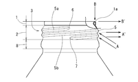
- a thread inspection apparatus (hereinafter referred to as “inspection apparatus”) 20 according to an embodiment has an opening end facing outward in order to fit a cap with a liner (not shown).
- the curled part 1 and the threaded part 2 with respect to the bottle can 4 having the overall cylindrical base part 3 comprising the curled part 1 curled and the threaded part 2 to which the cap is screwed under the curled part 1.
- the base portion 3 indicates a portion including a curl portion 1, a screw portion 2, and a jaw portion 8 for locking the lower end of the cap below the screw portion 2. Further, in the threaded portion 2, a strip that protrudes outward in the radial direction is referred to as a thread strip 5.
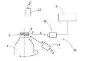
- the screw portion inspection apparatus 20 holds the bottle can 4 by vacuum suction or the like and rotates the rotating means 21 around the can axis X, and the illumination light A so as to cover the screw portion 2 of the bottle can 4 in the imaging area ⁇ .
- Imaging means 24 for continuously acquiring inspection images including the respective reflected lights A ′ and B ′ by the illumination lights A and B from the light source, and the screw start of the screw portion 2 based on the inspection images obtained by the imaging means 24
- Thread portion inspection means 25 for detecting the portion 6 and inspecting the shape of the screw portion 2 with the screw start portion 6 as a reference.
- the imaging area ⁇ is set to a range that covers the entire base portion 3 from the top end of the top surface 1 a of the curled portion 1 to the lower ends of the screw portion 2 and the jaw portion 8 as described later.
- the screw portion illuminating means 22 irradiates the illumination light A to a range covering the imaging area ⁇ in the screw portion 2, while the curl illuminating means 23 covers the imaging area ⁇ on the top surface 1 a of the curled portion 1.
- the illumination light B is irradiated to the range to be performed (FIG. 2).
- the screw portion illuminating means 22 is arranged radially outward with respect to the screw portion 2 and below the can axis X so as to irradiate the inclined surface 5b arranged below the ridge line 5a of the screw 5.
- the inclined surface 5b below the ridge line 5a of the screw 5 is irradiated obliquely from below.
- the optical axis of the illumination light A emitted from the screw portion illumination means 22 is arranged so as to have an inclination angle ⁇ of 15 ° to 80 ° with respect to the can axis X.
- the curl illumination means 23 is arranged above the curl part 1 of the bottle can 4 in the can axis X direction, and irradiates the top surface 1a of the curl part 1 downward along the can axis X direction.
- the imaging means 24 continuously images a line-shaped imaging area ⁇ by a line sensor camera, from the top end of the top surface 1a of the curled portion 1 of the bottle can 4 to the lower ends of the screw portion 2 and the jaw portion 8.
- the imaging area ⁇ is set on the line strip along the can axis X direction so as to include the entire base portion 3 of the first lens portion.
- the inspection image is captured as a black and white image composed of a high luminance part due to the reflected light of the illumination light from both illumination means 22 and 23 and a low luminance part around it.
- Inspection images including A ′ and B ′ are continuously captured.
- the inspection image is input to the screw portion inspection means 25 connected to the imaging means 24 and used for inspection of the screw portion shape.
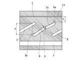
- the inspection image acquired by the imaging unit 24 includes the screw 5 that is reflected by the reflected light A ′ of the illumination light A from the screw portion illumination unit 22.
- An image D of the inclined surface 5b and an image E of the top surface 1a of the curled portion 1 by the reflected light B ′ of the illumination light B from the curled portion illuminating means 23 are simultaneously acquired.
- the vertical direction is the can axis X direction.
- the reference position of the inspection image is specified from the imaging results of both reflected lights A ′ and B ′, and the screw start portion 6 is specified from the reference position.
- the upper edge Ea catches the topmost end of the top surface 1a, and the upper edge Ea is set as the reference position. Then, the end portion Da of the image D of the screw 5 existing in a region separated by a predetermined distance L along the can axis X direction from the reference position is detected, and when this end portion Da is detected, the end portion Da is screwed. The position of the start part 6 is assumed.
- the end of the thread 5 can be identified on the inspection image by the shape of the boundary between the high-luminance portion and the low-luminance portion due to reflected light (for example, L-shaped hook).
- the end portion Db of the image D of the screw 5 in the region of the predetermined length position with the predetermined lead angle with respect to the end portion Da corresponding to the screw start portion is set as the position of the screw end portion 7.
- the screw start portion 6 and the screw end portion 7 are specified because the image D of the screw 5 is obtained by the reflected light from the inclined surface 5b below the ridge line 5a.
- the ridge line 5a of the strip 5 is captured. Therefore, by detecting the positions of both end portions Da and Db of the upper edge Dc of the image D, the positions of the screw start portion 6 and the screw end portion 7 on the ridge line 5a of the screw 5 can be specified.
- the displacement of the upper edge Dc of the thread 5 in the image D is tracked with respect to the straight line Q connecting the positions of both ends Da and Db corresponding to the screw start portion 6 and the screw end portion 7.
- a bend is detected (in FIG. 4, the image D in the center portion shows the bend with emphasis, and the largest displacement is indicated by a symbol G).
- the separation distance H in the can axis direction in the image D of adjacent screw strips (a plurality of screw strips are captured by the rotation of the bottle can), for example, the image D of the screw strip captured above from one end Db.
- the screw pitch is calculated from the spacing H along the can axis direction up to the upper edge Dc.
- the screw portion inspection apparatus 20 specifies the reference position of the inspection image by the reflected light B ′ of the illumination light B from the curl illumination unit 23 that irradiates the top surface 1a of the curl portion 1, and the reference position. Since the position (screw pitch, screw bending, etc.) of the screw part 2 is inspected after the position of the screw start part 6 of the screw part 2 is specified from the screw part 2, the screw part can be identified by accurately specifying the position of the screw start part 6. The shape of 2 can be accurately inspected.
- the curled portion 1 can be scanned over the entire circumference by the reflected light B ′ of the illumination light B from the curled portion illumination means 23.
- the image E of the top surface 1a of the curled portion 1 can be grasped linearly as shown in FIG. 4, but if the top surface 1a of the curled portion 1 has a dent, the image E of the top surface 1a is It is displaced to. Therefore, when the image E of the top surface 1a is tracked and the displacement exceeds a predetermined value, it can be determined that the curl portion 1 is abnormal.
- the symbol F is an image that captures the jaw 8.
- the screw portion illumination means 22 and the curl portion illumination means 23 irradiate the screw portion 2 and the top surface 1a of the curl portion 1 at the same time, and these reflected lights A ′ and B ′.
- the reflected light A ′ and B ′ may be alternately and continuously imaged while alternately flickering the screw portion illumination means 22 and the curl portion illumination means 23. Good.
- both the illumination means 22 and 23 are alternately blinked at a frequency of 60 Hz, for example, and the reflected light A ′, B ′ is continuously and alternately imaged by the imaging means 24 by the line sensor camera, so that the reflected light A ′ by the illumination light A from the screw portion illumination means 22 and the reflected light by the illumination light B from the curl illumination means 23 An image in which B ′ is alternately arranged is obtained.
- B ′ can be extracted separately.
- FIG. 6A is an inspection image mainly capturing the reflected light A ′ from the illumination light A from the screw portion illumination means 22, and FIG. 6B is the reflected light B from the illumination light B from the curl illumination means 23.
- This is an inspection image mainly capturing ′.
- These inspection images show the same coordinate position.
- FIG. 4 an inspection image obtained by combining (a) and FIG. 6B is obtained, and the illumination light B from the curl illumination means 23 interferes with the illumination light A from the screw illumination means 22 irradiated to the screw portion 2.
- the screw start portion 6 is detected from the inspection image from the imaging means 24 by the computer processing of the screw portion inspection means 31 as follows. After separation into two inspection images shown in FIGS. 6A and 6B, in the inspection image shown in FIG. 6B, imaging of reflected light B ′ by illumination light B from the curl illumination means 23 is performed. From the result, the image E of the curled portion 1 is recognized, the coordinate of the top end of the top surface 1a is detected, and the coordinate position in the inspection image of FIG. 6A corresponding to the coordinate position of the top end is determined.
- ⁇ Provide a bottle can thread inspection device that can accurately and quickly inspect the bottle can thread.
Landscapes
- Physics & Mathematics (AREA)
- General Physics & Mathematics (AREA)
- Biochemistry (AREA)
- General Health & Medical Sciences (AREA)
- Health & Medical Sciences (AREA)
- Life Sciences & Earth Sciences (AREA)
- Chemical & Material Sciences (AREA)
- Analytical Chemistry (AREA)
- Pathology (AREA)
- Immunology (AREA)
- Engineering & Computer Science (AREA)
- Computer Vision & Pattern Recognition (AREA)
- Quality & Reliability (AREA)
- Theoretical Computer Science (AREA)
- Investigating Materials By The Use Of Optical Means Adapted For Particular Applications (AREA)
- Length Measuring Devices By Optical Means (AREA)
- Image Processing (AREA)
- Image Analysis (AREA)
Abstract
Priority Applications (5)
| Application Number | Priority Date | Filing Date | Title |
|---|---|---|---|
| EP12797187.7A EP2719996B1 (fr) | 2011-06-06 | 2012-06-04 | Appareil d'inspection d'une canette à bouteille filetée |
| CN201280028005.4A CN103597315B (zh) | 2011-06-06 | 2012-06-04 | 瓶罐的螺纹部检查装置 |
| US14/124,001 US9335278B2 (en) | 2011-06-06 | 2012-06-04 | Inspection equipment for screw part of bottle-can |
| BR112013031252A BR112013031252A2 (pt) | 2011-06-06 | 2012-06-04 | equipamento de inspeção para a parte roscada de uma lata do tipo garrafa |
| KR1020137033024A KR101986389B1 (ko) | 2011-06-06 | 2012-06-04 | 보틀캔의 나사부 검사 장치 |
Applications Claiming Priority (2)
| Application Number | Priority Date | Filing Date | Title |
|---|---|---|---|
| JP2011-126218 | 2011-06-06 | ||
| JP2011126218A JP5698608B2 (ja) | 2011-06-06 | 2011-06-06 | ボトル缶のねじ部検査装置 |
Publications (1)
| Publication Number | Publication Date |
|---|---|
| WO2012169472A1 true WO2012169472A1 (fr) | 2012-12-13 |
Family
ID=47296035
Family Applications (1)
| Application Number | Title | Priority Date | Filing Date |
|---|---|---|---|
| PCT/JP2012/064411 WO2012169472A1 (fr) | 2011-06-06 | 2012-06-04 | Appareil d'inspection du filetage d'une bouteille |
Country Status (7)
| Country | Link |
|---|---|
| US (1) | US9335278B2 (fr) |
| EP (1) | EP2719996B1 (fr) |
| JP (1) | JP5698608B2 (fr) |
| KR (1) | KR101986389B1 (fr) |
| CN (1) | CN103597315B (fr) |
| BR (1) | BR112013031252A2 (fr) |
| WO (1) | WO2012169472A1 (fr) |
Cited By (1)
| Publication number | Priority date | Publication date | Assignee | Title |
|---|---|---|---|---|
| ITTO20130644A1 (it) * | 2013-07-30 | 2015-01-31 | Arol Spa | Macchina per l'applicazione di capsule filettate a contenitori |
Families Citing this family (11)
| Publication number | Priority date | Publication date | Assignee | Title |
|---|---|---|---|---|
| WO2014129580A1 (fr) * | 2013-02-21 | 2014-08-28 | ユニバーサル製缶株式会社 | Procédé d'inspection, dispositif d'inspection et unité d'inspection pour corps de boîte |
| CN104568980A (zh) * | 2014-12-30 | 2015-04-29 | 苏州巨能图像检测技术有限公司 | Aoi检测装置 |
| AU2016270992A1 (en) * | 2015-06-03 | 2017-12-21 | Christian Beck | System and method for inspecting containers using multiple radiation sources |
| IT201600082297A1 (it) * | 2016-08-04 | 2018-02-04 | Antares Vision S R L | Dispositivo per il controllo di qualità in continuo di contenitori |
| JP2018044890A (ja) * | 2016-09-15 | 2018-03-22 | アサヒビール株式会社 | 容器装着フィルムの検出装置、フィルム装着容器の検出システム、および容器装着フィルムの検出方法 |
| CN114813787A (zh) * | 2017-02-06 | 2022-07-29 | 东洋玻璃株式会社 | 玻璃瓶的检查装置 |
| CN108154506B (zh) * | 2017-12-27 | 2020-07-03 | 合肥市雅视智能科技有限公司 | 一种六角螺母自动检测方法 |
| US11313675B2 (en) * | 2018-05-02 | 2022-04-26 | Nippon Steel Corporation | Thread shape measuring apparatus and measuring method |
| KR102049038B1 (ko) * | 2018-06-21 | 2019-11-26 | 대우공업 (주) | 파이프 너트용 나사산 검사방법 |
| CN113432531A (zh) * | 2021-06-22 | 2021-09-24 | 广东工业大学 | 一种瓶胚尺寸测量方法 |
| EP4242642A1 (fr) * | 2022-03-09 | 2023-09-13 | Analitica d.o.o. | Appareil d'examen de contenants |
Citations (7)
| Publication number | Priority date | Publication date | Assignee | Title |
|---|---|---|---|---|
| JPH07209210A (ja) * | 1993-12-06 | 1995-08-11 | Elpatronic Ag | 容器の透明領域を光学的に検査する方法と装置 |
| JP2000503401A (ja) * | 1996-10-30 | 2000-03-21 | クロネス・アクチェンゲゼルシャフト | びん等の検査装置 |
| JP2003194532A (ja) * | 2001-12-27 | 2003-07-09 | Daiwa Can Co Ltd | 容器のネジ部検査装置および検査方法 |
| JP2003254720A (ja) | 2002-02-27 | 2003-09-10 | Mitsubishi Materials Corp | ボトル缶の測定方法 |
| JP2003262511A (ja) | 2002-03-08 | 2003-09-19 | Mitsubishi Materials Corp | ボトル缶の測定検査方法 |
| JP2003262507A (ja) | 2002-03-07 | 2003-09-19 | Mitsubishi Materials Corp | ボトル缶の測定装置及び測定方法 |
| JP2006300711A (ja) * | 2005-04-20 | 2006-11-02 | Omron Corp | 金属製キャップの不良検査方法、この検査のための調整方法、および金属製キャップの不良検査装置 |
Family Cites Families (6)
| Publication number | Priority date | Publication date | Assignee | Title |
|---|---|---|---|---|
| JPS6176941A (ja) * | 1984-09-21 | 1986-04-19 | Nippon Denso Co Ltd | ネジの外観不良の検査方法及びその装置 |
| US5610391A (en) * | 1994-08-25 | 1997-03-11 | Owens-Brockway Glass Container Inc. | Optical inspection of container finish dimensional parameters |
| JPH1062359A (ja) * | 1996-08-26 | 1998-03-06 | Oji Koei Kk | 欠陥検査方法およびその装置 |
| DE19920007C1 (de) * | 1999-05-03 | 2000-07-27 | Krones Ag | Vorrichtung zur Inspektion von Dichtflächen an Flaschen |
| US6104482A (en) * | 1999-12-02 | 2000-08-15 | Owens-Brockway Glass Container Inc. | Container finish check detection |
| EP1560017B1 (fr) * | 2002-10-18 | 2009-08-05 | Kirin Techno-System Company, Limited | Dispositif d'inspection de bouteilles en verre |
-
2011
- 2011-06-06 JP JP2011126218A patent/JP5698608B2/ja active Active
-
2012
- 2012-06-04 KR KR1020137033024A patent/KR101986389B1/ko active IP Right Grant
- 2012-06-04 EP EP12797187.7A patent/EP2719996B1/fr active Active
- 2012-06-04 BR BR112013031252A patent/BR112013031252A2/pt not_active Application Discontinuation
- 2012-06-04 US US14/124,001 patent/US9335278B2/en active Active
- 2012-06-04 WO PCT/JP2012/064411 patent/WO2012169472A1/fr active Application Filing
- 2012-06-04 CN CN201280028005.4A patent/CN103597315B/zh active Active
Patent Citations (7)
| Publication number | Priority date | Publication date | Assignee | Title |
|---|---|---|---|---|
| JPH07209210A (ja) * | 1993-12-06 | 1995-08-11 | Elpatronic Ag | 容器の透明領域を光学的に検査する方法と装置 |
| JP2000503401A (ja) * | 1996-10-30 | 2000-03-21 | クロネス・アクチェンゲゼルシャフト | びん等の検査装置 |
| JP2003194532A (ja) * | 2001-12-27 | 2003-07-09 | Daiwa Can Co Ltd | 容器のネジ部検査装置および検査方法 |
| JP2003254720A (ja) | 2002-02-27 | 2003-09-10 | Mitsubishi Materials Corp | ボトル缶の測定方法 |
| JP2003262507A (ja) | 2002-03-07 | 2003-09-19 | Mitsubishi Materials Corp | ボトル缶の測定装置及び測定方法 |
| JP2003262511A (ja) | 2002-03-08 | 2003-09-19 | Mitsubishi Materials Corp | ボトル缶の測定検査方法 |
| JP2006300711A (ja) * | 2005-04-20 | 2006-11-02 | Omron Corp | 金属製キャップの不良検査方法、この検査のための調整方法、および金属製キャップの不良検査装置 |
Non-Patent Citations (1)
| Title |
|---|
| See also references of EP2719996A4 * |
Cited By (3)
| Publication number | Priority date | Publication date | Assignee | Title |
|---|---|---|---|---|
| ITTO20130644A1 (it) * | 2013-07-30 | 2015-01-31 | Arol Spa | Macchina per l'applicazione di capsule filettate a contenitori |
| EP2832680A1 (fr) * | 2013-07-30 | 2015-02-04 | Arol S.p.A. | Machine pour appliquer des bouchons filetés sur des récipients |
| US9623990B2 (en) | 2013-07-30 | 2017-04-18 | Arol S.P.A. | Machine for applying threaded caps to containers |
Also Published As
| Publication number | Publication date |
|---|---|
| US9335278B2 (en) | 2016-05-10 |
| CN103597315B (zh) | 2016-08-17 |
| BR112013031252A2 (pt) | 2016-12-06 |
| EP2719996B1 (fr) | 2020-05-06 |
| EP2719996A1 (fr) | 2014-04-16 |
| US20140125793A1 (en) | 2014-05-08 |
| JP2012251931A (ja) | 2012-12-20 |
| CN103597315A (zh) | 2014-02-19 |
| EP2719996A4 (fr) | 2014-11-05 |
| JP5698608B2 (ja) | 2015-04-08 |
| KR101986389B1 (ko) | 2019-06-05 |
| KR20140053019A (ko) | 2014-05-07 |
Similar Documents
| Publication | Publication Date | Title |
|---|---|---|
| JP5698608B2 (ja) | ボトル缶のねじ部検査装置 | |
| KR101900123B1 (ko) | 보틀캔의 구금부 검사 장치 | |
| JP5324415B2 (ja) | 缶の凹凸検出装置 | |
| JPH09169392A (ja) | 画像式打栓状態検査装置 | |
| JP2015040796A (ja) | 欠陥検出装置 | |
| KR101936974B1 (ko) | 보틀캔의 구금부 검사 방법 및 검사 장치 | |
| JP7469935B2 (ja) | ボトル缶のねじ部検査方法及びボトル缶のねじ部検査装置 | |
| JP5959430B2 (ja) | ボトルキャップの外観検査装置及び外観検査方法 | |
| JP6983604B2 (ja) | 容器口部検査装置及び容器口部検査方法 | |
| JP4217399B2 (ja) | ボトル・キャップ組立体の検査装置 | |
| JP6393663B2 (ja) | 表面検査装置 | |
| JP2006145377A (ja) | 塗装面欠陥の検出方法および装置 | |
| JP5827028B2 (ja) | ボトル缶の口金部検査装置 | |
| JP5451560B2 (ja) | 樹脂製キャップ内部品の検査装置および樹脂製キャップ内部品の検査方法 | |
| JP2023158295A (ja) | チューブ容器検査装置 | |
| JP2004250042A (ja) | キャップ巻締位置の検出特性に優れたキャップ | |
| JP5991463B2 (ja) | 検査装置 | |
| JP2007024769A (ja) | ボトル缶の測定方法 |
Legal Events
| Date | Code | Title | Description |
|---|---|---|---|
| 121 | Ep: the epo has been informed by wipo that ep was designated in this application |
Ref document number: 12797187 Country of ref document: EP Kind code of ref document: A1 |
|
| WWE | Wipo information: entry into national phase |
Ref document number: 2012797187 Country of ref document: EP |
|
| WWE | Wipo information: entry into national phase |
Ref document number: 14124001 Country of ref document: US |
|
| NENP | Non-entry into the national phase |
Ref country code: DE |
|
| ENP | Entry into the national phase |
Ref document number: 20137033024 Country of ref document: KR Kind code of ref document: A |
|
| REG | Reference to national code |
Ref country code: BR Ref legal event code: B01A Ref document number: 112013031252 Country of ref document: BR |
|
| ENP | Entry into the national phase |
Ref document number: 112013031252 Country of ref document: BR Kind code of ref document: A2 Effective date: 20131205 |